


Ceiling Heat
Panels
FILE #E21069
Installation & Maintenance Instructions
Dear Owner, a
Congratulations! Thank you for purchasing this new heater manufactured by Marley Engineered Products. You have made a wise investment selecting the highest quality product in the heating industry. Please carefully read the installation and maintenance directions shown in this manual. You should enjoy years of efficient heating comfort with this product from Marley Engineered Products . . . the industry’s leader in design, manufacturing, quality, and service.
. . . The Employees of
Marley Engineered Products
! WARNINGa
Read Carefully - These instructions are written to help you prevent difficulties that might arise during installation of heaters. Studying the instructions first may save you considerable time and money later. Observe the following procedures and cut your installation time to a minimum.
1.To prevent possible electrical shock, disconnect ALL power coming to heater at main service panel before wiring or servicing.
2.All wiring must be in accordance with the National and Local Electrical Codes and the heater must be grounded as a precaution against possible electrical shock.
3.Verify the power supply voltage coming to the heater matches the ratings printed on the heater nameplate before energizing.
4.This heater is NOT suitable for use in hazardous locations as described by the National Fire Protection Association (NFPA). DO NOT use in areas where gasoline, paint or other flammable liquids are used or stored. DO NOT use in wet areas or areas where corrosive agents are present, such as marine, green house, chemical storage, swimming pool, or areas of high humidity, unless special custom panels are used. Special custom panels may be available for certain environments. Contact manufacturer for details.
5.To prevent a possible injury or fire from falling panels, panels MUST be securely fastened to the building structure.
When T-bar Mounted: The T-bar grid work frame must be secured to the building to provide adequate support for the panels. Holes are provided in the sides of each panel for attachment of steel support wires for additional support of the panels where the T-bar grid work frame strength is questionable. Support wire must be steel and at least 18 gage (0.047 in. dia. / 0.119 cm. dia). When Surface or Recess Mounted: The surface or recess mounting frame accessory kits (Models ASF . . . or ARF . . . ) must be used. Kits must be sized to match heaters being used. Do not drill holes, drive nails, screws, etc., into or through panels. To do so may result in fire, electric shock, or permanent damage to heater. Surface or recess kits must be securely fastened to building structure using a minimum of four (4) 1/4 inch (.635 cm) diameter screws or bolts.
6. To prevent possible fire due to the overheating of wiring, all field wiring coming to heating panels must be rated at least 90° C when junction box is allowed to lie on top of heating panel or is enclosed between heater and ceiling above. When thermal insulation is used on top of heater, the junction box must be above the insulation.
7. Panels are intended for ceiling installation only. Do not install on walls, floor, etc. Painted (bottom) surface of panel is hot. Panels must be installed at least seven (7) feet off floor and should not be installed where panels can be easily contacted during use. Keep combustibles at least 3 feet (0.9m) from face of heater.
|
|
GENERAL |
|
Marley Engineered Products Radiant Heating Panels are |
Although the heater contains thermal insulation, it will |
designed to provide comfort by warming the surfaces |
operate more efficiently in well insulated rooms. Four or |
below the heaters just as the sun warms surfaces through |
more inches of insulation above an exposed ceiling will |
radiant energy. This heating process heats objects in a |
increase both comfort and economy. |
room without having to bring the room air temperature up |
|
to the same level. These panels are ideal for spot heating |
The heaters are intended to be controlled by a remote wall |
in high heat loss areas. Panels may be installed side by |
mounted thermostat. The thermostat should be located in |
side or individually above areas requiring additional heat. If |
the same room on a side wall. It should also be above |
used as a sole source of heat, more heat will be felt while |
five feet above the floor, but not directly under the heater. |
standing directly under the panel. |
|
SAVE THESE INSTRUCTIONS
NOTE: For a period of time after the panels are put into |
|||||||
operation the owner may notice a “new smell” coming |
|||||||
from the heaters. This is expected on new installations |
|||||||
and will dissipate after approximately 24 hours of opera- |
|||||||
tion. |
|
PAINTING |
|
|
|
||
|
|
|
|
|
|
|
|
1. Heaters may be repainted. Do not remove paint from |
|||||||
|
heaters. The surface must be first free of grease or |
||||||
|
oil. Use only a thin brush-on coat of high quality pure |
||||||
|
acrylic water base flat latex. An off-white will give better |
||||||
|
coverage. |
|
|
|
|
|
|
|
Do not paint with aluminum, oil base, vinyl-latex or |
||||||
|
rubber-base latex paint. |
|
|
|
|||
|
|
|
|
T-BAR MOUNTING |
|
|
|
1. The heater panels are designed for installation in T-Bar |
|||||||
|
ceilings. |
|
|
|
|
|
|
|
|
|
|
|
|
|
|
|
|
|
|
CAUTION |
! |
|
|
|
|
|
|
|
|
|
|
|
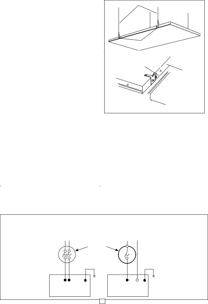
To prevent possible injury from falling panels, the T-Bar |
|
|||||
|
must be securely fastened to the building structure and |
|
|
||||
|
capable of supporting the weight of the panel (30 |
|
|
||||
|
pounds). Extra holes are provided for suspending the |
|
|
||||
|
heater panel (see Fig. 1) on steel wires no smaller than |
|
|
||||
|
No. 18 ga. (0.047 in. diameter / 0.119 cm diameter). |
|
|
||||
|
These extra support wires must be used where T-Bar |
|
|
||||
|
strength is inadequate or where vibration is anticipated. |
|
|
||||
|
|
|
|
|
|
|
|
|
|
|
|
|
|
|
|
2. Three (3) inch (7.67cm) minimum distance must be pro- |
|||||||
|
vided between the front painted surface and the ceiling |
||||||
|
above. However, installation may be difficult and six (6) |
||||||
|
inches (15.2 cm) or more clearance will improve instal- |
||||||
|
lation of heaters and inspection or wiring. It may be nec- |
||||||
|
essary to remove a cross tee for installation when T-Bars |
||||||
|
are at close distances to the ceiling. |
|
|
|
|||
3. Locate T-Bar hanger wires at the corners where the |
|||||||
|
cross tees intersect the main tees so that they do not |
||||||
|
interfere with installation or removal of panels. |
||||||
4. The heater panels are supplied with four built in hang- |
|||||||
|
ing/hold-down clips which are located on each long side of |
||||||
|
the heater panel. The clips can be used either to hang the |
||||||
|
heater with support wires (see Figure 1) or bent as hold |
||||||
|
down clips to the T-Bar frame (see Figure 2). Carefully lift |
||||||
|
heater panel into place, making sure hold down clips hook |
||||||
|
securely over T-bar (see Figure 2). |
|
|
|
|||
|
|
|
|
|
|
|
|
|
|
|
|
CAUTION |
|
|
|
|
|
|
|
|
|
|
|
|
To prevent possible injury from electric shock, make |
||||||
|
sure that electricity is turned off at the main switch. All |
|
|||||
|
wiring must be done in accordance with national and |
|
|||||
|
local codes and the unit must be properly grounded as |
|
|||||
|
a precaution against electrical shock. |
|
|
|
|||
|
|
|
|
|
|
|
|
|
|
|
|
|
|
|
|
|
|
|
|
|
|
|
|
|
Fig. 3 |
|
|
|
|
|
|
|
|
|
|
|
|
|
|
Fig. 1 |
SUPPORT WIRES |
|
HOLD DOWN CLIPS |
Fig. 2 |
|
HOLD DOWN CLIP |
HEATER |
|
|
|
PANEL |
T-BAR 


WIRING
1. Maximum number of heaters per circuit is limited to circuit wiring and thermostat or switch capacity. See catalog for available thermostats and Warning No. 2.
2. Make wiring connections in accordance with Fig. 3 (on following page) and wiring instructions. The heater must be properly grounded as a precaution against electrical shock. Use a properly grounded junction box for connecting the heater to the power supply.
3. Always use a properly grounded junction box when splicing. See wiring diagrams for proper connections. Install only in a location where the power supply con- nections will be accessible. Install junction box as far above panel as possible and above building insulation, where present. Use field wiring suitable for 90 ºC if junction box is allowed to lie on heater or is enclosed between heater and ceiling above. When installed in a drop ceiling, the wiring terminals should be accessible through removable ceiling sections with adequate clearance to permit access to the top of the heater.
SEE NAMEPLATE FOR |
SEE NAMEPLATE FOR |
LINE VOLTAGE SUPPLY |
LINE VOLTAGE SUPPLY |
BLACK BLACK |
G |
208 OR 240 VOLT
HEATER
BLACK WHITE G
120, 277 OR 347 VOLT
HEATER

SURFACE MOUNTING |
|
|
|
|||
1. The Surface Mounting Kit comes a in separate carton which |
||||||
contain two side frames, two end frames, and eight assem- |
||||||
bly screws. |
|
|
|
|
|
|
2. Assemble the end frames to the side frames using the |
||||||
screws provided (see Fig. 4) before installing on the ceiling. |
||||||
|
|
|
|
|
|
|
|
CAUTION |
! |
|
|
||
|
|
|
|
|
|
|
To prevent possible injury from falling panels, use at |
|
|||||
least four screws (1/4" or 0.635 minimum diameter) to |
|
|
||||
secure each side frame. Screws must thread securely |
|
|
||||
into a sturdy structural member of the ceiling, such as a |
|
|
||||
ceiling joist. It may be necessary to frame-in an extra |
|
|
||||
support member. Do not finish from dry-wall, plater or |
|
|
||||
other finish ceiling materials. |
|
|
|
|
|
|
|
|
|
|
|
|
|
|
|
|
|
|
|
|
|
|
|
|
|
|
|
|
|
|
|
|
|
|
|
|
|
SCREWS |
|
|
|
|
END FRAME |
|
|
|
||
|
|
|
|
|
|
|
|
|
|
|
|
|
|
SIDE FRAME
MOUNTING
HOLES
Fig. 4
3
smaller than 2"x 4" (5cm x 10cm) for support. Use screws no smaller than number 10 in each hole provided in side and end frames.
Fig. 6 SIDE FRAME
END FRAME
CORNER
3.Insert the heater panel through the opening (see Fig. 7) and make wiring connections (see Fig. 3 and WIRING instructions). The heater must be properly grounded as a precaution against electrical shock. Use a properly grounded junction box for connecting the heater to the power supply.
Be sure electricity is turned off at main switch before wiring to prevent possible injury from electric shock.
A Fig. 7
|
|
|
|
|
|
|
|
Panel width plus |
|
|
|
|
3/8” (9.5 mm) |
|
|
|
|
|
|
Panel |
|
|
|
|
length |
|
|
|
|
plus 3/8” |
|
|
|
|
|
(ALL DIMENSIONS |
|
||
(9.5 mm) |
|
|
||
|
ARE INSIDE) |
|
||
|
|
|
||
|
|
|
|
|
4.Loosely screw side and end frames to ceiling opening, then attach corners in place (see Fig. 8).
5.After attaching corners, tighten screws securely.
6.Carefully lower heater panel in place on frames.
Fig. 8
PLACE CORNER
IN POSITION AND
SECURE BY
BENDING TABS UP
|
|
|
|
|
|
|
|
|
|
|
|
|
|
|
|
|
|
|
|
|
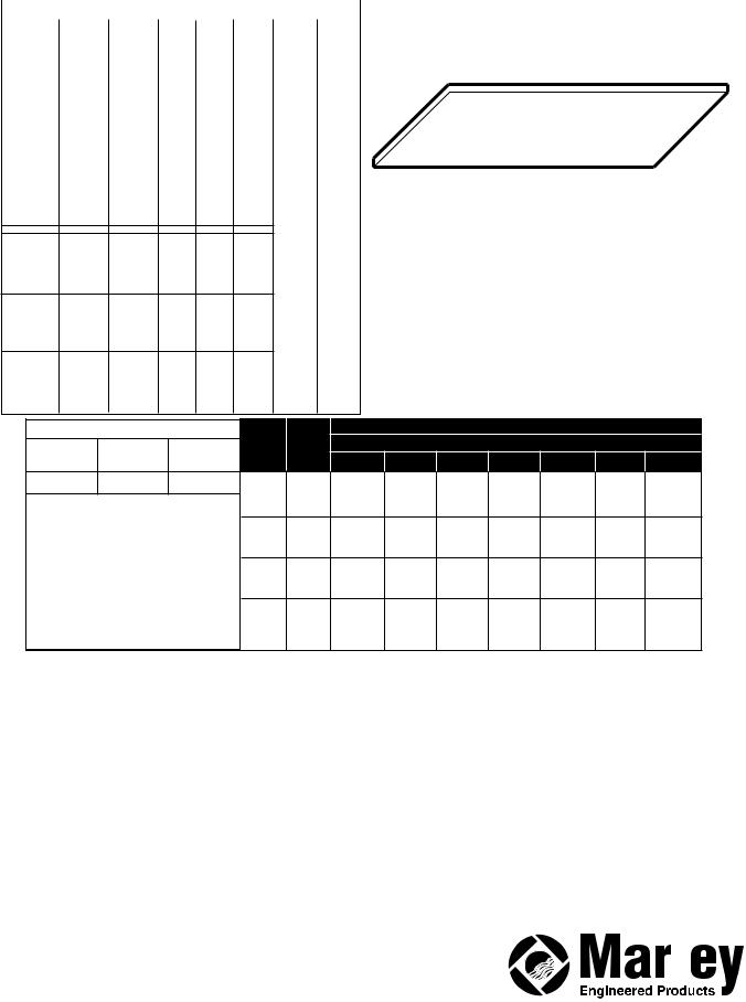
ELECTRIC RADIANT HEATING PANELS |
|
|
|
|
SPECIFICATIONS: STANDARD SIZE |
|
|
|
|
|
|
|
|
|
|
|
||||||||
|
|
|
|
|
|
|
|
|
|
|
|
|
|
|
|
|
|
|
|
|
|
|
|
|
|
|
|
|
|
|
|
|
|
|
|
|
|
|
|
|
|
|
|
|
|
|
Model |
|
Catalog |
|
Catalog |
|
Volts |
|
Watts |
|
BUT/ |
|
|
|
DIM |
|
DIM |
|
|
|
|
|
|
|
|
|
|
|
|
|
|
|
|
|
|
|
|||||||||
|
Number |
|
Number |
|
Number |
|
|
|
HR |
|
|
|
(IN.) |
|
(CM.) |
|
|
|
|
|||
|
|
|
|
|
|
|
|
|
|
|
|
|
|
|
|
|
|
|
|
|
|
|
|
ATL24241A |
|
CP2501 |
|
CP251 |
120 |
250 |
853 |
|
|
|
|
|
|
|
|
|
|
|
|||
|
ATL24242A |
|
CP2502 |
|
CP252 |
240 |
250 |
853 |
|
|
|
|
|
|
|
|
|
|
|
|||
|
ATL24248A |
|
CP2508 |
|
CP258 |
208 |
250 |
853 |
|
|
|
|
|
|
|
|
|
|
|
|||
|
ATL24247A |
|
CP2507 |
|
CP257 |
277 |
250 |
853 |
|
|
|
|
|
|
|
|
|
|
|
|||
|
|
|
|
|
|
|
|
|
|
|
|
|
|
|||||||||
|
ATL24243A |
|
CP2503 |
|
CP253 |
347 |
250 |
853 |
24 |
61 |
|
|
|
|
|
|||||||
|
ATM24241A |
|
CP3101 |
|
CP311 |
120 |
310 |
1058 |
|
|
|
X |
|
X |
|
|
|
|||||
|
ATM24242A |
|
CP3102 |
|
CP312 |
240 |
310 |
1058 |
|
|
|
|
|
|
|
|||||||
|
|
|
|
|
|
|
|
|
|
|
|
|
|
|||||||||
|
ATM24248A |
|
CP3108 |
|
CP318 |
208 |
310 |
1058 |
24 |
122 |
|
|
|
|
|
|||||||
|
ATM24247A |
|
CP3107 |
|
CP317 |
277 |
310 |
1058 |
|
|
|
X |
|
X |
|
|
|
|||||
|
ATM24243A |
|
CP2103 |
|
CP313 |
347 |
310 |
1058 |
|
|
|
|
|
|
|
|||||||
|
|
|
|
|
|
|
|
|
|
|
|
|
|
|||||||||
|
ATH24241A |
|
CP3751 |
|
CP371 |
120 |
375 |
1280 |
1 |
2.5 |
|
|
|
|
|
|||||||
|
ATH24242A |
|
CP3752 |
|
CP372 |
240 |
375 |
1280 |
|
|
|
|
|
|
|
|
|
|
|
|||
|
ATM24248A |
|
CP3758 |
|
CP378 |
208 |
375 |
1280 |
|
|
|
|
|
|
|
|
|
|
|
|||
|
ATM24247A |
|
CP3757 |
|
CP377 |
277 |
375 |
1280 |
|
|
|
|
|
|
|
|
|
|
|
|||
|
ATM24243A |
|
CP3753 |
|
CP373 |
347 |
375 |
1280 |
|
|
|
|
|
|
|
|
|
|
|
|||
ATL24481A |
CP5001 |
CP501 |
120 |
500 |
1706 |
|
|
|
|
|
|
|
|
|
ATL24482A |
CP5002 |
CP502 |
240 |
500 |
1706 |
|
|
|
|
|
|
|
|
|
ATL24488A |
CP5008 |
CP508 |
208 |
500 |
1706 |
|
|
|
|
|
|
|
|
|
ATL24487A |
CP5007 |
CP507 |
277 |
500 |
1706 |
24 |
61 |
|
|
|
|
|
|
|
ATL24483A |
CP5003 |
CP503 |
347 |
500 |
1706 |
|
|
|
|
|
|
|||
X |
X |
|
|
|
|
|
|
|||||||
ATM24481A |
CP6251 |
CP621 |
120 |
625 |
2133 |
|
|
|
|
|
|
|||
ATM24482A |
CP6252 |
CP622 |
240 |
625 |
2133 |
48 |
122 |
|
|
|
|
|
|
|
ATM24488A |
CP6258 |
CP628 |
208 |
625 |
2133 |
|
|
|
|
|
|
|||
X |
X |
|
|
|
|
|
|
|||||||
ATM24487A |
CP6267 |
CP627 |
277 |
625 |
2133 |
|
|
|
|
|
|
|||
ATM24483A |
CP6253 |
CP623 |
347 |
625 |
2133 |
1 |
2.5 |
|
|
|
|
|
|
|
ATH24481A |
CP7501 |
CP751 |
120 |
750 |
2560 |
|
|
|
|
|
|
|||
|
|
|
|
|
|
|
|
|||||||
ATH24482A |
CP7502 |
CP752 |
240 |
750 |
2560 |
|
|
|
|
|
|
|
|
|
ATH24488A |
CP7508 |
CP758 |
208 |
750 |
2560 |
|
|
|
|
|
|
|
|
|
ATH24487A |
CP7507 |
CP757 |
277 |
750 |
2560 |
|
|
|
|
|
|
|
|
|
ATH24483A |
CP7503 |
CP753 |
347 |
750 |
2560 |
|
|
|
|
|
|
|
|
|
SPECIFICATIONS: CUSTOM SIZE |
a |
|
|
|
|
|
|
|
|
|||||
Model |
Catalog |
|
Catalog |
|
|
|
|
|
|
|
|
|
||
Number |
Number |
Number |
|
Density |
|
|
|
|
|
|
|
|||
|
|
|
|
|
|
|
|
|
|
|
|
|
||
AT+**@@#A |
BT+**@@# |
QT+**@@# |
|
High |
155 |
235 |
315 |
390^ |
N/A |
N/A |
N/A |
|||
|
|
|
|
|
|
|||||||||
+ = Watt Density |
|
|
10”-13” |
Med. |
130 |
195 |
260 |
325^ |
N/A |
N/A |
N/A |
|||
|
|
|
Low |
105 |
155 |
210 |
260^ |
N/A |
N/A |
N/A |
||||
(H=High; M=Medium; L=Low) |
|
|||||||||||||
|
High |
235 |
350 |
470 |
585^ |
N/A |
N/A |
N/A |
||||||
** = Width of heater |
|
|
|
|||||||||||
|
|
14”-17” |
Med. |
195 |
295 |
390 |
490^ |
N/A |
N/A |
N/A |
||||
@@ = Length of panel |
|
|
|
Low |
155 |
235 |
315 |
390^ |
N/A |
N/A |
N/A |
|||
|
|
|
High |
315 |
470 |
625 |
780 |
940^^ |
N/A |
N/A |
||||
# = AC Voltage designation |
|
|
||||||||||||
|
18”-21” |
Med. |
260 |
390 |
520 |
650 |
780^^ |
N/A |
N/A |
|||||
(1=120; 2=240; 3=347; 7=277; 8=208) |
|
Low |
210 |
315 |
415 |
520 |
625^^ |
N/A |
N/A |
|||||
^ = Max. Panel Length = 60 inches |
|
High |
375 |
565 |
750 |
940 |
1125 |
1315 |
1500 |
|||||
22”-28” |
Med. |
310 |
470 |
625 |
785 |
940 |
1095 |
1250 |
||||||
|
|
|
|
|
||||||||||
^^ = Max. Panel Length = 72 inches |
|
Low |
250 |
375 |
500 |
625 |
750 |
875 |
1000 |
|||||
a |
|
|
|
|
|
|
|
|
|
|
|
|
|
|
|
|
|
|
|
LIMITED WARRANTY |
|
|
|
|||
All products manufactured by Marley Engineered Products are warranted against defects in workmanship and materials for one year from date of installation, |
||||||||
except heating elements which are warranted against defects in workmanship and materials for five years from date of installation. This warranty does not |
||||||||
apply to damage from accident, misuse, or alteration; nor where the connected voltage is more than 5% above the nameplate voltage; nor to equipment |
||||||||
improperly installed or wired or maintained in violation of the product’s installation instructions. All claims for warranty work must be accompanied by proof of |
||||||||
the date of installation. |
|
|
|
|
|
|
|
|
The customer shall be responsible for all costs incurred in the removal or reinstallation of products, including labor costs, and shipping costs incurred to return |
||||||||
products to Marley Engineered Products Service Center. Within the limitations of this warranty, inoperative units should be returned to the nearest Marley |
||||||||
authorized service center or the Marley Engineered Products Center, and we will repair or replace, at our option, at no charge to you with return freight paid |
||||||||
by Marley. It is agreed that such repair or replacement is the exclusive remedy available from Marley Engineered Products. |
||||||||
THE ABOVE WARRANTIES ARE IN LIEU OF ALL OTHER WARRANTIES EXPRESSED OR IMPLIED AND ALL IMPLIED WARRANTIES OF MER- |
||||||||
CHANTABILITY AND FITNESS FOR A PARTICULAR PURPOSE WHICH EXCEED THE AFORESAID EXPRESSED WARRANTIES ARE HEREBY DIS- |
||||||||
CLAIMED AND EXCLUDED FROM THIS AGREEMENT. MARLEY ENGINEERED PRODUCTS SHALL NOT BE LIABLE FOR CONSEQUENTIAL DAMAGES |
||||||||
ARISING WITH RESPECT TO THE PRODUCT, WHETHER BASED UPON NEGLIGENCE, TORT, STRICT LIABILITY, OR CONTRACT. |
||||||||
Some states do not allow the exclusion or limitation of incidental or consequential damages, so the above exclusion or limitation may not apply to you. This |
||||||||
warranty gives you specific legal rights, and you may also have other rights which vary from state to state. |
|
|
|
|||||
For the address of your nearest authorized service center, contact Marley Engineered Products in Bennettsville, SC, at 1-800-642-4328. Merchandise |
||||||||
returned to the factory must be accompanied by a return authorization and service identification tag, both available from Marley Engineered Products. When |
||||||||
requesting return authorization, include all catalog numbers shown on the products. |
|
|
|
|||||
HOW TO OBTAIN WARRANTY SERVICE AND |
|
|
|
|
|
|
|
|
|
|
|
|
|
|
|
||
WARRANTY PARTS PLUS GENERAL INFORMATION |
|
|
|
|
|
|
|
|
1. Warranty Service or Parts |
1-800-642-4328 |
|
|
|
|
|
|
|
2. Purchase Replacement Parts |
1-800-654-3545 |
|
|
|
|
|
|
|
3. General Product Information |
www.marleymep.com |
|
|
|
|
|
|
|
Note: When obtaining service always have the following: |
5200-2235-006 |
|
470 Beauty Spot Rd. East |
|||||
|
||||||||
1. Model number of the product |
|
ECR 38134 |
||||||
|
Bennettsville, SC 29512 USA |
|||||||
2. Date of manufacture |
|
|||||||
|
03/09 |
|
|
|
|
|||
3. Part number or description |
|
|
|
|
|
|||
|
|
|
4 |
|
|
|
|
|
 Loading...