


Installation Guide
Architecting, Installing, and Validating a
Converged Network
QLogic 8100 Series Adapters, QLogic 5800 Series Switches,
Cisco Nexus 5000 Series Switches, JDSU Xgig Platform
51031-00 B
Installation Guide Architecting, Installing, and Validating a Converged Network
Information furnished in this manual is believed to be accurate and reliable. However, QLogic Corporation assumes no responsibility for its use, nor for any infringements of patents or other rights of third parties which may result from its use. QLogic Corporation reserves the right to change product specifications at any time without notice. Applications described in this document for any of these products are for illustrative purposes only. QLogic Corporation makes no representation nor warranty that such applications are suitable for the specified use without further testing or modification. QLogic Corporation assumes no responsibility for any errors that may appear in this document.
Document Revision History
Revision A, August, 2010
Revision B, November 2010
Changes |
Sections Affected |
Changed the document title
ii |
51031-00 B |

Table of Contents
Preface
Intended Audience . . . . . . . . . . . . . . . . . . . . . . . . . . . . . . . . . . . . . . . . . . . . |
vii |
Related Materials . . . . . . . . . . . . . . . . . . . . . . . . . . . . . . . . . . . . . . . . . . . . . |
vii |
Documentation Conventions . . . . . . . . . . . . . . . . . . . . . . . . . . . . . . . . . . . . |
viii |
1Overview
2Planning
|
Selecting a Test Architecture . . . . . . . . . . . . . . . . . . . . . . . . . . . . . . . . . . . . |
2-1 |
|
Organizational Ownership—Fibre Channel/Storage, Ethernet/Networking . |
2-1 |
|
Where and How to Deploy . . . . . . . . . . . . . . . . . . . . . . . . . . . . . . . . . . . . . . |
2-1 |
3 |
Architecture |
|
|
Approach . . . . . . . . . . . . . . . . . . . . . . . . . . . . . . . . . . . . . . . . . . . . . . . . . . . |
3-1 |
|
Process Summary . . . . . . . . . . . . . . . . . . . . . . . . . . . . . . . . . . . . . . . . . . . . |
3-1 |
|
Reference Architecture Description . . . . . . . . . . . . . . . . . . . . . . . . . . . . . . . |
3-1 |
|
Architecture Overview . . . . . . . . . . . . . . . . . . . . . . . . . . . . . . . . . . . . . |
3-1 |
|
Equipment Details . . . . . . . . . . . . . . . . . . . . . . . . . . . . . . . . . . . . . . . . |
3-3 |
4 |
Installation |
|
|
Determine Configuration . . . . . . . . . . . . . . . . . . . . . . . . . . . . . . . . . . . . . . . |
4-1 |
|
Equipment Installation and Configuration. . . . . . . . . . . . . . . . . . . . . . . . . . . |
4-2 |
|
Install the Converged Network Adapter Hardware . . . . . . . . . . . . . . . |
4-2 |
|
Install the Adapter Drivers . . . . . . . . . . . . . . . . . . . . . . . . . . . . . . . . . . |
4-3 |
|
Install SANsurfer FC HBA Manager . . . . . . . . . . . . . . . . . . . . . . . . . . |
4-4 |
|
Cabling . . . . . . . . . . . . . . . . . . . . . . . . . . . . . . . . . . . . . . . . . . . . . . . . |
4-5 |
|
Fibre Channel Switches. . . . . . . . . . . . . . . . . . . . . . . . . . . . . . . . . . . . |
4-5 |
|
FCoE Switches . . . . . . . . . . . . . . . . . . . . . . . . . . . . . . . . . . . . . . . . . . |
4-5 |
|
Configuring DCB on a Nexus Switch. . . . . . . . . . . . . . . . . . . . . . . . . . |
4-6 |
|
Storage . . . . . . . . . . . . . . . . . . . . . . . . . . . . . . . . . . . . . . . . . . . . . . . . |
4-9 |
|
Verify Equipment Connectivity . . . . . . . . . . . . . . . . . . . . . . . . . . . . . . . . . . . |
4-10 |
5 |
Validation Methods for DCB and FCoE |
|
|
Validation Step 1—Verify PFC and ETS Parameters . . . . . . . . . . . . . . . . . . |
5-1 |
|
Validation Process . . . . . . . . . . . . . . . . . . . . . . . . . . . . . . . . . . . . . . . . |
5-1 |
51031-00 B |
iii |

Installation Guide Architecting, Installing, and Validating a Converged Network
|
|
|
|
|
. . . . . . . . . . . . . . . . . . . . . . . . . . . . . . . . . . . . . . . .Validation Results |
5-4 |
|
|
Validation Step 2—FIP Validation. . . . . . . . . . . . . . . . . . . . . . . . . . . . . . . . . |
5-6 |
|
|
Validation Process . . . . . . . . . . . . . . . . . . . . . . . . . . . . . . . . . . . . . . . . |
5-7 |
|
|
Validation Results . . . . . . . . . . . . . . . . . . . . . . . . . . . . . . . . . . . . . . . . |
5-8 |
|
|
Validation Step 3—FCoE Function and I/O Tests. . . . . . . . . . . . . . . . . . . . . |
5-12 |
|
|
Validation Process . . . . . . . . . . . . . . . . . . . . . . . . . . . . . . . . . . . . . . . . |
5-12 |
|
|
Validation Results . . . . . . . . . . . . . . . . . . . . . . . . . . . . . . . . . . . . . . . . |
5-13 |
|
|
Validation Step 4—Validate PFC and Lossless Link . . . . . . . . . . . . . . . . . . |
5-15 |
|
|
Validation Process . . . . . . . . . . . . . . . . . . . . . . . . . . . . . . . . . . . . . . . . |
5-15 |
|
|
Validation Results . . . . . . . . . . . . . . . . . . . . . . . . . . . . . . . . . . . . . . . . |
5-16 |
|
|
Validation Step 5—ETS Verification . . . . . . . . . . . . . . . . . . . . . . . . . . . . . . . |
5-18 |
|
|
Validation Process . . . . . . . . . . . . . . . . . . . . . . . . . . . . . . . . . . . . . . . . |
5-18 |
|
|
Validation Results . . . . . . . . . . . . . . . . . . . . . . . . . . . . . . . . . . . . . . . . |
5-20 |
|
|
Exchange Completion Time (Latency Monitor) . . . . . . . . . . . . . . . . . . |
5-25 |
|
|
Validation Step 6—iSCSI Function and I/O Test. . . . . . . . . . . . . . . . . . . . . . |
5-26 |
|
|
Validation Process . . . . . . . . . . . . . . . . . . . . . . . . . . . . . . . . . . . . . . . . |
5-26 |
|
|
Validation Results . . . . . . . . . . . . . . . . . . . . . . . . . . . . . . . . . . . . . . . . |
5-27 |
|
|
Validation Step 7—Virtualization Verification . . . . . . . . . . . . . . . . . . . . . . . . |
5-29 |
|
|
Validation Process . . . . . . . . . . . . . . . . . . . . . . . . . . . . . . . . . . . . . . . . |
5-29 |
|
|
Validation Results . . . . . . . . . . . . . . . . . . . . . . . . . . . . . . . . . . . . . . . . |
5-30 |
|
A |
Hardware and Software |
|
|
|
Cisco Unified Fabric Switch . . . . . . . . . . . . . . . . . . . . . . . . . . . . . . . . . . . . . |
A-1 |
|
|
JDSU (formerly Finisar) Equipment and Software . . . . . . . . . . . . . . . . . . . . |
A-2 |
|
|
JDSU Xgig . . . . . . . . . . . . . . . . . . . . . . . . . . . . . . . . . . . . . . . . . . . . . . |
A-2 |
|
|
JDSU Medusa Labs Test Tool Suite . . . . . . . . . . . . . . . . . . . . . . . . . . |
A-2 |
|
|
QLogic QLE8142 Converged Network Adapter . . . . . . . . . . . . . . . . . . . . . . |
A-3 |
|
|
QLogic 5800V Series Fibre Channel Switch . . . . . . . . . . . . . . . . . . . . . . . . |
A-3 |
|
B |
Data Center Bridging Technology |
|
|
|
Data Center Bridging (DCB). . . . . . . . . . . . . . . . . . . . . . . . . . . . . . . . . . . . . |
B-1 |
|
|
DCBX and ETS . . . . . . . . . . . . . . . . . . . . . . . . . . . . . . . . . . . . . . . . . . |
B-1 |
|
|
Priority Flow Control . . . . . . . . . . . . . . . . . . . . . . . . . . . . . . . . . . . . . . |
B-2 |
|
|
Fibre Channel Over Ethernet. . . . . . . . . . . . . . . . . . . . . . . . . . . . . . . . |
B-3 |
|
|
iSCSI . . . . . . . . . . . . . . . . . . . . . . . . . . . . . . . . . . . . . . . . . . . . . . . . . . |
B-4 |
|
C |
References |
|
|
Index |
|
|
|
iv |
51031-00 B |

Installation Guide Architecting, Installing, and Validating a Converged Network
List of Figures
Figure |
|
Page |
3-1 |
Reference Architecture Diagram . . . . . . . . . . . . . . . . . . . . . . . . . . . . . . . . . . . . . . . |
3-2 |
4-1 |
Driver Download Page Model Selection. . . . . . . . . . . . . . . . . . . . . . . . . . . . . . . . . . |
4-3 |
4-2 |
Driver Download Page Driver Link . . . . . . . . . . . . . . . . . . . . . . . . . . . . . . . . . . . . . . |
4-4 |
4-3 |
Driver Download Page Driver and Documentation . . . . . . . . . . . . . . . . . . . . . . . . . |
4-4 |
4-4 |
Device Manager Interface—Verify Server and Adapter Login . . . . . . . . . . . . . . . . . |
4-10 |
4-5 |
Device Manager Interface—Verify Storage Login . . . . . . . . . . . . . . . . . . . . . . . . . . |
4-10 |
4-6 |
NETApp Zone Validation . . . . . . . . . . . . . . . . . . . . . . . . . . . . . . . . . . . . . . . . . . . . . |
4-11 |
4-7 |
SANsurfer Management Validation Screen 1. . . . . . . . . . . . . . . . . . . . . . . . . . . . . . |
4-12 |
4-8 |
SANsurfer Management Validation Screen 2. . . . . . . . . . . . . . . . . . . . . . . . . . . . . . |
4-12 |
5-1 |
Setup for Validating Unified Fabric. . . . . . . . . . . . . . . . . . . . . . . . . . . . . . . . . . . . . . |
5-1 |
5-2 |
Analyzer TraceControl Configured to Capture LLDP Frames Only Between the |
|
|
Adapter, Switch, and Target . . . . . . . . . . . . . . . . . . . . . . . . . . . . . . . . . . . . . . . . . |
5-2 |
5-3 |
DCBX Exchanges Between QLogic QLE8152 Adapter and the |
|
|
Cisco Nexus 5000 FCoE Switch. . . . . . . . . . . . . . . . . . . . . . . . . . . . . . . . . . . . . . |
5-4 |
5-4 |
FCoE Switch Validation with Emulator Setup. . . . . . . . . . . . . . . . . . . . . . . . . . . . . . |
5-5 |
5-5 |
FIP Test Setup . . . . . . . . . . . . . . . . . . . . . . . . . . . . . . . . . . . . . . . . . . . . . . . . . . . . . |
5-6 |
5-6 |
FIP Verification Results—Converged Network Adapter |
|
|
and FCoE Switch. . . . . . . . . . . . . . . . . . . . . . . . . . . . . . . . . . . . . . . . . . . . . . . . . |
5-8 |
5-7 |
Test Results of FIP Keep_Alive and Discovery Advertisement for FCoE Virtual Link |
|
|
Maintenance . . . . . . . . . . . . . . . . . . . . . . . . . . . . . . . . . . . . . . . . . . . . . . . . . . . . . |
5-9 |
5-8 |
Time Difference Between Two Adjacent FIP Keep_Alive Frames . . . . . . . . . . . . . . |
5-9 |
5-9 |
Time Difference Between Two Adjacent FIP Discovery Advertisement Multicast |
|
|
Frames (to All_E_Nodes) . . . . . . . . . . . . . . . . . . . . . . . . . . . . . . . . . . . . . . . . . . . |
5-10 |
5-10 |
Link De-instantiated by the Switch 20 Seconds after the Last Keep Alive Frame . . |
5-10 |
5-11 |
Time Difference Between the Last FIP Keep Alive Sent and the FIP Clear |
|
|
Virtual Link Message from the Switch . . . . . . . . . . . . . . . . . . . . . . . . . . . . . . . . . |
5-11 |
5-12 |
I/O Test with Fibre Channel SAN Storage Setup . . . . . . . . . . . . . . . . . . . . . . . . . . . |
5-12 |
5-13 |
MLTT Configures Various I/O Applications to Verify I/O Benchmarking |
|
|
Performance of Different Storage Networks . . . . . . . . . . . . . . . . . . . . . . . . . . . . . |
5-13 |
5-14 |
PFC Validation Setup . . . . . . . . . . . . . . . . . . . . . . . . . . . . . . . . . . . . . . . . . . . . . . . . |
5-15 |
5-15 |
Trace Shows the PFC Event to Pause the Transmitting FCoE Data Frame Further |
5-16 |
5-16 |
Expert Validating the Reaction to PFC Pause Frames . . . . . . . . . . . . . . . . . . . . . . |
5-17 |
5-17 |
Expert Generates Reports with Detailed Protocol Analysis and Statistics . . . . . . . . |
5-17 |
5-18 |
Verifying ETS with Write Operations to the Storage. . . . . . . . . . . . . . . . . . . . . . . . . |
5-19 |
5-19 |
Verifying ETS with Read Operations from the Storage . . . . . . . . . . . . . . . . . . . . . . |
5-19 |
5-20 |
Throughput per Priority . . . . . . . . . . . . . . . . . . . . . . . . . . . . . . . . . . . . . . . . . . . . . . |
5-20 |
5-21 |
FCoE Traffic in a Read Operation from Storage . . . . . . . . . . . . . . . . . . . . . . . . . . . |
5-21 |
5-22 |
FCoE Traffic Plus TCP Traffic in a Read from Storage . . . . . . . . . . . . . . . . . . . . . . |
5-21 |
5-23 |
Enabling Cross Port Analysis in Expert . . . . . . . . . . . . . . . . . . . . . . . . . . . . . . . . . . |
5-22 |
5-24 |
Switch Issue Pause to Storage . . . . . . . . . . . . . . . . . . . . . . . . . . . . . . . . . . . . . . . . |
5-22 |
5-25 |
LAN Traffic Only . . . . . . . . . . . . . . . . . . . . . . . . . . . . . . . . . . . . . . . . . . . . . . . . . . . . |
5-23 |
5-26 |
Relationship Between FCoE, TCP Traffic, and Pause Frames . . . . . . . . . . . . . . . . |
5-24 |
5-27 |
Read Latency Measurement . . . . . . . . . . . . . . . . . . . . . . . . . . . . . . . . . . . . . . . . . . |
5-25 |
51031-00 B |
v |

Installation Guide Architecting, Installing, and Validating a Converged Network
|
|
|
|
5-28 |
. . . . . . . . . . . . . . . . . . . . . . . . . . . . . . .iSCSI Traffic Performance Validation Setup |
5-26 |
|
5-29 |
Throughput Results Showing the Fibre Channel and iSCSI Application |
|
|
|
Performance . . . . . . . . . . . . . . . . . . . . . . . . . . . . . . . . . . . . . . . . . . . . . . . . . . . . . |
5-27 |
|
5-30 |
Setup for Verifying Virtualization . . . . . . . . . . . . . . . . . . . . . . . . . . . . . . . . . . . . . . . |
5-29 |
|
5-31 |
FCoE and iSCSI Application Throughput in a Virtual Environment . . . . . . . . . . . . . |
5-30 |
|
5-32 |
Expert Shows PFC Pause Request Released from the Target to the Switch Port. . |
5-31 |
|
B-1 |
Priority Flow Control. . . . . . . . . . . . . . . . . . . . . . . . . . . . . . . . . . . . . . . . . . . . . . . . . |
B-3 |
|
B-2 |
FCoE Mapping Illustration (Source: FC-BB-5 Rev 2.0) . . . . . . . . . . . . . . . . . . . . . . |
B-3 |
|
List of Tables
Table |
|
Page |
3-1 |
Converged Network Equipment Inventory . . . . . . . . . . . . . . . . . . . . . . . . . . . . . . . . |
3-3 |
3-2 |
JDSU Converged Network Validation Equipment . . . . . . . . . . . . . . . . . . . . . . . . . . |
3-3 |
5-1 |
I/O Performance Comparison Among FCoE Storage Network Scenarios . . . . . . . . |
5-14 |
5-2 |
FCoE Application Performance Statistics Evaluated by Expert . . . . . . . . . . . . . . . . |
5-18 |
5-3 |
Analyzer Port Setup Reference for Monitoring Links . . . . . . . . . . . . . . . . . . . . . . . . |
5-20 |
5-4 |
Summary of Throughput Characteristic . . . . . . . . . . . . . . . . . . . . . . . . . . . . . . . . . . |
5-23 |
5-5 |
Performance Comparison Between Separate and Combined Applications. . . . . . . |
5-28 |
5-6 |
FCoE and iSCSI Application Throughput when Running Separate Virtual |
|
|
Machines on One Physical Server . . . . . . . . . . . . . . . . . . . . . . . . . . . . . . . . . . . . |
5-31 |
vi |
51031-00 B |

Preface
This document describes how to install and certify a pilot unified fabric configuration. This configuration demonstrates lossless Ethernet and data center bridging (DCB), which includes priority flow control (PFC), enhanced transmission selection (ETS), and data center bridging exchange protocol (DCBX) for a Fibre Channel and 10Gb Ethernet unified fabric.
Intended Audience
This guide is for system engineers and planners who want to provide converged networking products, solutions, and services to their customers. It is also intended for network planners and administrators who are implementing a converged network for their company. This guide describes how to install and validate a pilot converged network in preparation for production deployment.
This guide assumes basic knowledge of Enhanced Ethernet and the associated standards. If the you are not familiar with Fibre Channel over Ethernet (FCoE) and Enhanced Ethernet, review the documents listed in “Related Materials” on
page vii.
Related Materials
In addition to this guide, the FCoE Design Guide, developed jointly by Cisco and QLogic (Cisco document number C11-569320-01), is a valuable resource and is referenced throughout this guide.
The following links provide more detailed information, and connect to the IEEE documents that define the Enhanced Ethernet functions:
P802.1Qbb: Priority-based Flow Control http://www.ieee802.org/1/files/public/docs2008/bb-pelissier-pfc-proposal-05 08.pdf
P802.1Qaz: Enhanced Transmission Selection (Priority Groups): http://www.ieee802.org/1/files/public/docs2008/az-wadekar-ets-proposal-06 08-v1.01.pdf
P802.1Qaz: DCB Capability Exchange Protocol (DCBX):
http://www.ieee802.org/1/files/public/docs2008/az-wadekar-dcbx-capability- exchange-discoveryprotocol-1108-v1.01.pdf
51031-00 B |
vii |

Preface
Documentation Conventions
The Ethernet Alliance has white papers that further describe Enhanced Ethernet: http://www.ethernetalliance.org/library/ethernet_in_the_data_center/white_papers
Documentation Conventions
This guide uses the following documentation conventions:
NOTE: provides additional information.
CAUTION! indicates the presence of a hazard that has the potential of causing damage to data or equipment.
WARNING!! indicates the presence of a hazard that has the potential of causing personal injury.
Text in blue font indicates a hyperlink (jump) to a figure, table, or section in this guide, and links to Web sites are shown in underlined blue. For example:
Table 9-2 lists problems related to the user interface and remote agent.
See “Installation Checklist” on page 3-6.
For more information, visit www.qlogic.com.
Text in bold font indicates user interface elements such as a menu items, buttons, check boxes, or column headings. For example:
Click the Start button, point to Programs, point to Accessories, and then click Command Prompt.
Under Notification Options, select the Warning Alarms check box.
Text in Courier font indicates a file name, directory path, or command line text. For example:
To return to the root directory from anywhere in the file structure: Type cd /root and press ENTER.
Enter the following command: sh ./install.bin
Key names and key strokes are indicated with UPPERCASE:
Press CTRL+P.
Press the UP ARROW key.
viii |
51031-00 B |

Preface
Documentation Conventions
Text in italics indicates terms, emphasis, variables, or document titles. For example:
For a complete listing of license agreements, refer to the QLogic Software End User License Agreement.
What are shortcut keys?
To enter the date type mm/dd/yyyy (where mm is the month, dd is the day, and yyyy is the year).
Topic titles between quotation marks identify related topics either within this manual or in the online help, which is also referred to as the help system throughout this document.
51031-00 B |
ix |

Preface
Documentation Conventions
|
|
|
|
x |
51031-00 B |
1 Overview
Martin (2010) defines a converged network as follows: "A unified data center fabric is a networking fabric that combines traditional LAN and storage area network (SAN) traffic on the same physical network with the aim of reducing architecture complexity and enhancing data flow and access. To make this work, the traditional Ethernet network must be upgraded to become lossless and provide additional data center networking features and functions. In turn, the storage protocol must be altered to run on Ethernet." Lossless means that no Fibre Channel packets are dropped.
Deploying FCoE over a unified fabric reduces data center costs by converging data and storage networking. Standard TCP/IP and Fibre Channel traffic share the same high-speed 10Gbps Ethernet wire, resulting in cost savings through reduced adapter, switch, cabling, power, cooling, and management requirements. FCoE has rapidly gained market acceptance because it delivers excellent performance, reduces data center total cost of ownership (TCO), and protects current data center investments. A unified fabric with FCoE preserves existing investments in Fibre Channel and Ethernet while providing Enhanced Ethernet for unified data networking.
To provide some assurance that FCoE can be deployed in a data center without disrupting operations, Cisco®, JDSU™ (formerly Finisar®), and QLogic have collaborated to produce this guide to simplify the installation and certification of an FCoE pilot. The guide provides system engineers, architects, and end users with a step-by-step method to implement and validate a unified fabric and measure performance of a pilot operation. This guide does not provide methods to measure performance under load or to contrast performance between various protocols, media types, or file systems. This guide is intended to assist in implementing an FCoE and unified fabric pilot using current storage and protocols. It is also intended to assist system engineers in implementing an FCoE and unified fabric pilot for their customers.
51031-00 B |
1-1 |

1–Overview
|
|
|
|
1-2 |
51031-00 B |

2 Planning
Selecting a Test Architecture
When planning the pilot of a unified network, it is important to choose both Fibre Channel and traditional Ethernet-based traffic flows. Combining a test SAN infrastructure and a test LAN infrastructure is often the easiest and most available option for a pilot project. Alternatively, a critical business application test system can closely simulate a production environment. The architecture you choose must demonstrate that a unified network improves efficiency and performance in your environment. The reference architecture described in this guide was assembled from equipment that was available in the QLogic NETtrack Developer Center. You will need to substitute your own equipment, and modify the installation and validation process accordingly.
Organizational Ownership—Fibre Channel/Storage, Ethernet/Networking
A critical factor for successfully implementing a unified data center fabric is the stability of network and storage management practices. Cooperation between the network and storage management teams is important as they configure the converged data center fabric.
Where and How to Deploy
The unified fabric has two components:
10Gb Ethernet switches that support DCB and FCoE—These switches support the connection of traditional Ethernet and Fibre Channel infrastructures. These switches are known as a top of rack (TOR) switches, implementing DCB and encapsulating Fibre Channel frames into Ethernet frames for transport over 10Gb Ethernet media.
10Gb Converged Network Adapters that support both Ethernet LAN and Fibre Channel SAN over 10Gb Ethernet media—These adapters replace the NIC and Fibre Channel host bus adapter, and connect to a DCB-enabled 10Gb Ethernet switch.
51031-00 B |
2-1 |

2–Planning
Where and How to Deploy
Currently, a Converged Network Adapter must always be connected to a switch that has DCB. There are two types of switches that have DCB: a DCB switch and an FCoE switch. The DCB switch has enhanced Ethernet support, but does not have Fibre Channel forwarder (FCF) capabilities, and does not support the conversion of Fibre Channel frames to FCoE frames. A DCB switch supports converging-Ethernet-based protocols, but does not support Fibre Channel protocols. The DCB switch requires an external device to manage Fibre Channel and FCoE functions. An FCoE switch supports both DCB and Fibre Channel.
There are three ways to connect Fibre Channel storage to a unified fabric:
Converged Network Adapter > FCoE switch > Fibre Channel switch > Fibre Channel storage
The adapter connects to the FCoE switch with Ethernet infrastructure, and the FCoE switch connects to storage through a Fibre Channel switch (Martin, 2010). This is the most common implementation in today's data centers because the Fibre Channel switch and SAN storage are typically already in place.
Converged Network Adapter > DCB switch > FCF > Fibre Channel switch > Fibre Channel storage
The DCB switch requires an external device to provide FCF function to the attached Fibre Channel storage. This approach is not as common because most data centers do not have an FCF device, and will acquire an FCoE switch to connect to their Fibre Channel Infrastructure.
Converged Network Adapter > FCoE switch > FCoE storage
This implementation is not common because, most data centers use Fibre Channel SAN storage. As more storage vendors deliver FCoE storage, more pilot projects will support direct Ethernet connection from the FCoE switch to FCoE-capable storage controllers (Martin, 2010).
In all cases, Ethernet LAN and iSCSI storage connect directly to Ethernet ports on the DCB or FCoE switch.
The reference architecture, described in Section 3, uses direct-attached native FCoE storage and Fibre Channel switch-connected SAN storage. Section 4 describes the implementation of the reference architecture and Section 5 describes the validation.
2-2 |
51031-00 B |

3 Architecture
Approach
The test configuration described in this section was installed and validated at the QLogic NETtrack Developer Center (NDC) located in Shakopee, MN. The NDC provides QLogic customers and alliance partners with the test tracks and engineering staff to test interoperability and optimize performance with the latest server, networking, and storage technology.
Process Summary
To establish a repeatable process, the team created a converged network in the NDC and installed a validation environment based on JDSU hardware and software. Screen shots and trace data were captured to show the results from the seven-step validation process, and to demonstrate the various DCB functions.
Reference Architecture Description
Architecture Overview
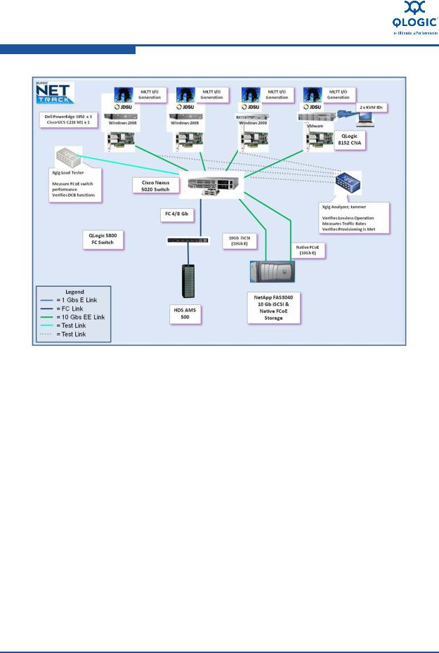
Figure 3-1 illustrates the unified Ethernet infrastructure enhanced with DCB. FCoE and iSCSI storage traffic was tested and validated with LAN traffic, which shared the unified 10GbE bandwidth driven by Converged Network Adapters. JDSU testing tools were installed in the fabric, either in-line or at the edge, with hardware and software to test and certify system-level behavior. These tools also provided expert-system support that simplified troubleshooting and reduced installation time.
51031-00 B |
3-1 |
3–Architecture
Reference Architecture Description
Figure 3-1. Reference Architecture Diagram
3-2 |
51031-00 B |

3–Architecture Reference Architecture Description
Equipment Details
Table 3-1 lists the referenced architecture equipment. Table 3-2 lists the JDSU Xgig equipment and testing software.
Table 3-1. Converged Network Equipment Inventory
Quantity |
Product |
Model |
|
Number |
|||
|
|
||
|
|
|
|
3 |
Dell® PowerEdge® servers a |
1950 |
|
4 |
QLogic QLE8142 adapters (server connectivity) |
QLE8142 |
|
|
|
|
|
1 |
Cisco UCS general-purpose rack-mount server |
UCS C210 M1 |
|
|
Windows® 2008 |
|
|
1 |
Cisco UCS high-density rack-mount server |
UCS C200 M1 |
|
|
Windows 2008 |
|
|
|
|
|
|
1 |
NetApp® FAS3040 storage system |
FAS3040 |
|
|
(10Gb iSCSI storage and 10Gb native FCoE storage) |
|
|
|
|
|
|
1 |
HDS® AMS500 Storage Array |
AMS500 |
|
|
(4Gb Fibre Channel storage) |
|
|
|
|
|
|
1 |
QLogic 5800V 8Gb Fibre Channel switch |
SB5802V |
|
|
(Fibre Channel connection) |
|
|
|
|
|
|
1 |
Cisco Nexus™ 5020 FCoE switch |
Nexus 5020 |
|
|
(unified fabric interconnect) |
|
|
|
|
|
aTwo Windows 2008, one VMware® ESX™ with one Windows 2008 and Red Hat® Enterprise Linux guest with Microsoft® iSCSI initiator. All servers use the QLogic QLE8142 adapter.
Table 3-2. JDSU Converged Network Validation Equipment
Product |
Model/Part |
|
Number |
||
|
||
|
|
|
Xgig four-slot chassis |
Xgig-C042 |
|
|
|
|
10GbE/10G Fibre Channel multi-functional blade |
Xgig-B2100C |
|
|
|
|
Four-port, 1, 2, 4, 8Gbps Fibre Channel Analyzer blade |
Xgig-B480FA |
|
|
|
|
Two-port, Xgig 10GbE Fibre Channel Analyzer function key |
Xgig-2FG10G1-SW |
|
|
|
|
Two-port, 10GE Analyzer and Jammer function key |
Xgig-S20JFE |
|
|
|
|
Two-port, 10GEE FCoE Analyzer and Load Tester function key |
Xgig-S20LEA |
|
|
|
|
Four-port, 1, 2, 4, 8Gbps Fibre Channel Analyzer function key |
Xgig-S48AFA |
|
|
|
51031-00 B |
3-3 |

3–Architecture
Reference Architecture Description
|
|
|
|
3-4 |
51031-00 B |

4 Installation
This section describes how to set up an FCoE environment. It assumes a general understanding of SAN administration concepts.
Determine Configuration
QLogic FCoE adapters are supported on multiple hardware platforms and operating systems. Generally, the following specifications apply, but you should always check the QLogic Web site for current information. This configuration uses a subset of the following equipment:
Server bus interface—PCIe® Gen1 x8 or PCIe Gen2 x4
Hardware platforms—IA32 (x86), Intel64, AMD64 (x64), IA64, SPARC®, PowerPC®
Operating systems—Windows Server® 2003, 2008, 2008 R2 (targeted); Red Hat EL AP 5.x; Novell® SLES 10.x, 11; VMware ESX/ESXi 3.5 and 4.0; Solaris® 10, OpenSolaris™. This list can be found under the specifications tab for QLogic adapters on the QLogic Web site.
Storage—The following storage systems are in most data centers:
Fibre Channel
iSCSI
FCoE (NetApp)
Switches—The following switches are typical in this configuration:
Fibre Channel
FCoE
Ethernet
Cabling
Fiber optic cable (OM2/OM3) between servers, switches, and storage
Cat5e and Cat6 Ethernet for device management and 1GbE iSCSI storage
51031-00 B |
4-1 |

4–Installation
Equipment Installation and Configuration
Equipment Installation and Configuration
This section focuses on the converged network installation and configuration. You do not have to change your current storage and network management practices.
Install the Converged Network Adapter Hardware
Begin by identifying a pilot server that meets Converged Network Adapter hardware requirements (PCI slot type, length, available slot) and install the adapters.
To install the adapter hardware:
1.Use a ground strap to avoid damaging the card or server.
2.Power off the computer and disconnect the power cable.
3.Remove the computer cover, and find an empty PCIe x8 bus slot (Gen1) or PCIe x4 bus slot (Gen2).
4.Pull out the slot cover (if any) by removing the screw or releasing the lever.
5.Install the low-profile bracket, if required.
6.Grasp the adapter by the top edge, and then insert it firmly into the appropriate slot.
7.Refasten the adapter's retaining bracket using the existing screw or lever.
8.Close the computer cover.
9.Plug the appropriate Ethernet cable (either copper or optical) into the adapter.
Optical models ship with optical transceivers installed. QLogic 8100 Series adapters used for this project operate only with optical transceivers sold by QLogic.
The list of approved copper cables is available at the following link: http://www.qlogic.com/Products/ConvergedNetworking/ConvergedNet workAdapters/Pages/CopperCables.aspx.
10.Plug in the power cable, and turn on the computer.
4-2 |
51031-00 B |
4–Installation Equipment Installation and Configuration
Install the Adapter Drivers
To install the FCoE and Ethernet drivers:
1.Go to the QLogic Driver Downloads/Documentation page (Figure 4-1) at http://driverdownloads.qlogic.com/QLogicDriverDownloads_UI/default.aspx.
Figure 4-1. Driver Download Page Model Selection
2.In the table at the bottom of the page, select Converged Network Adapters, the adapter model, your operating system, and then click Go.
3.On the download page under Drivers, select the driver and download it to your system.
4.Follow the included instructions for installing the downloaded driver.
51031-00 B |
4-3 |

4–Installation
Equipment Installation and Configuration
Install SANsurfer FC HBA Manager
To install SANsurfer® FC HBA Manager:
1.Go to the QLogic Driver Downloads/Documentation page at http://driverdownloads.qlogic.com/QLogicDriverDownloads_UI/default.aspx.
2.In the table at the bottom of the page (Figure 4-2), select Converged Network Adapters, the adapter model, your operating system, and then click Go.
Figure 4-2. Driver Download Page Driver Link
3.On the download page under Management Tools (Figure 4-3), select SANsurfer FC HBA Manager and download it to your system.
Figure 4-3. Driver Download Page Driver and Documentation
4.Follow the included instructions for installing the downloaded software.
4-4 |
51031-00 B |

4–Installation Equipment Installation and Configuration
Cabling
To connect the Fibre Channel and Ethernet cables:
1.Connect the Fibre Channel cables from the servers to the Cisco FCoE Nexus switch.
2.Connect the Fibre Channel cables from the storage to the Cisco FCoE Nexus switch.
3.Connect any necessary Ethernet cables for device management and iSCSI storage.
Fibre Channel Switches
If you are connecting Fibre Channel devices, such as storage, through a Fibre Channel switch, then you must connect the Fibre Channel switch to a Fibre Channel port on the FCoE switch.
In addition, set up a zoning configuration so that the servers can discover the disk LUNs you are mapping. Refer to the Fibre Channel switch documentation for zoning instructions.
FCoE Switches
QLogic and Cisco have jointly developed the QLogic and Cisco FCoE Design Guide for implementing a unified data center using Cisco Nexus 5000 Series switches and QLogic second-generation Converged Network Adapters. Refer to the design guide for detailed instructions on how to implement an FCoE network and configure the Cisco Nexus switch and QLogic adapters (Cisco and QLogic, 2010). The design guide also describes how to configure N_Port ID Virtualization (NPIV) to resolve fabric expansion concerns related to domain IDs. The QLogic and Cisco FCoE Design Guide does not describe the configuration of the PFC and ETS DCB parameters, which will be required for the tests described in this document.
For information about configuring DCB on a Cisco Nexus 5000 Series switch, see “Configuring DCB on a Nexus Switch” on page 4-6; some variables may need to be adjusted for your configuration.
51031-00 B |
4-5 |
 Loading...