


 Loading...
User Manual for Commercial Series Net DVR
Commercial Series Net DVR
User Manual
(V2.0)
Thank you for purchasing our embedded Net DVR. This manual is applicable for QSD42208, QSC26408, and QSC26416 Net DVR, as well as the QSF2648008 and QSF2648016 Enterprise DVR models. Please read this User Manual carefully to ensure that you can use the device correctly and safely.
DISCLAIMER: The contents of this Manual are subject to change without notice; we are also not responsible for typing errors or errors of omission.
Contact Us:
Q-See Products
8015 E. Crystal Dr
Anaheim, CA 92807
Website:
http://www.q-see.com
Customer Service:
Phone: 877-998-3440 x 538
Email: cs@dpsi-usa.com
Tech Support:
Phone: 877-998-3440 x 539
Email: ts@dpsi-usa.com
Fax:
714-998-3509
Rev 082907D
Page 1 Total 121

User Manual for Commercial Series Net DVR
|
Index |
|
Version Description........................................................................................................................... |
4 |
|
Chapter 1 |
Product Introduction.................................................................................................. |
6 |
1.1 |
Summary ................................................................................................................... |
6 |
1.2 |
Features ..................................................................................................................... |
6 |
Chapter 2 |
Installation................................................................................................................. |
8 |
2.1 |
Checking the DVR and Its Accessories..................................................................... |
8 |
2.2 |
HDD Installation ....................................................................................................... |
8 |
2.3 |
Rear Panel Description.............................................................................................. |
9 |
2.3.1 |
8-ch QSD42208 Rear Panel .............................................................................. |
9 |
2.3.2 |
8-ch/16-ch QSC26408/16 Rear Panel ............................................................. |
10 |
2.4 |
External Alarm In/Out Connection ......................................................................... |
12 |
Chapter 3 |
Operational Instructions .......................................................................................... |
13 |
3.1.1 |
8-ch QSD42208 Front Panel ................................................................................... |
13 |
3.1.2 |
8-ch QSC26408 Front Panel ................................................................................... |
15 |
3.1.3 |
16-ch QSC26416 Front Panel ................................................................................. |
17 |
3.2 |
Remote Control ....................................................................................................... |
19 |
3.3 |
Menu Description.................................................................................................... |
21 |
3.3.1 |
Menu Items...................................................................................................... |
21 |
3.3.2 |
Menu Operation .............................................................................................. |
22 |
3.4 |
Character Input........................................................................................................ |
25 |
Chapter 4 |
Basic Operation Guide ............................................................................................ |
26 |
4.1 |
Power on ................................................................................................................. |
26 |
4.2 |
Preview.................................................................................................................... |
26 |
4.3 |
User name and password......................................................................................... |
29 |
4.4 |
PTZ Control ............................................................................................................ |
31 |
4.5 |
Manual Record ........................................................................................................ |
33 |
4.6 |
Playback .................................................................................................................. |
34 |
4.7 |
Backup Recorded Files ........................................................................................... |
39 |
4.8 |
Shut Down DVR ..................................................................................................... |
41 |
Chapter 5 |
Main and Aux Output Function............................................................................... |
43 |
5.1 |
Main and aux output................................................................................................ |
43 |
5.2 |
Main and Aux output preview................................................................................. |
44 |
5.3 |
Main and Aux output playback ............................................................................... |
47 |
5.4 |
Main or Aux output to control PTZ......................................................................... |
48 |
Chapter 6 |
Parameters Setup Guide .......................................................................................... |
49 |
6.1 |
Administrator and Password ................................................................................... |
49 |
6.2 |
Add and Delete User ............................................................................................... |
51 |
6.3 |
Unit Name and Device ID....................................................................................... |
54 |
6.4 |
Video Output Standard and VGA Setup.................................................................. |
55 |
6.5 |
OSD Setup............................................................................................................... |
56 |
6.6 |
Video Parameters Setup .......................................................................................... |
59 |
|
Page 2 Total 121 |
|

User Manual for Commercial Series Net DVR
6.7 |
Mask Area Setup ..................................................................................................... |
60 |
6.8 |
View Tampering Alarm ........................................................................................... |
62 |
6.9 |
Video Loss Alarm.................................................................................................... |
64 |
6.10 |
Motion Detection Alarm ......................................................................................... |
66 |
6.11 |
Preview Properties .................................................................................................. |
69 |
6.12 |
Recording Setup ...................................................................................................... |
71 |
6.13 |
External Alarm Input and Relay Output.................................................................. |
75 |
6.14 |
Network Parameters ................................................................................................ |
79 |
6.141 |
Accessing the DVR over a network ...................................................................... |
81 |
6.142 |
Accessing the DVR from a remote computer ....................................................... |
82 |
6.15 |
PTZ ......................................................................................................................... |
83 |
6.16 |
RS232 setup ............................................................................................................ |
87 |
6.17 |
Exceptions ............................................................................................................... |
92 |
6.18 |
Transaction Information .......................................................................................... |
93 |
Chapter 7 |
Utilities.................................................................................................................... |
97 |
7.1 |
Save Parameters ...................................................................................................... |
97 |
7.2 |
Restore Parameters.................................................................................................. |
97 |
7.3 |
Upgrade................................................................................................................... |
98 |
7.4 |
Hard Disk Management .......................................................................................... |
99 |
7.5 |
Clear Alarm Out ...................................................................................................... |
99 |
7.6 |
Reboot ..................................................................................................................... |
99 |
7.7 |
Power Off................................................................................................................ |
99 |
7.8 |
View Log................................................................................................................. |
99 |
7.9 |
System Information............................................................................................... |
102 |
Chapter 8 |
Firmware Upgrade ................................................................................................ |
103 |
8.1 |
FTP Server Setup .................................................................................................. |
103 |
8.2 |
Upgrade Mode....................................................................................................... |
105 |
Appendix A |
HDD Capacity Calculation............................................................................ |
106 |
Appendix B |
DVR Connect Cable Definition .................................................................... |
107 |
1 How to make a RS-485 connect cable .......................................................................... |
107 |
|
2 How to make a UTP network connect cable ................................................................. |
107 |
|
3 How to make a RS-232 connect cable .......................................................................... |
109 |
|
Appendix C |
Specifications ................................................................................................ |
112 |
Appendix D |
Quick Search Function Table ........................................................................ |
115 |
Appendix E |
Troubleshooting ........................................................................................... |
117 |
Appendix F |
Product Service ............................................................................................ |
119 |
Appendix G |
Customer Information Card .......................................................................... |
120 |
Page 3 Total 121

User Manual for Commercial Series Net DVR
Version Description
Version 2.0 built 070206:
The new version firmware DVR has the following new features:
1.Supports USB mouse
Recommended USB mouse model list: Logitech: M-UV83
Benq: M800 ViewSonic: MC204 Philips: SPM4500BB/93 LG: LGIM-ML208 GlodFly: GF-OP718
Newmen: MS0270 (www.newmen.com.cn) Agiler: AGM-018LU (www.agilertech.com) Citu: CH-3090 (www.citu.cn)
2.Supports USB external DVD backup
Recommended USB external DVD model list: LG GSA-E10L
BENQ EW164B Samsung SE-S164
3.Supports DS-1000KI network keyboard
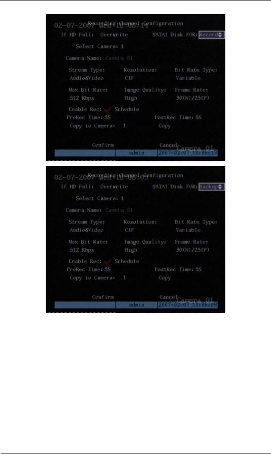
4.Supports E-SATA HDD backup
E-SATA interface in QSD42208, QSC26408, and QSC26416 model DVRs is optional. 1st internal SATA interface can be extended to E-SATA (external SATA) interface. In DVR “Recording” menu, you can select 1st SATA HDD as either “Recording” or “Backup” work mode.
Page 4 Total 121
User Manual for Commercial Series Net DVR
If you select “Backup” mode, in DVR “Playback” menu, you can select SATA HDD for backup.
5 Solved some old version bugs
VGA black screen and Aux audio output issues
Page 5 Total 121

User Manual for Commercial Series Net DVR
Chapter 1 Product Introduction
1.1Summary
The Commercial series network digital video recorder is an excellent digital surveillance product. It uses the embedded MCU and embedded operating system (RTOS), combining the most advanced technology in the Information Industry such as video and audio encoding/decoding, hard disk recording and TCP/IP. The firmware is burned into flash memory, more stable and reliable.
The Commercial series device has both the features of digital video recorder (DVR) and digital video server (DVS). It can work stand alone, also be used to build a powerful surveillance network, widely used in banking, telecommunications, transportation, factories, warehouses, irrigation, etc.
1.2Features
Compression
•Supports 16 channnels video input (PAL/NTSC) at most. Each channel is independent, H.264 hardware compression and real time (PAL: 25 FPS, NTSC: 30FPS). Support both variable bitrate and variable frame rate.
•Supports 16 channels audio input at most. Each channel is independent, OggVorbis compression and bitrate is 16Kbps.
•Compressed video and audio are synchronous. You can select either mixed stream or only video stream.
•Supports 4CIF, DCIF, 2CIF, CIF and QCIF resolution (depending on model).
•Supports multi area motion detection.
•Supports OSD and changeable OSD position.
•Supports LOGO and changeable LOGO position.
Local functions
Record
•Supports multiple record type, including real time, manual record, motion detection, external alarm, motion&alarm, motion|alarm.
•Supports 8 SATA HDDs and each HDD can support 2000GB maximum.
•Supports FAT32 file system.
•Supports HDD S.M.A.R.T technology.
•Supports cycle or none cycle record.
•Supports backing up the recorded files and clips. Supports USB flash memory, USB HDD, USB CD-R/W, USB DVD-R/W, SATA DVDRW/CDRW HDD for backup.
Page 6 Total 121

User Manual for Commercial Series Net DVR
Preview and playback
•Supports BNC analog moniotor and VGA output for main output
•Supports one aux video and audio input
•Supports multiple preview modes.
•Supports sensitive area mask.
•Supports camera spiteful block alarm.
•Supports 2-ch synchronous playback. Support play forward, backward, pause, frame by frame, etc.
•Supports play back by files or by time.
•Displays local record status.
PTZ
•Supports many PTZ protocols.
•Supports preset, sequence and cruise.
Alarms
•Supports exception alarm, motion detection alarm, external alarm, etc.
Others
•Supports IR control.
•Supports RS-485 keyboard.
•Supports multi-level user management.
Network
•Supports TCP, UDP, RTP, Multicast for network preview.
•Supports PPPoE for broad band access.
•Supports PSTN for narrow band access.
•Supports remote parameters setup.
•Alarm information can be sent to remote center.
•Network control PTZ.
•Network record real time stream.
•Network download and playback of the recorded files in DVR.
•Remotely upgrade the firmware.
•RS-232 supports transparent channel function so that the remote PC can use DVR to control serial devices.
•Supports bi-directional voice talk or one-way voice broadcast.
•Supports IE to preview and config DVR.
•Support log.
Development support
•Provides network SDK.
•Provides client demo source code.
Page 7 Total 121

User Manual for Commercial Series Net DVR
Chapter 2 Installation
Warning: Before you install the DVR, please make sure the power to the DVR is
switched off.
2.1Checking the DVR and Its Accessories
When you get the product, check that all the items are included in your product package. There is a list in the package. If any of the items are missing, please contact your dealer.
2.2HDD Installation
Installation notice
The DVR has no HDD when leaving factory. Based on the record schedule, you can calculate the total capacity you need (refer to Appendix A). Please ask the specialist to disassembly the DVR and install HDD. If the vendor you purchased the DVR from did not include a HDD have HDD installed by qualified technicians.
Installation instrument
One Phillips screw driver.
HDD installation
1.Open the DVR box.
2.Take off the HDD mounting plate.
3.Place the HDD on the mounting plate and attach it with screws.
4.Attach the mounting plate in the DVR.
5.Connect the ATA data cable correctly.
6.Plug the HDD power connector into the HDD.
7.Cover and re-attach the DVR box lid.
Note: After you install the HDDs, you must format them. Please refer to section 6.4. If your vendor supplied the DVR with HDDs this may have already been done for you.
Page 8 Total 121
User Manual for Commercial Series Net DVR
2.3Rear Panel Description
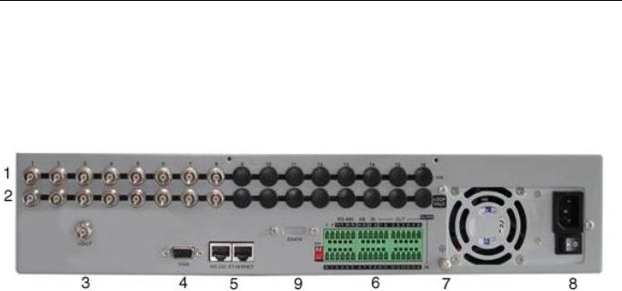
2.3.1 8-ch QSD42208 Rear Panel
|
Index |
Physical Interface |
Description |
||
|
|
|
|
|
|
1 |
Video Input |
Standard BNC. |
|||
|
|
|
|||
|
|
|
|||
|
|
|
|
|
|
2 |
Loop Back Ports |
Standard BNC. |
|||
|
|
|
|||
|
|
|
|||
|
|
|
|
|
|
3 |
Main video Output |
Connect CCTV monitor, output video and menu. |
|||
|
|
|
|||
|
|
|
|||
|
|
|
|
|
|
4 |
VGA Interface |
VGA display. |
|||
|
|
|
|
|
|
|
|
|
|
|
|
5 |
RS-232/Keyboard |
Connect RS-232 devices. Refer to Appendix B for pin |
|||
Interface |
definition. |
||||
|
|
||||
|
|
RJ45 Ethernet Port |
Connect network devices. Refer to Appendix B for pin |
||
|
|
definition. |
|||
|
|
|
|||
|
|
Keyboard Interface |
Can use Hikvision DS-1000K1, DS-1002K1, DS1003K1 |
||
|
|
|
|
|
|
6 |
RS-485 |
PTZ connection. Using T+/T- to connect PTZ. |
|||
|
|
|
|||
External Alarm Input |
4 sensor alarm in. |
||||
|
|
||||
|
|
|
|
|
|
|
|
Relay Output |
2 replay output. |
||
|
|
|
|
|
|
7 |
GND |
Ground |
|||
|
|
|
|
|
|
8 |
AC Input |
100~240VAC |
|||
|
|
|
|
|
|
9 |
E-SATA |
Optional. Extend 1st internal SATA to E-SATA. |
|||
|
|
|
|
|
|
|
|
|
|
|
|
Page 9 Total 121

User Manual for Commercial Series Net DVR
2.3.2 8-ch/16-ch QSC26408/16 Rear Panel
QSC26408 Rear Panel
|
|
|
|
|
|
|
|
|
|
|
|
|
|
|
|
|
|
|
|
|
|
|
|
|
|
|
|
|
|
|
|
|
|
|
|
|
|
|
|
|
|
|
|
|
|
|
|
|
|
|
|
|
|
|
|
|
|
|
|
|
|
|
|
|
|
|
|
|
|
|
|
|
|
|
|
|
|
|
|
|
|
|
|
|
|
|
|
|
|
|
|
|
|
|
|
|
|
|
|
|
|
|
|
|
|
|
|
|
|
|
|
|
|
|
|
|
|
|
|
|
|
|
|
|
|
|
|
|
|
|
|
|
|
|
|
|
|
|
|
|
|
|
|
|
|
|
|
|
|
|
|
|
|
|
|
|
|
|
|
|
|
|
|
|
|
|
|
|
|
|
|
|
|
|
|
|
|
|
|
|
|
|
|
|
|
|
|
|
|
|
|
|
|
|
|
|
|
|
|
|
|
|
|
|
|
|
|
|
|
|
|
|
|
|
|
|
|
|
|
|
|
|
|
|
|
|
|
|
|
|
|
|
|
|
|
|
|
|
|
|
|
|
|
|
|
|
|
|
|
|
|
|
|
|
|
|
|
|
|
|
|
|
|
|
|
|
|
|
|
|
|
|
|
|
|
|
|
|
|
|
|
|
|
|
|
|
|
|
|
|
|
|
|
|
|
|
|
|
|
|
|
|
|
|
|
|
|
|
|
|
|
|
|
|
|
|
|
|
|
|
|
|
|
|
|
|
|
|
|
|
|
|
|
|
|
|
|
|
|
|
|
|
|
|
|
|
|
|
|
|
|
|
|
|
|
|
|
|
|
|
|
|
|
|
|
|
|
|
|
|
|
|
|
|
|
|
|
|
|
|
|
|
|
|
|
|
|
|
|
|
|
|
|
|
|
|
|
|
|
|
|
|
|
|
|
|
|
|
|
|
|
|
|
|
|
|
|
|
|
|
|
|
|
|
|
|
|
|
|
|
|
|
|
|
|
|
|
|
|
|
|
|
|
|
|
|
|
|
|
|
|
|
|
|
|
|
|
|
|
|
|
|
|
|
|
|
|
|
|
|
|
|
|
|
|
|
|
|
|
|
|
|
|
|
|
|
|
|
|
|
|
|
|
|
|
|
|
|
|
|
|
|
|
|
|
|
|
|
|
|
|
|
|
|
|
|
QSC26416 Rear Panel |
|
|
|
|
||||||||||||||||||
|
|
|
|
|
|
|
|
|
|
|
|
|
|
|
|
|
|
|
|
|
|
|
|
||||||||||||
Index |
|
Physical Interface |
|
|
|
|
|
|
|
|
|
|
Description |
|
|
|
|
|
|||||||||||||||||
|
|
|
|
|
|
|
|
|
|
|
|
|
|
|
|
|
|
|
|||||||||||||||||
1 |
|
|
|
|
Video Input |
|
Standard BNC. |
|
|
|
|
|
|
||||||||||||||||||||||
|
|
|
|
|
|
|
|
|
|
|
|
|
|
|
|
|
|
|
|
|
|
|
|
|
|
|
|
|
|
|
|
|
|
||
|
|
|
|
Audio Input |
|
Standard BNC. |
|
|
|
|
|
|
|||||||||||||||||||||||
|
|
|
|
|
|
|
|
|
|
|
|
||||||||||||||||||||||||
|
|
|
|
|
|
|
|
|
|
|
|
|
|
|
|
|
|
|
|||||||||||||||||
2 |
|
|
|
|
Aux video Output |
|
Spot monitor for video preview and playback. |
|
|
|
|
|
|
||||||||||||||||||||||
|
|
|
|
|
|
|
|
|
|
|
|
|
|
|
|
|
|
|
|
|
|
|
|
|
|
|
|
|
|
|
|
|
|
||
|
|
|
|
Aux audio Output |
|
Spot monitor for audio preview and playback. |
|
|
|
|
|
|
|||||||||||||||||||||||
|
|
|
|
|
|
|
|
|
|
|
|
||||||||||||||||||||||||
|
|
|
|
|
|
|
|
|
|
|
|
|
|
|
|
|
|
|
|||||||||||||||||
3 |
|
|
|
|
Main video output |
|
Main monitor for video and menu. |
|
|
|
|
|
|
||||||||||||||||||||||
|
|
|
|
|
|
|
|
|
|
|
|
|
|
|
|
|
|
|
|
|
|
|
|
|
|
|
|
|
|
|
|
|
|
||
|
|
|
|
Main audio output |
|
Main monitor for audio preview and playback. |
|
|
|
|
|
|
|||||||||||||||||||||||
|
|
|
|
|
|
|
|
|
|
|
|
||||||||||||||||||||||||
|
|
|
|
|
|
|
|
|
|
|
|
|
|
|
|
|
|
|
|||||||||||||||||
4 |
|
|
|
|
Line In |
|
Audio line input for voice talk. |
|
|
|
|
|
|
||||||||||||||||||||||
|
|
|
|
|
|
|
|
|
|
|
|
|
|
|
|
|
|
|
|||||||||||||||||
5 |
|
|
|
|
VGA Interface |
|
VGA display. |
|
|
|
|
|
|
||||||||||||||||||||||
|
|
|
|
|
|
|
|
|
|
|
|
|
|
|
|
|
|
|
|
|
|||||||||||||||
6 |
|
|
|
|
RS-232 |
|
Connect RS-232 devices. Refer to Appendix B for pin |
|
|
|
|
|
|
||||||||||||||||||||||
|
|
|
|
|
definition. |
|
|
|
|
|
|
||||||||||||||||||||||||
|
|
|
|
|
|
|
|
|
|
|
|
|
|
|
|
||||||||||||||||||||
|
|
|
|
|
|
|
|
|
|
|
|
|
|
|
|
|
|
|
|
|
|
|
|
|
|
|
|
|
|
|
|
|
|
|
|
Page 10 Total 121
User Manual for Commercial Series Net DVR
|
RJ45 Network Port |
Connect network devices. Refer to Appendix B for pin |
|
|
definition. |
||
|
|
||
7 |
USB Interface |
USB memory disk, USB HDD, USB CD-R/W, USB DVD |
|
or USB mouse. |
|||
|
|
||
8 |
E-SATA |
Optional. Extend 1st internal SATA to E-SATA. |
|
|
|
|
|
9 |
SW1 |
RS-485 terminal resistor switch. Default is off. The |
|
resistor is 120Ohm. |
|||
|
|
||
|
RS-485 |
PTZ connection. Using T+/T- to connect PTZ. |
|
|
|
|
|
|
Keyboard Interface |
Using D+/D- for keyboard and DVR cascade connection. |
|
10 |
Can use Hikvision DS-1000K1, DS-1002K1, DS1003K1 |
||
|
|||
|
External Alarm Input |
16 sensor alarm in. |
|
|
|
|
|
|
Relay Output |
4 replay output. |
|
|
|
|
|
11 |
GND |
Ground |
|
|
|
|
|
12 |
AC Input |
100~240VAC |
|
|
|
|
Page 11 Total 121
User Manual for Commercial Series Net DVR
2.4External Alarm In/Out Connection
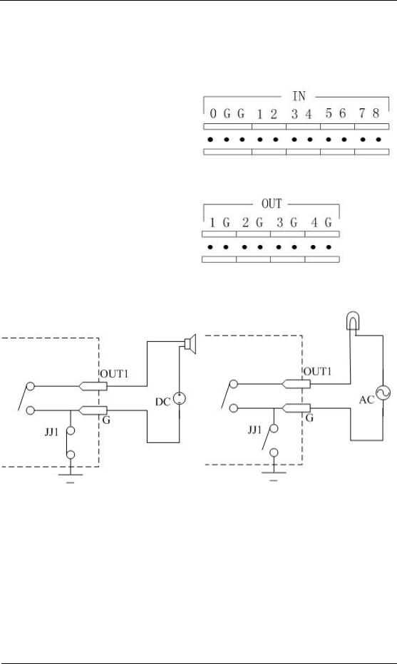
Alarm input port (drp node):
G (GND): Connect the GND of sensor.
1~8: Alarm input, support normal open/normal close.
0: Reserved.
Alarm output: 1G~4G: 4 relay output.
Alarm output connection
Please note the usage of jumper JJ1. If you use DC, either connection is OK. We suggest you use DC under 12V, 1A.
If you use AC, please open the jumper. There are 4 jumpers (JJ1, JJ2, JJ3 and JJ4) on DVR main board, corresponding with 4 alarm output. The default is closed.
Warning: If you use AC input for relay output, please open the jumpers.
Page 12 Total 121

User Manual for Commercial Series Net DVR
Chapter 3 Operational Instructions
3.1.18-ch QSD42208 Front Panel
Index |
Type |
Name |
|
Description |
|
|
|
|
|
1 |
USB Port |
|
USB flash drive, HDD, DVDRW/CDRW or Mouse |
|
|
|
|
|
|
2 |
Status |
1-8 |
Shows channel 1-8 status. Green means recording; Red means |
|
|
Lamps |
|
network transmission; Orange means recording and network |
|
|
|
|
transmission. Lamp twinkle and red means the corresponding |
|
|
|
|
HDD has error. |
|
|
|
|
|
|
3 |
POWER |
POWER |
Device switch with power indicator lamp. Green means DVR is |
|
|
|
|
working; Red means DVR is powered off; No light means no |
|
|
|
|
power is supplied. |
|
|
|
|
|
|
4 |
Compound |
MENU |
1. |
Switch preview mode into menu; |
|
Keys |
|
2. |
Brush control short key WIPER . |
|
|
ESC |
||
|
|
|
|
|
|
|
PLAY |
Cancel and back to parent menu. |
|
|
|
|
1. |
Local playback; |
|
|
REC |
2. |
AUTO in PTZ mode. |
|
|
|
||
|
|
EDIT |
1. |
Manual record; |
|
|
|
2. |
SHOT in PTZ mode (adjust preset). |
|
|
PTZ |
1. |
In edit state, delete current cursor character; |
|
|
A |
2. |
IRIS+ in PTZ control; |
|
|
|
|
|
|
|
|
1. |
Select ü or × to enable or disable. |
|
|
|
1. |
Enter into PTZ control mode; |
|
|
|
|
|
Page 13 Total 121

User Manual for Commercial Series Net DVR
|
|
PREV |
2. |
IRISin PTZ control. |
|
|
|
||
|
|
|
1. |
Input switch (number, lower case, upper case and symbol); |
|
|
INFO |
2. |
FOCUS+ in PTZ control; |
|
|
Main/Aux |
||
|
|
|
|
|
|
|
|
3. |
In preview mode, display or hide the channel status bar. |
|
|
|
1. |
Multi screen preview switch; |
|
|
|
2. |
Switch menu mode into preview; |
|
|
|
3. |
FOCUSin PTZ control. |
|
|
|
ZOOM+ in PTZ control. |
|
|
|
|
1. |
ZOOMin PTZ control. |
|
|
|
2. |
Switch main/aux video output control mode. |
5 |
Input |
Numeric |
Input number, lower case, upper case character and symbols. |
|
|
Keys |
Keys |
|
|
|
|
F1 |
LIGHT in PTZ control. |
|
|
|
F2 |
||
|
|
|
|
|
|
|
|
AUX in PTZ control. |
|
|
|
|
|
|
6 |
Control |
Direction |
Composed of á , â , ß and à . |
|
|
Keys |
Keys |
||
|
|
|
||
|
|
|
1. |
Menu mode, use ß / à to select á / â to |
|
|
|
edit; |
|
|
|
ENTER |
2. |
PTZ direction control; |
|
|
|
3. |
Playback speed control. |
|
|
|
1. |
Menu confirmation; |
|
|
|
2. |
Select ü or × to enable or disable; |
|
|
|
3. |
Pause playback. |
|
|
|
|
|
|
|
|
|
|
|
|
|
|
|
Page 14 Total 121
User Manual for Commercial Series Net DVR
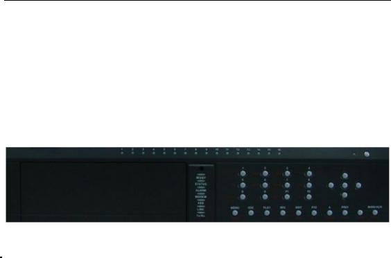
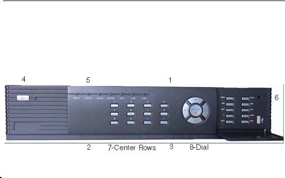
3.1.28-ch QSC26408 Front Panel
|
|
|
|
|
|
|
|
|
|
|
|
|
|
|
|
|
|
|
|
Index |
Type |
Name |
Description |
|
|
|
|
|
|
|
|
|
|
|
|
1 |
|
|
IR receiver. |
|
|
|
|
|
|
|
|
|||
|
2 |
Status |
1-8 |
Shows channel 1-8 status. Green means recording; Red means |
|||
|
|
Lamps |
|
network transmission; Orange means recording and network |
|||
|
|
|
|
transmission. Lamp twinkle and red means the corresponding |
|||
|
|
|
|
HDD has error. |
|
|
|
|
3 |
Status |
9-16 |
Shows channel 1-16 status. Green means recording; Red means |
|||
|
|
Lamps |
(Previous |
network transmission; Orange means recording and network |
|||
|
|
|
model |
transmission. |
|
|
|
|
|
|
QSC26416) |
|
|
|
|
|
|
|
|
|
|||
|
4 |
POWER |
POWER |
Device switch with power indicator lamp. Green means DVR is |
|||
|
|
|
|
working; Red means DVR is powered off; No light means no |
|||
|
|
|
|
power is supplied. |
|
|
|
|
|
|
|
|
|
|
|
|
5 |
Status |
READY |
DVR is ready. |
|
|
|
|
|
Lamps |
STATUS |
Green means you can use IR remote control. |
|
|
|
|
|
|
ALARM |
Red means there is an alarm. |
|
|
|
|
|
|
MODEM |
Green means modem connection and dial-up successful. |
|||
|
|
|
HDD |
Twinkle in red means reading or writing HDD. |
|
|
|
|
|
|
LINK |
Green means network is OK. |
|
|
|
|
|
|
Tx/Rx |
Twinkle in green means data is being transmitted. |
|
|
|
|
|
|
|
|
|
|
|
|
6 |
Command |
MENU |
1. Switch preview mode into menu; |
|
|
|
|
|
Keys |
|
2. Brush control short key WIPER . |
|
|
|
|
|
|
|
|
|
||
|
|
|
ESC |
Cancel and back to parent menu. |
|
|
|
|
|
|
PLAY |
|
|
|
|
|
|
|
|
|
|
|
|
|
|
|
|
|
|
|
|
|
|
|
|
Page 15 Total 121 |
|
|
|

User Manual for Commercial Series Net DVR
1. Local playback 2. AUTO in PTZ mode.
REC
|
|
|
1. |
Manual record; |
|
|
EDIT |
2. |
SHOT in PTZ mode (adjust preset). |
|
|
|
||
|
|
|
1. |
In edit state, delete current cursor character; |
|
|
PTZ |
2. |
IRIS+ in PTZ control; |
|
|
|
||
|
|
A |
2. |
Select ü or × to enable or disable. |
|
|
|
||
|
|
|
1. |
Enter into PTZ control mode; |
|
|
PREV |
2. |
IRISin PTZ control. |
|
|
|
|
|
|
|
|
1. |
Input switch (number, lower case, upper case and symbol); |
|
|
INFO |
2. |
FOCUS+ in PTZ control; |
|
|
|
|
|
|
|
Main/Aux |
3. |
In preview mode, display or hide the channel status bar. |
|
|
|
1. |
Multi screen preview switch; |
|
|
|
2. |
Switch menu mode into preview; |
|
|
|
3. |
FOCUSin PTZ control. |
|
|
|
ZOOM+ in PTZ control. |
|
|
|
|
3. |
ZOOMin PTZ control. |
|
|
|
4. |
Switch main/aux video output control mode |
|
|
|
|
|
7 |
Input |
Numeric |
Input number, lower case, upper case character and symbols. |
|
|
Keys |
Keys |
|
|
|
|
F1 |
LIGHT in PTZ control. AUX in PTZ control. |
|
|
|
F2 |
||
|
|
|
|
|
|
|
|
|
|
|
Control |
Direction |
Composed of á , â , ß and à . |
|
|
Keys |
Keys |
||
|
|
|
||
|
|
|
1. |
Menu mode, use ß / à to select á / â to |
|
|
|
edit; |
|
|
|
ENTER |
2. |
PTZ direction control; |
|
|
|
3. |
Playback speed control. |
|
|
|
1. |
Menu confirmation; |
|
|
|
2. |
Select ü or × to enable or disable; |
|
|
|
3. |
Pause playback. |
Page 16 Total 121
User Manual for Commercial Series Net DVR
3.1.316-ch QSC26416 Front Panel
|
Index |
Type |
Name |
|
Description |
|
|
|
|
|
|
|
|
|
1 |
|
|
IR receiver. |
|
|
|
|
|
|
|
|
|
|
2 |
Status |
1-8 |
Shows channel 1-8 status. Green means recording; Red means |
|
|
|
|
Lamps |
|
network transmission; Orange means recording and network |
|
|
|
|
|
|
transmission. Lamp twinkle and red means the corresponding |
|
|
|
|
|
|
HDD has error. |
|
|
|
|
|
|
|
|
|
|
3 |
Status |
9-16 |
Shows channel 1-16 status. Green means recording; Red means |
|
|
|
|
Lamps |
|
network transmission; Orange means recording and network |
|
|
|
|
|
|
transmission. |
|
|
|
|
|
|
|
|
|
|
4 |
POWER |
POWER |
Device switch with power indicator lamp. Green means DVR is |
|
|
|
|
|
|
working; Red means DVR is powered off; No light means no |
|
|
|
|
|
|
power is supplied. |
|
|
|
|
|
|
|
|
|
|
5 |
Status |
READY |
DVR is ready. |
|
|
|
|
Lamps |
STATUS |
Green means you can use IR remote control. |
|
|
|
|
|
ALARM |
Red means there is an alarm. |
|
|
|
|
|
MODEM |
Green means modem connection and dial-up successful. |
|
|
|
|
|
HDD |
Twinkle in red means reading or writing HDD. |
|
|
|
|
|
LINK |
Green means network is OK. |
|
|
|
|
|
Tx/Rx |
Twinkle in green means data is being transmitted. |
|
|
|
6 |
Command |
MENU |
1. |
Switch preview mode into menu; |
|
|
|
Keys |
|
2. |
Brush control short key WIPER . |
|
|
|
|
ESC |
|
||
|
|
|
|
|
|
|
|
|
|
PLAY |
Cancel and back to parent menu. |
|
|
|
|
|
|
1. |
Local playback; |
|
|
|
|
REC |
2. AUTO in PTZ mode. |
|
|
|
|
|
|
|
||
|
|
|
|
|
|
|
|
|
|
|
|
|
|
|
|
|
|
|
Page 17 Total 121 |
|

User Manual for Commercial Series Net DVR
|
|
EDIT |
1. |
Manual record; |
|
|
|
2. |
SHOT in PTZ mode (adjust preset). |
|
|
PTZ |
1. |
In edit state, delete current cursor character; |
|
|
A |
2. |
IRIS+ in PTZ control; |
|
|
|
|
|
|
|
|
3. |
Select ü or × to enable or disable. |
|
|
|
1. |
Enter into PTZ control mode; |
|
|
PREV |
2. |
IRISin PTZ control. |
|
|
|
||
|
|
|
1. |
Input switch (number, lower case, upper case and symbol); |
|
|
INFO |
2. |
FOCUS+ in PTZ control; |
|
|
Main/Aux |
||
|
|
|
|
|
|
|
|
3. |
In preview mode, display or hide the channel status bar. |
|
|
|
1. |
Multi screen preview switch; |
|
|
|
2. |
Switch menu mode into preview; |
|
|
|
3. |
FOCUSin PTZ control. |
|
|
|
ZOOM+ in PTZ control. |
|
|
|
|
5. |
ZOOMin PTZ control. |
|
|
|
6. |
Switch main/aux video output control mode. |
|
|
|
|
|
7 |
Input |
Numeric |
Input number, lower case, upper case character and symbols. |
|
|
Keys |
Keys |
|
|
|
|
F1 |
LIGHT in PTZ control. |
|
|
|
F2 |
||
|
|
|
|
|
|
|
|
AUX in PTZ control. |
|
|
|
|
|
|
8 |
Control |
Direction |
Composed of á , â , ß and à . |
|
|
Keys |
Keys |
||
|
|
|
||
|
|
|
1. |
Menu mode, use ß / à to select á / â to edit; |
|
|
|
2. |
PTZ direction control; |
|
|
ENTER |
3. |
Playback speed control. |
|
|
|
1. |
Menu confirmation; 2. Select ü or × to enable or disable; |
|
|
|
3. |
Pause playback. |
|
|
|
|
|
Page 18 Total 121

User Manual for Commercial Series Net DVR
3.2Remote Control
Index |
Name |
Description |
|
|
|
|
|
1 |
POWER |
Turnoff device. |
|
|
|
|
|
2 |
DEV |
Enable/Disable IR remote control |
|
|
|
|
|
3 |
Numeric Keys |
Same as numeric keys of front panel. |
|
|
|
|
|
4 |
EDIT |
Same as EDIT key of front panel. |
|
|
|
|
|
5 |
A |
Same as A key of front panel. |
|
|
|
|
|
6 |
REC |
Same as REC key of front panel. |
|
|
|
|
|
7 |
PLAY |
Same as PLAY key of front panel. |
|
|
|
|
|
8 |
INFO |
Same as INFO key of front panel. |
|
|
|
|
|
9 |
VOIP |
Same as [Main/Aux] key of front |
|
panel. |
|||
|
|
||
|
|
|
|
10 |
MENU |
Same as MENU key of front panel. |
|
|
|
|
|
11 |
PREV |
Same as PREV key of front panel. |
|
|
|
|
|
12 |
Direction Keys |
Same as direction keys and enter key of |
|
ENTER |
front panel. |
||
|
Page 19 Total 121

User Manual for Commercial Series Net DVR
13 |
PTZ |
Same PTZ key of front panel. |
|
|
|
|
|
14 |
ESC |
Same as ESC key of front panel. |
|
|
|
|
|
15 |
Reserved |
|
|
|
|
|
|
16 |
F1 |
Same as F1 key of front panel. |
|
|
|
|
|
17 |
Lens control |
IRIS, FOCUS ZOOM for lens control |
|
of PTZ camera. |
|||
|
|
||
|
|
|
|
18 |
F2 |
Same as F2 key of front panel. |
|
|
|
|
Loading the batteries into the Remote Control
1.Remove the battery cover.
2.Insert the battery. Please make sure the poles (+ and -) are correctly positioned.
3.Replace the battery cover.
Start to use the Remote Control
Press DEV key, input the DVR device ID (default is “88”, can be changed in “Display”
menu) and then press ENTER key. If the “STATUS” lamp of DVR front panel turns to green, it means you can use IR controller to operate this DVR.
Stop using the Remote Control
When remote control status is on, press DEV key again, the “STATUS” lamp will be turned off, then the remote control can not control this DVR.
Switch the DVR off
When remote control status is on, press POWER key for several seconds, the DVR will be powered off.
When the Remote Control can not work normally
•Check batteries pole positions.
•Check the remaining charge in the batteries.
•Check to see the remote control sensor is covered. If the problem is still exists, please contact administrator.
Page 20 Total 121
User Manual for Commercial Series Net DVR
3.3Menu Description
3.3.1 Menu Items
Menu Name |
Function |
|
Menu Name |
Function |
|
|
|
|
|
|
|
|
|
|
|
|
|
|
Camera name and position setup |
|
|
Video standard |
|
|
|
Adjust Brightness, Contrast, |
Hue |
|
Brightness |
|
|
|
and Saturation |
|
|
Menu transparency |
|
|
OSD Display mode, position and |
||
|
Unit name |
|
|
|
OSD format setup |
|
Display |
Device ID |
|
|
Image |
Mask area setup |
|
|
Require password |
|
|
View tampering area and response |
||
|
Screen saver time |
|
|
setup |
|
|
|
VGA resolution |
|
|
|
Video signal loss |
|
|
Date and Time |
|
|
|
Motion detection sensitivity, |
area |
|
|
|
|
|
and response setup |
|
|
|
|
|
|
||
|
Overwrite/Stop recording |
|
DVR IP address |
|
||
|
Resolution |
and |
recording |
|
DNS IP |
|
Recording |
parameters setup |
|
Network |
Multicast IP address |
|
|
|
Record schedule |
|
|
Remote host IP and port |
|
|
|
PreRecord time |
|
|
|
NAS IP and directory |
|
|
PostRecord time |
|
|
PPPoE username and password |
|
|
|
|
|
|
|
||
|
Alarm input type (Normal open/ |
|
|
|
||
Alarms |
Normal close) |
|
|
Exceptions |
Exceptions type |
|
|
Alarm response and PTZ linkage |
|
Exceptions response |
|
||
|
Alarm output and schedule |
|
|
|
||
|
|
|
|
|
|
|
|
PTZ parameters |
|
|
|
|
|
PTZ |
Preset setup |
|
|
RS232 |
RS232 parameters |
|
|
Sequence setup |
|
|
|
RS232 work mode |
|
|
Cruise setup |
|
|
|
|
|
|
|
|
|
|
|
|
|
Preview mode |
|
|
User |
Add or delete user |
|
Preview |
Switch time |
|
|
Password setup or modification |
|
|
|
|
Password |
|
|||
|
Enable/Disable audio preview |
User rights setup |
|
|||
|
|
|
||||
|
Preview layout |
|
|
|
|
|
|
|
|
|
|
|
|
Page 21 Total 121

User Manual for Commercial Series Net DVR
|
|
|
Restore parameters |
|
|
|
Upgrade firmware |
|
Text input mode |
|
HDD management |
Transaction |
ATM IP address |
Utilities |
Clear alarm output |
|
ATM type |
|
Reboot |
|
Text information |
|
Power off |
|
|
|
View log |
|
|
|
System information |
|
|
|
|
3.3.2 Menu Operation
How to enter into menu mode
•Press MENU key to enter into DVR main menu.
•Press PLAY short key to enter into playback menu.
•Perss REC short key to enter into manual record menu.
•Perss PTZ short key to enter into PTZ control interface.
Notes: You must input user name and password. The default user name is “admin” and password is “12345”.
Main Menu Description
The main menu interface is:
There is one rectanglar frame called “Active Frame”. It can be moved from one icon to
another by using à or ß key. When the “Active Frame” is located on an icon, you can press
Page 22 Total 121

User Manual for Commercial Series Net DVR
ENTER key to enter into the secondary menu. For example, move the “Active Frame” to the
“Image” icon, press ENTER to enter into the secondary menu show below:
Each menu contains different kinds of items. There is a rectangular frame called “Active
Frame” which is pointing to the selected item. This “Active Frame” can be moved by à or ß keys. There are such kinds of menu items:
a)Check Box: Provide 2 options, “ü” means enable and “×” means disable. You can use
ENTER or EDIT key to switch over.
b)List Box: Provides more than 2 options. However, only one of them can be selected. You can use ↑ and ↓ to select one option. For example, on the right side of “Select Camera”, there is a list box for you to select one camera.
c)Edit Box: This is for you to input characters. Press EDIT key to enter into edit status, you can input characters as follows:
i.Press A key to select number, upper case, lower case or symbols;
ii.Use à and ß keys to move cursor;
iii.Use EDIT key to delete the charcter in front of cursor;
iv.Press ENTER or ESC to exit edit.
d)Button: Excute a special function or enter into next sub-menu. For example, press “Policy” button to enter into sub-menu. Press Confirm to save parameters and return
Page 23 Total 121

User Manual for Commercial Series Net DVR
to parent menu. Press Cancel button to cancel and return to parent menu. The button in grey means it can be operated only after it is enabled.
How to exit menu
Press PREV key to exit menu and return to preview mode.
Page 24 Total 121

User Manual for Commercial Series Net DVR
3.4Character Input
In the menu interface, if you enter into edit status (for example, in the “camera name” edit box), at the bottom of screen, the input status appears:
Here you can press numeric keys to input digital numbers.
Press A key to change input methods. You can select “number”, “Uppercase”, “Lowercase”
or “Symbol”.
Uppercase
Lowercase
Symbol
There are 24 symbols in all. They are divided into 4 pages, and you can use 0 key to go to the
next page.
Page 25 Total 121

User Manual for Commercial Series Net DVR
Chapter 4 Basic Operation Guide
4.1Power on
Note: Please make sure the power supply matches DVR and AC cable is connected correctly. Before switching DVR on, please connect one monitor with VOUT or VGA interface. Otherwise, you can not see graphic user interface and can not operate.
If POWER lamp is off, please check the following:
Step1: Connect AC cable correctly;
Step2: Switch on the power button on the rear panel.
If POWER lamp is in red, just press POWER button to start DVR.
When DVR is started, POWER lamp is green. On the monitor or VGA display, DSP and HDD initialization process will be shown.
The first line represents DSP initialization. If the DSP icon is “×”, it means that the DSP has
an initialization error, please contact administrator at once.
The second line represents HDD initialization. Icons of SATA hard drives are displayed. If the HDD icon has a “×”, it means the corresponding HDD is not installed or not detected. If the HDD is installed but not detected, please contact administrator.
Note: If HDD is not installed or not detected, DVR will beep for alarm. You can disable the alarm option in “Exceptions” menu.
4.2Preview
DVR will enter into preview mode after it is started.
On preview screen, you can see date, time, camera name and camera status icon.
Set system date and time in “Display” menu, refer to section 5.2.9; Change camera name in “Image” menu, refer to section 5.3.2.
In the screen, it will display record and alarm status of each camera. These two kinds of status will switch over automatically.
Page 26 Total 121

User Manual for Commercial Series Net DVR
Press A key to display or hide the camera status bar.
Camera record status is:
Icon |
Icon Color |
Status Description |
|
|
|
|
White |
No video signal |
|
|
|
|
Yellow |
Vdieo input |
|
|
|
|
Pink |
Manual recording |
|
|
|
|
Green |
Real time recording |
|
|
|
|
Blue |
Motion detect recording |
|
|
|
|
Red |
External alarm recording |
|
|
|
Page 27 Total 121

User Manual for Commercial Series Net DVR
Camera alarm status is:
Icon |
Icon Color |
Status Description |
|
|
|
|
White |
Video signal lost |
|
|
|
|
Yellow |
View tampering alarm |
|
|
|
|
Pink |
Motion&External alarm |
|
|
|
|
Green |
No alarm |
|
|
|
|
Blue |
Motion alarm |
|
|
|
|
Red |
External alarm |
|
|
|
Press numeric keys to switch to individual camera preview. If DVR has less than 10 channels,
press one numeric key to switch corresponding channel. For example, press 2 key to preview 2nd camera. If DVR has 10 or more than 10 channels, press two numeric keys to switch to
corresponding channel. For example, press 0 2 to preview 2nd camera; and press 1
2 keys to preview 12th camera.
Press EDIT key to manually cycle preview. You can set the auto preview mode in “Preview” menu, refer to section 5.11.
Press PREV key to switch multi-screen perview.
Page 28 Total 121
User Manual for Commercial Series Net DVR
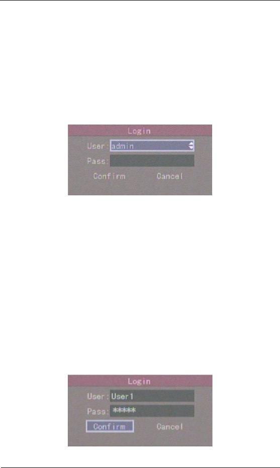
4.3User name and password
Note: When DVR is delivered from factory, there is only one default administrator named “admin”, and password is “12345”. The administrator’s name can not be modified, while the password can be modified. The administrator can create 15 users and define their user rights.
Login
Login dialog box:
Use á / â keys to select one user, perss à key to enter into “Password” edit box, input
corresponding password, press ENTER key to exit edit box. The “Active Frame” will be moved
to “Confirm” button. Press ENTER key to enter into main menu. If there is beeper alarm, it
means the user name and password do not match. After three incorrect trys the DVR will enter into preview mode.
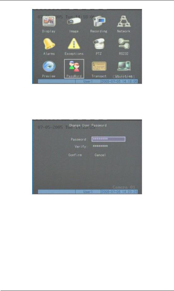
Modify password
For those users created by admin, they can modify their password as follows:
Step1: Enter into main menu
Press MENU key, in the login dialog, select your user name, input the correct password, you can enter into the main menu.
Page 29 Total 121
User Manual for Commercial Series Net DVR
Setp 2: Enter into password modification menu
Move the “Active Frame” to “Password” icon by using à / ß keys. Press ENTER key to enter into password menu:
Step 3: Input new password
Press EDIT key to enter into edit box. You can use numeric keys to input new password.
The password can be null. It also can be 16 numerals. Press ENTER to exit edit box, and move to “Verify” item to input the new password for verification.
Note: In edit box, use à / ß to move cursor and EDIT key to delete the numeral
in front of the cursor.
Step 4: Modify password successfully
Move the “Active Frame” to “Confirm” button, press ENTER key. If the password is
Page 30 Total 121
Loading...