


 Loading...
User Manual
MODEL QC40108
H.264 NETWORK DVR
Variable CIF and D1 Recording Options
Thank You for Choosing a Q-See Product!
All of our products are backed by a conditional service warranty covering all hardware for 12 months from the date of purchase. Additionally, our products also come with a free exchange policy that covers all manufacturing defects for one month from the date of purchase. Permanent upgrading service is provided for the software and is available at www.Q-See.com.
Be certain to make the most of your warranty by completing the registration form online. In addition to warranty and technical support benefits, you’ll receive notifications of product updates along with free downloadable firmware updates for your DVR. Register today at www.Q-See.com!
Please see the back of this manual for exclusions.
© 2011 Q-See. Reproduction in whole or in part without written permission is prohibited. All rights reserved. This manual and software and hardware described herein, in whole or in part, may not be reproduced, translated, or reduced to any machine-readable form without prior
written approval.
Trademarks: All brand names and products are trademarks or registered trademarks of their respective owners.
Q-See is a registered trademark of DPS, Inc.
Disclaimer: The information in this document is subject to change without notice. The manufacturer makes no representations or warranties, either express or implied, of any kind with respect to completeness of its contents.
Manufacturer shall not be liable for any damages whatsoever from misuse of this product.
2
About this Manual
This manual is written for the QC40108 DVR and was accurate at the time it was completed. However, because of our ongoing effort to constantly improve our products, and the different capabilities of the two models additional features and functions may have been added since that time and on-screen displays may change. We encourage you to visit our website at www.Q-see.com to check for the latest firmware updates and product announcements.
This manual covers the setup and local operation of the DVR. Instructions for configuring the DVR for remote access, along with instructions for monitoring the DVR using a computer or mobile device, are contained within the Remote Monitoring Guide which is included on the CD that accompanied your DVR and which can also be found on www.Q-See.com.
Throughout the manual we have highlighted warnings and other important information that will assist you in operating your new system in a safe and trouble-free manner. Please take the time to read and follow all instructions and pay attention to alerts as shown below:
IMPORTANT! Red boxes with this icon indicate warnings. To prevent possible injury or damage to the product, read all warnings before use.
NOTE! Text in blue boxes with the Information icon offer additional guidance and explanations about how to make the most out of your system.
Version 1.0 4/18/11
3

TABLE OF CONTENTS
1. INTRODUCTION |
7 |
|
2. INSTALLATION AND CONNECTION |
10 |
|
2.1 |
DVR Installation |
10 |
2.2 |
Connections |
10 |
3. CONTROLS |
14 |
|
3.1 |
Mouse Control |
14 |
Virtual Keyboard |
15 |
|
3.2 |
Remote Control |
16 |
3.3 |
Front and Side Panels |
18 |
4. BASIC OPERATION |
19 |
|
4.1 |
Operation |
19 |
4.2 |
Live View |
19 |
4.3 Login, Logout and Main Menu |
20 |
|
Login |
20 |
|
Main Menu |
21 |
|
Shortcut Menu |
21 |
|
Logout |
22 |
|
Auto Resume |
22 |
|
4.4 |
Recording |
22 |
Manual Recording |
22 |
|
4.5 Search and Playback |
23 |
|
Search |
24 |
|
Playback |
25 |
|
4.6 |
Schedule |
28 |
4.7 |
Motion, Video Loss and Camera Masking Detection |
29 |
Motion Detection |
29 |
|
Video Loss |
30 |
|
Camera Masking |
30 |
|
Event Response |
30 |
|
4.8 Backup |
32 |
|
5. MENUS |
34 |
5.1 Main Menu |
35 |
5.2 Info Menu |
35 |
HDD Information |
35 |
BPS |
36 |
Log |
36 |
Version |
37 |
Online Users |
37 |
5.3 Setting Menu |
38 |
General |
38 |
Encode |
40 |
Schedule |
43 |
RS232 |
43 |
Network |
43 |
Default |
45 |
5.4 Advanced |
46 |
HDD Manage |
46 |
Abnormality |
47 |
Record |
48 |
Account |
48 |
Auto Maintain |
48 |
TV Adjust |
49 |
5.5 Backup |
49 |
5.6 Shutdown |
49 |
6. PAN/TILT/ZOOM CAMERAS |
50 |
6.1 Connecting a PTZ Camera |
50 |
6.2 PTZ Control and Setup |
51 |
Setup |
51 |
Control |
52 |
Setting Preset/Patrol/Pattern/Scan |
52 |
Running PTZ Functions |
54 |
7. ALARMS |
55 |
|
7.1 |
Alarm Input |
55 |
7.2 |
Alarm Output |
56 |
7.3 |
Alarm Setup and Activation |
57 |
4 |
5 |

8. HARD DISK DRIVE |
59 |
|
8.1 |
Installation/Removal |
59 |
8.2 |
Calculating the Recording Capacity of a Hard disk Drive |
61 |
APPENDIX |
62 |
|
Troubleshooting |
62 |
|
Minimum Computer Configuration |
65 |
|
Q-SEE PRODUCT WARRANTY |
66 |
|
Questions or Comments? Contact Us |
67 |
|
INTRODUCTION |
CHAPTER 1 |
To prevent damage to your Q-See product or injury to yourself or to others, read and understand the following safety precautions in their entirety before installing or using this equipment. Keep these safety instructions where all those who use the product will read them.
WARNING! ELECTRIC SHOCK RISK!
nCheck the unit and any accessories included in the package immediately after opening. If items are missing or damaged, repackage and return to the point of purchase.
nUse the proper power source. Only use the power adapter supplied with your system. Do not use this product with a power source that applies more than the specified voltage (100240V AC).
nNever insert anything metallic into the DVR. Inserting anything into the DVR or its case can be a source of dangerous electric shock.
nDo not operate in dusty areas. Avoid placing the DVR in places that are dusty.
nDo not expose this product to rain or use near water. If this product accidentally gets wet, unplug it and contact an authorized dealer immediately.
nKeep product surfaces clean and dry. To clean the outside case of the DVR, gently wipe using a lightly dampened cloth (only use water, do not use solvents).
nDo not operate this DVR without the cover securely in place. Do not attempt to do any repairs to the DVR yourself. If there are unusual sounds or smells coming from the DVR, unplug it immediately and contact Q-See technical support. Under no circumstances should the cover be removed while the device is connected to a power source. You should only remove the cover to install/replace the hard disk drive (See Chapter 8) or replace the standard 3v lithium cell battery on the motherboard. These are the only user serviceable parts. You may need to replace the battery if the internal clock resets itself after a power outage
nHandle DVR box carefully. If you accidentally drop your DVR on any hard surface, it may cause a malfunction. If the DVR doesn’t work properly due to physical damage, contact an authorized dealer for repair or exchange.
nMake sure there is proper air circulation around the unit. This DVR system uses a hard drive for video storage which generates heat during operation. Do not block air holes located on the bottom, top, sides and back of the DVR as they are designed to keep the system cool while running. Install or place this product in an area where there is ample air circulation.
nProvide proper ventilation. This DVR has a built-in fan that properly ventilates the system. Do not cover or impede this fan.
6 |
7 |

FEATURES AND SPECIFICATIONS
This combo DVR integrates a DVR (Digital Video Recorder) and LCD screen together. It is an excellent digital monitor with a sleek appearance and innovative capabilities which are functional and reliable.
It uses an embedded Linux OS to maintain stable operation and a popular H.264 compression algorithm to produce high quality low bit stream footage that is easy to manage and efficient to transfer over the internet. It can use various functions such as record, playback, and monitoring at the same time and produces audio and video synchronization. This product has advanced technology and strong network data transmission functions.
This combo DVR utilizes a high quality LCD capable of producing rich and vivid images. It’s convenient 10-inch screen allows flexible viewing capabilities. This is an ideal system that can be used in an in-home environment and a variety of business environments that require enhanced monitoring capabilities such as: super markets, convenience stores, transportation, etc.
This product offers the following features:
Smartphone Compatible
Access live footage directly from your iPhone, or other Smartphone. Your DVR can also be set to e-mail your hand held-device whenever specific activity occurs, such as motion detection.
View Your Video Feed Online with No Service Fees
View your DVR’s live or recorded video footage on any Internet accessible computer with Internet Explorer, Mozilla Firefox and Google Chrome (using IE plug-in).
Stay Notified with Customizable Email Alerts
Set your system up to notify you when an event has occurred at the location you are monitoring. Notification alerts can easily be adjusted to your specifications.
Advanced Motion Detection Activated Recording
Advanced motion detection settings ensure that false alarms are not triggered. The easy to use motion detect set up screen allows you to mask out certain areas which experience heavy movement in order to avoid false alarms and avoid unnecessary record triggering.
Multiple Backup Options
A built-in USB port gives you the option of backing up and transferring your video footage using a flash drive or external USB hard drive. You can also connect to an external CD/ DVD writer to burn your file footage right onto a compact disc or DVD disc. Files can also be accessed from your DVR system to a remote computer location by logging on remotely.
Connect to a TV or PC Monitor Easily
This system comes uses an BNC video out port to allow you to connect to a TV or computer monitor for viewing purposes.
User-Friendly LCD Control Functions
Side panel button control allows instant booting up and system shut down at the press of a button. LCD monitor can be set to go into energy efficient stand-by mode.
Included Mouse and Remote Control
The system can be booted up and shut down using the included remote control or mouse. Mouse operation function supports intelligent operation by enabling copy and paste functions.
Storage Function
Encrypted file format to ensure data security and avoid vicious data modification.
Compression Format
Supports multiple-channel audio and video. Independent hardware decodes the audio and video signal from each channel to maintain video and audio synchronization.
24/7 Scheduled Recording
Choose which days of the week and hours of the day you want to set your DVR to record or not record.
Multiple Playback Options and Advanced Search Functions
Supports real-time recording on each channel independently. Search through recorded files while you are playing live footage, monitoring through a remote location using a supported internet browsing application and backing up system files. A variety of playback modes include: slow play, fast play, backward play and frame by frame play.
Network Monitoring
Supports network remote real-time monitoring (available bandwidth permitting), remote record search and remote PTZ control.
Alarm Activation Function
Several relay alarm outputs enable you to pair your system with an on-site alarm system.
Communication Ports
sRS485 port can be used for PTZ camera control.
sRS232 port can connect to a keyboard for central control, and can also connect to PC COM to upgrade system and maintain system settings.
sStandard Ethernet port allows you to access the DVR from a network or the Internet.
PTZ camera control
sSupports PTZ decoder via RS485.
sSupports a variety of protocols to allow the DVR to control the PTZ speed dome: AD1641M, Admatrix, Banknote, DH-CC440, DH-Matrix, DH-SDI, Dh-SD2, Eptz, General, Haiyu, Hy, Lilin, Mercer-1, Panasonic, PE5051K, Pelco-9750, PelcoASCII, PelcoD, Pelcod-DON, PelcoD-S, Pelco-SI, Pelco-T, PelcoD1, PelcoD1-T, PelcoP, PelcoP-HK, PelcoP1, PelcoP5, Philips, Pih-717, QT-2XXD, Rm110a, Sae, Samsung, Sanli, Santachi, Sharp, Sony, WV-CS850I, WV-CS850II, WV-CS950, Yaan
NOTE! Depending on your point of purchase, your DVR may have the hard disk drive already installed. If your drive was packaged separately, or if you wish to upgrade your installed drive up to a 500GB drive, please see Chapter 8 at the back of this manual which covers installing the drive.
8 |
9 |
INSTALLATION AND |
CHAPTER 2 |
CONNECTION |
|
Please note that it is important to keep in mind common safety guidelines when installing your DVR or connecting additional devices – including turning off and unplugging your DVR before installing internal components.
2.1 DVR INSTALLATION
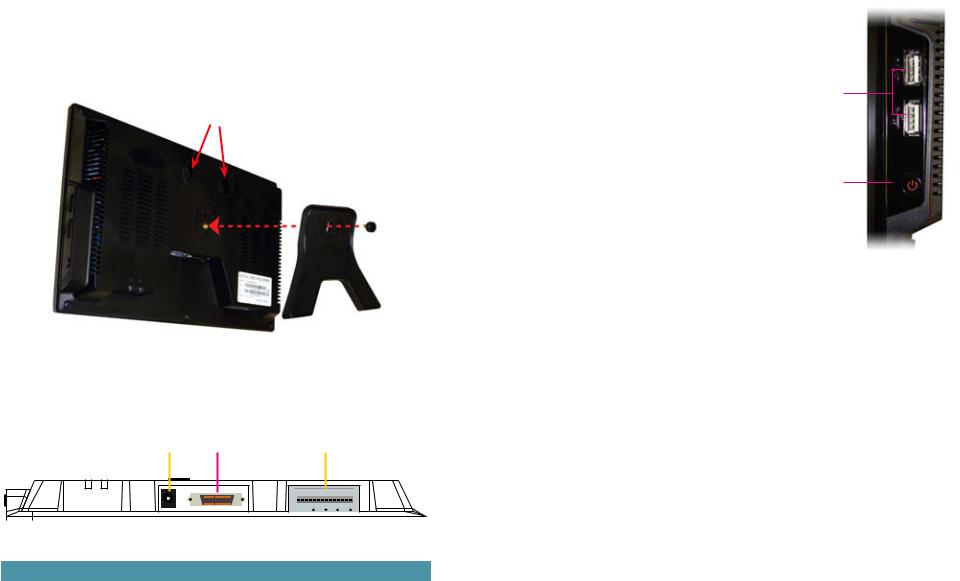
This DVR can be mounted on the included stand or it can be wall-mounted using a pair of screws (not included).
Holes for Wall Mount
PICTURE 2-1
2.2 CONNECTIONS
As part of its compact design, the connection ports on this DVR are concentrated on a panel on the back of the device located above the stand. These ports allow you to connect the mouse, cameras and network cable along with additional input and output components such as alarms, pan-tilt-zoom (PTZ) cameras, additional monitors and so on.
|
|
|
|
|
|
|
|
|
|
|
|
|
1 |
2 |
3 |
4 |
5 |
|
|||||||
|
|
|
|
|
|
|
|
|
|
|
|
|
|
|
|
|
|
|
|
|
|
|
|
|
|
|
|
|
|
|
|
|
|
|
|
|
|
|
|
|
|
|
|
|
|
|
|
|
|
|
|
|
|
|
|
|
|
|
|
|
|
|
|
|
|
|
|
|
|
|
|
|
|
|
|
|
|
|
|
|
DC 12V |
AUDIO/VIDEO/NET |
|
|
|
1 2 3 4 NO C A B Rx Tx |
|
|||
|
|
|
|
|
|
|
|
|
|
|
|
|
|
|
|
|
|
|
|
|
|
|
|
|
|
|
|
|
|
PICTURE 2-2 |
|
|
|
|
|
|
||
|
|
|
|
|
|
|
|
|||||
|
|
Item |
Description |
|
Item |
|
Description |
|||||
|
|
|
|
|
|
|
||||||
|
|
1 |
Network Connection Indicator Light |
2 |
|
Network Activity Status Light |
||||||
|
|
|
|
|
|
|
|
|||||
|
|
3 |
DC Power Input |
|
4 |
|
Audio, Video and Network |
|||||
|
|
|
|
|
|
|
Connection Port (via dongle) |
|||||
|
|
|
|
|
|
|
|
|
|
|
|
|
|
|
5 |
RS232 and RS485 Ports, Alarm Input and Output |
|
|
|
|
|
|
|||
|
|
|
|
|
|
|
|
|
|
|
|
|
RS485 Port
The connection, configuration and operation of PTZ cameras will be covered in Chapter 6 PTZ Cameras while the connection and configuration of alarms – both incoming and outgoing – will be covered in Chapter 7.
Side Panel
In addition to the ports located on the underside of the DVR, there are twin USB ports located on the right side of the monitor frame. Either one can be used for the included USB mouse.
In addition, either port can be used to upload firmware updates or to back up files by inserting a USB flash drive into the port. Please see Version in Section 5.2 and Backup in Section 5.5, respectively for instructions on performing these operations.
Power
USB
Ports
Power
Switch
PICTURE 2-3
The DVR’s power supply plugs into the socket (Item number 3 in Picture 2-2) located on the underside of the unit. It is absolutely essential that you only use the power supply that came with the DVR to ensure proper operation and to avoid damage.
We also recommend that you use an uninterrupted power supply (UPS) so that the system will continue to operate in the event of a power loss. In addition, you should connect the DVR into a UL-1449 rated surge protector. It should have a joule rating of at least 400, a response time of 10 nanoseconds or less and a clamping voltage of no more than 330 volts.
To turn on the DVR, you will need to use the Power button located below the USB ports on the right side of the DVR. When the DVR is off, pushing on the button will cause the DVR to initialize and power up.
When the DVR is operating, briefly pressing the Power button will cause the screen to go to sleep until the button is pressed again. The DVR will still operate normally - including recording. If you hold the button longer, a Shut Down progress bar will display. Releasing the
button before the bar completes will put the monitor to sleep as above. If you allow the bar to progress all the way, the DVR will ask you to enter your password to confirm and then will shut down. Afterwards, the DVR can be restarted in the normal fashion.
10 |
11 |
Cameras
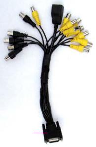
Conventional CCD or CMOS cameras are connected to the DVR through the Audio/ Video/Network port (Item number 4 in Picture 2-2) via the dongle included with the system. The dongle shown in Picture 2-4 has eight Video In plugs (yellow) for cameras and four audio input plugs (black). The extra yellow and black plugs are Video Out and Audio Out respectively.
The dongle also includes an female port for an RJ45 connection. Also known as an Ethernet cable, this is used to connect
your DVR to the Internet through a router or modem.
Audio In |
Audio and |
RJ45 |
Video In |
||||
BNC |
Video Out |
(Ethernet) |
BNC |
||||
Connectors |
BNC |
Port |
Connectors |
||||
|
|
Connectors |
|
|
|
|
|
|
|
|
|
|
|
||
|
|
|
|
|
|
|
|
|
|
|
|
|
|
|
|
|
|
|
|
|
|
|
|
|
|
|
|
|
|
|
|
Connector to Audio/Video/ Network Port on DVR
PICTURE 2-4
The cameras and the dongle use BNC connectors. Each lead is identified with its channel number.
The cameras will also need to be connected to a power supply – whether the power supply included with the cameras or a power distribution panel. For best results, both the DVR and the camera power supply(ies) should share the same electrical grounding.
For cable runs longer than 200 feet, cable runs within walls, or in areas where there is electromagnetic interference, you should use high-quality shielded RG59 cable. RG6 cable should be used for runs exceeding 800 feet and fiber optic cable should be used when distances exceed 1,800 feet. In circumstances requiring cameras to be positioned over 200 feet from the DVR, the camera’s power supply should be located closer to the camera.
Video Output
This DVR supports video output to a TV or a monitor using the Video Out connector on the dongle. The BNC Video Out lead on the dongle is labeled as such. For output through the dongle, you will need to use a BNC to RCA adapter to connect to a TV with RCA inputs and a signal converter box to connect to a VGA monitor or a television with VGA inputs.
Audio Input and Output
Audio input and output is also handled through the BNC dongle. Each channel, including the output channel, is labeled on the lead itself. To receive audio signals, you must have a camera with built-in microphone or a separate microphone located near the camera.
Normal output through the BNC audio out channel is usually over 200mv 1KΩ. It can directly connect to an active sound box or amplified speaker.
12 |
13 |
CONTROLS |
CHAPTER 3 |
This DVR can be controlled through the USB mouse or with the remote control. We have found that the majority of our customers prefer to operate their DVRs using the USB mouse because of its ease of use and flexibility and our manual is set up with this in mind. For your convenience, we also include a remote control which allows you to perform most of the day-to-day functions from a distance. It functions as a typical remote control with additional buttons allowing you to navigate through menus and control functions. We recommend that you configure your DVR using the mouse controls, reserving the remote control for operations such as live viewing, file search and playback. For the purposes of this manual, instructions will be given for using the mouse but the other modes are also presented in this chapter.
3.1 MOUSE CONTROL
The mouse operates in a manner similar to how it is used on a conventional computer; point- and-click, right-click, double click and so on. How these functions are used is based on the context of where they are used. Some examples are:
LEFT CLICK: |
Selecting an item |
|
|
|
|
Opening a menu |
|
|
|
|
Checking a box or motion detection status |
|
|
|
|
Selecting letters, numbers or symbols on the virtual keyboard. |
|||
DOUBLE CLICK: |
Selecting an event for playback |
|
|
|
|
Selecting a screen to zoom into from multi-screen mode |
|||
RIGHT CLICK |
Exits any window. Exits |
|
|
|
|
View 1 |
|||
|
any menu or reopens |
|
||
|
previous menu. |
|
View 4 |
|
|
Opens Pop-Up |
|
View 9 |
|
|
Shortcut Menu |
|
View 16 |
|
|
|
|
Pan/Tilt/Zoom |
|
|
|
|
Color Setting |
|
|
|
|
Search |
|
|
|
|
Record |
|
|
|
|
Alarm Output |
|
|
|
|
Alarm Input |
|
MOUSE WHEEL |
Page up or page down |
|
Main Menu |
|
|
Switch items in check box |
|
PICTURE 3-1 |
|
|
Increase or decrease numerical value in numerical input box |
|||
CLICK-AND-DRAG |
Select motion detection zone |
|
|
|
|
Select privacy mask zone |
|
|
|
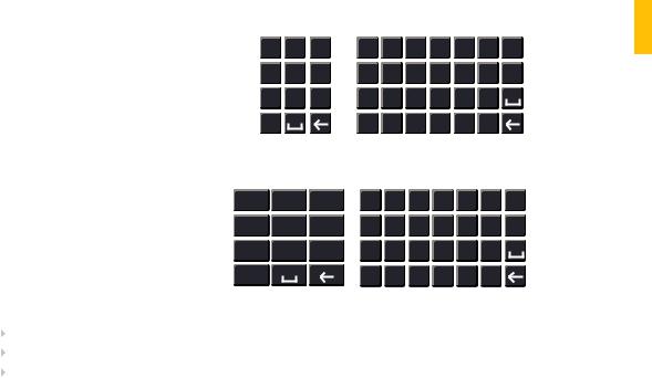
VIRTUAL KEYBOARD
The virtual keyboard is contextual. For example, it will only show digits when the field is for numeral entries. In fields where letters and symbols can be entered, users can switch between various formats – numbers, upper case, lower case and symbols – by selecting the white keyboard symbol that will appear to the right of a field where text can be entered. The symbol itself will change to show which keyboard format is available next.
Available keyboards include:
|
1 2 |
3 |
|
|
a |
b |
c |
d |
e |
f g |
|
|
|
4 |
5 |
6 |
|
|
h |
i |
j |
k |
l |
m n |
|
|
7 |
8 |
9 |
|
|
o |
p |
q |
r |
s |
t |
|
|
0 |
|
|
|
|
u |
v w x |
y |
z |
|
||
|
NUMBERS |
|
|
|
LOWER CASE |
|
||||||
|
|
|
|
|
|
|
|
LETTERS |
|
|
||
|
|
|
||||||||||
1 / 2 : 3 . |
|
A B C D E F G |
|
|||||||||
4 ? 5 - 6 _ |
|
H I J K L M N |
|
|||||||||
7 @ 8 # 9% |
|
O P Q R S T |
|
|||||||||
0 & |
|
|
|
|
U V W X Y Z |
|
||||||
|
SYMBOLS |
|
|
|
UPPER CASE |
|
||||||
|
|
|
|
|
|
|
|
LETTERS |
|
|
||
PICTURE 3-2
The keyboards are used by clicking on the desired character. Spaces are entered using the  symbol and characters are deleted with the
  key. Clicking outside of the keyboard
will close it.
 CONTROLS 3 CHAPTER
14 |
15 |

3.2 REMOTE CONTROL
The buttons on the Remote Control operate in the same manner as on a conventional DVR remote. Some buttons have multiple functions depending on which menu is being accessed. The Remote Control is intended to supplement use of the mouse by providing a simple interface for basic operation once the DVR is set up. Certain functions, such as PTZ control, are simpler when using the remote control.
Num. |
Name |
Function |
|
|
|
1 |
Power Button |
Turn on or shut down the DVR |
|
|
|
2 |
Address |
An additional security feature. You can require the DVR to |
|
|
ask you to enter the Device Number (found in the General |
|
|
Settings menu) before being able to access the log-in |
|
|
screen. |
|
|
|
3 |
Fast Forward |
Multiple fast foward speeds in Playback mode. |
|
|
Zoom in when in PTZ mode. |
|
|
|
4 |
Next Record |
Goes to next video in Playback mode. |
|
|
Adjust focus when in PTZ mode. |
|
|
|
5 |
Slow Play |
Multiple slow playback speeds and resumes normal |
|
|
playback. |
|
|
Zoom out when in PTZ mode. |
|
|
|
6 |
Play/Pause |
Will open Playback/Search mode. |
|
|
Begins playback of selected video or pauses current video. |
|
|
Adjust Iris (light level) in PTZ mode. |
|
|
|
7 |
Previous Record |
Goes to previous video in Playback mode. |
|
|
Adjust focus when in PTZ mode. |
|
|
|
8 |
Reverse/Pause |
“Rewind” current video or resume normal playback. |
|
|
Adjust Iris (light level) in PTZ mode. |
|
|
|
9 |
Escape |
Cancel current function or exit current menu. |
|
|
|
10 |
Enter |
Select default button. Go to main menu. |
|
|
|
11 |
Multi-view mode |
Cycle through available multi-screen display modes. |
|
|
|
12 |
Record |
Opens recording interface. Use directional keys to select |
|
|
recording mode and channel. |
|
|
|
13 |
Directional Keys |
Navigate through menus. |
|
|
Cycle through channels in singleor 8-screen viewing |
|
|
mode. |
|
|
Control Playback progress bar in Playback mode |
|
|
Control PTZ camera and switch menues in PTZ mode. |
|
|
|
14 |
Function |
Opens volume control. |
|
|
Switches PTZ control menu |
|
|
Use with Directional keys to set up Motion Detection |
|
|
|
15 |
0-9 Keys |
Use in similar manner to phone keypad to enter password, |
|
|
etc. |
|
|
Push number to select desired channel for viewing. |
|
|
|
|
|
|
|
|
|
|
|
|
|
|
||||||||
1 |
|
2 |
|
|
|
|
|
|||||||||||
|
|
|
|
|
|
|
|
|
|
|
|
|
|
|
|
|
|
|
|
|
|
|
|
|
|
|
|
|
|
|
|
|
|
|
|
3 CHAPTER |
|
|
|
|
|
|
|
|
|
|
|
|
|
|
|
|
|
|
|
|
|
|
|
|
|
|
|
|
|
|
|
|
|
|
|
|
CONTROLS |
||
3 |
|
|
|
|
|
6 |
||||||||||||
|
|
|
|
|
|
|||||||||||||
|
|
|
|
|
|
|
|
|
|
|
|
|
|
|
|
|
||
4 |
|
|
|
|
|
|
|
|
|
|
|
|
|
|
7 |
|
||
|
|
|
|
|
|
|
|
|
|
|
|
|
|
|
||||
|
|
|
|
|
|
|
|
|
|
|
|
|
|
|
|
|
|
|
5 |
|
|
|
|
|
8 |
|
|
||||||||||
|
|
|
|
|
|
|
|
|
|
|||||||||
|
|
|
|
|
|
|
|
|||||||||||
|
|
|
|
|
|
|
|
|
|
|
|
|
|
|
|
|||
9 |
|
|
|
|
|
12 |
|
|
|
|||||||||
|
|
|
|
|
|
|
|
|
||||||||||
|
|
|
|
|
|
|
|
|
|
|
|
|
|
|
|
|
|
|
10 |
|
|
|
|
|
|
|
|
|
|
|
|
|
|
|
|
|
|
|
|
|
|
|
|
|
|
|
|
|
|
|
|
|
||||
|
|
|
|
|
|
|
|
|
|
|
|
13 |
|
|
|
|||
|
|
|
|
|
|
|
|
|
|
|
|
|||||||
|
|
|
|
|
|
|
|
|
|
|
|
|
|
|
||||
11 |
|
|
|
|
|
14 |
|
|
|
|||||||||
|
|
|
|
|
|
|
|
|
||||||||||
15
PICTURE 3-3
16 |
17 |
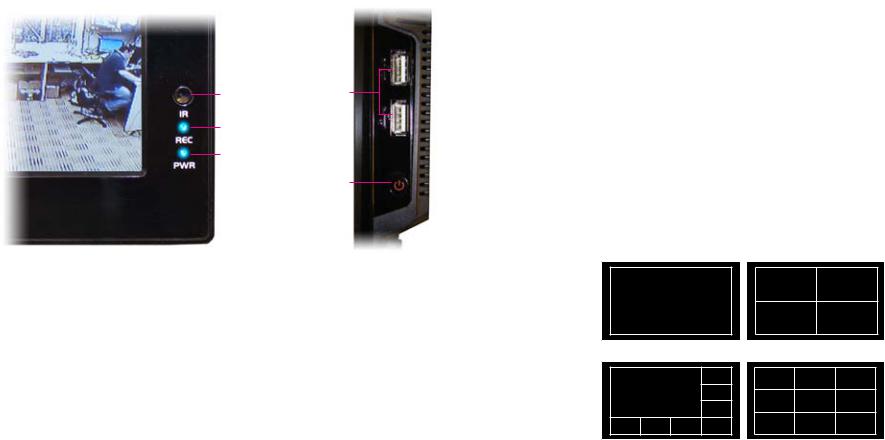
3.3 FRONT AND SIDE PANELS
The front panel of the DVR has minimal features to aid in discretion. The most important item is the Infrared sensor window. This should be kept unobstructed if the remote control is to be used.
The two indicator lights show whether the DVR is currently recording and if it is powered up and operating even if the screen is dark.
The side-mounted USB ports and Power Switch are covered in Section 2.2 but are shown here for ease of reference.
Infrared
Remote
Receiver
Window USB
Ports
Recording
Indicator
Power
Status
Power
Switch
PICTURE 3-4 |
PICTURE 3-5 |
BASIC OPERATION |
CHAPTER 4 |
This chapter is intended to get your system operational in a baseline format now that you’ve connected your system and turned it on. It combines information and instructions on several submenus and settings but may not mention all of the functions or options available in a given menu. For many users, these basic operating instructions may be all they need to operate their security system. But, because this system offers many more features, later chapters will cover those additional operations in greater detail.
4.1 OPERATION |
|
|
|||||
4CHAPTER |
|
||||||
This DVR can be controlled through the USB mouse, the remote control or by using the |
|
||||||
|
|
||||||
buttons on the right side of the device. For the purposes of this manual, instructions will be |
|
|
|||||
given for using the mouse. |
|
|
|||||
In operation, the mouse functions in the same manner as one would use a mouse attached |
BASIC |
||||||
|
|
||||||
to a computer; point, click, right-click, and etcetera. In fields where data needs to be entered, |
OPERATION |
||||||
clicking on the field will bring up a virtual keyboard. (See Section 3.1 Mouse Control) |
|||||||
|
|
||||||
4.2 LIVE VIEW |
|
|
|||||
Live View is the default mode for the DVR. It will display the video feeds from up to 8 cameras |
|
|
|||||
and you do not need to be logged into the DVR to view or change the channel(s) on the |
|
|
|||||
screen. The actual number of channels displayed depends on the number of cameras you |
|
|
|||||
own as well as how many channels your model supports. Channels without a camera will |
|
|
|||||
remain dark with a red “?” icon indicating video loss. You can view a single channel in full- |
|
|
|||||
screen mode or four, eight, nine or 16 channels simultaneously depending on the number of |
|
|
|||||
channels your DVR supports. |
|
|
|||||
|
|
|
|
|
|
|
|
|
|
|
|
|
|
|
|
Single Screen |
4 Screens |
|
|
|
|
|
|
|
|
|
|
|
|
|
|
|
|
8 Screens |
9 Screens |
PICTURE 4-1
Clicking on any one screen in multi-view mode will bring that screen to full-screen single-view mode. The exception is in eight-view where clicking on one of the smaller displays will move it to the larger display.
In addition to selecting the viewing mode from the Shortcut Menu using the mouse, you can also cycle through the modes using the up and down arrows on the remote or the side of the DVR. The left and right arrows on the remote control will cycle through which channels are displayed.
18 |
19 |
In Live View, along with the channel(s), you will see the system date and time displayed along with the name and icons indicating the status of each channel. Setting the system date and time and changing the channel names is covered in Section 5.3 under the Settings menu.
|
|
|
Recording |
|
|
|
Motion detected |
|
|
|
|
|
|
||
|
|
|
|
|
|
|
|
|
|
|
|
|
|
|
|
|
|
|
Video loss |
|
|
|
Camera lock |
|
|
|
|
|
|
||
|
|
|
|
|
|
|
|
|
|
|
|
|
|
|
|
Digital Zoom
When the mouse cursor is in a channel display a white magnifying glass icon will appear in the upper left corner of that image. Clicking on this icon will add a blue check mark to it and you will be able to digitally zoom in on a section of the video feed by clicking and dragging to select the area. Right-click or uncheck the icon to return to normal view. This action can be performed in single or multi-screen viewing modes.
4.3 LOGIN, LOGOUT AND MAIN MENU
LOGIN
When the DVR starts up, the default video display is multiple window mode. Click Enter or click the mouse and the System Login screen will be displayed.
SYSTEM LOGIN
User Name admin 
 Password
  123
123
1 2 3
4 5 6
OK 7 8 Cancel9 0 

PICTURE 4-2
Using the mouse, front panel buttons or remote control, enter your user name and password. Whenever the cursor is over a text field, a keyboard icon will appear to the right. Clicking within the field itself will open the virtual keyboard as explained in Section 3.1. Clicking on the keyboard icon allows you to cycle between numbers, letters (upper and lower case) and symbols when appropriate.
Until new accounts are added, there are three types of pre-configured accounts available to users who log into the DVR:
•Administrator (local and network) Username: admin Password admin
•Local Administrator Username: 888888 Password: 888888
•User (can only monitor, back up and play back video) Username 666666 Password 666666
You must have access rights – whether as the system administrator or logged-in user – in order to change settings. See Account in Section 5.4 for information regarding user accounts.
IMPORTANT! It is highly recommended that you change your system password after you log on for the first time. Record your changes and keep that information stored securely as the system will prevent access if the incorrect login information is attempted three times within a 30-minute period. If you find yourself locked out of the DVR because of this, wait 30 minutes, reboot the DVR and attempt to log into it again.
Once you have logged in, the DVR will display one or more camera channels in Live View. How many channels are displayed will depend on how many cameras you have connected as well as what multi-view mode you have chosen.
After a period of inactivity – configurable in the General Setting submenu described in Section 5.3 – the DVR will log users out. This will require the current user to re-enter their password.
MAIN MENU
After logging in, you can view – and access - the DVR’s functions through the Main Menu.
There are six submenus available; Search,
Info, Setting, Advanced, Backup and
Shutdown. Clicking on an icon will take you to that function or the submenu it represents.
The Main Menu can be accessed at any time from the Live View by right-clicking the mouse and bringing up the Shortcut Menu. Pressing the Return button on the side of the DVR will also bring up the Main Menu.
PICTURE 4-3
SHORTCUT MENU
In Live View mode, right-clicking anywhere on the screen will bring up the Shortcut Menu.
This menu allows you to quickly change your viewing mode as well as moving directly to a selection of menus.
View 1
View 4
View 9
View 16
Pan/Tilt/Zoom
Color Setting
Search
Record
Alarm Output
Alarm Input
Main Menu
PICTURE 4-4
 OPERATION BASIC 4 CHAPTER
20 |
21 |
Loading...