


www.prolink2u.com
PROLiNK® WNR1008
3.75G Wireless-N 4-Port Gigabit Router
User’s Manual
Version 1.00
(English)

FEDERAL COMMUNICATION COMMISSION INTERFERENCE STATEMENT
This equipment has been tested and found to comply with the limits for a Class B digital device, pursuant to Part 15 of the FCC Rules. These limits are designed to provide reasonable protection against harmful interference in a residential installation. This equipment generates uses and can radiate radio frequency energy and, if not installed and used in accordance with the instructions, may cause harmful interference to radio communications.
However, there is no guarantee that interference will not occur in a particular installation. If this equipment does cause harmful interference to radio or television reception, which can be determined by turning the equipment off and on, the user is encouraged to try to correct the interference by one or more of the following measures:
Reorient or relocate the receiving antenna.
Increase the separation between the equipment and receiver.
Connect the equipment into an outlet on a circuit different from that to which the receiver is needed.
Consult the dealer or an experienced radio/TV technician for help.
Warning: Changes or modifications to this unit not expressly approved by the party responsible for compliance could void the user authority to operate the equipment.
This device complies with Part 15 of the FCC Rules. Operation is subject to the following two conditions: (1) this device may not cause harmful interference, and (2) this device must accept any interference received, including interference that may cause undesired operation.
The user’s manual or instruction manual for an intentional or unintentional radiator shall caution the user that changes or modifications not expressly approved by the party responsible for compliance could void the user’s authority to operate the equipment.
CAUTION:
1.To comply with FCC RF exposure compliance requirements, a separation distance of at least 20 cm must be maintained between the antenna of this device and all persons.
2.This Transmitter must not be co-located or operating in conjunction with any other antenna or transmitter

TABLE OF CONTENT
CHAPTER 1: INTRODUCTION.......................................................................................................................... |
1 |
|
1.1. |
Features ..................................................................................................................................................................................................................... |
1 |
1.2. |
Physical Details ....................................................................................................................................................................................................... |
1 |
CHAPTER 2: ABOUT OPERATION MODES ..................................................................................................... |
3 |
|
2.1. |
Operation Modes .................................................................................................................................................................................................. |
3 |
2.2. |
Router Mode ........................................................................................................................................................................................................... |
3 |
2.3. |
Access Point Mode ............................................................................................................................................................................................... |
4 |
2.4. |
Converter Mode..................................................................................................................................................................................................... |
4 |
CHAPTER 3: CONFIGURATION........................................................................................................................ |
5 |
|
3.1. |
Hardware Connection.......................................................................................................................................................................................... |
5 |
3.2. |
Login ........................................................................................................................................................................................................................... |
5 |
3.3. |
Status .......................................................................................................................................................................................................................... |
7 |
3.4. |
Network ..................................................................................................................................................................................................................... |
8 |
3.5. |
Wireless................................................................................................................................................................................................................... |
15 |
3.6. |
Firewall .................................................................................................................................................................................................................... |
24 |
3.7. |
Administration ..................................................................................................................................................................................................... |
29 |
CHAPTER 4: PC CONFIGURATION ................................................................................................................ |
35 |
|
4.1. |
Overview................................................................................................................................................................................................................. |
35 |
4.2. |
Windows Clients.................................................................................................................................................................................................. |
35 |
4.3. |
Macintosh Clients ............................................................................................................................................................................................... |
40 |
4.4. |
Linux Clients.......................................................................................................................................................................................................... |
41 |
4.5. |
Other Unix Systems ........................................................................................................................................................................................... |
41 |
4.6. |
Wireless Station Configuration..................................................................................................................................................................... |
41 |
CHAPTER 5: TROUBLESHOOTING................................................................................................................. |
43 |
|
5.1. |
Overview................................................................................................................................................................................................................. |
43 |
5.2. |
General Problems ............................................................................................................................................................................................... |
43 |
5.3. |
Internet Access .................................................................................................................................................................................................... |
43 |
5.4. |
Wireless Access ................................................................................................................................................................................................... |
44 |
CHAPTER 6: ABOUT WIRELESS LANS........................................................................................................... |
45 |
|
6.1. BSS (Basic Service Set)...................................................................................................................................................................................... |
45 |
|
6.2. |
Channels................................................................................................................................................................................................................. |
45 |
6.3. |
Security ................................................................................................................................................................................................................... |
45 |
6.4. |
Wireless LAN Configuration........................................................................................................................................................................... |
46 |
CHAPTER 7: TECHNICAL SUPPORT .............................................................................................................. |
47 |
|
7.1. FREE TECHNICAL SUPPORT HOTLINE........................................................................................................................................................ |
47 |
|
7.2. |
WALK-IN SUPPORT............................................................................................................................................................................................ |
47 |
7.3. |
ONLINE TECHNICAL SUPPORT..................................................................................................................................................................... |
47 |
PROLiNK® WNR1008 |
www.prolink2u.com |
|
|
CHAPTER 1: INTRODUCTION
The PROLiNK® WNR1008 3.75G Wireless-N 4-Port Gigabit Router supports 4 ports 10/100/1000M Ethernet for LAN and 1 port 10/100/1000M Ethernet interface for WAN. With the advanced MIMO technology, it can support the data transmission rate 6 times more (up to 300 Mbps) and the coverage 3 times more than IEEE 802.11b/g devices. The Wireless Router enables your whole network sharing a high-speed cable or DSL Internet connection. With it, you can share a high-speed Internet connection, files, printers, and multi-player games at incredible speeds, without the hassle of stringing wires. It also offers easy configuration for your wireless network at home and presents wireless network of high functionality, security, and flexibility.
1.1.
Support 4 ports 10/100/1000M Ethernet for LAN and 1 port 10/100/1000M Ethernet interface for WAN.
Clock rate up to 600MHz.
Support the IEEE 802.11n/b/g standard, high speed data rate up to 300Mbps, two transmit and two receive path (2T2R)
High security with build-in Security: WEP 64/128, WPA, WPA2, 802.1x and 802.11i.
Supports 1 additional USB port.
Supports WPS (Wi-Fi Protected Setup) with physical push button.
High security with build-in Security: WEP 64/128, WPA, WPA2, 802.1x and 802.11i.
Support Client, AP, WDS, AP+WDS mode.
Advanced Quality of Service (QoS), WMM.
Easy web browser configuration for home user setup.
Support USB Network attached storage (NAS) and media share function.
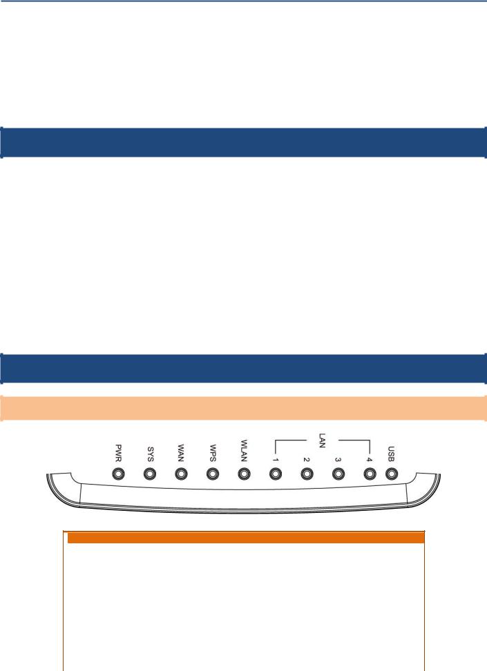
1.2.
Top LEDs (Top view)
 LED Behavior
|
LED |
|
|
Printed |
|
|
Color |
|
|
Behavior |
|
|
Indication |
|
|
|
|
|
|
|
|
|
|
|
|||||
|
Power |
|
|
PWR |
|
|
Green |
|
|
ON |
|
|
Power on |
|
|
|
|
|
|
|
|
|
|||||||
|
|
|
|
|
|
|
OFF |
|
|
Power off |
|
|||
|
|
|
|
|
|
|
|
|
|
|||||
|
|
|
|
|
|
|
|
|
|
|
|
|
||
|
|
|
|
|
|
|
|
|
|
|
||||
|
|
|
|
|
|
|
|
|
|
ON |
|
System is ready to login web server |
||
|
|
|
|
|
|
|
|
|
|
|||||
|
System |
|
SYS |
|
Green |
|
OFF |
|
System is not ready to login web server |
|||||
|
|
|
|
|
|
|
|
|
|
|
|
|
||
|
|
|
|
|
|
|
|
|
|
Blinking |
|
System is set to factory default |
||
|
|
|
|
|
|
|
|
|
|
|
|
|
||
|
|
|
|
|
|
|
|
|
|
ON |
|
|
Internet link / active |
|
|
Internet |
|
|
WAN |
|
|
Green |
|
|
OFF |
|
|
Internet function off |
|
|
|
|
|
|
|
|
|
|
|
|||||
|
|
|
|
|
|
|
|
|
|
|
|
|
||
|
|
|
|
|
|
|
|
|
|
Blinking |
|
|
Internet traffic transmitting |
|
|
|
|
|
|
|
|
|
|
|
|
|
|
|
|
Version 1.00 |
1 |
English |
PROLiNK® WNR1008 |
|
|
|
|
|
|
|
|
|
|
www.prolink2u.com |
|||||
|
|
|
|
|
|
|
|
|
|
|
|
|
|
|
|
|
|
|
|
|
|
|
|
|
|
|
|
|
|
|
|
|
|
|
|
|
|
|
|
|
|
|
|
|
ON |
|
WPS setup successfully |
|
||
|
|
|
|
|
|
|
|
|
|
|
|
|
|
|
|
|
|
|
WPS |
|
WPS |
|
Green |
|
OFF |
|
WPS is disabled |
|
|||||
|
|
|
|
|
|
|
|
|
|
|
|
|
|
|
|
|
|
|
|
|
|
|
|
|
|
|
|
Blinking |
|
WPS is enabled to make a connection |
|
||
|
|
|
|
|
|
|
|
|
|
|
|
|
|
|
|
|
|
|
|
|
|
|
|
|
|
|
|
OFF |
|
|
WLAN off |
|
|
|
|
Wireless LAN |
|
|
WLAN |
|
|
Green |
|
|
ON |
|
|
WLAN link / active |
|
|
|
|
|
|
|
|
|
|
|
|
|
|
|||||
|
|
|
|
|
|
|
|
|
|
|
Blinking |
|
|
WLAN traffic transmitting |
|
|
|
|
|
|
|
|
|
|
|
|
|
OFF |
|
LAN function off |
|
||
|
|
|
|
|
|
|
|
|
|
|
|
|
||||
|
|
LAN |
|
|
|
|
Green |
|
ON |
|
LAN link / active |
|
||||
|
|
|
|
|
|
|
|
|
|
|
|
|
|
|
||
|
|
|
|
|
|
|
|
|
|
|
Blinking |
|
LAN traffic transmitting |
|
||
|
|
|
|
|
|
|
|
|
|
|
|
|
|
|
||
|
|
USB |
|
|
WPS |
|
|
Green |
|
|
ON |
|
|
USB is connected |
|
|
|
|
|
|
|
|
|
|
|
||||||||
|
|
|
|
|
|
|
|
OFF |
|
|
USB is disconnected |
|
|
|||
|
|
|
|
|
|
|
|
|
|
|
|
|
|
|
||
|
|
|
|
|
|
|
|
|
|
|
|
|
|
|
|
|
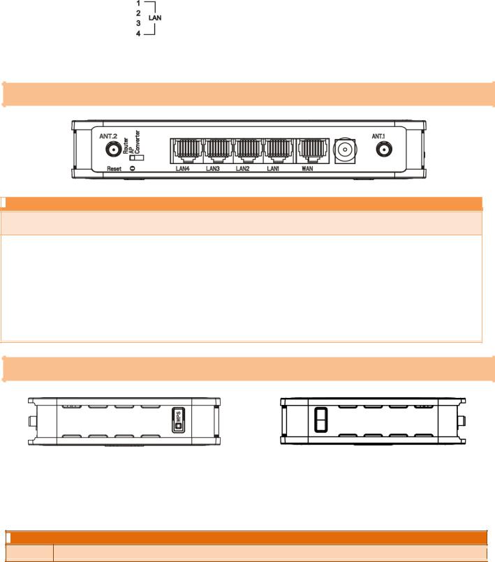
Ports and Buttons (Rear view)
 Ports and buttons
Ant. 1 |
Install the appending antennas here. |
|
Ant. 2 |
||
|
Press 2 seconds, the LED will be off.
|
Reset |
|
Keep on pressing reset button 2~5 seconds, the system will reboot automatically. |
|||
|
|
Keep on pressing the reset button more than 5 seconds, the Wireless Router will set all setting back to factory |
||||
|
|
|
||||
|
|
|
|
|
default. |
|
|
|
|
|
|
|
|
|
LAN 1-4 |
|
|
Use standard LAN cables (RJ45 connectors) to connect your PCs to this port. If required, any port can be connected to |
|
|
|
|
|
another hub. Any LAN port will automatically function as an "Uplink" port when necessary. |
|
||
|
|
|
|
|
||
|
WAN |
Connect the ADSL or Cable Modem here with RJ45 cable. If your modem came with a cable, use the supplied cable, |
||||
|
otherwise, use a standard LAN cable (RJ45 connectors). |
|||||
|
|
|
||||
|
|
|
||||
|
DC 12V |
|
|
Connect the supplied power adapter here. |
|
|
Side Panel (Side view)
|
|
|
|
(Left sideview) |
(Right sideview) |
|
|
|
|
|
|
|
Left-sideview |
|
|
||
|
WPS |
|
|
To enable the WPS function press the physical WPS button on the Wireless Router once, then the LED will start to flash. |
|
|
|
|
Please make a connection with other WPS supported device within 2 minutes. |
|
|
|
|
|
|
|
|
|
|
|
|
|
|
 Right-sideview
USB |
Insert the USB 3.5G card that provided by your ISP (Internet Service Provider) or USB network attached storage here. |
Version 1.00 |
2 |
English |
PROLiNK® WNR1008 |
www.prolink2u.com |
|
|
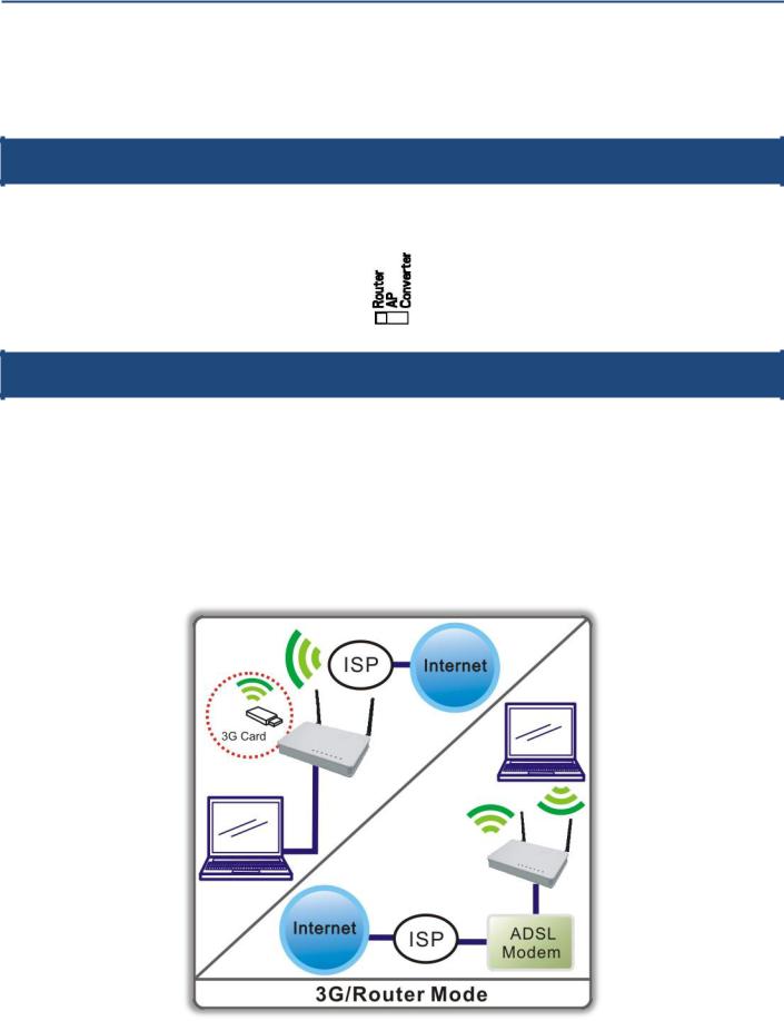
CHAPTER 2: ABOUT OPERATION MODES
This device provides operational applications with Router, AP and Converter modes, which are mutually exclusive. This device is shipped with configuration that is functional right out of the box. If you want to change the settings in order to perform more advanced configuration or even change the mode of operation, you can MANUALLY switch to the mode you desired by the manufacturer as described in the following sections.
2.1.
You have to MANUALLY switch the bar into the mode you preferred, Router, AP or Converter modes, then the device will reboot automatically into the mode you have selected.
2.2.
In this mode, the device is supposed to connect to internet via ADSL/Cable Modem. The NAT is enabled and PCs in LAN ports share the same IP address to ISP (Internet Service Provider) through WAN port. The connection type can be setup in PPPoE, DHCP client, PPTP client, L2TP client or static IP.
The wireless connection will be set up from a point-to-point LAN into a point-to-multipoint WAN. This device connects all the stations (PC or notebook with wireless function) to a wireless network. All stations can have the Internet access if only the device has the Internet connection.
Version 1.00 |
3 |
English |
PROLiNK® WNR1008 |
www.prolink2u.com |
|
|
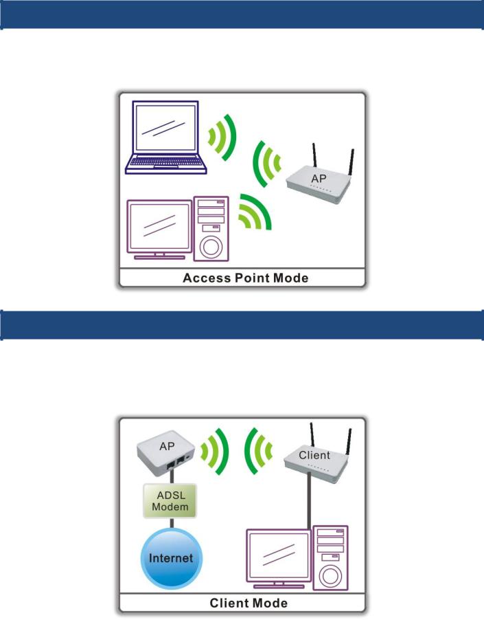
2.3.
When acting as an Access Point (AP), this device connects all the stations (PC/notebook with wireless network adapter) to a wireless network. All stations can have the Internet access if only the Access Point has the Internet connection.
2.4.
If set to Converter mode, a device connects to each other through an access point or a base station (gateway or router.)
This device can work like a wireless station when it’s connected to a computer directly, so that the computer can send packets from wired end to wireless interface.
Version 1.00 |
4 |
English |
PROLiNK® WNR1008 |
www.prolink2u.com |
|
|
CHAPTER 3: CONFIGURATION
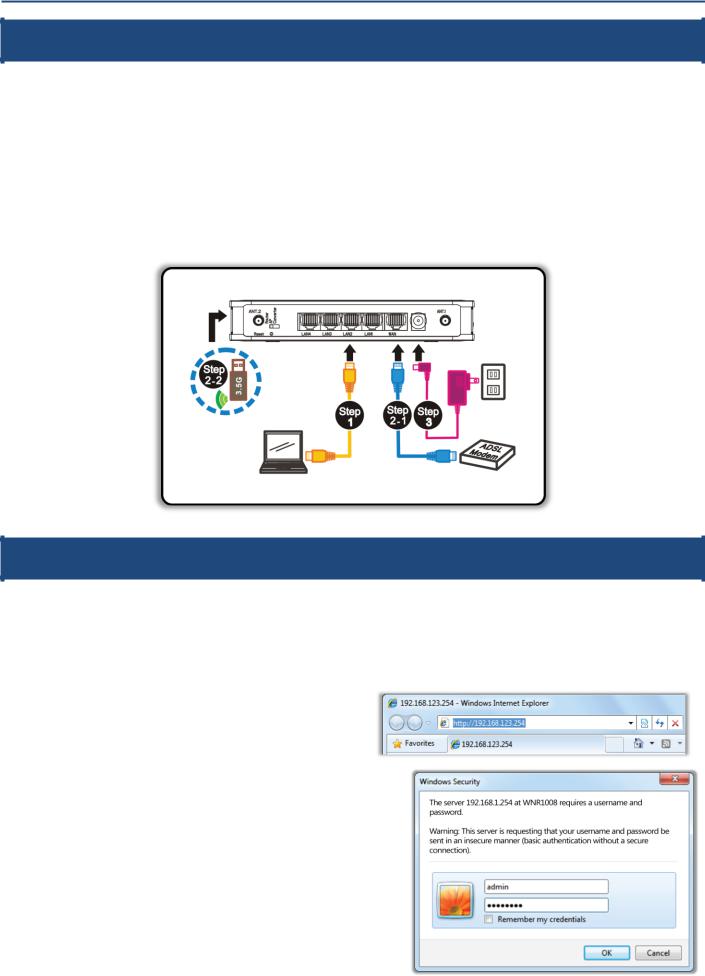
3.1.
Step 1. Connect one end of the Ethernet cable to the LAN port (1~4) of the Wireless Router, another end to your PC or notebook.
Step 2. There are two connection methods to connect to Internet (Only one can be used):
2-1. Connect Ethernet cable one end to the WAN (Internet) port of the Wireless Router, the other end to the ADSL or cable modem.
2-2. Or you can insert 3.5G USB card (that provide by your ISP) into USB port.
Step 3. Finally, connect the Wireless Router with a power to an outlet.
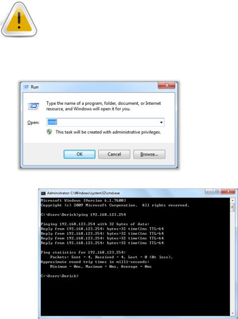
3.2.
1.Start your computer and make sure the connection by an Ethernet cable between your computer and the Wireless Router.
2.Start your Web Browser.
3.In the Address box, enter the IP address of the Wireless Router, as in this example, which uses the Wireless Router's default IP address: http://192.168.123.254
4.After connected successfully, the following screen will show up. Simply enter the username "admin" and password "password" to login.
Version 1.00 |
5 |
English |
PROLiNK® WNR1008 |
www.prolink2u.com |
|
|
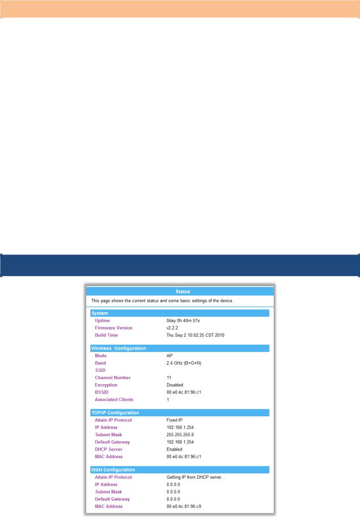
Refer to below troubleshooting,
If you encounter difficulty for connecting the WNR1008
If the WNR1008 does not respond
The Wireless Router is properly installed, LAN connection is OK, and it is powered ON. You can test the connection by using the "Ping" command:
Please go to Start>Run…> Enter “cmd” command in the column to open the MS-DOS window.
Enter the command: ping 192.168.123.254
If no response is received, either the connection is not working, or your PC's IP address is not compatible with the Wireless Router's IP Address. (See next item.)
If your PC is using a fixed IP Address, its IP Address must be within the range 192.168.123.1 to 192.168.123.253 to be compatible with the Wireless Router's default IP Address of 192.168.123.253. Also, the Network Mask must be set to 255.255.255.0. See Chapter 4 - PC Configuration for details on checking your PC's TCP/IP settings.
Ensure that your PC and the Wireless Router are on the same network segment. (If you don't have a router, this must be the case.)
Ensure you are using the wired LAN interface. The Wireless interface can only be used if its configuration matches your PC's wireless settings.
Version 1.00 |
6 |
English |
PROLiNK® WNR1008 |
www.prolink2u.com |
|
|
Common Connection Types
The Internet connection type is according to the ISP (Internet Service Provider) that you selected or subscribed.
|
Modem Type |
|
|
IP Type |
|
|
Details |
|
|
ISP Data required |
|
|
|
|
|
|
|
|
|
|
|
Usually, none. |
|
|
|
|
|
|
|
|
Your IP address is allocated automatically, when you |
|
|
However, some ISP's may |
|
|
|
|
|
Dynamic IP address |
|
|
|
|
require you to use a particular |
|
|
|
|
|
|
|
|
|
|
|
|||
|
|
|
|
|
|
connect to you ISP. |
|
|
|
||
|
|
|
|
|
|
|
|
|
Hostname, Domain name, or |
|
|
|
|
|
|
|
|
|
|
|
|
||
|
|
|
|
|
|
|
|
|
|
|
|
|
|
|
|
|
|
|
|
|
|
MAC (physical) address. |
|
|
Cable Modem |
|
|
|
|
|
|
|
|
|
|
|
|
|
|
|
|
|
|
|
|
|
|
|
|
|
|
|
|
|
|
|
IP address allocated to you. |
|
|
|
|
|
|
|
|
|
|
|
|
|
|
|
|
|
|
|
|
|
|
|
|
|
|
|
|
|
|
|
|
|
|
|
|
Some ISP's may also require you |
|
|
|
|
|
|
|
|
|
|
|
|
|
|
|
|
|
Static (Fixed) IP address |
|
|
Your ISP allocates a permanent IP address to you. |
|
|
to use a particular Hostname, |
|
|
|
|
|
|
|
|
|
|
|
Domain name, or MAC |
|
|
|
|
|
|
|
|
|
|
|
|
|
|
|
|
|
|
|
|
|
|
|
(physical) address. |
|
|
|
|
|
|
|
|
|
|
|
|
|
|
|
|
|
Dynamic IP address |
|
|
Your IP address is allocated automatically, when you |
|
|
None. |
|
|
|
|
|
|
|
|
|
|
|||
|
|
|
|
|
|
connect to you ISP. |
|
|
|
||
|
|
|
|
|
|
|
|
|
|
|
|
|
|
|
|
|
|
|
|
|
|
|
|
|
DSL Modem |
|
|
Static (Fixed) IP address |
|
|
Your ISP allocates a permanent IP address to you. |
|
|
IP address allocated to you. |
|
|
|
|
|
|
|
|
|
||||
|
|
|
|
|
|
|
|
||||
|
|
|
|
PPPoE |
|
|
You connect to the ISP only when required. The IP |
|
|
User name and password. |
|
|
|
|
|
|
|
|
|
|
|||
|
|
|
|
|
|
address is usually allocated automatically. |
|
|
|
||
|
|
|
|
|
|
|
|
|
|
|
|
|
|
|
|
|
|
|
|
|
|
|
|
|
|
|
|
|
|
|
|
|
|
|
|
|
|
|
|
|
|
|
|
|
|
The ISP's may require you to |
|
|
Other |
|
|
Dynamic IP address |
|
|
Your IP address is allocated automatically, when you |
|
|
use a particular Hostname, |
|
|
|
|
|
|
|
|
|
||||
|
|
|
|
|
|
|
|
||||
|
(eg: 3.5G Wireless Card) |
|
|
|
|
connect to you ISP. |
|
|
Domain name, or MAC |
|
|
|
|
|
|
|
|
|
|
|
|||
|
|
|
|
|
|
|
|
|
|||
|
|
|
|
|
|
|
|
|
|||
|
|
|
|
|
|
|
|
|
|
(physical) address. |
|
|
|
|
|
|
|
|
|
|
|
|
|
|
|
|
|
|
|
|
|
|
|
|
|
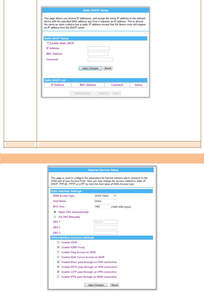
3.3.
PROLiNK_WNR1008
Version 1.00 |
7 |
English |
PROLiNK® WNR1008 |
www.prolink2u.com |
|
|
3.4.
LAN Interface Setup
192.168.123.100
255.255.255.0
192.168.123.254
192.168.123.100 192.168.123.200
|
Item / Function |
|
Descriptions / Instructions |
|
|||||||
|
|
|
|
|
|
|
|
|
|
|
|
|
IP Address |
|
|
Shows the IP address of the Wireless Router (Default IP address is 192.168.123.254) |
|
||||||
|
Subnet Mask |
|
The subnet mask of the Wireless Router (Default subnet mask is 255.255.255.0.) |
|
|||||||
|
|
|
|
|
|
|
|
|
|
|
|
|
Default Gateway |
|
|
Shows the default gateway of this Wireless Router. |
|
||||||
|
|
|
|
Disable: Select to disable this Wireless Router to distribute IP addresses to connected clients. |
|
||||||
|
DHCP Mode |
|
Server: Select to enable this Wireless Router to distribute IP addresses (DHCP Server) to connected clients. And the |
|
|||||||
|
|
following field will be activated for you to enter the starting IP address. |
|
||||||||
|
|
|
|
|
|||||||
|
|
|
|
Client: Select the client mode to use the |
|
||||||
|
|
|
|
|
|
|
|
|
|
|
|
|
|
|
|
The starting address of this local IP network address pool. The pool is a piece of continuous IP address segment, the |
|
||||||
|
|
|
|
device will distribute IP addresses from 192.168.123.100 to 192.168.123.200 to all the computers in the network that |
|
||||||
|
|
|
|
request IP addresses from DHCP server (Router). The end IP address maximum is 253. |
|
||||||
|
|
|
|
Note: If “Continuous IP address pool starts” is set at 192.168.123.1 and the “Number of IP address in pool end” is |
|
||||||
|
|
|
|
253, the device will distribute IP addresses from 192.168.123.100 to 192.168.123.253 to all the computers in the |
|
||||||
|
|
|
|
network that request IP addresses from DHCP server (Router). |
|
||||||
|
|
|
|
|
|
|
|
|
|
|
|
|
|
|
|
Click |
Show Client |
button to show Active DHCP Client Table. The table shows assigned IP address, MAC address |
|
||||
|
|
|
|
and time expired for each client. |
|
||||||
|
DHCP Client Range |
|
|
|
|
|
|
|
|
|
|
|
|
|
|
|
|
|
|
|
|
|
|
|
|
|
|
|
|
|
|
|
|||
|
|
|
|
|
192.168.123.100 |
|
|
|
|
||
|
|
|
|
Refresh: Click this button to refresh the table. |
|
||||||
|
|
|
|
Close: Click this button to close the window. |
|
||||||
|
Static DHCP |
|
Check the box to enable the Static DHCP function, default setting is disabled. When set to enabled, user can click |
Set |
|
|
|||||
Version 1.00 |
8 |
English |
PROLiNK® WNR1008 |
|
www.prolink2u.com |
||
|
|
|
|
|
|
|
|
|
|
|
|
Static DHCP |
button to set the Static DHCP function. |
|
IP Address: Enter the fixed IP address that DHCP Server assigned to a certain connected station.
MAC Address: Enter the MAC address of a certain station, and then the DHCP Server will to distribute a fixed IP address to the station automatically once they connected.
Comment: You can enter a comment to description above IP address or MAC address.
Apply Changes: After completing the settings on this page, click Apply changes button to save the settings. Reset: Click Reset to restore to default values.
Static DHCP List: Here shows the static IP addresses that have been assigned according to the MAC address. Delete Selected: Click Delete Selected to delete items which are selected.
Delete All: Click Delete All button to delete all the items. Reset: Click Reset button to rest.
 Clone MAC Address
 This table displays you the station MAC information.
Internet Service Setup
Version 1.00 |
9 |
English |
PROLiNK® WNR1008 |
|
|
www.prolink2u.com |
|||
|
|
|
|
|
|
|
|
|
|
|
|
|
|
|
Item / Function |
|
Descriptions / Instructions |
|||
|
|
|
|
|
|
|
|
WAN Access Type |
|
Select the WAN Access Type Static IP, DHCP Client, PPPoE, or Mobile Networks from the pull-down list. Default |
|
|
|
|
|
|
|
|||
|
|
|
setting is DHCP (Auto Config) enabled. |
|
||
|
|
|
|
|
|
|
|
|
|
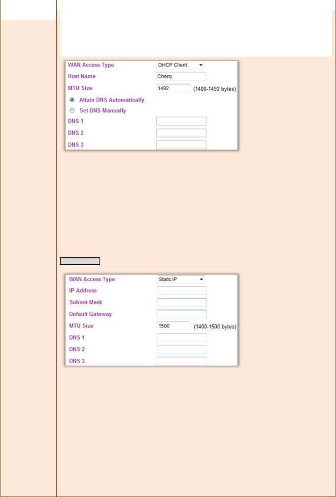
DHCP Client |
|
|
|
|
|
|
|
|
|
|
If the DHCP Client be selected, the computer will obtain the IP address automatically.
Hostname: Enter the hostname that assigned IP address to your computer in this field. Maximum input is 32 alphanumeric characters (case sensitive).
MTU Size: The most appropriate MTU (Maximum Transmission Unit) namely the maximum packet size, the default value is 1492 for your application. Reducing the packet size can help connecting to certain web sites or speeding up packet transfer rate. If the incorrect packet size is entered, you may not be able to open certain web sites.
Select to Attain DNS Automatically or select Set DNS Manually to set the DNS server IP address at the following DNS 1~3 columns. Default setting is Attain DNS Automatically.
DNS 1: Enter the DNS server IP address (es) provided by your ISP, or you can specify your own preferred DNS server IP address (es).
DNS 2~3: This servers are optional. You can enter another DNS server’s IP address as a backup. DNS 2 and 3 servers will be used when the DNS 1 server fails.
Static (Fixed IP)
If the Static IP be selected, user have to set up the IP address, subnet mask and default gateway according to the ISP (Internet Service Provider) that provide the related information.
IP Address: Enter the WAN IP address provided by your ISP here.
Subnet Mask: Enter the subnet mask here.
Default Gateway: Enter the default gateway IP address provided by your ISP here.
MTU Size: The most appropriate MTU (Maximum Transmission Unit) namely the maximum packet size, the default value is 1492 for your application. Reducing the packet size can help connecting to certain web sites or speeding up packet transfer rate. If the incorrect packet size is entered, you may not be able to open certain web sites.
Select to Attain DNS Automatically or select Set DNS Manually to set the DNS server IP address at the following DNS 1~3 columns. Default setting is Attain DNS Automatically.
DNS 1: Enter the DNS server IP address (es) provided by your ISP, or you can specify your own preferred DNS server IP address (es).
DNS 2~3: This servers are optional. You can enter another DNS server’s IP address as a backup. DNS 2 and 3 servers
Version 1.00 |
10 |
English |
PROLiNK® WNR1008 |
www.prolink2u.com |
|
|
will be used when the DNS 1 server fails.
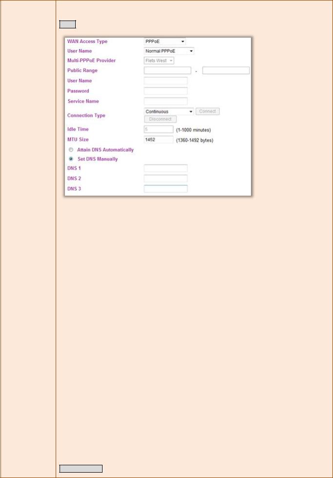
PPPoE
If the PPPoE be selected, user have to set up the user name and password according to the ISP (Internet Service
Provider) that provided the related information.
PPPoE Type: Select the PPPoE types, Normal PPPoE, Multiple PPPoE and Unnumbered PPPoE form the pull-down menu.
Multi-PPPoE provider: If user select Multiple PPPoE type, user have to setup the PPPoE provider here. Select Flets West, Next West, Flets East, and Flets Next from the pull-down menu.
Public Range: If user selected Unnumbered PPPoE type, have to setup the range here.
User Name: Enter the username that provide by your ISP (Internet Service Provider). Maximum input is 32 alphanumeric characters (case sensitive).
Password: Enter the password that provide by your ISP. Maximum input is 32 alphanumeric characters (casesensitive).
Service Name: Enter the Internet service provider’s name here.
Connection Type: Select the connection type Continuous, Connect on Demand or Manual from the pull-down menu. If selected Manual user can click Connect button to make a connection.
Idle Time: It represents that the device will idle after the minutes you set. The time must be set between 1~1000 minutes. Default value of idle time is 5 minutes. This function will be available when the Connection Type is selected to Connect on Demand.
MTU Size: MTU (Maximum Transmission Unit, namely the maximum packet size) for your application. Reducing the packet size can help connecting to certain web sites or speeding up packet transfer rate. If the incorrect selection is entered, you may not be able to open certain web sites.
Connection Type: Select the connection type Continuous, Connect on Demand or Manual from the pull-down menu. If selected Manual user can click Connect button to make a connection.
Idle Time: It represents that the device will idle after the minutes you set. The time must be set between 1~1000 minutes. Default value of idle time is 5 minutes. This function will be available when the Connection Type is selected to Connect on Demand.
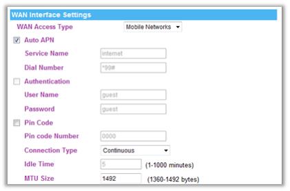
Mobile Networks
Version 1.00 |
11 |
English |
PROLiNK® WNR1008 |
www.prolink2u.com |
|
|
|
User have to insert USB card that provide by Internet service provider into the USB port of the wireless router |
|
first, therefore, the Mobile networks function can be used. |
|
Auto APN: APN (Access Point Name.) If this function be selected, the system will auto detect the mobile network |
|
setting via the USB that provide by the Internet service provider (ISP). To use the default settings is recommend. |
|
Service Name: Keep the default setting or enter the service name that ISP provided. |
|
Dial Number: Keep the default setting or enter the dial number that ISP provided. |
|
Authentication: Check the box to enable to authentication function. |
|
User Name: Enter the user name that provide by your ISP. |
|
Password: Enter the password that provide by your ISP. |
|
Pin code: Keep the default setting or enter the SIM card Pin code that ISP provided. |
|
Connection Type: Select the connection type Continuous, Connect on Demand from the pull-down menu. |
|
Idle Time: It represents that the device will idle after the minutes you set. The time must be set between 1~1000 |
|
minutes. Default value of idle time is 5 minutes. This function will be available when the Connection Type is selected |
|
to Connect on Demand. |
|
MTU Size: MTU (Maximum Transmission Unit, namely the maximum packet size) for your application. Reducing the |
|
packet size can help connecting to certain web sites or speeding up packet transfer rate. If the incorrect selection is |
|
entered, you may not be able to open certain web sites. |
|
|
Enable uPNP… |
Check to enable the listed functions. |
|
|
Apply |
After completing the settings on this page, click Apply button to save the settings. |
|
|
|
|
Cancel |
Click Cancel to restore to default values. |
|
|
Version 1.00 |
12 |
English |
PROLiNK® WNR1008 |
www.prolink2u.com |
|
|
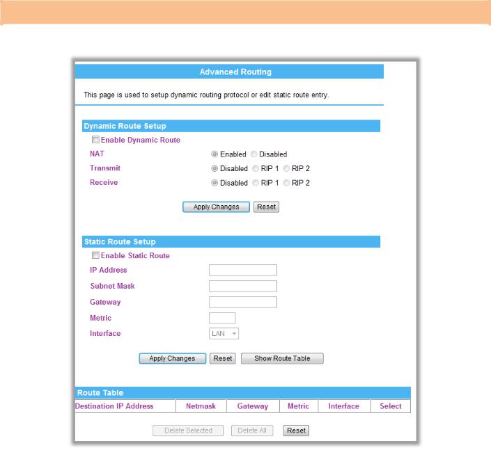
Advanced Routing
If you connect several routers with this Wireless Router, you may need to set up a predefined routing rule to have more effective network topology/traffic, this is called static route between those routers and the Wireless Router.
Item / Function |
|
Descriptions / Instructions |
|
|
|
|
|
Enable Dynamic |
|
Check to enable the dynamic route function. |
|
Route |
|
NAT: Select to enable the network address translation function. |
|
|
|
Transmit: Select to use the Routing Information Protocol, the function will select the packet transmitting route that |
|
|
|
|
|
|
|
pass through least routers. |
|
|
|
Receive: Select to use the Routing Information Protocol, the function will select the packet receiving route that pass |
|
|
|
through least routers. |
|
Enable Static Route |
|
IP address: Enter the Gateway IP address in the field. |
|
|
|
Subnet Mask: Enter the Gateway subnet mask here. |
|
|
|
Gateway: Enter the gateway name or domain name here. |
|
|
|
Metric: The route with the lowest metric is the preferred route. |
|
|
|
Interface: Select to use LAN or WAN as the physical interface from where the packets will be sent. |
|
|
|
|
|
Destination |
|
The network address of the destination LAN segment. When a packet with destination IP address that matches to this |
|
|
|
field, it will route to the device set in the Route Gateway field. |
|
|
|
|
|
Range |
|
Select Host or Net from the pull-down menu. If select Net, please enter the Netmask in the following column. |
|
|
|
|
|
IP address |
|
Enter the Gateway IP address in the field. |
|
Interface |
|
You can |
|
|
|
|
|
Comment |
|
Enter note or remark here. |
|
Apply |
|
After completing the settings on this page, click Apply button to save the settings. |
|
|
|
|
|
Reset |
|
Click to discard current setting. |
|
|
|
|
|
Version 1.00 |
13 |
English |
PROLiNK® WNR1008 |
www.prolink2u.com |
|
|
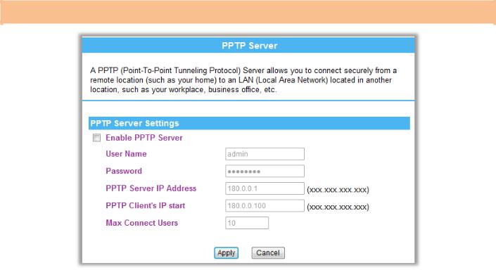
PPTP Server
|
Item / Function |
|
|
Descriptions / Instructions |
|
|
|
|
|
|
|
|
Enable PPTP Server |
|
|
Check to enable the PPTP server function, this function allows you to connect securely from a remote location (such |
|
|
|
|
|
as your home) to an LAN (Local Area Network) located in another location, such as your workplace, business office |
|
|
|
|
|
||
|
|
|
|
and so on. |
|
|
User Name |
|
|
Enter username in the column, when the PPTP client try to connect to the PPTP sever should login with the username. |
|
|
|
|
|
|
|
|
Password |
|
|
Setup the password in the column, when the PPTP client try to connect to the PPTP sever should login with the |
|
|
|
|
|
password. |
|
|
|
|
|
|
|
|
|
|
|
|
|
|
PPTP Server IP |
|
|
Setup the PPTP server IP address here. |
|
|
address |
|
|
|
|
|
|
|
|
|
|
|
|
|
|
|
|
|
PPTP Client’s IP Start |
|
|
Setup the Client’s start IP address here. |
|
|
|
|
|
|
|
|
Max Connect Users |
|
|
Setup the PPTP client allowed maximum here. |
|
|
|
|
|
|
|
Version 1.00 |
14 |
English |
PROLiNK® WNR1008 |
www.prolink2u.com |
|
|
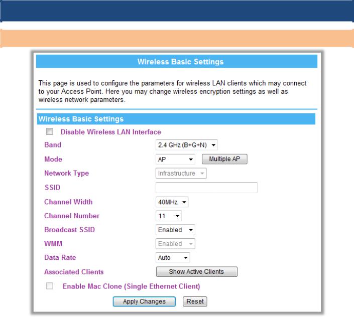
3.5.
Basic
PROLiNK_WNR1008
Item / Function |
|
Descriptions / Instructions |
|
|
|
|
|
|
|
Disable Wireless |
|
Check to disable the wireless function. If the wireless LAN interface be disabled, the WLAN LED on the front LED will |
|
|
LAN Interface |
|
be off. |
|
|
Band |
|
You can choose one mode of the following you need. |
|
|
|
|
2.4GHz (B): 802.11b supported rate only. |
|
|
|
|
2.4GHz (G): 802.11g supported rate only. |
|
|
|
|
2.4GHz (N): 802.11n supported rate only. |
|
|
|
|
2.4GHz (B+G): 802.11b supported rate and 802.11g supported rate. |
|
|
|
|
2.4GHz (G+N): 802.11g supported rate and 802.11n supported rate. |
|
|
|
|
2.4GHz (B+G+N): 802.11b, 802.11g and 802.11n supported rate. |
|
|
|
|
The default is 2.4GHz (B+G+N) mode. |
|
|
|
|
|
|
|
Mode |
|
Under Router operation mode, user can select AP, WDS, and AP+WDS from the pull-down list. For AP mode, user can |
|
|
|
|
select AP, Client, WDS and AP+WDS mode. Under client mode, there is only Client mode can be selected. |
|
|
|
|
|
||
|
|
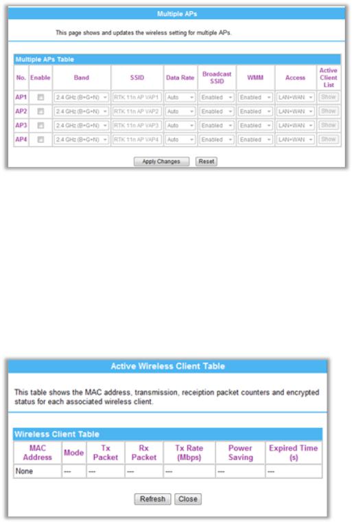
Multiple APs |
|
|
|
|
This page shows and updates the wireless setting for multiple APs. |
|
|
|
|
|
|
|
Version 1.00 |
15 |
English |
PROLiNK® WNR1008 |
|
|
|
www.prolink2u.com |
|||||
|
|
|
|
|
|
|
|
|
|
|
|
|
|
|
|
|
|
|
|
|
|
|
|
|
|
|
|
|
|
|
|
|
|
|
User can set up the multiple AP here. |
|
|
||
|
|
Network Type |
|
If the mode be set to AP or Client mode that the network type can be set to Infrastructure or Ad hoc. |
|
||||
|
|
|
|
|
|
|
|
|
|
|
|
SSID |
|
|
A SSID (Service Set Identifier) is referred to a network name because essentially it is a name that identifies a wireless |
|
|
||
|
|
|
|
||||||
|
|
|
|
network (case-sensitive). |
|
|
|||
|
|
|
|
|
|
|
|||
|
|
|
|
|
|||||
|
|
Channel Width |
|
Select 20MHz/40MHz channel width, the channel number will be form 5~11 and auto; Select 20MHz channel width |
|
||||
|
|
|
|
|
the channel number will be form 1~11 and auto. Default is 20MHz/40MHz. |
|
|||
|
|
|
|
|
|
|
|
||
|
|
Channel Selection |
|
|
The channel number base on the channel width you select. |
|
|
||
|
|
Broadcast SSID |
|
Enabled: This wireless AP will broadcast its SSID to stations. |
|
||||
|
|
|
|
|
Disabled: This wireless AP will not broadcast its SSID to stations. If stations want to connect to this wireless AP, this |
|
|||
|
|
|
|
|
AP’s SSID should be known in advance to make a connection. |
|
|||
|
|
|
|
|
|
|
|
||
|
|
WMM |
|
|
The WiFi Multiple Media function is available under 2.4GHz (B), 2.4GHz (G) and 2.4GHz (B+G) band, and it is disabled |
|
|
||
|
|
|
|
|
under 2.4GHz (N), 2.4GHz (G+N) and 2.4GHz (B+G+N) band. |
|
|
||
|
|
|
|
|
|
|
|||
|
|
Data Rate |
|
There are several data rate that you can select from the pull-down menu. |
|
||||
|
|
|
|
|
|
|
|
|
|
|
|
Associated Clients |
|
|
|
|
|
|
|
|
|
|
|
Click |
Show Active Clients |
button to show all the listed active clients. |
|
|
|
|
|
|
|
|
|
|
|||
|
|
|
|
|
|
||||
|
|
|
|
|
|
|
|
|
|
|
|
Enable Mac Clone |
|
|
|
|
|
|
|
|
|
(Single Ethernet |
|
This function will be enabled under Client mode. |
|
||||
|
|
Client) |
|
|
|
|
|
|
|
|
|
|
|
|
|
|
|
|
|
Version 1.00 |
16 |
English |
PROLiNK® WNR1008 |
www.prolink2u.com |
|
|
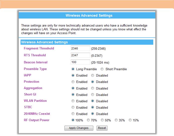
Advanced
Item / Function |
|
Descriptions / Instructions |
|
|
|
|
|
Fragment Threshold |
|
Fragmentation mechanism is used for improving the efficiency when high traffic flows along in the wireless network. |
|
|
|
If the 802.11g MIMO Wireless Router often transmit large files in wireless network, you can enter new Fragment |
|
|
|
|
|
|
|
Threshold value to split the packet. The value can be set from 256 to 2346. The default value is 2346. |
|
RTS Threshold |
|
RTS Threshold is a mechanism implemented to prevent the “Hidden Node” problem. If the “Hidden Node” problem is |
|
|
|
an issue, please specify the packet size. The RTS mechanism will be activated if the data size exceeds the value you |
|
|
|
set. |
|
|
|
Warning: Enabling RTS Threshold will cause redundant network overhead that could negatively affect the throughput |
|
|
|
performance instead of providing a remedy. |
|
|
|
This value should remain at its default setting of 2347. Should you encounter inconsistent data flow, only minor |
|
|
|
modifications of this value are recommended. |
|
|
|
|
|
Beacon Interval |
|
Beacon Interval is the amount of time between beacon transmissions. Before a station enters power save mode, the |
|
|
|
station needs the beacon interval to know when to wake up to receive the beacon. Range 20-1024 ms, default is 100. |
|
|
|
|
|
Preamble Type |
|
A preamble is a signal used in wireless environment to synchronize the transmitting timing including Synchronization |
|
|
|
and Start frame delimiter. You can select Long or Short for the preamble type. |
|
|
|
|
|
IAPP |
|
Select Enabled or Disabled to execute this function. |
|
Protection |
|
Select Enabled or Disabled to execute the security function. |
|
|
|
|
|
Aggregation |
|
Select Enabled or Disabled to execute this function. |
|
Short GI |
|
Select Enabled or Disabled to execute this function. |
|
|
|
|
|
WLAN Partition |
|
Select Enabled or Disabled to execute this function. |
|
STBC |
|
Select Enabled or Disabled to execute this function. |
|
|
|
|
|
20/40MHz Coexist |
|
Select Enabled or Disabled to execute this function. |
|
RF Output Power |
|
Select the transmitting power rate 100%, 70%, 50%, 35%, 15%. |
|
|
|
|
|
Version 1.00 |
17 |
English |
PROLiNK® WNR1008 |
www.prolink2u.com |
|
|
Security
|
|
|
|
|
|
PROLiNK_WNR1008 |
|
||
|
|
|
|
|
|
|
|
|
|
|
Item / Function |
|
Descriptions / Instructions |
||||||
|
|
|
|
|
|
|
|
|
|
|
Select SSID |
|
|
Select SSID (Service Set Identifier) to set up the security form the pull-down list. |
|
||||
|
|
|
|
||||||
|
|
|
|
|
|
|
|
|
|
|
Encryption |
|
There are several type of encryption modes including Disabled, WEP (Open System), WEP (Shared |
||||||
|
|
|
|
Key), WEP ( AUTO), WPA (Personal), WPA2 (Personal), and WPA-Mixed. The security default setting |
|||||
|
|
|
|
is Disabled. It is strongly recommended to set up security mode to prevent any unauthorized accessing. |
|||||
|
|
|
|
Note: |
|||||
|
|
|
|
AUTO (Open/Shared) means AP can accept client (station) to connect to it by using OPEN-WEP or |
|||||
|
|
|
|
SHARED-WEP. |
|||||
|
|
|
|
|
|
|
|
|
|
|
|
|
|
WEP |
|
|
|
|
|
|
|
|
|
Authentication: Select Open System, Shared Key or Auto. |
|||||
|
|
|
|
Key Length: select key length 64-bit or 128-bit. |
|||||
|
|
|
|
Key Format: |
|||||
|
|
|
|
Hexadecimal (WEP 64 bits): 10 Hex characters (0~9, a~f). |
|||||
|
|
|
Hexadecimal (WEP 128 bits): 26 Hex characters (0~9, a~f). |
||||||
|
|
|
ASCII (WEP 64 bits): 5 ASCII characters (case-sensitive). |
||||||
|
|
|
ASCII (WEP 128 bits): 13 ASCII characters (case-sensitive). |
||||||
|
|
|
Encryption Key: Enter the key in the key setting field. |
||||||
|
|
|
|
|
|
|
|
||
|
|
|
|
WPA-PSK/ WPA2-PSK/ WPA-PSK WPA2-PSK |
|
|
|||
|
|
|
|
|
|
|
|
|
|
Version 1.00 |
18 |
English |
PROLiNK® WNR1008 |
www.prolink2u.com |
|
|
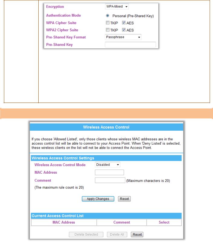
Authentication Mode: Select Enterprise (RADIUS) or Personal (Pre-Shared Key) mode. WPA Cipher Suite: here supported AES only.
WPA2 Cipher Suite: here supported AES only.
Pre-Shared Key Format: There are two formats for choice to set the Pre-shared key, Passphrase and Hex (64 characters). If Hex is selected, users will have to enter a 64 characters string. For easier configuration, the Passphrase (at least 8 characters) format is recommended.
Pre-Shared Key : Pre-Shared Key serves as a password. Users may key in 8 to 63 characters string if you selected passphrase. Pre-shared key format to set the passwords or leave it blank, in which the 802.1x Authentication will be activated. Make sure the same password is used on client's end.
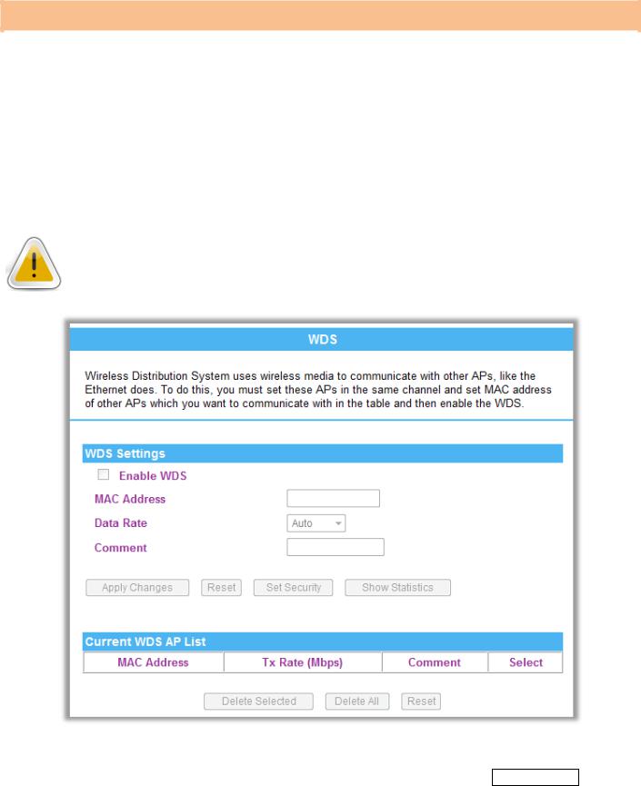
ACL
|
Item / Function |
|
Descriptions / Instructions |
|
||
|
|
|
|
|
|
|
|
Wireless Access |
|
|
Select Allow Listed or Deny Listed form the pull-down menu to enable access control function. Default setting is |
|
|
|
Control Mode |
|
|
Disabled. |
|
|
|
MAC Address |
|
Enter the MAC address (12 characters) of a station that is allowed to access this Access Point. |
|
||
|
|
|
|
|
||
|
Comment |
|
|
You may enter up to 20 characters as a remark to the previous MAC address. |
|
|
|
Current Access |
|
|
|
|
|
|
Control List |
|
This table displays you the station MAC information. |
|
||
|
|
|
|
|
||
|
|
|
|
|
|
|
|
Delete Selected |
|
|
Click |
Delete Selected to delete items which are selected. |
|
|
|
|
|
|
|
|
|
Delete All |
|
Click |
Delete All to delete all the items. |
|
|
|
|
|
|
|
|
|
|
Reset |
|
|
Click |
Reset to rest. |
|
|
|
|
|
|
|
|
|
|
|
|
|
|
|
Version 1.00 |
19 |
English |
PROLiNK® WNR1008 |
www.prolink2u.com |
|
|
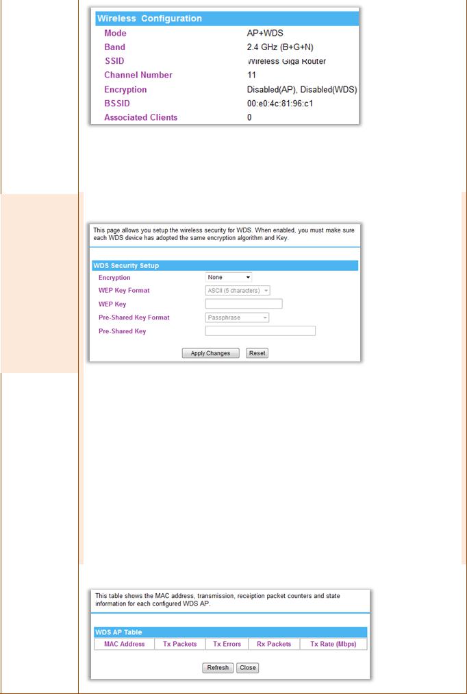
WDS
Wireless Distribution System uses wireless media to communicate with other APs, like the Ethernet does. To do this, you must set these APs in the same channel and set MAC address of other APs which you want to communicate with in the table and then enable the WDS.
To use WDS function:
1.The APs must support WDS function.
2.To set the same SSID (Network name).
3.The channel must be set to the same on the APs.
4.To set the same Wireless MAC address (BSSID) on the APs.
5.To set same security (WEP or WPA) on the APs.
Note: To setup WDS must use the same wireless products (the same model will be better); due to different wireless products might support different WDS settings. Thus, it is suggested that to use the same wireless products that support WDS function.
Step 1. Users would like to set up the WDS function, please go to Wireless > Basic page to set up the mode into WDS or AP+ WDS (Repeater) mode, and set the APs into the same Network Name (SSID) and Channel (If set to WDS mode, the SSID do not need to change). After setting up, please click Apply Changes button to execute.
Version 1.00 |
20 |
English |

PROLiNK® WNR1008 |
www.prolink2u.com |
|
|
1
2 PROLiNK_WNR1008
3
Step 2. Then go to Wireless > WDS page to (1) enable the WDS function and (2) enter APs Wireless MAC address (please go to Status> Wireless Configuration to make sure the BSSID) to each other to make the WDS
connection. Please click Apply button to execute.
1
2
Item / Function |
Descriptions / Instructions |
|
|
Enable WDS |
Check the box to enable the WDS function. |
|
|
|
MAC Address: Enter the Wireless BSSID (MAC) 12 characters of the wireless AP that you want to connect with. To |
MAC Address |
check your wireless router’s MAC address, please go to Status > Wireless Configuration to find your BSSID |
|
(Wireless MAC address.) |
|
|
Version 1.00 |
21 |
English |
PROLiNK® WNR1008 |
|
|
|
|
|
|
www.prolink2u.com |
||||
|
|
|
|
|
|
|
|
|
|
|
|
|
|
|
|
|
|
|
|
|
|
|
|
|
|
|
|
|
|
||||||
|
|
|
|
|
|
PROLiNK_WNR1008 |
|
||||
|
|
|
|
|
|
|
|
|
|
|
|
|
Data Rate |
|
|
Select the data rate form the pull-down list. |
|
|
|||||
|
Comment |
|
|
Enter a description for the device. |
|
||||||
|
|
|
|
|
|
|
|
|
|||
|
Apply Changes |
|
|
After completing the settings on this page, click Apply changes button to save the settings. |
|
|
|||||
|
Reset |
|
|
Click Reset to restore to default values. |
|
||||||
|
|
|
|
|
|
|
|
|
|
||
|
|
|
|
|
|
|
|
|
|
||
|
|
|
|
Enable the WDS function and then click |
Set Security |
button to set up the WDS security. |
|
|
|
||
|
|
|
|
|
|
|
|
|
|
|
|
|
|
Encryption: Select the encryption type None, WEP 64 bits, WEP 128 bits, and WPA2 (AES) from the pull-down |
|
Set Security |
|
|
|
|
|
menu. |
|
|
|
|
|
|
|
WEP Key Format: For WEP 64 bits and WEP 128 bits encryption type, the selection of WEP Key Format are Hex |
|
|
|
and ASCII. |
|
|
|
WEP Key: If select Hex if you are using hexadecimal numbers (0-9, or A-F). Select ASCII if you are using ASCII |
|
|
|
characters (case-sensitive). |
|
|
|
Hexadecimal (WEP 64 bits): 10 Hex characters (0~9, a~f). |
|
|
|
Hexadecimal (WEP 128 bits): 26 Hex characters (0~9, a~f). |
|
|
|
ASCII (WEP 64 bits): 5 ASCII characters (case-sensitive). |
|
|
|
ASCII (WEP 128 bits): 13 ASCII characters (case-sensitive). |
|
|
|
Pre-Shared Key Format: The Pre-shared Key Format will be enabled when WPA (TKIP) and WPA2 (AES) |
|
|
|
encryption be selected. There are two formats for choice to set the Pre-shared key, Passphrase and Hex (64 |
|
|
|
characters). If Hex is selected, users will have to enter a 64 characters string. For easier configuration, the |
|
|
|
Passphrase (at least 8 characters) format is recommended. |
|
|
|
Pre-Shared Key: Pre-Shared-Key serves as a password. Users may key in 8 to 63 characters string to set the |
|
|
|
passwords or leave it blank, in which the 802.1x Authentication will be activated. Make sure the same password is |
|
|
|
used on client's end. |
|
|
|
Click to show the current WDS AP table. This table shows the MAC address, transmission packets and errors, |
|
|
|
reception packets and Tx Rate (Mbps) counters for each configured WDS AP. |
|
Show Statistics
Version 1.00 |
22 |
English |
PROLiNK® WNR1008 |
|
www.prolink2u.com |
|||||
|
|
|
|
|
|
|
|
|
|
|
|
|
|
|
|
|
|
|
|
|
Refresh: Click to renew the counters information. |
|
|
|
|
|
|
|
Close: Click to leave the screen. |
|
|
|
|
|
|
|
|
|
|
|
|
Current WDS AP List |
|
|
Here shows the current WDS AP information. |
|
|
|
|
Delete Selected |
|
Click Delete Selected to delete the selected AP information. |
|
||
|
|
|
|
|
|
||
|
|
Delete All |
|
|
Click Delete All to delete all the items. |
|
|
|
|
|
|
|
|
|
|
|
|
Reset |
|
Click Reset to restore the settings. |
|
||
|
|
|
|
|
|
|
|
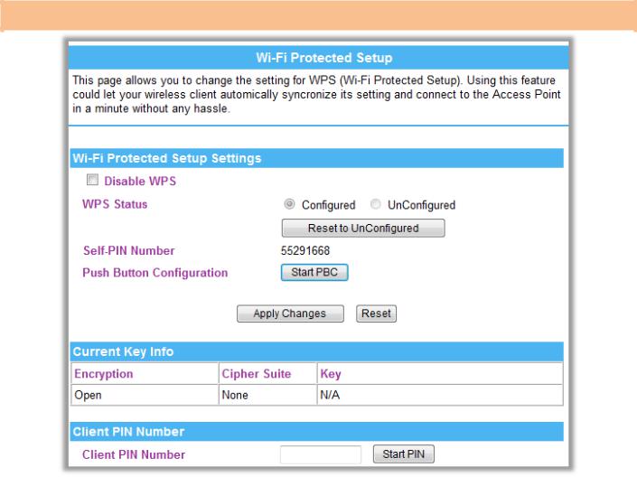
WPS
|
Item / Function |
|
Descriptions / Instructions |
|
|||||||
|
|
|
|
|
|
|
|
|
|
|
|
|
Disable WPS |
|
|
Check the box to disable the WPS function, default setting is enabled. |
|
||||||
|
WPS Status |
|
Here shows the current status of the WPS function. Default setting is Configured, click |
Reset to Unconfigured |
to re- |
|
|||||
|
|
configured the WPS connection. |
|
||||||||
|
|
|
|
|
|||||||
|
|
|
|
|
|
|
|
|
|||
|
Self-PIN Number |
|
|
Here shows the 8 characters PIN code of the router itself. |
|
||||||
|
Push Button |
|
|
|
|
|
|
|
|
|
|
|
|
Click |
Start PBC |
button to make a WPS connection with client. |
|
||||||
|
Configuration |
|
|
||||||||
|
|
|
|
|
|
|
|
|
|
||
|
|
|
|
|
|
|
|||||
|
Client PIN Number |
|
|
Enter the client PIN code into the blank field then click the |
Start PIN |
button to make a WPS connection with client. |
|
||||
|
|
|
|
|
|
|
|
|
|
|
|
Version 1.00 |
23 |
English |
PROLiNK® WNR1008 |
www.prolink2u.com |
|
|
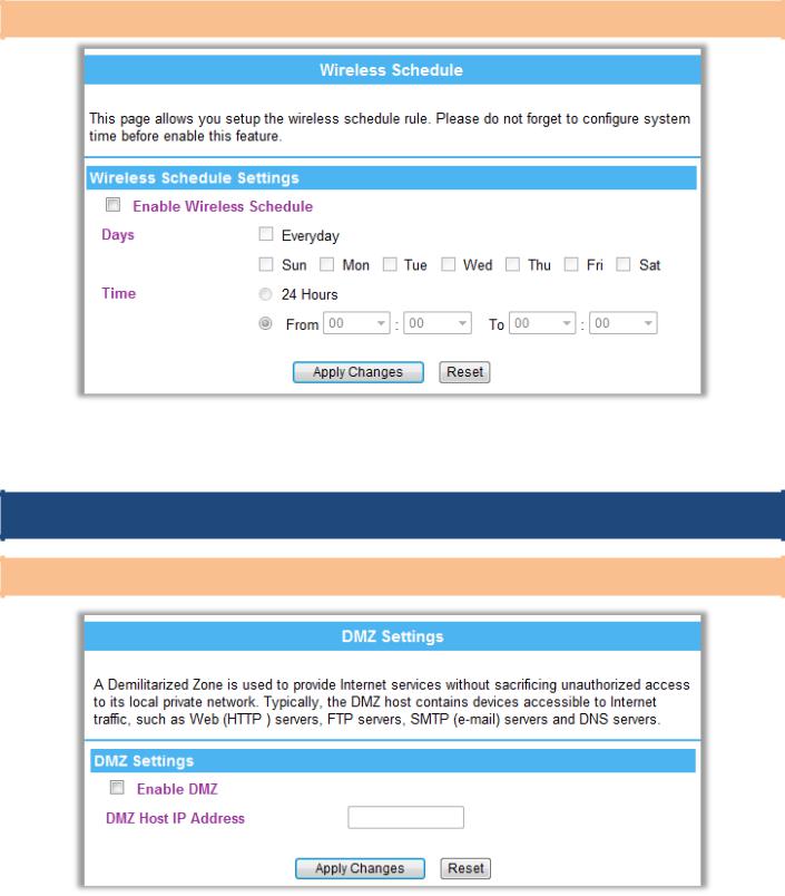
Schedule
Item / Function |
Descriptions / Instructions |
|
|
Enable Wireless |
Check the box to enable the schedule function. Set up the time to schedule the wireless access rule. Select the day |
Schedule |
and time you want to enable the wireless function. |
|
|
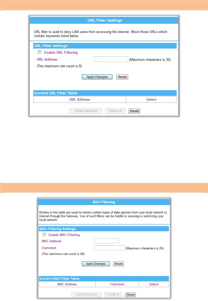
3.6.
DMZ Settings
Item / Function |
|
Descriptions / Instructions |
|
|
|
|
|
Enable DMZ |
|
Check the box to enable DMZ function. If the DMZ Host Function is enabled, it means that you set up DMZ host at a |
|
|
|
particular computer to be exposed to the Internet so that some applications/software, especially Internet / online |
|
|
|
|
|
|
|
game can have two way connections. |
|
DMZ Host IP |
|
Enter the IP address of a particular host in your LAN which will receive all the packets originally going to the WAN |
|
Address |
|
port/Public IP address above. |
|
|
|
Note: You need to give your LAN PC clients a fixed/static IP address for DMZ to work properly. |
|
|
|
|
|
Apply Changes |
|
After completing the settings on this page, click Apply Changes button to save the settings. |
|
Reset |
|
Click Reset button to restore to default values. |
|
|
|
|
|
Version 1.00 |
24 |
English |
PROLiNK® WNR1008 |
www.prolink2u.com |
|
|
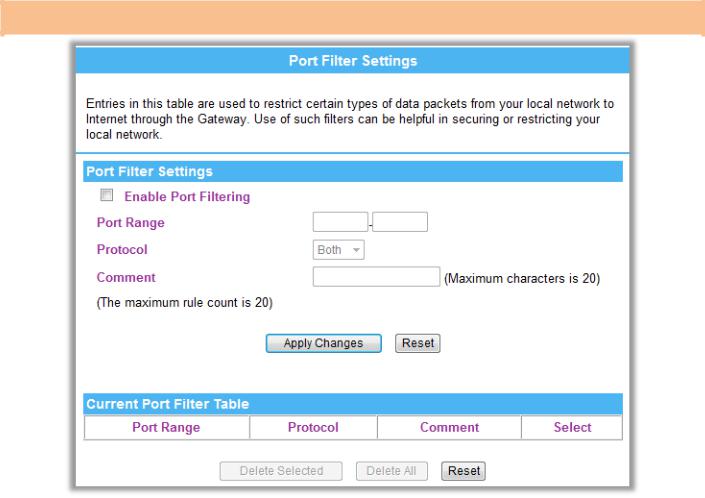
URL Filter Settings
|
Item / Function |
|
Descriptions / Instructions |
||
|
|
|
|
|
|
|
Enable URL Filtering |
|
|
Check to enable URL filtering function. |
|
|
URL Address |
|
Enter the URL address in the field. |
||
|
|
|
|
||
|
Apply Changes |
|
|
After completing the settings on this page, click Apply Changes button to save the settings. |
|
|
Reset |
|
Click Reset button to restore to default values. |
||
|
|
|
|
||
|
Current Filter Table |
|
|
Shows the current URL address filter information. |
|
|
Delete Selected |
|
Click Delete Selected button to delete items which are selected. |
||
|
|
|
|
||
|
Delete All |
|
|
Click Delete All button to delete all the items. |
|
|
Reset |
|
Click Reset button to rest. |
||
|
|
|
|
|
|
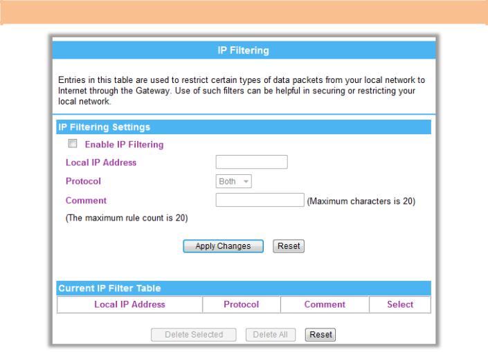
MAC Filtering
Version 1.00 |
25 |
English |
PROLiNK® WNR1008 |
|
www.prolink2u.com |
|||||
|
|
|
|
|
|
|
|
|
|
|
|
|
|
|
|
|
|
Item / Function |
|
Descriptions / Instructions |
|
||
|
|
|
|
|
|
|
|
|
|
Enable MAC Filtering |
|
Check to enable MAC filtering function. |
|
||
|
|
|
|
|
|
|
|
|
|
MAC Address |
|
|
Enter the client MAC address in the field. |
|
|
|
|
Comment |
|
You may key in a description MAC address. |
|
||
|
|
|
|
|
|
||
|
|
Apply Changes |
|
|
After completing the settings on this page, click Apply Changes button to save the settings. |
|
|
|
|
Reset |
|
Click Reset button to restore to default values. |
|
||
|
|
|
|
|
|
||
|
|
Current Filter Table |
|
|
Shows the current MAC filter information. |
|
|
|
|
Delete Selected |
|
Click Delete Selected button to delete items which are selected. |
|
||
|
|
|
|
|
|
||
|
|
Delete All |
|
|
Click Delete All button to delete all the items. |
|
|
|
|
Reset |
|
Click Reset button to rest. |
|
||
|
|
|
|
|
|
|
|
Port Filtering Settings
Item / Function |
Descriptions / Instructions |
|
|
Enable Port Filtering |
Check to enable Port Filtering function. |
Port Range |
Enter the beginning of the range of port numbers used by the service. If the service uses a single port number, enter |
|
it in both the start and finish fields. |
|
|
Protocol |
Select the protocol (TCP, UDP or Both) used to the remote system or service. |
Comment |
You may key in a description MAC address. |
|
|
Apply Changes |
After completing the settings on this page, click Apply Changes button to save the settings. |
Reset |
Click Reset button to restore to default values. |
|
|
Current Port |
Shows the current Port Forwarding information. |
Forwarding Table |
|
Delete Selected |
Click Delete Selected button to delete items which are selected. |
|
|
Delete All |
Click Delete All button to delete all the items. |
Reset |
Click Reset button to rest. |
|
|
Version 1.00 |
26 |
English |
PROLiNK® WNR1008 |
www.prolink2u.com |
|
|
IP Filtering
Item / Function |
Descriptions / Instructions |
|
|
Enable IP Filtering |
Check to enable IP filtering function. |
Local IP Address |
Enter the local server’s IP address. |
|
|
Protocol |
Select the protocol (TCP, UDP or Both) used to the remote system or service. |
Comment |
You may key in a description for the port range. |
|
|
Apply Changes |
After completing the settings on this page, click Apply Changes button to save the settings. |
Reset |
Click Reset button to restore to default values. |
|
|
Current Filter Table |
Shows the current IP filter information. |
Delete Selected |
Click Delete Selected button to delete items which are selected. |
|
|
Delete All |
Click Delete All button to delete all the items. |
Reset |
Click Reset button to rest. |
|
|
Version 1.00 |
27 |
English |
 Loading...