


XP 115
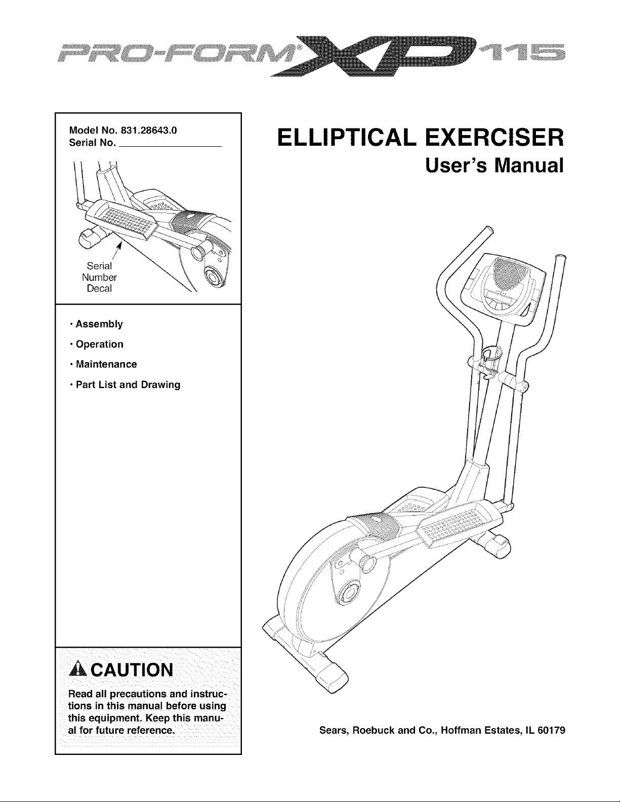
Model No. 831.28643.0
Serial No.
Serial
Number
Decal
• Assembly
• Operation
• Maintenance
• Part List and Drawing
CAUTION
Read all precautions and instruc-
tions in this manual before using
this equipment. Keep this manu-
al for future reference.
ELLIPTICAL EXERCISER
User's Manual
Sears, Roebuck and Co., Hoffman Estates, IL 60179
TABLE OF CONTENTS
IMPORTANT PRECAUTIONS ................................................................ 2
BEFORE YOU BEGIN ...................................................................... 3
ASSEMBLY ............................................................................... 4
HOW TO USE THE ELLIPTICAL EXERCISER ................................................... 8
MAINTENANCE AND TROUBLESHOOTING ................................................... 15
CONDITIONING GUIDELINES ............................................................... 16
PART LIST .............................................................................. 17
EXPLODED DRAWING .................................................................... 18
HOW TO ORDER REPLACEMENT PARTS ............................................. Back Cover
90 DAY FULL WARRANTY .......................................................... Back Cover
IMPORTANT PRECAUTIONS
'_ WARNING: To reduce the risk of serious injury, read the following important precau-
tions before using the elliptical exerciser.
1. Read all instructions in this manual and all 7. The elliptical exerciser should not be used
warnings on the elliptical exerciser before
using the elliptical exerciser. Use the ellipti-
cal exercise only as described in this
manual.
2. It is the responsibility of the owner to ensure
that all users of the elliptical exerciser are
adequately informed of all precautions.
3. The elliptical exerciser is intended for
home use only. Do not use the elliptical
by persons weighing more than 250 pounds.
8.
Wear appropriate exercise clothes when
using the elliptical exerciser. Always wear
athletic shoes for foot protection while exer-
cising.
9. Hold the handgrip pulse sensor or the han-
dlebars when mounting, dismounting, or
sing the elliptical exerciser.
4.
exerciser in a commercial, rental, or institu- 10. The pulse sensor is not a medical device.
tional setting. Various factors may affect the accuracy of
heart rate readings. The pulse sensor is
Keep the elliptical exerciser indoors, away intended only as an exercise aid in determin-
from moisture and dust. Place the elliptical ing heart rate trends in general.
exerciser on a level surface, with a mat
beneath it to protect the floor or carpet. 11. Keep your back straight while using the ellip-
Make sure that there is enough clearance tical exerciser; do not arch your back.
around the elliptical exerciser to mount, dis-
mount, and use it. 12. If you feel pain or dizziness while exercising,
stop immediately and cool down.
5. Inspect and properly tighten all parts regu-
larly. Replace any worn parts immediately.
6. Keep children under 12 and pets away from
the elliptical exerciser at all times.
13. When you stop exercising, allow the pedals
to slowly come to a stop.
_ WARNING: Before beginning this or any exercise program, consult your physician.
This is especially important for persons over the age of 35 or persons with pre-existing health prob-
lems. Read all instructions before using. Sears assumes no responsibility for personal injury or
property damage sustained by or through the use of this product.
2
BEFORE YOU BEGIN
Congratulations for selecting the new PROFORM ®XP
115 elliptical exerciser. The PROFORM XP 115 is an
incredibly smooth exerciser that moves your feet in a
natural elliptical path, minimizing the impact on your
knees and ankles. The unique XP 115 features
adjustable resistance and a state-of-the-art console to
help you get the most from your exercise.
For your benefit, read this manual carefully before
you use the elliptical exerciser. If you have ques-
tions after reading this manual, call 1-800-4-MY-
HOME _ (1-800-469-4663). To help us assist you,
please note the product model number and serial
number before calling. The model number is
831.28643.0. The serial number can be found on a
decal attached to the elliptical exerciser (see the front
cover of this manual for the location of the decal).
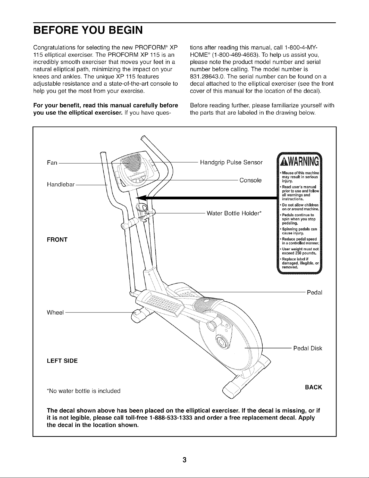
Before reading further, please familiarize yourself with
the parts that are labeled in the drawing below.
Fan
Handlebal
FRONT
Handgrip Pulse Sensor
Console
Water Bottle Holder*
=Misuseofthis machine
may result in serious
injury.
• Read user's manua_
prior to use and follow
all warningsand
instructions.
• Donot allow children
on or around machine.
, Pedals continue to
spin when you stop
pedaling.
=Spinning pedalscan
cause injury.
° Reduce pedal speed
in acontrolledmanner.
, Userweight must not
exceed 250 pounds.
• Replacelabel if
damaged, illegible,or
removed.
Pedal
Wheel
LEFT SIDE
Pedal Disk
*No water bottle is included
BACK
The decal shown above has been placed on the elliptical exerciser. If the decal is missing, or if
it is not legible, please call toll-free 1-888-533-1333 and order a free replacement decal. Apply
the decal in the location shown.
ASSEMBLY
Assembly requires two persons. Place all parts of the elliptical exerciser in a cleared area and remove the
packing materials. Do not dispose of the packing materials until assembly is completed. Assembly requires the
included hex keys as well as a phillips screwdriver _-__, an adjustable wrench
and a rubber mallet _ ............... 3 •
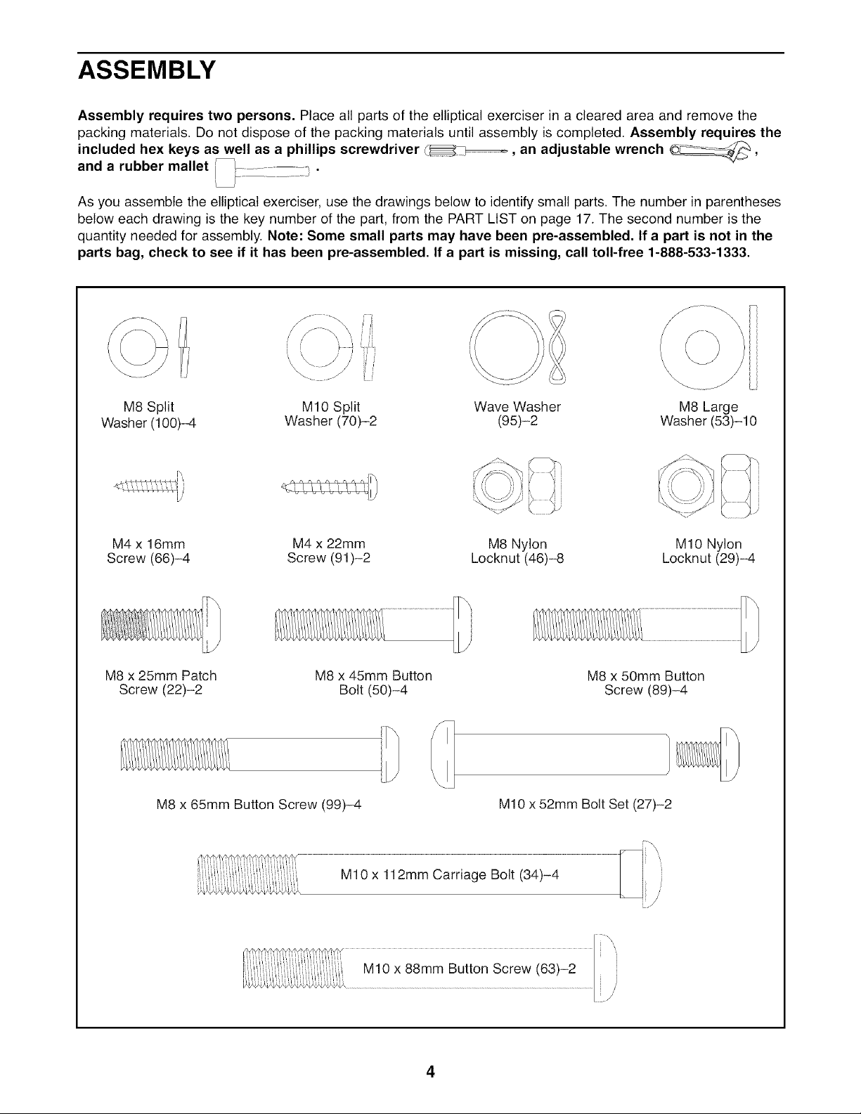
As you assemble the elliptical exerciser, use the drawings below to identify small parts. The number in parentheses
below each drawing is the key number of the part, from the PART LIST on page 17. The second number is the
quantity needed for assembly. Note: Some small parts may have been pre-assembled. If a part is not in the
parts bag, check to see if it has been pre-assembled. If a part is missing, call toll-free 1-888-533-1333.
\
\.
Wave Washer
(95)-2
M8 Split MIO Split M8 Large
Washer (100)-4 Washer (70)-2 Washer (53)-10
=,
M4 x 16mm M4 x 22mm M8 Nylon M10 Nylon
Screw (66)-4 Screw (91)-2 Locknut (46)-8 Locknut (29)-4
M8 x 25mm Patch
Screw (22)-2
M8 x 45mm Button
Bolt (50)-4
M8 x 50mm Button
Screw (89)-4
M8 x 65mm Button Screw (99)-4 M10 x 52mm Bolt Set (27)-2
4
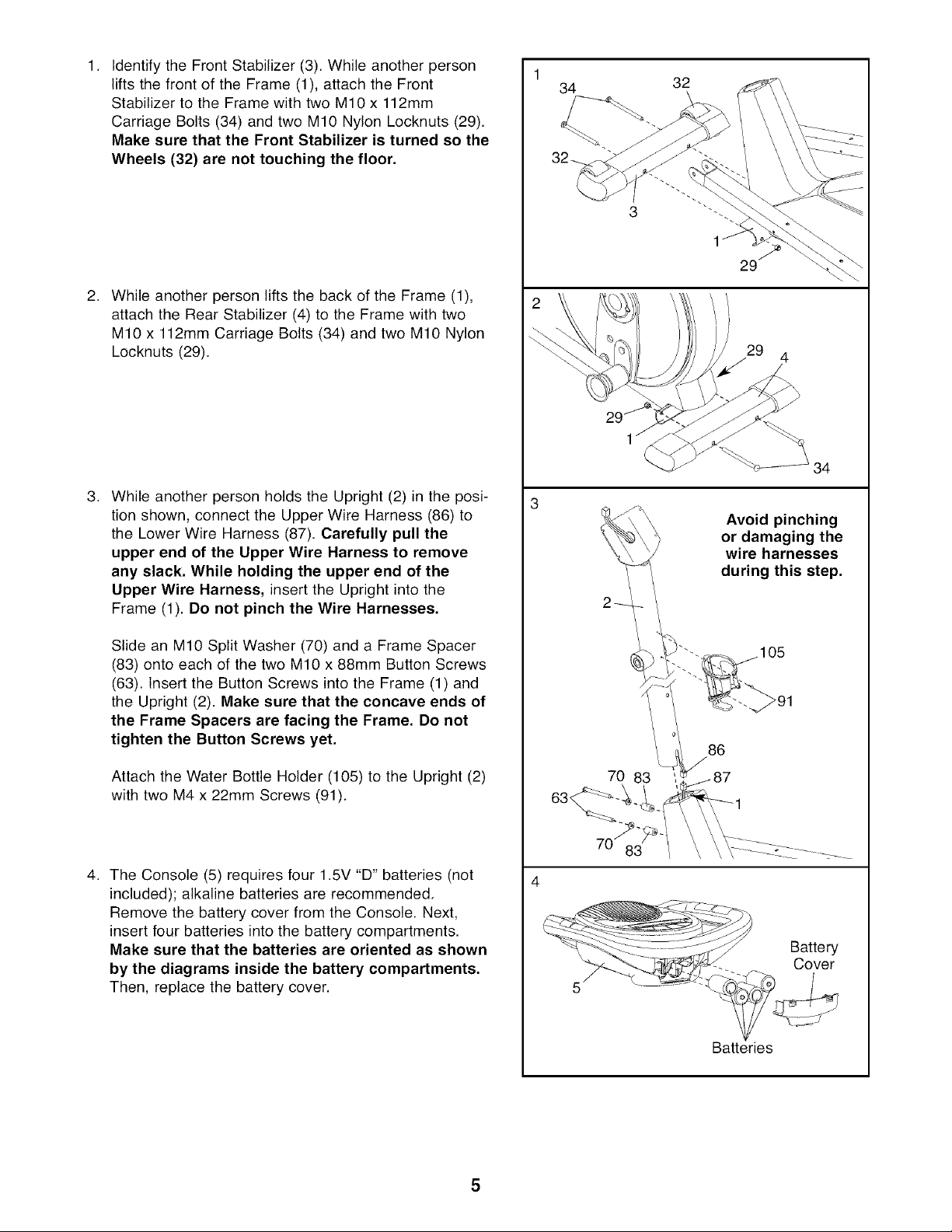
1.
Identify the Front Stabilizer (3). While another person
lifts the front of the Frame (1), attach the Front
Stabilizer to the Frame with two M10 x 112mm
Carriage Bolts (34) and two M10 Nylon Locknuts (29).
Make sure that the Front Stabilizer is turned so the
Wheels (32) are not touching the floor.
2,
While another person lifts the back of the Frame (1),
attach the Rear Stabilizer (4) to the Frame with two
M10 x 112mm Carriage Bolts (34) and two M10 Nylon
Locknuts (29).
.
While another person holds the Upright (2) in the posi-
tion shown, connect the Upper Wire Harness (86) to
the Lower Wire Harness (87). Carefully pull the
upper end of the Upper Wire Harness to remove
any slack, While holding the upper end of the
Upper Wire Harness, insert the Upright into the
Frame (1). Do not pinch the Wire Harnesses.
Slide an M10 Split Washer (70) and a Frame Spacer
(83) onto each of the two M10 x 88mm Button Screws
(63). Insert the Button Screws into the Frame (1) and
the Upright (2). Make sure that the concave ends of
the Frame Spacers are facing the Frame. Do not
tighten the Button Screws yet.
Attach the Water Bottle Holder (105) to the Upright (2)
with two M4 x 22mm Screws (91).
4. The Console (5) requires four 1.5V "D" batteries (not
included); alkaline batteries are recommended.
Remove the battery cover from the Console. Next,
insert four batteries into the battery compartments.
Make sure that the batteries are oriented as shown
by the diagrams inside the battery compartments.
Then, replace the battery cover.
1
34
32
3
29
29 4
Avoid pinching
or damaging the
wire harnesses
during this step.
86
70 83
Battery
Cover
Batteries
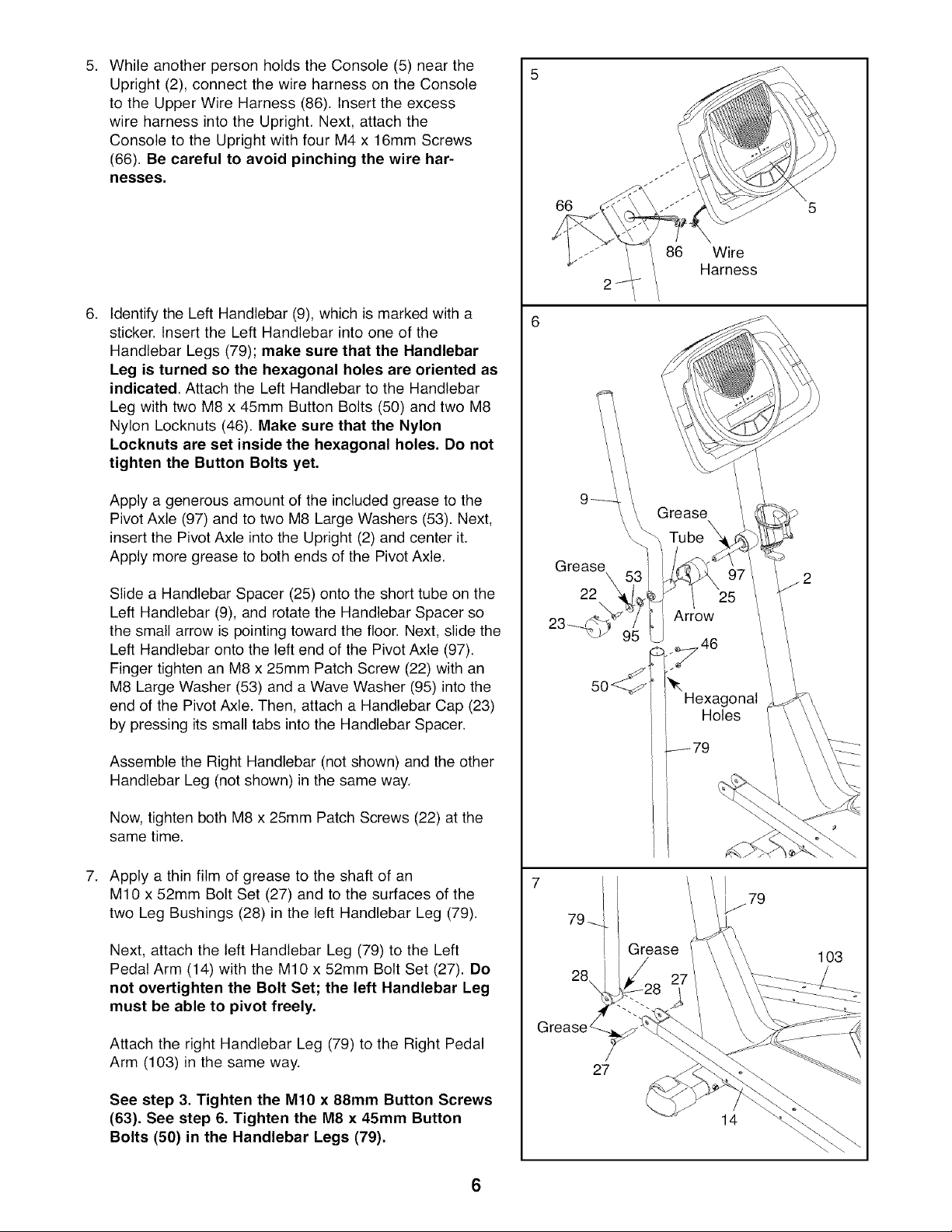
5. WhileanotherpersonholdstheConsole(5)nearthe
Upright(2),connectthewireharnessontheConsole
totheUpperWireHarness(86).Inserttheexcess
wireharnessintotheUpright.Next,attachthe
ConsoletotheUprightwithfourM4x16mmScrews
(66).Becarefulto avoidpinchingthewirehar-
nesses.
6. Identify the Left Handlebar (9), which is marked with a
sticker. Insert the Left Handlebar into one of the
Handlebar Legs (79); make sure that the Handlebar
Leg is turned so the hexagonal holes are oriented as
indicated. Attach the Left Handlebar to the Handlebar
Leg with two M8 x 45mm Button Bolts (50) and two M8
Nylon Locknuts (46). Make sure that the Nylon
Locknuts are set inside the hexagonal holes. Do not
tighten the Button Bolts yet,
Apply a generous amount of the included grease to the
Pivot Axle (97) and to two M8 Large Washers (53). Next,
insert the Pivot Axle into the Upright (2) and center it.
Apply more grease to both ends of the Pivot Axle.
Slide a Handlebar Spacer (25) onto the short tube on the
Left Handlebar (9), and rotate the Handlebar Spacer so
the small arrow is pointing toward the floor. Next, slide the
Left Handlebar onto the left end of the Pivot Axle (97).
Finger tighten an M8 x 25mm Patch Screw (22) with an
M8 Large Washer (53) and a Wave Washer (95) into the
end of the Pivot Axle. Then, attach a Handlebar Cap (23)
by pressing its small tabs into the Handlebar Spacer.
Assemble the Right Handlebar (not shown) and the other
Handlebar Leg (not shown) in the same way.
Now, tighten both M8 x 25mm Patch Screws (22) at the
same time.
7. Apply a thin film of grease to the shaft of an
M10 x 52mm Bolt Set (27) and to the surfaces of the
two Leg Bushings (28) in the left Handlebar Leg (79).
Next, attach the left Handlebar Leg (79) to the Left
Pedal Arm (14) with the M10 x 52mm Bolt Set (27). Do
not overtighten the Bolt Set; the left Handlebar Leg
must be able to pivot freely.
Attach the right Handlebar Leg (79) to the Right Pedal
Arm (103) in the same way.
See step 3. Tighten the M10 x 88mm Button Screws
(63). See step 6. Tighten the M8 x 45mm Button
Bolts (50) in the Handlebar Legs (79),
66
86 Wire
Harness
Grease 53
23 2--_,_i
5o !
Hexagonal
Holes
27
14
103
6
 Loading...