


proform.com
Model No. PFEX01418.0
Serial No.
Write the serial number in the space above for reference.


 Serial Number
Decal
ACTIVATE YOUR
WARRANTY
To register your product and activate your warranty today, go to my.proform.com.
CUSTOMER CARE
For service at any time, go to proformservice.com.
Or call 1-877-660-1168 Mon.–Fri. 6 a.m.–6 p.m. MT Sat. 8 a.m.–12 p.m. MT
Please do not contact the store.
 CAUTION
Read all precautions and instructions in this manual before using this equipment. Keep this manual for future reference.
USER’S MANUAL
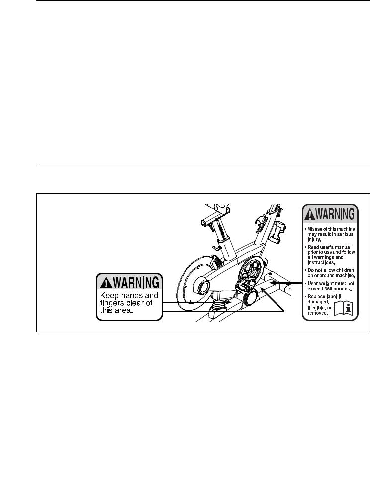
TABLE OF CONTENTS
WARNING DECAL PLACEMENT . . . . . . . . . |
. . . . . . . . . . . . . . . . . . |
. . . . . . . . . . . . |
. . . . . . . . . . . . . . . . . . . . . . . .2 |
IMPORTANT PRECAUTIONS. . . . . . . . . . . |
. . . . . . . . . . . . . . . . . |
. . . . . |
3 |
BEFORE YOU BEGIN. . . . . . . . . . . . . . . . . . . |
. . . . . . . . . . . . . . . . . . |
. . . . . . . . . . . |
. . . . . . . . . . . . . . . . . . . . . . . .6 |
PART IDENTIFICATION CHART. . . . . . . . . . . |
. . . . . . . . . . . . . . . . . . |
. . . . . . . . . . . . |
. . . . . . . . . . . . . . . . . . . . . . .7 |
ASSEMBLY . . . . . . . . . . . . . . . . . . . . . . . . . . . |
. . . . . . . . . . . . . . . . . . |
. . . . . . . . . . . . |
. . . . . . . . . . . . . . . . . . . . . . .8 |
HOW TO USE THE TRAINING BIKE . . . . |
. . . . . . . . . |
. . . . . . |
. . . . . . . . . . . 14 |
FCC INFORMATION . . . . . . . . . . . . . . . . . . . . |
. . . . . . . . . . . . . . . . . . |
. . . . . . . . . . . . |
. . . . . . . . . . . . . . . . . . . . . .29 |
MAINTENANCE AND TROUBLESHOOTING . |
. . . . . . . . . . . . . . . . |
. . . . . . . . . |
30 |
EXERCISE GUIDELINES. . . . . . . . |
. . . . . . . . . |
. . . . . . |
. . . . . . . . . . . .32 |
PART LIST. . . . . . . . . . . . . . . . . . . . . . . . . . . . |
. . . . . . . . . . . . . . . . . . |
. . . . . . . . . . . . |
. . . . . . . . . . . . . . . . . . . . . .33 |
EXPLODED DRAWING. . . . . . . . . . . . . . . . . . |
. . . . . . . . . . . . . . . . . . |
. . . . . . . . . . . . |
. . . . . . . . . . . . . . . . . . . . . .35 |
ORDERING REPLACEMENT PARTS. . . . . . . |
. . . . . . . . . . . . . . . . . . |
. . . . . . . . . . . . |
. . . . . . . . . . . . . . Back Cover |
LIMITED WARRANTY. . . . . . . . . . . . . . . . . . . |
. . . . . . . . . . . . . . . . . . |
. . . . . . . . . . . . |
. . . . . . . . . . . . . . Back Cover |
WARNING DECAL PLACEMENT
This drawing shows the location(s) of the warning decal(s). If a decal is missing or illegible, see the front cover of this manual and request a free replacement decal. Apply the decal in the location shown. Note: The decal(s) may not be
shown at actual size.
PROFORM and IFIT are registered trademarks of ICON Health & Fitness, Inc. LE TOUR DE FRANCE is a registered trademark of Société du Tour de France. Google Maps is a trademarks of Google LLC. The Bluetooth® word mark and logos are registered trademarks of Bluetooth SIG, Inc. and are used under license. Wi-Fi is a registered trademark of Wi-Fi Alliance. WPA and WPA2 are trademarks of Wi-Fi Alliance.
2

IMPORTANT PRECAUTIONS
 WARNING:To reduce the risk of burns, fire, electric shock, or injury to persons, read all important precautions and instructions in this manual and all warnings on your training bike before using your training bike. ICON assumes no responsibility for personal injury or property damage sustained by or through the use of this product.
1.It is the responsibility of the owner to ensure that all users of the training bike are adequately informed of all precautions.
2.Before beginning any exercise program, consult your physician. This is especially important for persons over age 35 or persons with pre-existing health problems.
3.The training bike is not intended for use by persons with reduced physical, sensory, or mental capabilities or lack of experience and knowledge, unless they are given supervision or instruction about use of the training bike by someone responsible for their safety.
4.Use the training bike only as described in this manual.
5.The training bike is intended for home use only. Do not use the training bike in a commercial, rental, or institutional setting.
6.Keep the training bike indoors, away from moisture and dust. Do not put the training bike in a garage or covered patio, or near water.
7.Place the training bike on a level surface with at least 2 ft. (0.6 m) of clearance around the training bike. To protect the floor or carpet from damage, place a mat under the training bike.
8.Inspect and properly tighten all parts each time the training bike is used. Replace any worn parts immediately.
9.Keep children under age 13 and pets away from the training bike at all times.
10.When connecting the power cord, plug the power cord into a grounded circuit.
11.Do not modify the power cord or use an adapter to connect the power cord to an improper receptacle. Keep the power cord away from heated surfaces. Do not use an extension cord.
12.Do not operate the training bike if the power cord or plug is damaged, or if the training bike is not working properly.
13.DANGER:Always unplug the power cord and press the power switch to the off position when the training bike is not in use and before cleaning the training bike. Servicing other than the procedures in this manual should be performed by an authorized service representative only.
14.Wear appropriate clothes while exercising; do not wear loose clothes that could become caught on the training bike. Always wear athletic shoes for foot protection.
3

15. |
The training bike should not be used by |
17. |
Always keep your back straight while using |
|
|
persons weighing more than 350 lbs. |
|
the training bike; do not arch your back. |
|
|
(159 kg). |
18. |
Over exercising may result in serious injury |
|
16. |
Be careful when mounting and dismounting |
|||
|
or death. If you feel faint, if you become short |
|||
|
the training bike. |
|
of breath, or if you experience pain while |
|
|
|
|
exercising, stop immediately and cool down. |
SAVE THESE INSTRUCTIONS
4

STANDARD SERVICE PLANS


 all
all
5
BEFORE YOU BEGIN
Congratulations for selecting the revolutionary PROFORM® LE TOUR DE FRANCE® training bike. The LE TOUR DE FRANCE training bike is unlike any ordinary exercise bike. With full adjustability, a Wi-Fi® cycling console, an incline system that simulates actual road terrain, and an array of other innovative features, the LE TOUR DE FRANCE training bike is designed to let you enjoy the outdoor cycling experience indoors.
For your benefit, read this manual carefully before you use the training bike. If you have questions after
reading this manual, please see the front cover of this manual. To help us assist you, note the product model number and serial number before contacting us. The model number and the location of the serial number decal are shown on the front cover of this manual.
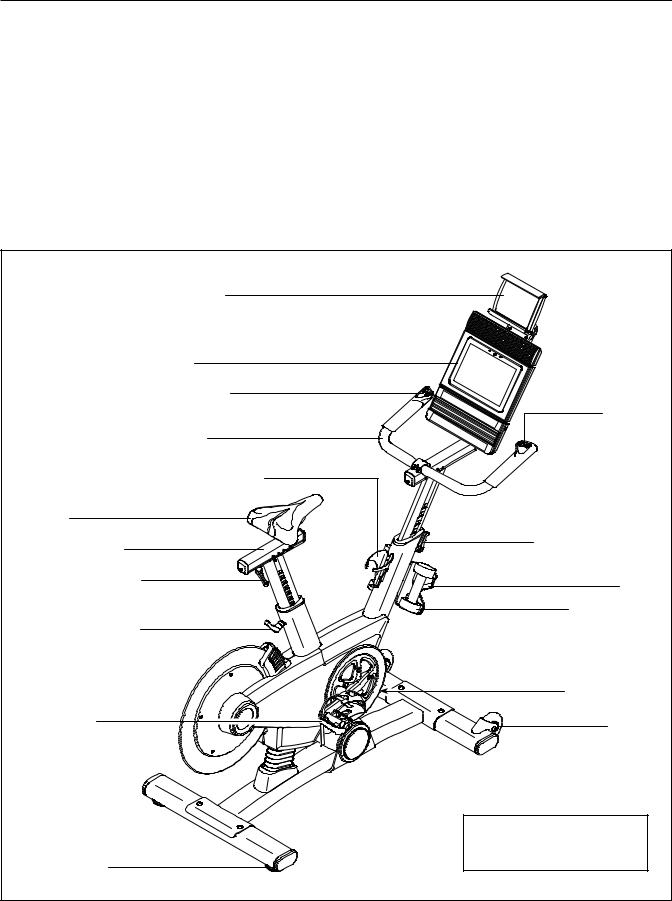
Before reading further, please familiarize yourself with the parts that are labeled in the drawing below.
Tablet Holder |
|
Console |
|
Incline Control |
Resistance |
|
Control |
Handlebar |
|
Water Bottle Holder* |
|
Saddle |
|
Saddle Carriage |
Adjustment Handle |
Adjustment Handle |
Tray |
|
|
Adjustment Handle |
Hand Weight |
|
|
|
Power Switch |
Pedal/Strap |
Wheel |
|
|
|
*Water bottle is not included |
|
Length: 5 ft. 5 in. (165 cm) |
Leveling Foot |
Width: 2 ft. 1 in. (64 cm) |
|
|
|
6 |

PART IDENTIFICATION CHART
Use the drawings below to identify the small parts needed for assembly. The number in parentheses below each
drawing is the key number of the part, from the PART LIST near the end of this manual. The number following the key number is the quantity needed for assembly. Note: If a part is not in the hardware kit, check to see if it has been preassembled. Extra parts may be included.
M4 x 10mm |
M4 x 12mm |
M4 x 14mm |
M4 x 16mm |
Tablet Holder |
Screw (116)–4 |
Screw (95)–2 |
Screw (117)–1 |
Screw (111)–4 |
Screw (113)–4 |
M6 x 16mm |
M10 x 58mm |
|
|
||
Screw (110)–4 |
M4 Washer |
|
|
Screw (74)–4 |
|
|
(54)–1 |
|
|
|
7
ASSEMBLY
•To hire an authorized service technician to assemble the training bike, call 1-800-445-2480.
•Assembly requires two persons.
•Place all parts in a cleared area and remove the packing materials. Do not dispose of the packing materials until you finish all assembly steps.
•Left parts are marked “L” or “Left” and right parts are marked “R” or “Right.”
•To identify small parts, see page 7.
•In addition to the included tool(s), assembly requires the following tools:
one Phillips screwdriver
Assembly may be easier if you have your own set of wrenches. To avoid damaging parts, do not use power tools.
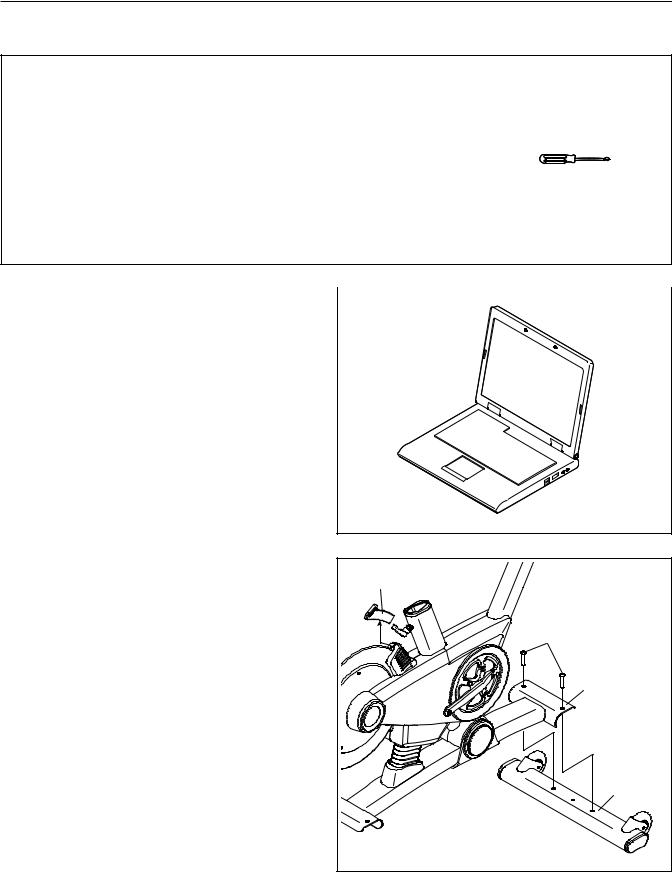
1. Go to my.proform.com on your computer and |
|
|
|
|
|
|
|
|
1 |
|
|
register your product. |
|
|
|
|
|
|
•documents your ownership
•activates your warranty
•ensures priority customer support if assistance is ever needed
Note: If you do not have internet access, call Customer Care (see the front cover of this manual) and register your product.
2. Remove and discard the indicated shipping |
2 |
|
|
insert (A). If there are shipping screws in the |
A |
||
|
|||
Front Stabilizer (22), remove and discard |
|
|
|
them. |
|
|
|
Attach the Front Stabilizer (22) to the Base (1) |
|
74 |
|
with two M10 x 58mm Screws (74). |
|
|
|
|
|
1 |
|
|
|
22 |
|
|
8 |
|
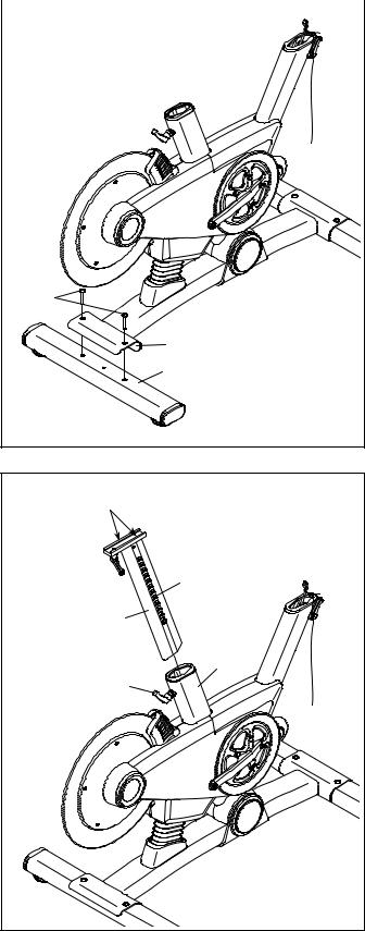
3. If there are shipping screws in the Rear |
|
|
|
|
|
|
|
|
3 |
|
|
Stabilizer (23), remove and discard them. |
|
|
|
|
|
|
Attach the Rear Stabilizer (23) to the Base (1) with two M10 x 58mm Screws (74).
|
|
74 |
|
|
|
1 |
|
|
|
23 |
|
4. Using a plastic bag to keep your fingers clean, |
4 |
|
|
apply some of the included grease to the sides |
Grease |
||
|
|||
of the channel on the top of the Saddle Post (3). |
|
|
|
Next, orient the Saddle Post (3) so that the |
|
|
|
height indicators (B) are on the side shown. |
|
B |
|
Loosen the indicated Adjustment Handle (47), |
|
||
|
3 |
||
and insert the Saddle Post (3) into the Frame (2). |
|
||
Move the Saddle Post upward or downward |
|
|
|
to the desired position, and then tighten the |
|
2 |
|
Adjustment Handle. IMPORTANT: When you |
|
||
|
47 |
||
are finished tightening the Adjustment |
|
||
Handle, make sure that the end of the |
|
|
|
Adjustment Handle is pointing upward. |
|
|
|
Note: The Adjustment Handle (47) functions |
|
|
|
like a ratchet. Turn the Adjustment Handle in |
|
|
|
the desired direction, pull it outward, turn it in |
|
|
|
the opposite direction, push it inward, and then |
|
|
|
turn it in the desired direction again. Repeat this |
|
|
|
process as many times as necessary. |
|
|
|
|
9 |
|
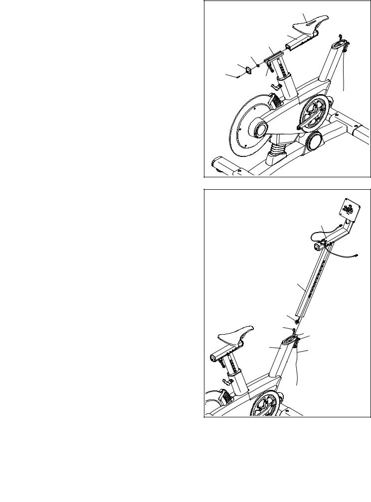
5.Note: You can attach your own saddle to the Saddle Carriage (4) if desired. Loosen the attachment hardware (not shown) beneath the Saddle (5), and remove the Saddle. Then, attach your own saddle and retighten the attachment hardware.
Orient the Saddle Carriage (4) as shown.
Loosen the indicated Adjustment Handle (47), and slide the Saddle Carriage (4) into the Saddle Post (3). Slide the Saddle Carriage to the desired position, and tighten the Adjustment Handle.
Then, attach an M4 Washer (54) and the Carriage Cover (91) to the Saddle Carriage (4) with an M4 x 14mm Screw (117).
6.See step 8. If the Handlebar Clamp (28) and four M6 x 16mm Screws (110) are preattached to the Handlebar Carriage (105), remove them and set them aside until step 8.
While a second person holds the Handlebar Post
(6) near the Frame (2), connect the Handlebar Post Wire (68) to the Frame Wire (130). Then, untie and discard the wire tie (C) on the Frame Wire. Insert the excess wire into the Frame.
Tip: Avoid pinching the wires. Loosen the indicated Adjustment Handle (47), and insert the Handlebar Post (6) into the Frame (2). Move the Handlebar Post upward or downward to the desired position, and tighten the Adjustment Handle.
5 |
|
5 |
|
|
|
|
|
4 |
|
|
3 |
|
|
54 |
|
|
91 |
|
117 |
47 |
|
|
|
6 |
|
|
|
|
105 |
|
|
6 |
Avoid pinching |
|
the wires |
68 |
|
|
|
130 |
|
47 |
2 |
C |
|
10
7.Have a second person hold the Handlebar (7) near the Handlebar Carriage (105).
Locate the wire tie (D) in the right side of the Handlebar (7). Tie the indicated end of the wire tie to the Right Control Wire (81), which is marked with a tag. Then, pull the other end of
the wire tie until the Right Control Wire is routed through the Handlebar. Then, untie and discard the wire tie.
Route the Left Control Wire (70) through the Handlebar (7) in the same way.
8.Tip: Avoid pinching the wires. Hold the Handlebar (7) on the Handlebar Carriage (105), and rotate the Handlebar to the desired angle; make sure that the Handlebar is centered on the Handlebar Carriage.
Attach the Handlebar (7) with the Handlebar Clamp (28) and four M6 x 16mm Screws (110); start all the Screws, and then tighten them.
9.Identify the Right Control (131), which is marked “Resistance.” Connect the wire on the Right Control to the Right Control Wire (81). Insert the excess wire into the Handlebar (7).
Tip: Avoid pinching the wires. Attach the Right Control (131) with an M4 x 12mm Screw (95).
Repeat this step for the Left Control (132).
7 |
|
70 |
|
|
|
|
|
D |
|
7 |
105 |
|
|
D |
|
|
81 |
|
|
7 |
|
|
D |
|
|
81 |
8 |
|
110 |
|
|
|
|
7 |
28 |
|
|
|
|
Avoid pinching |
|
|
the wires |
105 |
|
|
|
9 |
132 |
131 |
|
||
|
|
81 |
|
7 |
|
|
|
95 |
Avoid pinching the wires
11
 Loading...