


www.proform.com
Model No. PFEL18010.7
Serial No.
Write the serial number in the space above for reference.
ACTIVATE YOUR
WARRANTY
To register your product and activate your warranty today, go to www.proformservice.com/ registration.
CUSTOMER CARE
For service at any time, go to www.proformservice.com.
Or call 1-888-533-1333
Mon.BFri. 6 a.m.B6 p.m. MT
Sat. 8 a.m.B12 p.m. MT
Please do not contact the store.
USER%S MANUAL
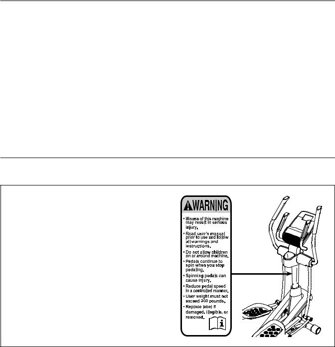
TABLE OF CONTENTS
WARNING DECAL PLACEMENT . . . . . . . . . . . . . . . . . . . . . . . . . . . . . . . . . . . . . . . . . . . . . . . . . . . . . . . . . . . . . . .2 IMPORTANT PRECAUTIONS. . . . . . . . . . . . . . . . . . . . . . . . . . . . . . . . . . . . . . . . . . . . . . . . . . . . . . . . . . . . . . . . . .3 BEFORE YOU BEGIN. . . . . . . . . . . . . . . . . . . . . . . . . . . . . . . . . . . . . . . . . . . . . . . . . . . . . . . . . . . . . . . . . . . . . . . .6 PART IDENTIFICATION CHART. . . . . . . . . . . . . . . . . . . . . . . . . . . . . . . . . . . . . . . . . . . . . . . . . . . . . . . . . . . . . . . .7 ASSEMBLY . . . . . . . . . . . . . . . . . . . . . . . . . . . . . . . . . . . . . . . . . . . . . . . . . . . . . . . . . . . . . . . . . . . . . . . . . . . . . . . .8 HOW TO USE THE ELLIPTICAL . . . . . . . . . . . . . . . . . . . . . . . . . . . . . . . . . . . . . . . . . . . . . . . . . . . . . . . . . . . . . .17 MAINTENANCE AND TROUBLESHOOTING . . . . . . . . . . . . . . . . . . . . . . . . . . . . . . . . . . . . . . . . . . . . . . . . . . . .28 EXERCISE GUIDELINES . . . . . . . . . . . . . . . . . . . . . . . . . . . . . . . . . . . . . . . . . . . . . . . . . . . . . . . . . . . . . . . . . . . .30 PART LIST. . . . . . . . . . . . . . . . . . . . . . . . . . . . . . . . . . . . . . . . . . . . . . . . . . . . . . . . . . . . . . . . . . . . . . . . . . . . . . . .31 EXPLODED DRAWING. . . . . . . . . . . . . . . . . . . . . . . . . . . . . . . . . . . . . . . . . . . . . . . . . . . . . . . . . . . . . . . . . . . . . .33 ORDERING REPLACEMENT PARTS . . . . . . . . . . . . . . . . . . . . . . . . . . . . . . . . . . . . . . . . . . . . . . . . . . Back Cover LIMITED WARRANTY. . . . . . . . . . . . . . . . . . . . . . . . . . . . . . . . . . . . . . . . . . . . . . . . . . . . . . . . . . . . . . . Back Cover
WARNING DECAL PLACEMENT
This drawing shows the location(s) of the warning decal(s). If a decal is missing or illegible, see the front cover of this manual and request a free replacement decal. Apply the decal in the location shown. Note: The decal(s) may not be shown at actual size.
PROFORM is a registered trademark of ICON IP, Inc.
2

IMPORTANT PRECAUTIONS
 WARNING: To reduce the risk of burns, fire, electric shock, or injury to persons, read all important precautions and instructions in this manual and all warnings on your elliptical before using your elliptical. ICON assumes no responsibility for personal injury or property damage sustained by or through the use of this product.
1.It is the responsibility of the owner to ensure that all users of the elliptical are adequately informed of all precautions.
2.Before beginning any exercise program, consult your physician. This is especially important for persons over age 35 or persons with pre-existing health problems.
3.Use the elliptical only as described in this manual.
4.The elliptical is intended for home use only. Do not use the elliptical in a commercial, rental, or institutional setting.
5.Keep the elliptical indoors, away from moisture and dust. Do not put the elliptical in a garage or covered patio, or near water.
6.Place the elliptical on a level surface, with at least 3 ft. (0.9 m) of clearance in the front and rear of the elliptical and 2 ft. (0.6 m) on each side. To protect the floor or carpet from damage, place a mat under the elliptical.
7.Inspect and properly tighten all parts regularly. Replace any worn parts immediately.
8.Keep children under age 12 and pets away from the elliptical at all times.
9.When connecting the power cord, plug the power cord into a grounded circuit.
10.Do not modify the power cord or use an adapter to connect the power cord to an improper receptacle. Keep the power cord away from heated surfaces. Do not use an extension cord.
11.Do not operate the elliptical if the power cord or plug is damaged, or if the elliptical is not working properly.
12. DANGER: Always unplug the power cord and switch the power switch to the off position when the elliptical is not in use and before cleaning the elliptical. Servicing other than the procedures in this manual should be performed by an authorized service representative only.
13.The elliptical should not be used by persons weighing more than 300 lbs. (136 kg).
14.Wear appropriate clothes while exercising; do not wear loose clothes that could become caught on the elliptical. Always wear athletic shoes for foot protection while exercising.
15.Hold the handlebars or the upper body arms when mounting, dismounting, or using the elliptical.
16.The heart rate monitor is not a medical device. Various factors may affect the accuracy of heart rate readings. The heart rate monitor is intended only as an exercise aid in determining heart rate trends in general.
17.The elliptical does not have a freewheel; the pedals will continue to move until the flywheel stops. Reduce your pedaling speed in a controlled way.
18.Keep your back straight while using the elliptical; do not arch your back.
19.Over exercising may result in serious injury or death. If you feel faint or if you experience pain while exercising, stop immediately and cool down.
SAVE THESE INSTRUCTIONS
3

4

STANDARD SERVICE PLANS


 all
all
5
BEFORE YOU BEGIN
Thank you for selecting the revolutionary PROFORM® 14.0 CE elliptical. The 14.0 CE elliptical provides an impressive selection of features designed to make your workouts at home more effective and enjoyable.
For your benefit, read this manual carefully before you use the elliptical. If you have questions after reading this manual, please see the front cover of this
manual. To help us assist you, note the product model number and serial number before contacting us. The model number and the location of the serial number decal are shown on the front cover of this manual.
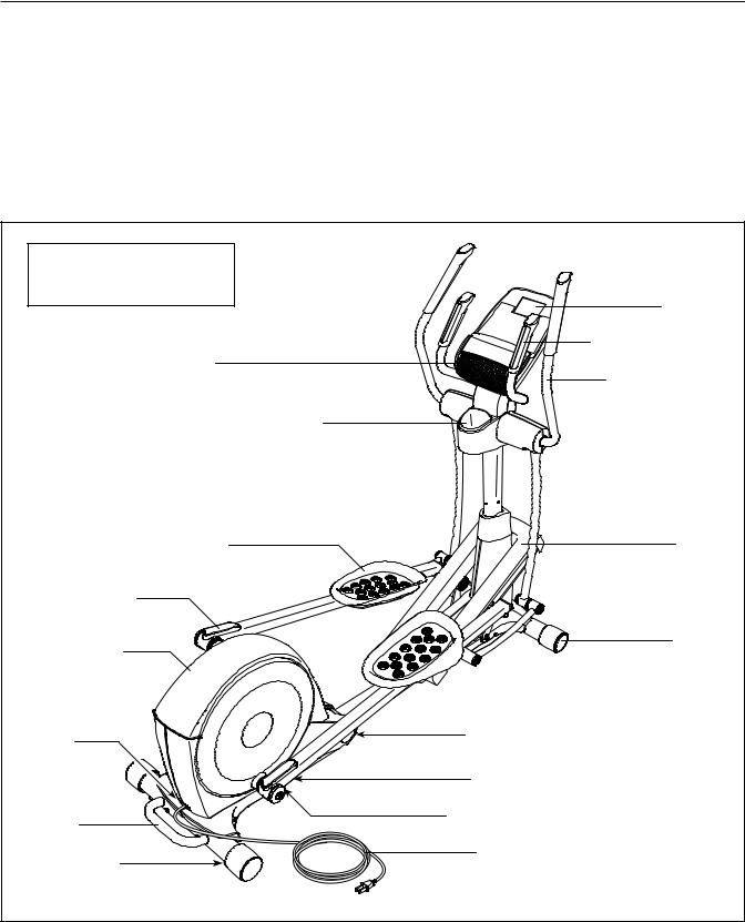
Before reading further, please familiarize yourself with the parts that are labeled in the drawing below.
Length: 5 ft. 6 in. (168 cm) |
|
|
Width: 2 ft. 3 in. (69 cm) |
Console |
|
|
||
Fan |
Heart Rate Monitor |
|
Upper Body Arm |
||
|
||
Water Bottle Holder* |
|
|
Pedal |
Ramp |
|
Storage Magnet |
|
|
Access Cover |
Wheel |
|
|
||
Power |
Leveling Foot |
|
Switch |
||
|
||
|
Latch Button |
|
Handle |
Pedal Arm Latch |
|
|
||
Leveling Foot |
Power Cord |
|
|
||
|
*Water bottle is not included |
|
|
6 |
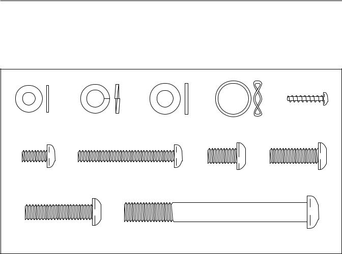
PART IDENTIFICATION CHART
Use the drawings below to identify the small parts needed for assembly. The number in parentheses below each drawing is the key number of the part, from the PART LIST near the end of this manual. The number following the key number is the quantity needed for assembly. Note: If a part is not in the hardware kit, check to see if it has been preassembled. Extra parts may be included.
M6 Washer |
M8 Split Washer |
M8 Washer |
Wave Washer |
M4 x 19mm |
(112)B8 |
(103)B14 |
(95)B6 |
(118)B2 |
Screw (80)B8 |
M6 x 12mm |
M6 x 50mm |
|
M8 x 16mm |
M8 x 25mm |
Screw (111)B4 |
Screw (62)B4 |
|
Screw (102)B16 |
Screw (121)B2 |
M8 x 35mm |
|
M10 x 95mm |
|
|
Screw (92)B2 |
|
Screw (100)B4 |
|
|
7
ASSEMBLY
dTo hire an authorized service technician to assemble this product, call 1-800-445-2480.
dAssembly requires two persons.
dPlace all parts in a cleared area and remove the packing materials. Do not dispose of the packing materials until you nish all assembly steps.
dLeft parts are marked eLf or eLeftf and right parts are marked eRf or eRight.f
dTo identify small parts, see page 7.
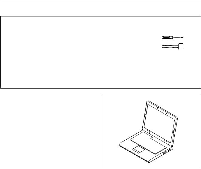
dIn addition to the included tool(s), assembly requires the following tools:
one Phillips screwdriver
one rubber mallet
Assembly may be easier if you have a set of wrenches. To avoid damaging parts, do not use power tools.
1. Go to www.proformservice.com/registration |
|
|
|
|
1 |
|
|
on your computer and register your product. |
|
|
|
|
|
|
dactivates your warranty
dsaves you time if you ever need to contact Customer Care
dallows us to notify you of upgrades and offers
Note: If you do not have Internet access, call Customer Care (see the front cover of this manual) and register your product.
8
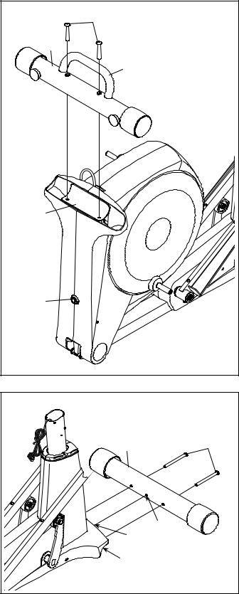
2. Orient the Rear Stabilizer (4) as shown. |
2 |
|
Attach the Rear Stabilizer (4) to the Folding |
100 |
|
|
|
|
Frame (2) with two M10 x 95mm Screws (100). |
4 |
|
|
|
|
Next, hold the handle on the Rear Stabilizer (4), |
Handle |
|
press the Latch Button (67), and lower the Rear |
|
|
|
|
|
Stabilizer and the Folding Frame (2) to the floor. |
|
|
|
2 |
|
|
67 |
|
3. Orient the Front Stabilizer (3) so that the |
3 |
|
indicated hole is facing the pin on the Main |
|
|
|
|
|
Frame (1). |
|
|
While a second person lifts the front of the Main |
3 |
100 |
Frame (1), attach the Front Stabilizer (3) with |
|
|
two M10 x 95mm Screws (100). |
|
|
|
Hole |
|
|
Pin |
|
|
1 |
|
|
9 |
|
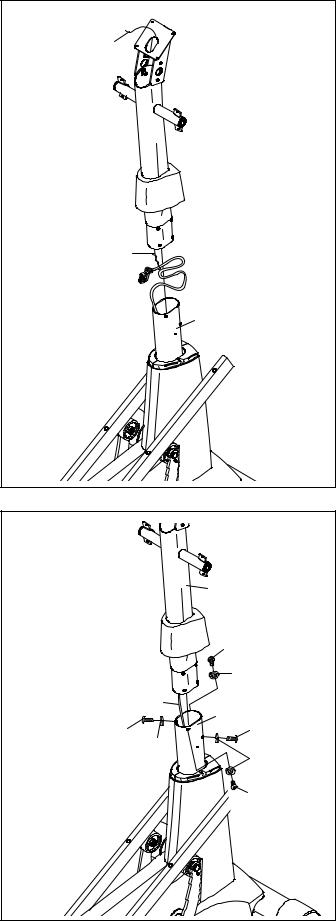
4. Identify and orient the Upright (5) and the Top |
|
|
4 |
||
Cover (27) as shown. |
||
|
||
Slide the Top Cover (27) upward onto the |
|
|
Upright (5). |
|
|
Have a second person hold the Upright (5) and |
|
|
the Top Cover (27) near the Main Frame (1). |
|
|
Locate the wire tie in the Upright (5). Tie the |
|
|
lower end of the wire tie to the Wire Harness |
|
|
(60). Next, pull the upper end of the wire tie until |
|
|
the Wire Harness is routed through the Upright. |
|
Tip: To prevent the Wire Harness (60) from falling into the Upright (5), secure the Wire Harness with the wire tie.
Wire Tie
 5
5
 27
27
Wire Tie
60
1
5. Tip: Avoid pinching the Wire Harness (60).
Insert the Upright (5) into the Main Frame (1).
Attach the Upright (5) with four M8 x 16mm Screws (102) and four M8 Split Washers (103); do not tighten the Screws yet.
5 |
|
|
|
5 |
|
Avoid pinching the |
|
|
Wire Harness (60) |
102 |
|
|
||
|
103 |
|
|
60 |
|
|
1 |
|
102 |
102 |
|
103 |
||
|
||
|
103 |
|
|
102 |
|
10 |
|
6. Using a small plastic bag to keep your |
6 |
|
|
|
fingers clean, apply a coat of the included |
|
|
||
60 |
|
|
||
grease to the Upright Axle (48) and to two Wave |
|
|
||
102 |
|
|
||
Washers (118). |
|
Avoid damaging the |
||
Tip: Avoid damaging the Wire Harness (60). |
118 |
|||
Wire Harness (60) |
||||
Insert the Upright Axle (48) through the Upright |
95 |
5 |
|
|
(5) and center it. Slide a Wave Washer (118) |
|
|
||
|
|
|
||
onto each side of the Upright Axle. |
7 |
48 |
Grease |
|
Next, identify the Right and Left Upper Body |
Grease |
|
|
|
|
|
118 |
||
Legs (6, 7) and orient them as shown. |
|
|
||
Slide the Right and Left Upper Body Legs |
|
|
102 |
|
(6, 7) onto the right and left sides of the Upright |
|
|
|
|
Axle (48). |
|
|
95 |
|
Tighten an M8 x 16mm Screw (102) and an M8 |
|
|
6 |
|
Washer (95) into each end of the Upright Axle |
|
|
|
|
(48) at the same time. |
|
|
|
|
7. Identify the Right Pedal (14), the Right Gel Pad |
7 |
|
|
|
(90), and the Right Pedal Arm (12) assembly and |
|
|
||
|
|
|
||
orient them as shown. |
14 |
|
|
|
Set the Right Gel Pad (90) on the Right Pedal |
|
|
||
|
|
|
||
Arm (12). Then, set the Right Pedal (14) on the |
|
|
|
|
Right Gel Pad. |
|
|
|
|
Attach the Right Pedal (14) to the Right Pedal |
|
|
|
|
Arm (12) with two M6 x 12mm Screws (111) |
|
|
|
|
and two M6 Washers (112); do not tighten the |
|
|
|
|
Screws yet. |
90 |
|
|
|
|
|
|
||
Next, tighten two M6 x 50mm Screws (62) with |
|
|
|
|
two M6 Washers (112) into the Right Pedal Arm |
|
|
|
|
(12) and the Right Pedal (14). Then, tighten the |
12 |
|
|
|
two M6 x 12mm Screws (111). |
|
112 |
||
|
|
|||
|
|
|
||
Attach the Left Pedal (not shown) to the Left |
|
112 |
62 |
|
Pedal Arm (not shown) assembly in the same |
|
111 |
||
way. |
|
|
|
|
|
11 |
|
|
|
 Loading...