Precor PVS-15 User Manual

PVS-15
Personal Viewing System
Assembly and Operation Manual
Cardio Theater Holdings, Inc. 21420-D NW Nicholas Court #12-13 Hillsboro, OR 97124
(800) 776-6695
(503) 645-8881 www.cardiotheater.com
TABLE OF CONTENTS
Parts List…………………………………...Page 2
Stand Assembly………………..………… Page 3-4
DVD Player Assembly………..…………..Page 5-7
LCD Screen Assembly………………..….Page 8-9
Mounting Screen Controller…………..….Page 10
Programming TV Channels………….…..Page 11
Cable Management……………………….Page 12
RF Distribution…………………………….Page 13
Specifications…………………………….. Page 14
Warranty……………………………………Page 15
Technical Support…………………………Page 16
1
Parts List:
Master Set Up Package
1 |
Master IR Remote Control |
1Operations Manual
Screen Controllers (1 for each Screen)
1 |
Neoprene Mounting Pad (1 for each controller) |
1 |
DVD Player Master IR Remote (Optional) |
Screen Box |
|
1 |
15 inch LCD Screen |
1 |
AC Adapter |
1 |
Adapter Power Cord |
1 |
LCD Back Cover |
1 |
Controller Cable |
1 |
LCD Screen Hardware Package |
4 |
Wire Ties |
Stand Box |
|
2 |
Stand Feet |
1 |
Base Cross Bar |
1 |
Lower Vertical Tube |
1 |
Upper Vertical Tube (Short or Long Model) |
1 |
Base Cover |
1 |
Coax / Power Cable |
8 |
Hex Screws |
DVD Player Box (Optional) |
|
1 |
DVD Player |
1 |
12 Volt Power Cable |
1 |
Audio / Video RCA Patch Cord |
DVD Bracket (Optional) |
|
1 |
Long or Short Bracket (as ordered) |
1 |
Back Cover (Short Version Only) |
1 |
DVD Hardware Package |
2

Stand Assembly
Step 1 |
Step 2 |
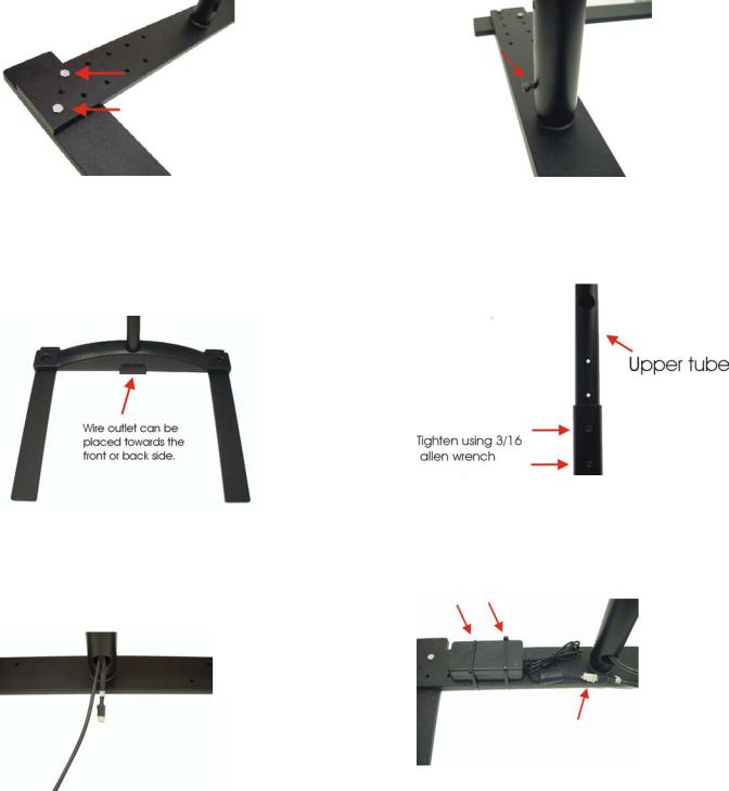
Determine width of stand feet in relation to the cardio equipment. Use a 7/16 wrench to secure 2 hex screws per leg.
Step 3
Insert plastic base cover over lower vertical tube. Do not fasten down at this time.
Step 5
Insert cable assemblies through upper tube opening and bring out lower tube hole as shown.
3
Insert lower vertical tube over center stub and hand install one 3/16 Allen head screw a few turns into vertical tube. Do not tighten at this time. (Clearance needed for Wires)
Step 4
Insert upper curved tube into lower tube. Do not install bolts until step 5 is performed, then adjust upper tube to desired height and install two Allen screws as shown above.
Step 6
Mount power supply with 2 wire ties to the base assembly. Plug power supply connector into cable previously installed down vertical tube.

Stand assemblycontinued
Step 7 |
Step 8 |
|
Route coax and AC power plug to center
Opening of base cover and make sure to tighten lower bolt before installing cover.
With cables properly placed in cover slot, secure base cover with 2 Allen head screws provided.
Step 9
Install last remaining Screw in upper tube Assembly and double-check all Fasteners for Tightness.
4

DVD Player Assembly
NOTE: Skip to Page 7 if not installing DVD Player
Important: There are two models of DVD brackets.
Short DVD Bracket |
Long DVD Bracket |
For S Model Stand |
For L Model Stand |
1:Run supplied Audio Video cable and DVD 12 Volt Power cable from opening at top of stand out through large round hole in upper tube of stand.
5
 Loading...