


Uninterruptible Power Supply
SOLA 4000
OPERATING MANUAL
JUE 401263

Contents of JUE 401263
SOLA 4000 Operating Manual
The SOLA 4000 Operating Manual consists of the following documents:
SECTION 0: |
JUE 401263 |
INDEX AND SAFETY INSTRUCTIONS |
SECTION 1: |
JUE 401264 |
GENERAL SYSTEM DESCRIPTION |
SECTION 2: |
JUE 401265 |
INSTALLATION AND INITIAL START-UP |
SECTION 3: |
JUE 401266 |
OPERATION |
SECTION 4: |
JUE 401267 |
OPERATING PANEL |
SECTION 5: |
JUE 401268 |
PCB DESCRIPTION |
SECTION 6: |
JUE 401269 |
TECHNICAL DATA |
We reserve the right to modify the contents of this document without notice. BEST POWER- BORRI ELETTRONICA INDUSTRIALE S.r.l Via 8 Marzo Soci, Bibbiena (AREZZO)
ISSUED |
04.02.97 |
M. Porpora |
04.02.97 |
A4 |
1 |
3 |
|
A See Rev. Doc. JSE401440 |
20.06.97 |
||||||
T. Boon |
|
||||||
|
|
|
|
||||
|
|
T. Boon |
|
JUE 401263 |
|||

SOLA 4000 - Operating Manual
Safety Instructions
SAFETY INSTRUCTIONS
The unit must be used as intended. Follow the instructions given in the Operating Manual.
Dangerous voltages are present inside the unit.
Installation and use of this equipment must comply to all national and local regulations and procedures.
To prevent overheating do not obstruct the flow of air for ventilation openings to the unit.
The components inside the unit are not repairable by the user. The user must not open the UPS cabinet or auxiliary cabinets or remove any protective covers from inside the UPS cabinet.
This equipment must be installed and serviced by qualified personnel.
The unit contains Lead-Acid batteries which must be disposed of correctly, in compliance with the local regulations.
To completely isolate the equipment, the switches IRP, IRE, IBY,IUG and IB must be switched off, the input supply and the battery supply must be isolated from the UPS and the output isolated from other modules if the unit is part of a multi-module system. For 10-30kVA units with an internal battery, intermediate links must be removed in order to isolate the battery in sections of a safe working voltage.
High leakage current: connect protective earth before power supply cables.
JUE 401263 |
3 |

SOLA 4000 - Operating Manual
Safety Instructions
Earth leakage protection: this device has a high leakage current towards protective earthing. The maximum earth leakage current is 300 mA. When setting the threshold of the earth leakage circuit breaker installed upstream from this equipment consider this amount of current and that due to the loads.
All primary power switches installed downstream of the UPS must be labelled as follows: "Isolate UPS (Uninterruptible Power Supply) before working on this circuit.
The unit is provided with the E.P.O. (Emergency Power Off) function. This function is activated by pressing simultaneously the two push buttons on the bottom part of the Front Panel. This function provides UPS disconnection from the load and from the battery. Dangerous voltages will still be present inside the unit, if a shunt-trip of the input supply switch is not provided for.
During electrolysis, batteries release hydrogen gas. There is a risk of an explosion if the amount of hydrogen in the battery room becomes too high. Ensure appropriate ventilation of the battery room according to the standard EN50091-1, to prevent the risk of an explosion.
JUE 401263 |
4 |

Contents of JUE 401264
SOLA 4000 - General System Description
|
|
Chapters |
|
|
|
Figures |
|
1 |
UPS ASSEMBLY |
2 |
|
|
|
|
|
|
|
|
|
|
|
|
|
|
1.1 |
Features |
2 |
FIG. 1.1 |
UPS Block-Diagram |
3 |
|
|
1.2 |
UPS System Structure |
3 |
FIG. 1.2 |
Rectifier Block-Diagram |
3 |
|
|
1.3 |
Rectifier/Battery Charger |
3 |
FIG. 1.3 |
12-Pulse Rectifier Block-Diagram |
3 |
|
|
1.4 |
Battery (Accumulator) |
4 |
FIG. 1.4 |
Inverter Block-Diagram |
4 |
|
|
1.5 |
Inverter |
4 |
FIG. 1.5 |
Static Switches Block-Diagram |
4 |
|
|
1.6 |
Static Switches |
4 |
FIG. 1.6 |
Maintenance Bypass Block-Diagram |
6 |
|
|
1.7 |
Maintenance Bypass |
6 |
FIG. 1.6.1 Wall-mounted Maintenance Bypass |
|
||
|
1.8 |
Hot-Standby Systems |
6 |
|
Block-Diagram |
6 |
|
|
|
|
|
||||
|
1.9 |
Parallel-Redundant Systems |
7 |
FIG. 1.7 Hot-Standby Operation Block-Diagram |
|||
|
|
6 |
|
||||
|
1.10 |
Parallel Systems |
7 |
|
|
||
|
FIG. 1.8 Parallel Operation Block-Diagram |
7 |
|||||
|
|
|
|
|
|||
|
|
|
|
|
FIG. 2.1 SOLA 4000 Operating Panel |
8 |
|
2 |
OPERATING PANEL |
8 |
|
|
|
|
|
|
|
|
|
|
|
|
|
|
2.1 |
Functional Description |
8 |
|
|
|
|
|
2.2 |
Remote Monitoring |
8 |
|
|
|
|
|
2.3 |
Emergency Power Off |
8 |
|
|
|
|
We reserve the right to modify the contents of this document without notice. BEST POWER- BORRI ELETTRONICA INDUSTRIALE S.r.l Via 8 Marzo Soci, Bibbiena (AREZZO)
ISSUED |
04.02.97 |
M. Porpora |
04.02.97 |
A4 |
1 |
8 |
A See Rev. Doc. JSE401440 |
20.06.97 |
T. Boon |
|
|||
|
|
|
|
|||
|
|
T. Boon |
|
JUE 401264 |
||

SOLA 4000 - General System Description
1 UPS Assembly
1 UPS ASSEMBLY
1.1 Features
CE This equipment complies to the essential requirements of European Directives 89/336/EEC and 73/23/EEC, and complies to EN50091-2 (1995) and EN50091-1 (1991) standards.
UPS Function The uninterruptible power supply (UPS) is connected between the consumer's critical equipment (the load) and supply mains. Its function is to guarantee a continuous and conditioned power supply to the load. Even in the case of a total blackout it will supply the load for a predetermined time (autonomy time). In addition, the UPS provides the following advantages in comparison with conventional supply systems (mains, motor generator sets, etc.):
Better Output Power Characteristics The UPS output voltage control of frequency and amplitude guarantees consistent and stabilised output power. Mains voltage fluctuations and frequency changes that are usually present in electricity supply systems do not affect the UPS output voltage.
Uncoupling from Mains Distortion By using double energy conversion from ac to dc and back to ac and using an isolation transformer in the inverter output, all mains distortions are filtered out. Therefore, all loads connected to the UPS system are protected against mains disturbances that can be present in industrial electricity supply systems. This is especially important for sensitive electronic devices, e.g. computer systems, control systems, medical equipment.
Complete Protection against During long term or short term ac mains supply interruption, the Mains Failures UPS system guarantees continuous supply to the connected loads
by means of a battery. The battery is connected to the rectifier output and the inverter input of the UPS system. In normal operation the inverter (which feeds the load) is fed by the rectifier. In case of a mains failure, the connected battery automatically feeds the inverter. Thus the load is supplied without interruption. However, the load can only be supplied by the battery for a certain time (autonomy time, see chapter 1.4 "Battery"). If longer autonomy times are required, we recommend the use of a Diesel Generator Set. In this case the battery autonomy time only has to be sufficient for the time span between mains failure and full operating capacity of the Diesel-Generator-Set.
This is a class A product.
In a domestic environment, this product may cause radio interference, in which case, the user may be required to take additional measures.
JUE 401264 |
6 |

SOLA 4000 - General System Description
1 UPS Assembly
1.2 UPS System Structure
The basic SOLA 4000 power supply unit is an ac/dc/ac converter; the block diagram: Figure 1.1 illustrates six essential functional components:
•Rectifier/battery charger (6 pulse) (RECT.)
•Battery (BATT.)
•Inverter (INV.)
•Static inverter switch (SSI)
•Static bypass (SSB)
•Maintenance bypass (IBY)
All components are located in a single housing. They are explained in detail on the following pages.The control electronics of the rectifier, inverter and static bypass sections are completely independent of each other. i.e. a failure in any one section will not cause a failure in another section.
1.3 Rectifier/Battery Charger
In the standard configuration the charger is a three phase/6 pulse rectifier that converts ac voltage to dc voltage. No isolation transformer is used and the rectifier is connected to the mains via the commutation chokes which reduce the mains distortion created by the rectifier. The dc output of the rectifier feeds the inverter and the battery. The battery is connected to the rectifier through a saturation choke which reduces ac ripple current to the battery, thus ensuring the maximum battery life-time.
The rectifier is designed to feed both the inverter at maximum load conditions and simultaneously the battery with maximum charging current. Normally, the battery voltage is constantly regulated at 432 V dc (floating charge, maintenance-free lead battery, 2.25 volts per cell). The rectifier's recharge characteristic is of the I/U type. This means that the recharging current limitation is accomplished by reduction of the dc voltage, thus assuring that the batteries will not be damaged by excessive charging currents.
A 12-pulse rectifier is optional and requires the addition of a second rectifier bridge inside the UPS cabinet and a phase shifting transformer in a separate cabinet.
FIG. 1.3 - 12-pulse Rectifier Block-Diagram
JUE 401264 |
7 |

SOLA 4000 - General System Description
1 UPS Assembly
1.4 Battery (Accumulator)
The battery supplies power in case of a short interruption or a total breakdown of the ac mains supply. In case of a rectifier failure (no dc voltage output), the load will be fed by the battery.
The battery is only capable of feeding the load for a certain time (autonomy time), depending on battery capacity and actual load.
The number of cells within the battery depends on the battery type and may also vary due to specific customer requirements. The standard number is 192 cells for lead-acid batteries and 300 cells for NiCd batteries. The battery capacity (Ah) depends on the UPS output power and the required autonomy time. The battery of 1030kVA units is installed inside the UPS cabinet as standard. For 40-120kVA units (or 10-30kVA units with extended battery autonomy), batteries are installed in external battery cabinets.
1.5 Inverter
The inverter converts dc voltage supplied by the rectifier or battery to ac voltage of a precisely stabilised amplitude and frequency that is suitable for power supply to most sophisticated electrical equipment.
The inverter output voltage is generated by sinusoidal pulse width modulation (PWM). The use of a high carrier frequency for the PWM and a dedicated ac filter circuit consisting of the transformer and capacitors, ensure a very low distortion of the output voltage (THD<1% on linear loads).
Every phase voltage of the inverter output is controlled separately, thus ensuring constant and equal UPS output voltages even with highly unbalanced loads.
The inverter is designed specifically for the application of today's loads i.e. The output harmonic distortion will be maintained at low levels due to a unique adaptive correction technique, even with the application of highly distorted loads.
The inverter control logic restricts the maximum output current to 150% of the nominal current in case of a short circuit. In case of overload (up to 125% of the nominal current), the output voltage is maintained constant. For higher currents the output voltage is reduced, however, this will only occur if the bypass supply is not available. Otherwise the UPS will switch to bypass operation for currents higher than 110% of the nominal current.
The inverter IGBT transistors are fully protected from severe short circuits by means of a desaturation monitor or "electronic fuse".
1.6 Static Switches
The block diagram illustrates the two static switch sections that use thyristors as switching elements. During normal UPS operation, SSI is closed and SSB is open, thus connecting the load to the inverter output.
JUE 401264 |
8 |

SOLA 4000 - General System Description
1 UPS Assembly
During overload or inverter failure conditions, SSI is switched off and SSB is switched on, providing power supply from a backup source (mains, output of another UPS system, diesel generator set....). By always actuating both switches together for a short period, an uninterrupted power supply during the switching is ensured. This is an essential condition to reliably meet all power supply requirements for connected sensitive equipment.
The control for each static switch (SSB and SSI) is performed totally independently of each other, thus ensuring that a failure in one static switch does not affect the other.
Switching Conditions, Inverter - Bypass The voltage and frequency of the bypass line have to be within set tolerance limits, and the inverters have to be synchronised with the bypass line.
Under inverter failure conditions:
(i)the UPS switches to bypass operation, for a single unit. (SSB switches on, and SSI off).
(ii)for hot-standby units, the load is commutated to the second inverter, and will switch to bypass only when no inverter is ready to take the load.
(iii)in parallel systems, all units switch to bypass operation together only if the load is more than the rated value for the remaining on-line units.
If the conditions above for the bypass line and synchronisation are not met:
•the inverter will continue to operate with reduced output voltage under overload conditions, or
•the inverter will stop if an inverter failure occurs. In this second case, the system will:
(i)commutate to a second standby-inverter in the case of a hotstandby system
(ii)the remaining inverters will take the load in the case of a parallel-redundant system or,
(iii)the UPS will commutate to the bypass supply with a very short interruption of 10msec if the supplies are not synchronised, for the case of a single UPS unit.
Under overload conditions, all UPS modules present will switch to the bypass supply, and remain in bypass until the overload is removed.
Switching Conditions, Bypass - Inverter a) The UPS switches automatically back to inverter operation when inverter voltage and frequency are within tolerance limits, the overload has been removed and the inverter is synchronised with the bypass line (SSI switches on and SSB off).
b)If the UPS unsuccessfully attempts five times within 3 minutes to switch to inverter operation, the UPS remains in bypass operation and signals an alarm. After pressing the reset-button once to reset the audible alarm, it should be pressed a second time to automatically switch back to inverter operation.
c)If the UPS remains blocked on bypass operation and a mains failure occurs, the UPS will switch automatically to inverter operation if the inverter voltage and frequency are within tolerance and the inverter is synchronised to the mains.
JUE 401264 |
9 |

SOLA 4000 - General System Description
1 UPS Assembly
1.7 Maintenance Bypass
The maintenance bypass function is to supply power directly to the connected load during UPS maintenance. The bypass consists essentially of one switch IBY.
With SOLA 4000 series UPS systems, switching from different operating modes to maintenance bypass can be performed without interruption. With the maintenance bypass on, the UPS system may be completely switched off, thus permitting maintenance work to be carried out safely ( there will only be voltage at the input and output terminals and their connections to the circuit-breakers).
In order to prevent erraneous switching of the maintenance bypass switch IBY that could possibly cause parallel connection of the bypass line and the inverter line, IBY is electronically interconnected with the static inverter switch SSI. Thus, during actuation of IBY, switch SSB will be closed and switch SSI opened automatically, preventing parallel operation of the maintenance bypass network and the inverter.
As an option, an external wall-mounted no-break maintenance bypass switch (see FIG. 1.6.1) may be supplied by SOLA.This switch provides simple one-step transfer to maintenance bypass (version 1) without the possibility of erraneous switching and without interruption to the load.For the version 2 type maintenance bypass, an additional position is provided in order to completely isolate the UPS with the one bypass switch.In this way, the UPS may be isolated totally from all supply by switching off the input supply to the UPS.
1.8 Hot-Standby Systems
A hot-standby UPS system basically consists of two (or more) single UPS units which operate independently of each other. Any one unit can be feeding the load at any time.
•All units are continuously in operation; but only one is supplying the load, at any one time.
•In case of a failure in the unit currently supplying the load, another unit is ready to takeover the load without an interruption on the output side. i.e. the load is still supplied with conditioned and stabilised power.
•The load is supplied by the static bypass, only if there is no inverter ready in the system to takeover the load.
JUE 401264 |
10 |
SOLA 4000 - General System Description
1 UPS Assembly
1.9 Parallel-Redundant Systems
A parallel UPS system consists of 2 to 8 single UPS units connected in parallel, sharing the load current equally. Each unit has an individual static bypass, thus ensuring also redundancy of the static bypasses in a redundant system, i.e. if one static bypass should fail, the bypass system will still be available.
There is no common electronic device for the parallel system. Each unit has its own parallel-operation electronics that controls all of its functions, thus ensuring perfect redundancy.
1.10 Parallel Systems
This is identical to the configuration in section 1.9 except that the rated load is normally equal to the rating of the UPS and there is therefore no redundant unit. UPS units of different kVA ratings may be connected in parallel in this configuration, proportionally sharing the load.
Note that the parallel configuration is identical to the parallelredundant configuration if the load is reduced to a value such that the system minus one (or more) units is capable of supplying the reduced load. Therefore one (or more) units become redundant and the control is identical.
FIG. 1.8 - Parallel Operation - Block Diagram
JUE 401264 |
11 |

SOLA 4000 - General System Description
2 Operating Panel
2 OPERATING PANEL
2.1 Functional Description
The operating panel is the user-interface of the UPS. It offers the following functions:
•Indication of important data (actual load, battery charging status, battery autonomy during the "BACK UP" phase)
•Protective functions ( Battery Running Down, Battery Test)
•Indication of the UPS operating mode
•Alarm signalling (audible and visual)
•Start push button
•Reset function after retransfer blocked condition
•Emergency-Power-Off function
The panel can be subdivided in four functional sections:
1.Block diagram with status LEDs
2.Battery autonomy and charging status
3.Percentage of load supplied
4.E.P.O. push-button
2.2 Remote Monitoring
The operating panel provides an option to communicate with a computer through RS232 and RS485 interfaces. The RS232 serial interface communicates with a PC or mainframe computer, with a SNMP protocol (SEC). With the RS485 interface it is possible to transmit all necessary data up to a distance of 400m or to connect a remote monitoring panel.
2.3 Emergency Power Off
In case of emergency it is possible to switch off the entire UPS system. This is done by simultaneously pressing the "Emergency Power Off" (E.P.O.) push-buttons located on the operating panel. This function provides UPS disconnection from the load and the battery, when a separate shunt-trip battery circuit breaker is installed.
In the case of parallel and hot-standby configurations, activating E.P.O on one unit, automatically switches OFF the entire system (when IUG is closed on that unit).
JUE 401264 |
12 |

Contents of JUE 401265
SOLA 4000 - Installation and Initial Start-Up
Chapters |
Figures |
1 INSTALLATION |
3 |
|
1.1 |
Mechanical Installation |
3 |
1.2 |
Electrical Installation |
8 |
1.3 |
Install. of Additional Optional Cabinets |
13 |
1.4Installation of an External Maintenance
|
Bypass |
16 |
1.5 |
CPNET Interface Card |
18 |
1.6 |
Remote Emergency Power off |
20 |
1.7 |
Diesel - Generator Operation |
21 |
1.8 |
Common Alarm Contacts |
22 |
1.9 |
Remote Reset |
22 |
1.10 |
Installation of Hot-Standby Systems |
23 |
1.10.1Installation of the Interconnection Cable |
25 |
|
1.11 |
Installation of Parallel Systems |
26 |
1.11.1Installation of the Interconnection Cable |
29 |
|
1.12 |
Battery Installation |
30 |
1.12.1Installation of the Internal Batteries SOLA
4000 10-30kVA |
30 |
1.12.2Installation of External Batteries |
32 |
2 |
INITIAL STARTUP |
38 |
|
2.1 Start-Up Procedure |
38 |
3 |
ADDITIONAL STARTUP |
|
|
PROCEDURE FOR MULTI-UNIT |
|
|
SYSTEMS |
42 |
|
|
|
3.1Start-Up Procedure for
Hot-standby Systems |
42 |
3.2 Start-Up Procedure |
|
for Parallel Systems |
43 |
FIG.1.1.1 |
Moving the UPS 10-60kVA units |
3 |
FIG.1.1.2 |
10-60kVA UPS floor space |
4 |
FIG.1.1.3 |
80-120kVA UPS floor space |
4 |
FIG.1.1.4 |
AC001 transformer cabinet |
4 |
FIG.1.1.5 |
AC002 transformer cabinet |
4 |
FIG.1.1.6 |
10-60kVA UPS room size |
5 |
FIG.1.1.7 |
80-120kVA UPS room size |
6 |
FIG.1.1.8 |
80-120kVA UPS room size |
7 |
FIG.1.2.1 |
UPS connection diagram, version 1 |
9 |
FIG.1.2.2 |
UPS connection diagram, version 2 11 |
|
FIG.1.3.1 UPS connection diagram, with input |
|
|
|
and output transformers |
13 |
FIG.1.3.2 UPS connection diagram, with bypass
|
input transformer |
13 |
FIG.1.3.3 |
UPS connection diagram, with THD |
|
|
filters |
14 |
FIG.1.3.4 |
Installation of 12-pulse units without |
|
|
galvanic isolation |
15 |
FIG.1.3.5 |
Installation of 12-pulse units with |
|
|
galvanic isolation |
15 |
FIG.1.4.1 |
External maintenance bypass switch, |
|
|
version 1 |
16 |
FIG.1.4.2 |
External maintenance bypass switch, |
|
|
version 2 |
17 |
FIG.1.6.1 |
Connection of remote EPO with N.C. |
|
|
contact |
20 |
FIG.1.6.2 |
Connection of remote EPO witn N.O. |
|
|
contact |
20 |
FIG.1.6.3 |
Connection of remote emergency |
|
|
power off - input and battery circuit |
|
|
breaker trip circuit |
20 |
FIG.1.7.1 |
Connection for diesel generator |
|
|
operation - syncronisation disable |
21 |
FIG.1.7.2 |
Connection for diesel generator |
|
|
operation - second level current |
|
|
limitation |
21 |
We reserve the right to modify the contents of this document without notice. BEST POWER- BORRI ELETTRONICA INDUSTRIALE S.r.l Via 8 Marzo Soci, Bibbiena (AREZZO)
|
ISSUED |
04.02.97 |
|
M. Porpora |
04.02.97 |
A4 |
1 |
44 |
B |
See Rev. Doc. JSE401479 |
08.08.97 |
M. Porpora |
|
|
|||
|
|
|
|
|
||||
C |
See Rev. Doc. JSE401490 |
01.09.97 |
M. Porpora |
T. Boon |
|
JUE 401265 |
||
D |
See Rev. Doc. JSE401547 |
23.09.97 |
T. Boon |
|
||||

SOLA 4000 - Installation and Initial Start-Up
SOLA 4000 - Installation and Initial Start-Up
FIG.1.8.1 Connec. of remote common alarm 22
Figures
FIG.1.9.1 Connection of remote reset |
22 |
FIG.1.10.1Interconnection of hot-standby units with integrated maintenance bypasses
and separate bypass terminals |
23 |
FIG.1.10.2Interconnection of hot-standby units with external maintenance bypass and
separate bypass terminals. |
24 |
FIG.1.10.3Interconnection of control BUS cable
for hot-standby units |
25 |
FIG.1.11.1Interconnection of parallel units with integrated maintenance bypasses and
separate bypass terminals. |
27 |
FIG.1.11.2Interconnection of parallel units with |
|
common maintenance bypass and |
|
separate bypass terminals |
28 |
FIG.1.11.3Location of connectors on the |
|
IBYBP-CP pcb |
29 |
FIG.1.11.4Interconnection of control BUS cables
between parallel units |
29 |
FIG.1.12.1Internal battery connections |
31 |
FIG.1.12.2B3/38: battery tray in the first level |
32 |
FIG.1.12.3B3/38: batt. trays in the second and the
third level |
32 |
FIG.1.12.4Battery cabinet B3/38 |
32 |
FIG.1.12.5B3/38:switch IB and terminals |
33 |
FIG.1.12.6B3/38 internal electrical connec. |
34 |
FIG.1.12.7Battery cabinet B3/65 |
35 |
FIG.1.12.8B3/65:switch IB and terminals |
35 |
FIG.1.12.9B3/65 internal electrical connec. |
36 |
FIG.1.12.10UPS with additional batt. cabinet |
37 |
JUE 401265
SOLA 4000 - Installation and Initial Start-Up
1 Installation
1 INSTALLATION
1.1 Mechanical Installation
Equipment Delivery and Storage After delivery, check equipment for any damage that may have occurred during shipment. The shipper and your SOLA agency must be notified in writing about damages due to shipment, including a detailed description of visual defects. If you do not wish to install the equipment immediately, please observe the following storage recommendations:
•Store equipment in a vertical position in a well conditioned room, protected against humidity. Do not store the equipment in close proximity to frequently used passageways and keep it away from movable parts.
•If the UPS system is already unpacked, please ensure storage in a clean environment protected from dust, away from heat sources.
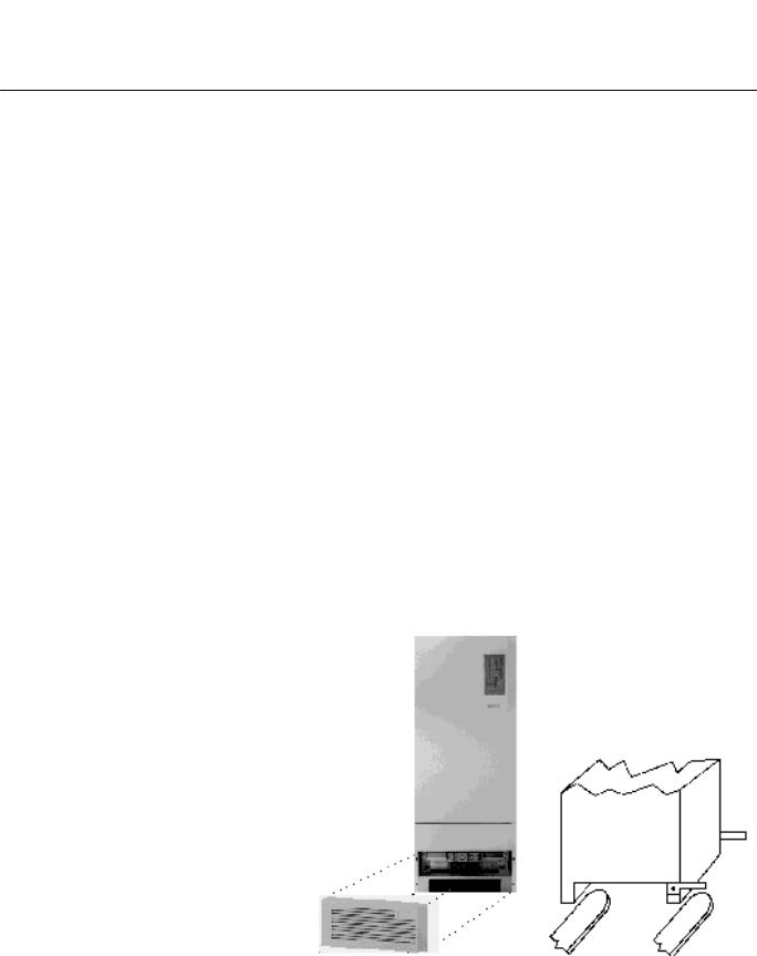
Handling the UPS System The UPS can be simply lifted and moved by means of a lifting truck or a fork lifter for 80-120kVA units. For 10-60kVA units, remove the front side and rear side base sheets and attach two angle irons with 8MA bolts to the right front and rear side of the UPS. The UPS can now be moved with a lifting fork. Remove the angle irons when the UPS is set in the correct position.
Caution: Secure equipment against being knocked over
Setting Up The UPS system should be installed in a dry, clean and lockable room. Provisions have to be made to remove heat created by the system. Under all installation conditions, the unrestricted flow of cooling air must be assured.
JUE 401265

SOLA 4000 - Installation and Initial Start-Up
1 Installation
Weight
Type |
Weight |
Weight |
Static |
|
without |
with |
Load |
||
SOLA |
||||
Battery |
Battery |
- |
||
4000 |
||||
[kg] |
[kg] |
[kg/m²] |
||
|
||||
10 |
310 |
597 |
1277(*) |
|
15 |
310 |
597 |
1277(*) |
|
20 |
335 |
622 |
1330(*) |
|
30 |
350 |
637 |
1362(*) |
|
40 |
480 |
- |
1026 |
|
60 |
520 |
- |
1112 |
|
80 |
810 |
- |
1176 |
|
100 |
840 |
- |
1219 |
|
120 |
870 |
- |
1263 |
|
|
|
|
|
|
TAB. 1.1.1 |
UPS weight |
|
||
Floor Space Required
FIG. 1.1.2 10-60kVA UPS floor space |
FIG. 1.1.3 80-120kVA UPS floor space |
JUE 401265

SOLA 4000 - Installation and Initial Start-Up
1 Installation
Room Size for 10-60 kVA UPS
FIG. 1.1.6 UPS 10-60kVA room size
JUE 401265

SOLA 4000 - Installation and Initial Start-Up
1 Installation
Room Size for 80-120 kVA UPS with auxiliary AC001 cabinet
AC001 cabinets are used for SOLA 4000 units with 12 pulse chargers without galvanic separation and with THD Filters.
FIG. 1.1.7 UPS 80-120kVA room size
JUE 401265

SOLA 4000 - Installation and Initial Start-Up
1 Installation
Room Size for 80-120 kVA UPS with auxiliary AC002 cabinet
AC002 cabinets are used for SOLA 4000 units with 12 pulse chargers with galvanic separation and with auxiliary transformers.
FIG. 1.1.8 UPS 80-120kVA room size
JUE 401265

SOLA 4000 - Installation and Initial Start-Up
1 Installation
1.2 Electrical Installation
This equipment must be installed by qualified service personnel.
Switch off IRP, IRE, IB, IUG, IBY circuit breakers to completely isolate the equipment.
Earth leakage protection: this device has high leakage current towards protective earthing. Earth leakage circuit breakers shouldn't be installed upstream from this equipment or a correct threshold should be set.
High leakage current - it is essential to connect the protective earth before connecting the power supply.
All primary power switches installed remotely from the UPS area must be fitted with the following label: "Isolate uninterruptible power supply (UPS) before working on this circuit".
General
All electrical connections must be made in accordance with local standards and all input terminals (1-L1, 1-L2, 1-L3 and, if existing, 4-L1, 4-L2, 4-L3) must be protected by external fuses. The tables give recommended values for fuse sizes and cable cross-sections. These may vary, depending on local standards. They are valid for voltages 380/220 V, 400/230 V and 415/240 V. Ensure clockwise connection of conductors L1, L2 and L3 at input and output terminals.
If possible, install battery cables separately from other power cables in order to avoid possible RF interference. Before wiring, open all system switches (IRP, IRE, IBY, IUG) plus the battery switch (IB).
JUE 401265
SOLA 4000 - Installation and Initial Start-Up
1 Installation
Version 1 SOLA 4000 with Common Input for Rectifier and Bypass
FIG. 1.2.1 UPS connection diagram, version 1
(*) Note: Internal Battery only for 10-30kVA units
(**) Note: Customer supplied input fuses - see table 1.2.1
JUE 401265

SOLA 4000 - Installation and Initial Start-Up
1 Installation
Version 1 SOLA 4000 with Common Input for
Rectifier and Bypass
Input Cables / Fuses
Type |
|
Input |
Input |
earth |
SOLA |
|
cables |
fuses |
cable |
4000 |
|
[mm²] |
[A] |
[mm²] |
|
|
|
|
|
10 |
|
4x10 |
25 |
16 |
15 |
|
4x10 |
35 |
16 |
20 |
|
4x16 |
50 |
16 |
30 |
|
4x25 |
63 |
25 |
40 |
|
4x35 |
100 |
25 |
60 |
|
4x35 |
125 |
25 |
80 |
|
4x70 |
160 |
50 |
100 |
|
4x70 |
200 |
50 |
120 |
|
4x120 |
250 |
70 |
|
|
|
|
|
TAB.1.2.1 |
UPS input cables |
|
||
and fuses, version 1
Output / Battery Cables and Max. Current Ratings for Battery Overcurr. protection
Type |
Battery |
Output cables |
Max. inv. input |
|
SOLA |
cables |
[mm²] |
current |
|
4000 |
[mm²] |
(Vdc=320V) |
||
|
||||
|
|
|
|
|
10 |
2x16 |
4x10 |
25 |
|
15 |
2x16 |
4x10 |
40 |
|
20 |
2x25 |
4x16 |
50 |
|
30 |
2x25 |
4x35 |
75 |
|
40 |
2x35 |
4x25 |
100 |
|
60 |
2x50 |
4x35 |
150 |
|
80 |
2x70 |
4x50 |
200 |
|
100 |
2x95 |
4x70 |
250 |
|
120 |
2x120 |
4 x120 |
300 |
|
|
|
|
|
TAB.1.2.2 UPS output cables and fuses, version 1
JUE 401265

SOLA 4000 - Installation and Initial Start-Up
1 Installation
Version 2 SOLA 4000 with Separate Inputs for Rectifier and Bypass
FIG. 1.2.2 UPS connection diagram, version 2
(*) Note: Internal Battery only for 10-30kVA units
(**) Note: Customer supplied rectifier input fuses - see table 1.2.5 (***) Note: Customer supplied bypass input fuses - see table 1.2.5
JUE 401265

SOLA 4000 - Installation and Initial Start-Up
1 Installation
Version 2 SOLA 4000 with Separate Inputs for Rectifier and Bypass
Input Cables
|
Type |
|
Rect. |
Bypass |
|
earth |
|
||
|
cables |
|
cables |
|
cable |
|
|||
|
SOLA |
|
|
|
|||||
|
[mm²] |
|
[mm²] |
|
[mm²] |
|
|||
|
4000 |
|
|
|
|||||
|
|
|
|
|
|
|
|
|
|
|
|
|
|
|
|
|
|
|
|
|
10 |
|
3x10 |
|
4x10 |
|
|
16 |
|
|
15 |
|
3x10 |
|
4x10 |
|
|
16 |
|
|
20 |
|
3x16 |
|
4x16 |
|
|
16 |
|
|
30 |
|
3x25 |
|
4x25 |
|
|
25 |
|
|
40 |
|
3x25 |
|
4x25 |
|
|
25 |
|
|
60 |
|
3x35 |
|
4x35 |
|
|
25 |
|
|
80 |
|
3x50 |
|
4x50 |
|
|
50 |
|
|
100 |
|
3x70 |
|
4x70 |
|
|
50 |
|
|
120 |
|
3x120 |
|
4x120 |
|
|
70 |
|
|
|
|
|
|
|
|
|
||
TAB. 1.2.3 UPS input cables, version 2 |
|
||||||||
Input Fuses |
|
|
|
|
|
|
|
|
|
|
|
|
|
|
|
||||
|
Type |
|
Rect. |
Bypass Fuses |
|
||||
|
|
Fuses |
[A] |
|
|
||||
|
SOLA |
|
|
|
|||||
|
|
[A] |
|
|
|
|
|
||
|
4000 |
|
|
|
|
|
|
||
|
|
|
|
|
|
|
|
|
|
|
|
|
|
|
|
|
|
|
|
|
10 |
|
25 |
|
|
25 |
|
|
|
|
15 |
|
35 |
|
|
35 |
|
|
|
|
20 |
|
50 |
|
|
50 |
|
|
|
|
30 |
|
63 |
|
|
63 |
|
|
|
|
40 |
|
100 |
|
100 |
|
|
||
|
60 |
|
100 |
|
125 |
|
|
||
|
80 |
|
125 |
|
160 |
|
|
||
|
100 |
|
160 |
|
200 |
|
|
||
|
120 |
|
200 |
|
250 |
|
|
||
|
|
|
|
|
|||||
TAB. 1.2.4 UPS input fuses, version 2 |
|
||||||||
Output / Battery Cables |
|
|
|
|
|
|
|
|
|
|
|
|
|
|
|
||||
|
Type |
|
Battery |
Output cables |
Max. inv. input |
||||
|
SOLA |
|
cables |
[mm²] |
current |
||||
|
4000 |
|
[mm²] |
(Vdc=320V) |
|||||
|
|
|
|
|
|
||||
|
|
|
|
|
|
|
|||
|
10 |
|
2x16 |
4x10 |
|
25 |
|||
|
15 |
|
2x16 |
4x10 |
|
40 |
|||
|
20 |
|
2x25 |
4x16 |
|
50 |
|||
|
30 |
|
2x25 |
4x35 |
|
75 |
|||
|
40 |
|
2x35 |
4x25 |
|
100 |
|||
|
60 |
|
2x50 |
4x35 |
|
150 |
|||
|
80 |
|
2x70 |
4x50 |
|
200 |
|||
|
100 |
|
2x95 |
4x70 |
|
250 |
|||
|
120 |
|
2x120 |
4 x120 |
300 |
||||
|
|
|
|
|
|
|
|
|
|
TAB. 1.2.5 UPS output cables and fuses, version 2
JUE 401265

SOLA 4000 - Installation and Initial Start-Up
1 Installation
1.3Installation of additional optional cabinets
SOLA 4000 with input and output transformers for voltage adaption
FIG. 1.3.1 UPS connection diagram, with input and output transformers to adapt the
UPS to the on-site voltage.
SOLA 4000 with isolation transformer of the bypass supply
FIG. 1.3.2 UPS connection diagram, with bypass input transformer to isolate the neutral line (** 4-N may be connected to the supply neutral or earth or left disconnected.)
(*) Note: Internal Battery only for 10-30kVA units
JUE 401265

SOLA 4000 - Installation and Initial Start-Up
1 Installation
SOLA 4000 with THD filters
FIG. 1.3.3 UPS connection diagram, with THD filters
(*) Note: Internal Battery only for 10-30kVA units
JUE 401265

SOLA 4000 - Installation and Initial Start-Up
1 Installation
SOLA 4000 with 12-pulse charger / rectifier
FIG. 1.3.4 Installation of 12-pulse units without galvanic isolation
SOLA 4000 with 12-pulse charger / rectifier and galvanic isolation of the input supply.
FIG. 1.3.5 Installation of 12-pulse units with galvanic isolation
(*) Note: Internal Battery only for 10-30kVA units
JUE 401265

SOLA 4000 - Installation and Initial Start-Up
1 Installation
1.4 Installation of an External Maintenance
Bypass
When an external maintenance bypass is installed, a normally open, voltage free contact must be available. This contact must be connected to the connector M4, Pin1 and Pin 2 at the top left hand corner of the mother board for the inverter/bypass electronics (IBYBP-CP see figure 1.10.3).
If the standard SOLA no-break wall-mounted maintenance bypass switch is used (optional) in the MB3 cabinet, a normally open contact is provided.For the version 2 maintenance bypass (3 position), an additional contact is provided which automatically isolates the UPS system (EPO) when switched to the "UPS ISOLATED" position (see FIG 1.4.2).
FIG.1.4.1 External Maintenance Bypass Switch Version 1 (2 position)
JUE 401265

SOLA 4000 - Installation and Initial Start-Up
1 Installation
FIG.1.4.2 External Maintenance Bypass Switch Version 2 (3 position)
Note1: For Hot-Standby or parallel systems, it is sufficient to feed one contact into one unit only, however they may be
connected in parallel at M4 (of IBYBP-CP) Pin1 and Pin 2 for all units. In this case separate terminals may be provided within the MB3 cabinet (see FIG. 1.9.2 and 1.10.2)
Note2: The cable used must be twisted pair, with a total shield.
This shield must be grounded at one end (the cabinet of the
UPS may be used).
JUE 401265

SOLA 4000 - Installation and Initial Start-Up
1 Installation
1.5 CPNET Interface Card
The CPNET interface card is used for remote signalling of four standard alarm conditions by means of voltage-free contacts in programmable configurations.
1.5.1 Installation
The CPNET interface card is a small pcb that is installed directly underneath the CPU/NCP pcb, inside the front door of the UPS cabinet.
It is connected to the UPS via the connector CN1 on the CPNET pcb to CN10 on the CPU/NCP pcb.
It can be connected to remote devices via two different connectors:
•CN2, a 9 pin sub-D connector for standard computer connection. The following interface cables are available (see also JUE 300 599):
-IBM AS-400
-Novell
-3-COM
-Banyan Vines
•M1, a terminal block for individual configurations.
1.5.2 Functions
Contacts for the following alarm conditions are available:
Inverter Operation (N) |
(CN1, pin 6) |
Bypass Operation (B) |
(CN1, pin 8) |
Mains Failure (MF) |
(CN1, pin 5) |
Battery Low (BL) |
(CN1, pin 7) |
By means of the DIP switch SW1, the single relays and output pins can be configured for each requirement.
|
|
|
|
SW1 |
|
|
|
INTERFACE |
|
1 |
2 |
3 |
4 |
5 |
6 |
7 |
8 |
||
|
|||||||||
|
|
|
|
|
|
|
|
|
|
0 |
0 |
0 |
1 |
0 |
1 |
1 |
0 |
IBM-AS400 |
|
0 |
0 |
0 |
0 |
- |
- |
0 |
1 |
NOVEL |
|
0 |
0 |
1 |
0 |
- |
- |
- |
- |
3-COM |
|
0 |
0 |
0 |
0 |
- |
- |
- |
- |
BANYAN-VINES |
|
0 |
1 |
1 |
0 |
- |
- |
0 |
1 |
BORRI VIKING |
|
0 |
0 |
1 |
0 |
- |
- |
0 |
1 |
BORRI SIDEKICK |
|
0 |
0 |
1 |
0 |
- |
- |
0 |
1 |
AMERICAN POWER |
|
|
|
|
|
|
|
|
|
|
TAB. 1.5.2.1 Programming of the CP-NET pcb
Note: Maximum rating of relay contacts: 250Vac, 6A (only when using connector M1)
JUE 401265
 Loading...