


PM0606750
Insert
Additif
Adición
ELECTRIC GENERATOR - GROUPE ELECTROGENE - GENERADOR ELECTRICO
Thank you for selecting a Coleman® Powermate® Generator. The Coleman® Powermate® generator has been made to supply reliable, portable electrical power when utility power is not available. We hope you will enjoy your new generator. Welcome to our worldwide family of Coleman® Powermate® generator users.
Merci d'avoir choisi le groupe électrogène Coleman® Powermate®. Ce groupe électrogène Coleman® Powermate® a été conçu pour fournir le pouvoir électrique, portatif et fiable quand le pouvoir d'utilité n'est pas disponible. Nous espérons que votre groupe électrogène vous donnera entière satisfaction. Bienvenue dans la famille mondiale des utilisateurs de groupes électrogènes Coleman® Powermate®.
Gracias por seleccionar un generador Coleman® Powermate®. El generador Coleman® Powermate® ha sido diseñado para proporcionar energía eléctrica confiable y portátil cuando no hay servicio disponible de energía pública. Esperamos que disfrute de su nuevo generador. Bienvenido a nuestra familia de usuarios de generadores Coleman® Powermate® a nivel mundial.
IMPORTANT – Please make certain that persons who are to use this equipment thoroughly read and understand these instructions and any additional instructions provided prior to operation.
IMPORTANT - Prière de vous assurer que les personnes destinées à utiliser cet appareil ont pris soin d'en lire et d'en comprendre le mode d'emploi ou les directives avant de le mettre en marche.
IMPORTANTE. Asegúrese que las personas que utilizarán este equipo lean y entiendan completamente estas instrucciones y cualquier instrucción adicional proporcionada antes del funcionamiento.
|
|
www.powermate.com |
04/06 0063820 |
MAJOR GENERATOR FEATURES
*12 HP Yamaha OHV engine
*Cast-iron cylinder sleeve
*Low oil sensor
*Receptacles on control panel
*DIGITECH™ Digital Information Center
*7 gallon metal fuel tank
*Portability Kit
CONTROL PANEL
A.120 Volt GFCI Receptacle
Ground Fault Circuit Interrupter duplex receptacle is rated so that a total of 20 amps may be drawn regardless of whether both halves or just one receptacle is used. This receptacle may be used along with other receptacles provided the generator is not overloaded and total power drawn is kept within nameplate ratings.
Ground Fault Circuit Interrupter
(Conforms to U.L 943, Class A and NEC requirements) This device protects you against hazardous electrical shock
that may be caused if your body becomes a path through which electricity travels to reach ground. This could happen when you touch an appliance or cord that is “ live “ through faulty mechanism, damp or worn insulation, etc.
B.120/240 V, 30 Ampere Twistlock Receptacle
A maximum of 30 amps may be drawn from the 120/240
volt receptacle, provided it is the only receptacle used. However, current must be limited to the nameplate rating. If the 120/240 volt receptacle is used along with the 120 volt receptacle, the total load drawn must not exceed the nameplate ratings.
C.Circuit Breakers
The receptacles are protected by an AC circuit breaker. If
the generator is overloaded or an external short circuit occurs, the circuit breaker will trip. If this occurs, disconnect all electrical loads and try to determine the cause of the problem before attempting to use the generator again. If overloading causes the circuit breaker to trip, reduce the load. NOTE:
Continuous tripping of the circuit breaker may cause damage to generator or equipment. The circuit breaker may be reset by pushing the button of the breaker.
D.Engine On/Off Switch
E.DIGITECH™ Digital Information Center
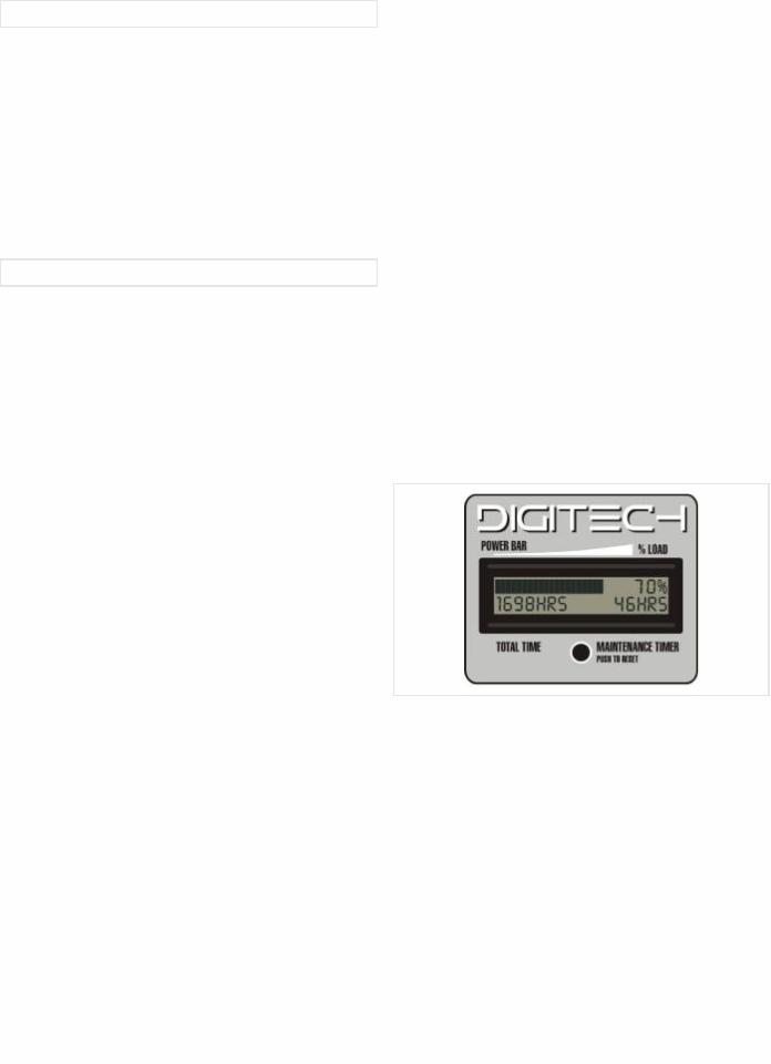
The DIGITECH™ Digital Information Center is a patented feature available only on select Coleman® Powermate® Brand generators.
At a glance, the user can instantly see how much of the generator's output capacity is being used and how much power remains available. The display also indicates the time since last user reset and the total accumulated runtime of the generator.
Power Bar - This bargraph provides a quick visual indication of the percentage of rated output currently being supplied.
% Load Indicator - This is a numeric version of the Power Bar.
Total Timer - This indicates the total number of hours the generator has run since manufacture.
Maintenance Timer - This indicates the number of hours the generator has run since the last user reset. This timer should be reset after every oil change or any other maintenance task. Follow the instructions in the engine owners manual for proper engine maintenance intervals.
Reset Button - Pressing and holding this button will reset the Maintenance Timer to 0 HRS.
|
|
|
|
|
|
|
|
English |
|
2 |
||||
|
|
|

PORTABILITY KIT INSTALLATION
TOOLS REQUIRED: 1/2” and 9/16" sockets and ratchets, block(s) of wood (minimum of 6” tall). Refer to the parts list on page 9.
WHEEL INSTALLATION
1.Block up end of generator opposite the fuel tank cap to install wheel kit.
2.Insert wheel spacer (item 39) into the center of the wheel
(item 28).
3.Slide 3/8 x 4.25” bolt (item 32) and 3/8 washer (item 27) through the wheel (item 28), then through the wheel bracket on the carrier, with the offset side of the wheel hub against the wheel bracket.
4.Thread 3/8 nyloc nut (item 33) onto the bolt and tighten to securely clamp the wheel assembly to the carrier.
5.Repeat above instructions for the remaining wheel.
FOOT INSTALLATION
1.Blocking up the engine side of the generator, place the foot bracket (item 43) under the carrier channel. Thread a 5/16-18 x 4” bolt (item 42) with a rubber foot (item 29) through the mounting holes and thread a 5/16 flange nut (item 47) to the bolt to secure the foot bracket to the carrier.
Caution: Do not over tighten so that the rubber foot material collapses.
LOCKING HANDLE
1.Attach the lanyards (item 30) to the release pins (item 34) and carrier as shown in the illustration.
2.To lock the handle (item 25) in the extended position, align the holes in the handle brackets with the holes in the carrier brackets and insert the release pins (item 34).
1 |
|
|
|
|
|
2 |
|
|
|
|
|
|
|
|
|
|
|
|
|
|
|
|
|
|
|
|
|
|
|
|
|
|
|
|
30 |
34 |
LIMITED WARRANTY
Warranty Coverage: Powermate Corporation (the Company) warrants to the original retail customer in North America that it will repair or replace, free of charge, any parts found by the Company or its authorized service representative to be defective in material or workmanship. This warranty covers the cost of replacement parts and labor for defects in material or workmanship.
Not Covered:
·Transportation charges for sending the product to the Company or its authorized service representative for warranty service, or for shipping repaired or replacement products back to the customer; these charges must be borne by the customer.
·Engine is covered exclusively by a separate warranty from the engine manufacturer, included with the engine Manual.
·Damages caused by abuse or accident, and the effects of corrosion, erosion and normal wear and tear.
·Warranty is voided if the customer fails to install, maintain and operate the product in accordance with the instructions and recommendations of the Company set forth in the owner's manual.
·The Company will not pay for repairs or adjustments to the product, or for any costs or labor, performed without the Company's prior authorization.
Warranty Period: Two (2) years from the date of purchase on products used solely for consumer applications; if a product is used for business or commercial applications, the warranty period will be limited to one (1) year from the date of purchase; if a product is used for rental applications, the warranty period will be limited to ninety (90) days from the date of purchase. For warranty service, the customer must provide dated proof of purchase and must notify the Company within the warranty period.
For warranty service: Call toll free 800-445-1805, or write to Powermate Corporation, Product Services, 4970 Airport Road, P. O. Box 6001, Kearney, NE 68848.
EXCLUSIONS AND LIMITATIONS: THE COMPANY MAKES NO OTHER WARRANTY OF ANY KIND, EXPRESS OR IMPLIED. IMPLIED WARRANTIES, INCLUDING WARRANTIES OF MERCHANTABILITY AND OF FITNESS FOR A PARTICULAR PURPOSE, ARE HEREBY DISCLAIMED. THE WARRANTY SERVICE DESCRIBED ABOVE IS THE EXCLUSIVE REMEDY UNDER THIS WARRANTY; LIABILITY FOR INCIDENTAL AND CONSEQUENTIAL DAMAGES IS EXCLUDED TO THE EXTENT PERMITTED BY LAW.
This warranty gives you specific legal rights, and you may also have other rights which vary from state to state. Some states do not allow a disclaimer of implied warranties, or the exclusion or limitation of incidental and consequential damages, so the above disclaimers and exclusions may not apply to you.
|
|
|
English |
3 |
|
|
|
|
CARACTÉRISTIQUES PRINCIPALES DU
GROUPE ELECTROGENE
*Moteur 12 HP Yamaha OHV
*Chemise de cylindres en fonte
*Détecteur de bas niveau d'huile
*Prises sur tableau de commande
*Le centre d'information numérique DIGITECH™
*Réservoir de carburant en métal d'une contenance de 26.5 litres (7 gallons)
*Kit de transport
TABLEAU DE COMMANDE
A.Boîtier k’interrupteur de circuit en cas de fuite à la terre 120 volts.
Le boîtier de prise double d’interrupteur de circuit en cas de fuite à la terre a une valeur nominale telle qu’un total de 20
Apeut être tiré indépendemment du boîtier utilisé (simple ou demi). Ce boîtier puet être utilisé avec les autres boîtiers en autant que le générateur n’est pas surchargé et que la puisance totale reste dans la fourchette de valeurs indiquées sur la plaque signalétique.
Interrupteur de circuit en cas de fuite à la terre
(conforme à U.L. 943, Catégorie A et ixigences NEC). Cet appareil vous protège contre les dangers de chocs
électriques qui peuvent ítre causés si votre corps devient un conduit pour l’électricité se rendant à la terre. Ceci peut se produire si vous touchez u appareil ou un cordon qui est “sous tension” suite à un mécanisme défectueux, un isolant usé ou humide etc.
B.Prise à verrouillage de 120/240 V, 30 A
Cette prise de 120/240 V fournit un maximum de 30 A à
condition que ce soit la seule utilisée. La charge totale doit par ailleurs rester dans les limites indiquées sur la plaque signalétique. Si la prise de 120/240 V est utilisée en conjonction avec les prises de 120 V, la charge totale ne doit pas dépasser les limites indiquées sur la plaque.
C.Disjoncteurs
Les prises sont protégées par un disjoncteur alternatif. En
cas de surcharge ou de court-circuit extérieur, le disjoncteur saute. Si cela se produit, débrancher tout appareil relié au groupe électrogène et essayer de déterminer la cause du
problème avant d’essayer de le réutiliser. Si le disjoncteur saute en raison d’une surcharge, réduire la charge.
REMARQUE : Le groupe électrogène ou les appareils branchés dessus peuvent se trouver abîmés si le disjoncteur saute continuellement. Appuyer sur le bouton du disjoncteur pour le réenclencher.
D.Commutateur On/Off (Sur/De) du moteur
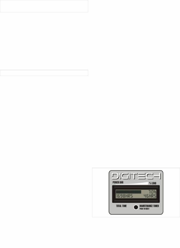
E.Le centre d'information numérique DIGITECH™
Le centre d'information numérique DIGITECH™ est une caractéristique brevetée disponible seulement sur certains modèles de génératrice Powermate sélectionnés.
D'un coup d'œil, l'utilisateur put immédiatement voir la puissance nette utilisée par la génératrice et l'alimentation toujours disponible. L'affichage indique également quand s'est faite la dernière réinitialisation et le temps de marche total accumulé par la génératrice.
Plaque multiprises (POWER BAR) - Cet indicateur statique à colonnes donne un aperçu du pourcentage fourni de puissance nominale.
Témoin de charge en pourcentage (% LOAD) - Il s'agit d'une version numérique de la plaque multiprises.
Indicateur de durée totale (TOTAL TIME) - Il indique le nombre total d'heures au cours desquelles la génératrice a été en marche depuis sa fabrication.
Indicateur de durée de maintenance (MAINTENANCE TIMER) - Il indique le nombre d'heures au cours desquelles la génératrice a été en marche depuis la dernière réinitialisation par l'utilisateur. Cet indicateur doit être réinitialisé après chaque changement d'huile ou après tous travaux de maintenance. Suivez les directives contenues dans le manuel du propriétaire du moteur pour connaître les périodes appropriées d'entretien du moteur.
Bouton de réinitialisation (PUSH TO RESET) - Lorsque vous appuyez sur ce bouton, l'indicateur de durée de maintenance est mis à 0 HR.
4 |
|
|
|
|
Français |
||
|
|
|
|
 Loading...