


Powerex SES02, SE12, SES03, SES13, SES05 User Manual
...2 HP - 5 HP Scroll Enclosure Air Compressors
Please read and save these instructions. Read carefully before attempting to assemble, install, operate or maintain the product described. Protect yourself and others by observing all safety information. Failure to comply with instructions could result in personal injury and/or property damage! Retain instructions for future reference.
Description
GENERAL
The Powerex Oilless Rotary Scroll Air Compressor has advanced scroll compressor technology through the development of a completely oilless compressor. The Powerex Scroll Compressor offers a dynamically balanced air end which insures vibrationfree operation. The rotary design permits a continuous 100% duty cycle.
Other standard features on the Powerex Scroll Compressor include: a Magnetic Starter, Motor Overload Protection, a High Temperature Shutdown Switch, an Air Cooled Aftercooler and a Single Phase or Three Phase 4 Pole ODP motor.
:$51,1* |
35(9(17 |
Safety Guidelines
A SEPARATE SAFETY BOOKLET IS PROVIDED ALONG WITH THIS MANUAL. READ AND UNDERSTAND The SAFETY BOOKLET. This manual contains information that is very important to know and understand. This information is provided for SAFETY and to PREVENT EQUIPMENT PROBLEMS. To help recognize this information, observe the following symbols. MAKE SURE EVRYONE OPERATING OR SERVICING THE COMPRESSOR READS AND UNDERSTANDS ALL The INFORMATION PROVIDED.
Danger indicates an imminently hazardous situation which, if not avoided,
WILL result in death or serious injury.
Warning indicates a potentially hazardous situation which, if not avoided,
COULD result in death or serious injury.
Caution indicates a potentially minor or moderate injury.
Installation
INSTALLATION SITE
1. The scroll compressor must be located in a clean, well lit and well ventilated area.
2.The area should be free of excessive dust, toxic or flammable gases, moisture, water, and direct sunlight.
3.Never install the compressor where the ambient temperature is higher than 104o F or where humidity is high.
4.Clearance must allow for safe, effective inspection and maintenance. 20 inches of clearance for sides is recommended.
Specifications
Product |
|
SES Series Powerex Simplex Air Compressors |
|||
|
|
|
|
|
|
Performance |
|
See Page 2 |
|
|
|
Specifications |
|
|
|
|
|
|
|
|
|
||
Lubrication |
|
Grease-filled Bearing |
|||
|
|
|
|
|
|
Operating |
1Ø |
230 Volts, 60 Hz; 230 Volts, 50 Hz |
|||
Voltages |
|
3Ø |
208-230/460/575 Volts, 60 Hz |
|
|
|
|
|
|
|
|
Compression Cycle |
|
Scroll |
|
|
|
|
|
|
|
||
Motor Overload |
|
IEC Motor Overload Relay |
|||
Protection |
|
|
|
|
|
|
|
|
|
|
|
Pressure Settings |
|
Cut-In: 95 psig |
Cut-Out: 115 psig |
||
|
|
Cut-In: 115 psig |
Cut-Out: 145 psig |
|
|
|
|
|
|
(High Pressure Unit) |
|
|
|
|
|
||
Overpressure |
|
ASME Safety Valve Factory Set and Sealed |
|||
Protection |
|
|
|
|
|
|
|
|
|
|
|
Outlet Air |
|
3/8 inch NPT |
|
|
|
Connections |
|
|
|
|
|
|
|
|
|
||
Tank Size |
|
13 Gallon ASME Rated 175 psig |
|||
|
|
|
|
||
California Ordinance |
|
Meets Requirements of this Ordinance |
|||
462 (L) (2) |
|
|
|
|
|
|
|
|
|
||
Tank Isolation |
|
Standard All Units |
|||
|
|
|
|
|
|
Drive |
|
3V Belt |
|
|
|
|
|
|
|
|
|
Control Panel |
|
UL508A Listed |
|
|
|
|
|
|
|
|
|
Powerex • 150 Production Drive • Harrison, OH 45030 • USA |
IN188614AV 1/14 |
1-888-769-7979 • www.powerexinc.com |
|

2 HP - 5 HP Scroll Enclosure Air Compressors
Compressor Specifications
Model |
SES02 |
|
SES12 |
SES03 |
|
SES13 |
SES05 |
|
SES15 |
|
|
|
|
|
|
|
|
|
|
HP |
2 |
|
3 |
|
5 |
|
|||
|
|
|
|
|
|
|
|
|
|
Phase |
3Ø |
|
1Ø |
3Ø |
|
1Ø |
3Ø |
|
1Ø |
|
|
|
|
|
|
|
|
|
|
Voltage |
208 - 230 / 460 / 575 |
|
230 |
208 - 230 / 460 / 575 |
|
230 |
208 - 230 / 460 / 575 |
|
230 |
|
|
|
|
|
|
|
|
|
|
Amps |
|
|
|
See wiring diagram for amp rating |
|
|
|
||
|
|
|
|
|
|
||||
Air End |
SLAE03EB |
|
SLAE03EB |
|
SLAE05E (SLAE05EHP) |
||||
|
|
|
|
||||||
Control System |
Pressure Switch |
Pressure Switch |
Pressure Switch |
||||||
|
|
|
|
||||||
Discharge Pressure (PSIG) |
95 - 115 (115 - 145 optional) |
95 - 115 (115 - 145 optional) |
95 - 115 (115 - 145 optional) |
||||||
|
|
|
|
||||||
Air Delivery (CFM) |
6.0 @ 100 PSIG and (4.6 @ 145 PSIG) |
8.8 @ 100 PSIG and (7.1 @ 145 PSIG) |
15.2 @ 100 PSIG and (12.5 @ 145 PSIG) |
||||||
|
|
|
|
|
|
|
|||
Compressor Speed (RPM) |
2200 (1850) |
|
3140 (2770) |
|
3250 (3250) |
|
|||
|
|
|
|
||||||
Discharge Temp. |
Ambient temp. + 30 °F |
Ambient temp. + 30 °F |
Ambient temp. + 30 °F |
||||||
|
|
|
|
|
|
|
|
|
|
Noise level dB(A) |
49 |
|
49 |
|
51 |
|
|||
[1.5m from front] |
|
|
|
||||||
|
|
|
|
|
|
|
|
|
|
|
|
|
|
|
|
|
|||
Dimensions In Inches (L x W x H) |
34 x 21 x 32.5 |
|
34 x 21 x 32.5 |
|
34 x 21 x 32.5 |
|
|||
|
|
|
|
|
|
|
|
|
|
|
(Items in paranthesis high pressure information) |
|
|
|
|
||||
|
|
|
|
|
|
|
|
|
|
Installation (Continued)
5.If necessary, use metal shims or leveling pads to level the compressor. Never use wood to shim the compressor.
6.Never install the compressor outside.
7.For 3 and 5 HP single phase models it is recommended that additional tank volume be added. 3 HP single phase models need a minimum of 30 gallons air capacity to limit the number of starts-per-hour to 14 maximum. 5 HP single phase models need a minimum of 60 gallons air capacity to limit the number of starts-per-hour to 10 maximum.
VENTILATION
1.If the scroll compressor is located in a totally enclosed room, an exhaust fan with access to outside air must be installed.
2.Never restrict the cooling fan exhaust air.
3.Vent the exhaust air outside to prevent the compressor from operating at high temperatures and shutting down.
4.Never locate the compressor where hot exhaust air from other heat generating units may be pulled into the unit.
WIRING
All electrical connections must be performed by a qualified electrician. Installations must be in accordance with local and national electrical codes.
1.Make sure power source is the same voltage as the unit’s required voltage
2.Use solderless terminals to connect the electric power source.
3.Remove the two left panels.
4.Pull the electric cable through the electric source inlet and connect to the primary side of the contact blocks.
5.Since loosening of wires is possible in shipment, tighten all wire terminals prior to starting the unit.
PIPING
General Guidelines
1.Make sure the piping is lined up without being strained or twisted when assembling the piping for the scroll compressor.
2.Appropriate expansion loops or bends should be installed at the compressor to avoid stresses caused by changes in
hot and cold conditions.
3.Piping supports should be anchored separately from the compressor to reduce noise and vibration.
4.Never use any piping smaller than the compressor connection.
5.Use flexible hose to connect the outlet of the compressor to the piping so that the vibration of the compressor does not transfer to the piping.
Remote Intake Piping
Powerex Compressor Systems with pipe thread connectors on the intake filters are intended for installation with remote air intake. Piping for the remote intake system must be installed at the final operating site.
Under some conditions, the intake piping may facilitate the condensation of humidity in the intake air stream into liquid water.
The intake filters supplied by Powerex will not stop ingestion
of liquid water by the pumps. Liquid water going into the pumps will damage the pumps and void the warranty.
Always install drip legs with sufficient capacity to capture liquid water in the intake piping before the air filters. Drip legs must be sized with low enough air velocity to make sure they are effective at capturing liquid water in the intake air and must be maintained (drained) at frequent intervals to make sure they remain effective.
SAFETY VALVES
Tank mounted compressors are shipped from the factory with safety valves installed in the air receiver manifold. The flow capacity of the safety valve is equal to or greater than the capacity of the compressor.
1.The pressure setting of the safety valve must be equal or less than the maximum working pressure of the air receiver.
2.Safety valves should be placed ahead of any possible blockage point in the system, i.e. shutoff valve.
3.Avoid connecting the safety valve with any tubing or piping.
4.Manually operate the safety valve every six months to avoid sticking or freezing.
2
2 HP - 5 HP Scroll Enclosure Air Compressors
Operation
BEFORE START UP
1.Make sure all safety warnings, labels and instructions have been read and understood before continuing.
2.Remove any shipping materials, brackets, etc.
3.Confirm that the electric power source and ground have been firmly connected.
4.Check the belts for tightness.
5.Be sure all pressure connections are tight.
6.Check to be certain all safety relief valves, etc., are correctly installed.
7.Securely mount all panels and guards.
8.Check that all fuses, circuit breakers, etc., are the proper size.
9.Make sure the inlet filter is properly installed.
10.Confirm that the drain valve is closed.
START-UP AND OPERATION
1.Visually check the rotation of the compressor pump. The rotation should be counterclockwise if viewing the
compressor from the belt side. If the rotation is incorrect, have a qualified electrician correct the supply wiring.
2.Follow all the procedures under “Before start-up” before attempting operation of the compressor.
3.Make sure compressor switch is in the OFF position.
4.Switch the electric source breaker on.
5.Open the 3/8 inch discharge valve completely.
6.Turn compressor switch to ON position and check that the compressor operates without excessive vibration, unusual noises or leaks.
7.Close the discharge valve completely.
8.If the pressure does not rise on a three phase unit, turn the unit off. Have a qualified electrician switch the breaker OFF and exchange the L1 and L2 connections (two out of three phases of electric source) on the control panel.
9.Check the discharge pressure. Also make sure the air pressure rises to the designated pressure setting by checking the discharge pressure gauge.
10.Check the operation of the pressure switch by opening the outlet valve and confirming the compressor starts at approximately 95 psig for low pressure units and 115 psig or high pressure units.
DAILY OPERATION
1.Stop the compressor by turning switch to the OFF position.
NOTE: If the compressor rotates in reverse for more than five seconds, the check valve needs to be cleaned or replaced.
2.Switch the breaker OFF if the compressor is not to be used for a long period of time.
STOPPING THE COMPRESSOR DURING
NORMAL OPERATION
1.Close the discharge valve.
2.Allow the air pressure to build and the compressor to stop.
3.Turn the compressor off by turning switch to the OFF position.
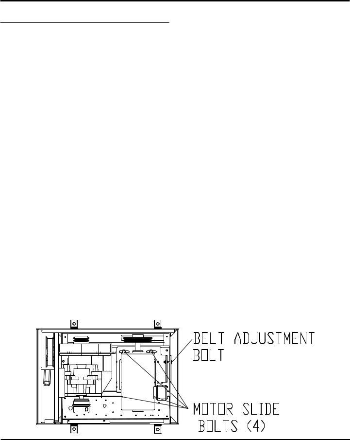
BELT ADJUSTMENT PROCEDURE
1.Remove the top panel by removing the two slotted 1/4-20 screws on the rear of the enclosure.
2.Loosen the four (4) motor slide bolts.
3.Tighten belt by adjusting the belt adjustment bolt. Belt tension for new belts should be 57 to 65 lbs for the loosest belt in the set, then 45-50 lbs after run-in. If the belt tension falls below 25 lbs or chirping is heard as start up, re-tension belts. (If using the deflection method for belt tension, 3.8-4.3 lbs force at mid span should give 7/32 inch belt deflection for a new belt, 3.0-3.38 for a used belt for 7/32 inch belt deflection.
4.Tighten the four (4) motor slide bolts. Tighten the two electrical panel side slide bolts first then tighten the two pulley side slide bolts.
Figure 1
3

2 HP - 5 HP Scroll Enclosure Air Compressors
Scroll Unit Parts Breakdown -
Models SES02, SES12, SES03, SES13, SES05, SES15, SF120_PHA, and SF130_PHA |
|
|
|
|
|
||||||||||||
15 |
18 |
|
|
|
5 |
14 |
13 |
|
|
2 |
8 |
|
|
|
|
|
|
|
|
|
|
|
|
|
|
|
|
|
|
|
|
|
|
22 |
|
49 |
|
|
|
|
|
|
|
|
|
|
|
|
|
|
|
3 |
|
|
|
|
|
|
|
|
|
|
|
|
|
|
|
|
|
|
|
38 |
|
|
|
|
|
|
|
|
|
|
|
|
|
|
|
|
|
37 |
|
|
|
|
|
|
|
|
|
|
|
|
|
|
|
|
|
|
|
|
|
|
|
|
|
|
|
|
|
23.15 |
|
|
|
20 |
|
|
|
|
|
|
|
|
|
|
|
|
|
|
|
|
|
|
|
51 |
|
|
|
|
|
|
|
|
|
|
|
|
|
|
|
|
|
50 |
|
|
|
|
|
|
|
|
|
|
|
|
|
|
|
|
|
17 |
|
|
|
|
|
|
|
|
|
|
|
|
|
|
|
21 |
|
16 |
|
|
|
|
|
|
|
|
|
|
|
|
|
|
|
26 |
|
30 |
|
|
|
|
|
|
|
|
|
|
|
|
|
|
|
25 |
|
|
|
|
|
|
|
|
|
|
|
|
|
|
|
|
|
|
|
10 |
|
|
|
|
|
|
|
|
|
|
|
|
|
|
|
|
|
52 |
|
|
|
|
|
|
|
|
|
|
|
|
|
|
|
|
|
11 28 |
|
|
|
|
|
|
|
|
|
|
|
|
|
|
|
|
|
43 |
|
|
|
|
|
|
|
|
|
|
|
|
|
|
|
34 |
|
|
|
|
|
|
|
|
|
|
|
|
|
|
|
|
33 |
|
|
42 |
|
|
|
|
|
|
|
|
|
|
|
|
|
|
|
|
|
41 |
|
|
|
|
|
|
|
|
|
|
|
|
|
|
|
32 |
|
31 |
|
|
|
|
|
|
|
|
|
|
|
|
|
|
|
|
|
4 |
|
|
|
|
|
|
|
|
|
|
|
|
|
|
|
|
|
35 |
|
|
|
|
|
|
|
|
|
|
|
|
|
|
|
27 |
|
|
|
|
|
|
|
|
|
|
|
|
|
|
|
|
|
|
|
|
|
|
|
|
|
|
|
|
|
|
|
|
|
|
|
8 |
|
7 |
|
|
|
|
|
|
|
|
|
|
|
|
|
|
|
|
|
40 |
|
|
|
|
|
|
|
|
|
|
|
20.00 |
0.50 |
|
|
|
|
29 |
|
|
|
|
|
|
|
|
|
|
|
|
DIA |
|
|
|
|
|
|
|
|
|
|
|
|
|
|
|
|
|
4 X |
|
|
|
|
|
|
|
|
|
|
|
|
|
|
|
|
|
|
|
|
39 |
|
12 1 |
|
19 |
|
|
23 |
24 |
|
19 |
|
|
|
1/4 INCH FNPT |
TANK DRAIN |
3/8 INCH FNPT |
AIR OUTLET |
MAIN POWER |
INLET |
6 |
9 |
45 |
44 |
47 |
53 |
46 |
54 |
36 |
|
|
|
|
|
||||
Figure 2 |
|
|
|
|
|
|
|
|
|
|
|
|
|
|
|
|
|
|
|
|
|
|
|
4 |
|
|
|
|
|
|
|
|
|
|
|

2 HP - 5 HP Scroll Enclosure Air Compressors
Ref. No. |
Description |
SES02 / SES12 |
SES03 / SES13 |
SES05 / SES15 |
Qty. |
1 |
Air end |
|
|
|
|
|
(low pressure) |
SL014003AJ |
SL014003AJ |
SL016502AJ |
1 |
|
(high pressure) |
SL014003AJ |
SL014003AJ |
SL016511AJ |
1 |
2 |
13 gallon tank |
AR234800WH |
AR234800WH |
AR234800WH |
1 |
3 |
Unit base |
SL303600AV |
SL303600AV |
SL303600AV |
1 |
4 |
Front panel |
SL304500AV |
SL304500AV |
SL304500AV |
1 |
5 |
Right panel |
SL304400AV |
SL304400AV |
SL304400AV |
1 |
6 |
Back panel |
SL304600AV |
SL304600AV |
SL304600AV |
1 |
7 |
Top panel |
SL304800AV |
SL304800AV |
SL304800AV |
1 |
8 |
Utility panel |
SL305200AV |
SL305200AV |
SL305200AV |
3 |
9 |
Internal duct |
SL304901AV |
SL304901AV |
SL304901AV |
1 |
10 |
Left panel |
SL304300AV |
SL304300AV |
SL304300AV |
1 |
11 |
Maintenance panel 1 |
SL305000AV |
SL305000AV |
SL305000AV |
1 |
12 |
Inside panel |
SL304700AV |
SL304700AV |
SL304700AV |
1 |
13 |
Pump base |
SL304101AV |
SL304101AV |
SL304101AV |
1 |
14 |
Mounting foot |
IP630300AV |
IP630300AV |
IP630300AV |
4 |
15 |
“H” support |
SL305100AV |
SL305100AV |
SL305100AV |
2 |
16 |
Inlet filter assembly |
ST073925AV |
ST073925AV |
ST073925AV |
1 |
17 |
Filter element |
ST073921AV |
ST073921AV |
ST073921AV |
1 |
18 |
Motor pulley |
|
|
|
|
|
2HP (low pressure, 2-3V4.45) |
3Ø PU202633AV |
- |
- |
1 |
|
|
1Ø PU202623AV |
|
|
|
|
2HP (high pressure, 2-3V3.65) |
3Ø PU202632AV |
- |
- |
1 |
|
|
1Ø PU202622AV |
|
|
|
|
3HP (low pressure, 2-3V6.0) |
- |
PU202625AV |
- |
1 |
|
3HP (high pressure, 2-3V5.3) |
- |
PU202624AV |
- |
1 |
|
5HP (low pressure, 2-3V6.9) |
- |
- |
PU009754AV |
1 |
|
5HP (high pressure, 2-3V6.9) |
- |
- |
PU009754AV |
1 |
20 |
1/4 T x 1/4 P x 90˚ push connect |
ST119702AV |
ST119702AV |
ST119702AV |
1 |
21 |
1/4 inch drain tube |
PS010300AV |
PS010300AV |
PS010300AV |
2.0 ft. |
22 |
Corner angle |
ST185500AV |
ST185500AV |
ST185500AV |
4 |
23 |
Temperature switch @ 115 psi |
AM003011AV |
AM003011AV |
AM003011AV |
1 |
|
Temperature switch @ 145 psi |
AM003012AV |
AM003012AV |
AM003012AV |
1 |
24 |
Sub panel |
SL305300AV |
SL305300AV |
SL305300AV |
1 |
25 |
1/4 inch bulk head fitting |
PS006701AV |
PS006701AV |
PS006701AV |
1 |
26 |
3/8 inch bulk head fitting |
PS006702AV |
PS006702AV |
PS006702AV |
1 |
27 |
Safety valve |
|
|
|
|
|
(Low pressure unit) |
V-215100AV |
V-215100AV |
V-215100AV |
1 |
|
(High pressure unit) |
V-215401AV |
V-215401AV |
V-215401AV |
1 |
28 |
Maintenance panel 2 |
SL306500AV |
SL306500AV |
SL306500AV |
1 |
29 |
Motor slide base |
SL306701AV |
SL306701AV |
SL306701AV |
1 |
30 |
Pressure switch |
|
|
|
|
|
(Low pressure unit) |
CW207573AV |
CW207573AV |
CW207573AV |
1 |
|
(High pressure unit) |
CW207595AV |
CW207595AV |
CW207595AV |
1 |
31 |
Lighted off/on switch |
PE000560AV |
PE000560AV |
PE000560AV |
1 |
32 |
3/8 inch ball valve |
ST079802AV |
ST079802AV |
ST079802AV |
1 |
33 |
1/4 inch ball valve |
ST079806AV |
ST079806AV |
ST079806AV |
1 |
34 |
Electrical strain relief |
ST188106AV |
ST188106AV |
ST188106AV |
1 |
35 |
Motor |
|
|
|
|
|
2hp 1 phase |
MC301579AV |
- |
- |
1 |
|
2hp 3 phase |
MC303300AV |
- |
- |
1 |
|
3hp 1 phase |
- |
MC301579AV |
- |
1 |
|
3hp 3 phase (208 - 230 / 460 V) |
- |
MC303301AV |
- |
1 |
|
3hp 3 phase (575 V) |
- |
MC303302AV |
- |
1 |
|
5hp 1 phase |
- |
- |
MC022393AV |
1 |
|
5hp 3 phase (208 - 230 / 460 V) |
- |
- |
MC303303AV |
1 |
|
5hp 3 phase (575 V) |
- |
- |
MC303304AV |
1 |
|
|
|
|
|
|
5
 Loading...