


 Loading...
Hardware Installation Guide for the Polycom SoundStructure C16, C12, C8, and SR12
1725-33169-001 Revision A

Trademark Information
Polycom®, the Polycom logo design, SoundPoint® IP, SoundStation®, SoundStation VTX 1000®, ViaVideo®, ViewStation®, and Vortex® are registered trademarks of Polycom, Inc. Polycom HD Voice™, Conference Composer™, Global Management System™, ImageShare™, Instructor RP™, iPower™, MGC™, PathNavigator™, People+Content™, PowerCam™, Pro-Motion™, QSX™, ReadiManager™, Siren™, StereoSurround™, V2IU™, Visual Concert™, VS4000™, VSX™, SoundStructure™, and the industrial design of SoundStation are trademarks of Polycom, Inc. in the United States and various other countries. All other trademarks are the property of their respective owners.
Patent Information
The accompanying product is protected by one or more U.S. and foreign patents and/or pending patent applications held by Polycom, Inc.
Disclaimer
Some countries, states, or provinces do not allow the exclusion or limitation of implied warranties or the limitation of incidental or consequential damages for certain products supplied to consumers, or the limitation of liability for personal injury, so the above limitations and exclusions may be limited in their application to you. When the implied warranties are not allowed to be excluded in their entirety, they will be limited to the duration of the applicable written warranty. This warranty gives you specific legal rights which may vary depending on local law.
Copyright Notice
Permission is hereby granted, free of charge, to any person obtaining a copy of this software and associated documentation files (the “Software”), to deal in the Software without restriction, including without limitation the rights to use, copy, modify, merge, publish, distribute, sublicense, and/or sell copies of the Software, and to permit persons to whom the Software is furnished to do so, subject to the following conditions:
The above copyright notice and this permission notice shall be included in all copies or substantial portions of the Software.
THE SOFTWARE IS PROVIDED “AS IS”, WITHOUT WARRANTY OF ANY KIND, EXPRESS OR IMPLIED, INCLUDING BUT NOT LIMITED TO THE WARRANTIES OF MERCHANTABILITY, FITNESS FOR A PARTICULAR PURPOSE AND NONINFRINGEMENT. IN NO EVENT SHALL THE AUTHORS OR COPYRIGHT HOLDERS BE LIABLE FOR ANY CLAIM, DAMAGES OR OTHER LIABILITY, WHETHER IN AN ACTION OF CONTRACT, TORT OR OTHERWISE, ARISING FROM, OUT OF OR IN CONNECTION WITH THE SOFTWARE OR THE USE OR OTHER DEALINGS IN THE SOFTWARE.
© 2007 Polycom, Inc. All rights reserved.
Polycom Inc. 4750 Willow Road
Pleasanton, CA 94588-2708 USA
No part of this document may be reproduced or transmitted in any form or by any means, electronic or mechanical, for any purpose, without the express written permission of Polycom, Inc. Under the law, reproducing includes translating into another language or format.
As between the parties, Polycom, Inc. retains title to, and ownership of, all proprietary rights with respect to the software contained within its products. The software is protected by United States copyright laws and international treaty provision. Therefore, you must treat the software like any other copyrighted material (e.g. a book or sound recording).
Every effort has been made to ensure that the information in this manual is accurate. Polycom, Inc. is not responsible for printing or clerical errors. Information in this document is subject to change without notice.

Contents
Preparing For Installation . . . . . . . . . . . . . . . . . . . . . . . . . . . . . . . . . . 1–1
Overview . . . . . . . . . . . . . . . . . . . . . . . . . . . . . . . . . . . . . . . . . . . . . . . . . . . . . 1–1
Product Features . . . . . . . . . . . . . . . . . . . . . . . . . . . . . . . . . . . . . . . . . . . . . . . . . . . . . . 1–2
Installation Overview . . . . . . . . . . . . . . . . . . . . . . . . . . . . . . . . . . . . . . . . . . . . 1–2
Package Contents . . . . . . . . . . . . . . . . . . . . . . . . . . . . . . . . . . . . . . . . . . . . . . . 1–3
Tools Needed For Installation . . . . . . . . . . . . . . . . . . . . . . . . . . . . . . . . . . . . . . . 1–5
Safety Recommendations . . . . . . . . . . . . . . . . . . . . . . . . . . . . . . . . . . . . . . . . . . 1–5
General Site Requirements . . . . . . . . . . . . . . . . . . . . . . . . . . . . . . . . . . . . . . . . . 1–6
Power Supply Considerations . . . . . . . . . . . . . . . . . . . . . . . . . . . . . . . . . . . . . . . . . . . 1–6
Installing The SoundStructure C16, C12, C8, And SR12 . . . . . . . . . . . . |
2–1 |
Panel Diagrams . . . . . . . . . . . . . . . . . . . . . . . . . . . . . . . . . . . . . . . . . . . . . . . . |
2–1 |
Front-Panel . . . . . . . . . . . . . . . . . . . . . . . . . . . . . . . . . . . . . . . . . . . . . . . . . . . . . . . . . . . |
2–2 |
Rear Panel . . . . . . . . . . . . . . . . . . . . . . . . . . . . . . . . . . . . . . . . . . . . . . . . . . . . . . . . . . . |
2–3 |
Installing The Hardware . . . . . . . . . . . . . . . . . . . . . . . . . . . . . . . . . . . . . . . . . . |
2–3 |
Plug-in Card Installation . . . . . . . . . . . . . . . . . . . . . . . . . . . . . . . . . . . . . . . . . . . . . . . |
2–4 |
Rack-Mounting The Polycom SoundStructure Device . . . . . . . . . . . . . . . . . . . . . . |
2–6 |
Connecting To The LAN Interface . . . . . . . . . . . . . . . . . . . . . . . . . . . . . . . . . . . . . . . |
2–7 |
Connecting To Other Polycom Equipment With Conference Link2 . . . . . . . . . . . |
2–7 |
Using Multiple SoundStructure Devices With OBAM Link Interface . . . . . . . . . |
2–9 |
Connecting IR Port To Optional Receiver And/Or RS-232 To Control System |
2–12 |
Making Audio Connections . . . . . . . . . . . . . . . . . . . . . . . . . . . . . . . . . . . . . . . . . . . |
2–14 |
Connecting Logic Ports . . . . . . . . . . . . . . . . . . . . . . . . . . . . . . . . . . . . . . . . . . . . . . . |
2–15 |
Powering Up The System . . . . . . . . . . . . . . . . . . . . . . . . . . . . . . . . . . . . . . . . . . . . . |
2–19 |
Configuring The SoundStructure Devices . . . . . . . . . . . . . . . . . . . . . . . . . . . . . . . |
2–20 |
Specifications . . . . . . . . . . . . . . . . . . . . . . . . . . . . . . . . . . . . . . . . . . . 3–1
Technical Specifications . . . . . . . . . . . . . . . . . . . . . . . . . . . . . . . . . . . . . . . . . . . 3–1
Pin Out Summary . . . . . . . . . . . . . . . . . . . . . . . . . . . . . . . . . . . . . . . . . . . . . . . 3–4
Conference Link2 . . . . . . . . . . . . . . . . . . . . . . . . . . . . . . . . . . . . . . . . . . . . . . . . . . . . . 3–4
OBAM Link . . . . . . . . . . . . . . . . . . . . . . . . . . . . . . . . . . . . . . . . . . . . . . . . . . . . . . . . . . 3–5
IR Receiver . . . . . . . . . . . . . . . . . . . . . . . . . . . . . . . . . . . . . . . . . . . . . . . . . . . . . . . . . . . 3–6
RS-232 . . . . . . . . . . . . . . . . . . . . . . . . . . . . . . . . . . . . . . . . . . . . . . . . . . . . . . . . . . . . . . . 3–6
1

Hardware Installation Guide for the Polycom SoundStructure
Logic Interface . . . . . . . . . . . . . . . . . . . . . . . . . . . . . . . . . . . . . . . . . . . . . . . . . . . . . . . . 3–7
Audio Connections . . . . . . . . . . . . . . . . . . . . . . . . . . . . . . . . . . . . . . . . . . . . . . . . . . . . 3–8
Logic Examples . . . . . . . . . . . . . . . . . . . . . . . . . . . . . . . . . . . . . . . . . . 4–1
Logic Input . . . . . . . . . . . . . . . . . . . . . . . . . . . . . . . . . . . . . . . . . . . . . . . . . . . . 4–1
Contact Closure . . . . . . . . . . . . . . . . . . . . . . . . . . . . . . . . . . . . . . . . . . . . . . . . . . . . . . . 4–1
Logic Output . . . . . . . . . . . . . . . . . . . . . . . . . . . . . . . . . . . . . . . . . . . . . . . . . . . 4–2
SoundStructure Powered Relay . . . . . . . . . . . . . . . . . . . . . . . . . . . . . . . . . . . . . . . . . 4–2
Externally Powered Relay . . . . . . . . . . . . . . . . . . . . . . . . . . . . . . . . . . . . . . . . . . . . . . 4–2
Driving An LED . . . . . . . . . . . . . . . . . . . . . . . . . . . . . . . . . . . . . . . . . . . . . . . . . . . . . . 4–3
Logic Input And Output . . . . . . . . . . . . . . . . . . . . . . . . . . . . . . . . . . . . . . . . . . . 4–4
Push To Talk Microphones . . . . . . . . . . . . . . . . . . . . . . . . . . . . . . . . . . . . . . . . . . . . . 4–4
Analog Gain Control . . . . . . . . . . . . . . . . . . . . . . . . . . . . . . . . . . . . . . . . . . . . . |
4–5 |
Accessories . . . . . . . . . . . . . . . . . . . . . . . . . . . . . . . . . . . . . . . . . . . . . 5–1
Regulatory Notices And Warranty Information . . . . . . . . . . . . . . . . . . . 6–1
Regulatory Notices . . . . . . . . . . . . . . . . . . . . . . . . . . . . . . . . . . . . . . . . . . . . . . 6–1
USA And Canada . . . . . . . . . . . . . . . . . . . . . . . . . . . . . . . . . . . . . . . . . . . . . . . . . . . . . 6–1
Exhibit J - Customer Information . . . . . . . . . . . . . . . . . . . . . . . . . . . . . . . . . . . . . . . . 6–2
Data Equipment . . . . . . . . . . . . . . . . . . . . . . . . . . . . . . . . . . . . . . . . . . . . . . . . . . . . . . 6–3
Canada . . . . . . . . . . . . . . . . . . . . . . . . . . . . . . . . . . . . . . . . . . . . . . . . . . . . . . . . . . . . . . 6–3
EEA (European Economic Area) Including Switzerland . . . . . . . . . . . . . . . . . . . . 6–4
Australia . . . . . . . . . . . . . . . . . . . . . . . . . . . . . . . . . . . . . . . . . . . . . . . . . . . . . . . . . . . . . 6–8
Japan (VCCI) . . . . . . . . . . . . . . . . . . . . . . . . . . . . . . . . . . . . . . . . . . . . . . . . . . . . . . . . . 6–8
Korea . . . . . . . . . . . . . . . . . . . . . . . . . . . . . . . . . . . . . . . . . . . . . . . . . . . . . . . . . . . . . . . . 6–9
Rest Of World . . . . . . . . . . . . . . . . . . . . . . . . . . . . . . . . . . . . . . . . . . . . . . . . . . . . . . . . 6–9
Warranty Information . . . . . . . . . . . . . . . . . . . . . . . . . . . . . . . . . . . . . . . . . . . |
6–10 |
2

1
Preparing For Installation
This chapter introduces the Polycom® SoundStructure™ C16, C12, and C8 audio conferencing devices, and the SoundStructure SR12, a sound reinforcement product which is compatible with the Polycom SoundStructure C16, C12, and C8.
This chapter contains the steps to follow before installing this new hardware and includes information on:
•Overview
•Installation Overview
•Tools Needed For Installation
•General Site Requirements
To install the Polycom SoundStructure hardware, refer to Installing The
Hardware on page 2-3.
Overview
The Polycom SoundStructure C16, C12, and C8 audio conferencing devices are audio processing devices that have 16 inputs and 16 outputs (C16), 12 inputs and 12 outputs (C12), and 8 inputs and 8 outputs (C8).
The C16, C12, and C8 versions of this product line features acoustic echo cancellation (AEC), noise cancellation, automatic microphone mixing, matrix mixing, equalization, feedback elimination, dynamics processing, delay, and submix processing.
The SR12 does not include acoustic echo cancellation processing but does includes noise cancellation, automatic microphone mixing, matrix mixing, equalization, feedback elimination, dynamics processing, delay, and submix processing.
All the SoundStructure products provide 24-bit A-D/D-A subsystems, 48 kHz sampling, and a dynamic range exceeding 100 dB. Two different Public Switched Telephone Network (PSTN) interfaces, a single-line and dual-line, are available.
1 - 1

Hardware Installation Guide for the Polycom SoundStructure C16, C12, C8 and SR12
Product Features
The Polycom SoundStructure C16, C12, C8 and SR12 offer the following features:
•16 (C16), 12 (C12 and SR12), or 8 (C8) balanced Microphone/line-level inputs
•48 V phantom power available on all inputs
•16 (C16), 12 (C12 and SR12), or 8 (C8) balanced line-level outputs
•Rear-panel Ethernet and RS-232 interfaces
•Optional telephone interface cards
•High-speed OBAM link to connect up to eight SoundStructure devices (requires firmware v1.1 or higher)
•High-speed link to connect directly to Polycom HDX video codecs
Installation Overview
To prepare for the installation of the Polycom SoundStructure hardware:
•Review the safety information in Safety Recommendations on page 1-5, and in Regulatory Notices And Warranty Information on page 6-1.
•Unpack the hardware carefully. The contents included in the shipping container are listed in the next section, Package Contents, and Tools Needed For Installation on page 1-5. If any components are missing, contact your Polycom reseller.
1 - 2

Preparing For Installation
Package Contents
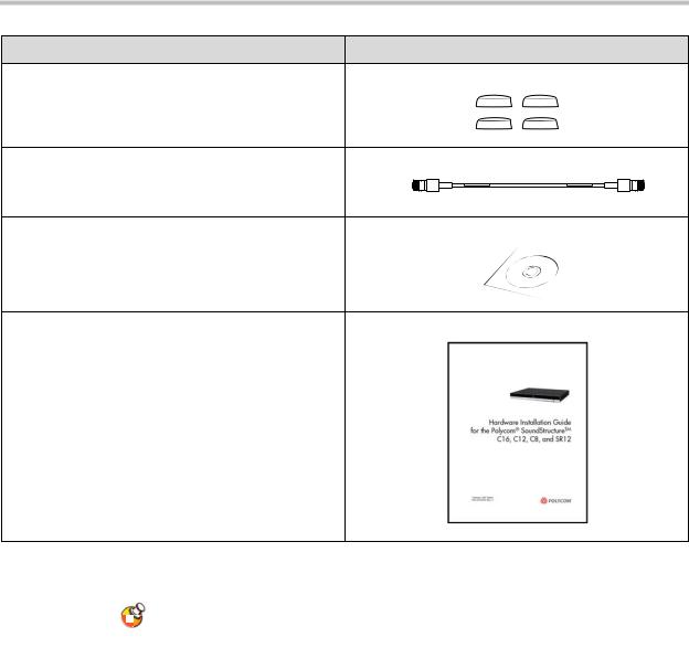
The SoundStructure products include the components shown below.
SoundStructure Device
3.5mm Terminal Blocks
Rack Ears and Rack-Mounting Screws
12” OBAM Cable
Power Cable
Conference Link2 insert plugs
1 - 3
Hardware Installation Guide for the Polycom SoundStructure C16, C12, C8 and SR12
Rubber Feet
18” Conference Link2 Cable
Software CD
Hardware Installation Guide
The SoundStructure C16, C12, SR12, and C8 devices have 33, 25, 25, and 17 terminal block connectors respectively including one for the optional IR receiver accessory.
For a complete list of available SoundStructure Accessories, see Accessories on page 5-1.
1 - 4

Preparing For Installation
Tools Needed For Installation
The following tools will be required to install your Polycom SoundStructure unit:
•A Phillips head screwdriver for installing rack ears and rack-mounting the device.
•A small blade screwdriver for terminating audio cables to the terminal blocks.
Safety Recommendations
Read and understand the following instructions before using the system:
•Always disconnect the system from power before inserting plug-in cards into the SoundStructure device.
•Only connect the system to surge protected power outlets.
•Only use electrical extension cords with a current rating at least equal to that of the system.
•Always disconnect the system from power before cleaning and servicing and when not in use.
•Do not spray liquids directly onto the system when cleaning. Always apply the liquid first to a static free cloth.
•Do not immerse the system in any liquid or place any liquids on it.
•Do not disassemble this system. To reduce the risk of shock and to maintain the warranty on the system, a qualified technician must perform service or repair work.
•Keep ventilation openings free of any obstructions.
•If the system or any accessories are installed in an enclosed space such as a cabinet or equipment rack, ensure that the air temperature in the enclosure does not exceed 40° C (104° F). Forced cooling may be required to keep the equipment within its operating temperature range.
Save these safety instructions.
1 - 5

Hardware Installation Guide for the Polycom SoundStructure C16, C12, C8 and SR12
General Site Requirements
Please ensure the SoundStructure side ventilation holes have at least 1 inch of clearance from the sides of the rack to allow airflow through the device. Failure to maintain clearance for airflow may increase the operating temperature of the unit beyond its maximum operating temperature of 40° C (104° F).
With the proper side clearance, each SoundStructure device requires one rack space and does not require additional empty rack spaces above or below the device. When mounting with other equipment give consideration to having access to the audio connectors on the rear-panel.
When using SoundStructure with Polycom HDX video codecs, it is recommended that the SoundStructure devices be installed above the video codec.
If you are placing the device on a tabletop or other flat surface (rather than rackmounting it), it is recommended to mount the adhesive rubber feet on the bottom of the device as shown in Rack-Mounting The Polycom SoundStructure Device to prevent damaging the finish of the furniture surface.
Power Supply Considerations
The Polycom SoundStructure C16, C12, C8 and SR12 have the following power requirements on the line power supplied to the devices:
•Input voltage of 90-250 VAC; 50-60 Hz
•Line power requirements (including 0.6 PF):
—130 VA (C16),
—115 VA (C12),
—105 VA (SR12),
—95 VA (C8)
1 - 6
2
Installing The SoundStructure C16,
C12, C8, And SR12
This chapter provides information on the Polycom SoundStructure product, rack-mount, and installation procedures.
•Panel Diagrams
•Installing The Hardware
Panel Diagrams
This section describes the front and rear-panels of the Polycom
SoundStructure C16.
Warning
The graphics shown in this guide show the Polycom SoundStructure C16 audio conferencing device. The SoundStructure C12, C8, and SR12 are all very similar in appearance to the C16.
2 - 1

Hardware Installation Guide for the Polycom SoundStructure C16, C12, C8, And SR12
Front-Panel
The front-panel of the Polycom SoundStructure C16 is shown below with the front panel door open, revealing the serial number label and the System Status LED.
SoundStructureTM |
C16 |
Serial number on |
System Status LED |
Front panel door |
|
Front-Panel LED Interpretation
The front-panel LEDs are interpreted as follows:
LED |
Color |
State |
Description |
|
|
|
|
Status |
Green |
Flashing |
The system is |
|
|
|
starting up. |
|
|
|
|
|
|
Solid |
The system is |
|
|
|
operating normally. |
|
|
|
|
|
Yellow |
Solid |
The system has |
|
|
|
logged a warning |
|
|
|
and the system logs |
|
|
|
should be reviewed. |
|
|
|
|
|
Red |
Solid |
A system |
|
|
|
component has |
|
|
|
failed and requires |
|
|
|
immediate |
|
|
|
attention. |
|
|
|
|
2 - 2
Installing The SoundStructure C16, C12, C8, And SR12
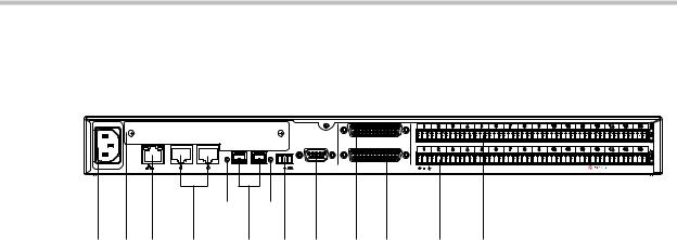
Rear Panel
The rear-panel of the Polycom SoundStructure C16 is shown in the following figure.
|
|
|
PIN 2: TXD |
|
|
|
|
PIN 3: RXD |
|
|
|
|
PIN 5: GROUND |
|
|
|
|
PIN 7: CTS |
|
|
|
|
PIN 8: RTS |
|
|
|
|
RS-232 |
REMOTE CONTROL 1 |
LAN |
C-LINK2 |
IN OBAM OUT |
IR 12V |
REMOTE CONTROL 2 |
57
1 |
2 |
3 |
4 |
6 |
8 |
9 |
10 |
11 |
1 |
2 |
3 |
4 |
5 |
6 |
7 |
8 |
9 |
10 |
11 |
12 |
13 |
14 |
15 |
16 |
OUTPUTS |
1 |
2 |
3 |
4 |
5 |
6 |
7 |
8 |
9 |
10 |
11 |
12 |
13 |
14 |
15 |
16 |
INPUTS |
|
|
|
|
|
|
|
|
|
|
|
|
|
|
|
|
|
|
|
|
|
|
|
|
|
|
|
|
|
|
|
SoundStructureTM C16 |
|
|
12 13
1 |
AC power connection |
8 |
IR receiver interface |
|
|
|
|
2 |
Expansion slot for SoundStructure |
9 |
RS-232 interface |
|
plug-in cards |
|
|
|
|
|
|
3 |
Ethernet interface |
10 |
Logic input and output connector |
|
|
|
|
4 |
Conference Link2 (CLink2) |
11 |
Logic input and output connector 2 |
|
interface |
|
|
|
|
|
|
5 |
OBAM input status LED |
12 |
Balanced audio input connectors |
|
|
|
|
6 |
OBAM input and output ports |
13 |
Balanced audio output connectors |
|
|
|
|
7 |
OBAM output status LED |
|
|
|
|
|
|
Installing The Hardware
To install a SoundStructure device, follow these steps:
•Install optional plug-in card. (See page 2-4.)
•Mount the SoundStructure device onto an equipment rack or other location. (See page 2-6.)
•Connect to LAN for control management. (See page 2-7.)
•Use Conference Link2 to connect to Polycom HDX system. (See page 2-7.)
•Use OBAM to connect multiple SoundStructure devices. (See page 2-9.)
•Connect IR port to optional receiver and/or RS-232 to control system. (See page 2-12.)
•Connect other devices/equipment using analog input/output. (See page 2-14.)
•Connect optional logic devices. (See page 2-15.)
2 - 3

Hardware Installation Guide for the Polycom SoundStructure C16, C12, C8, And SR12
•Connect AC power. (See page 2-19.)
•Configure devices using SoundStructure Studio software. (See page 2-20.)
Plug-in Card Installation
Each SoundStructure device can have a plug-in card installed for a total of eight plug-in cards in a collection of eight SoundStructure devices. When installing more than one plug-in card in an installation, it is recommended to use the plug-in slot from the top device first and continue sequentially down through the collection of devices as additional plug-cards are added.
Warning Do not insert a plug-in card while the SoundStructure is powered on.
Failure to remove power prior to installing the plug-in card may damage the plug-in card and/or the SoundStructure device.
To install a plug-in card, follow these five steps:
1.If plugged in, unplug the AC power cord from the SoundStructure device.
PIN 2: TXD
PIN 3: RXD
PIN 5: GROUND
PIN 7: CTS
PIN 8: RTS
RS-232
LAN |
C-LINK2 |
IN OBAM OUT |
IR 12V |
2. Remove the blank plate and screws from the expansion slot (see below).
PIN 2: TXD
PIN 3: RXD
PIN 5: GROUND
PIN 7: CTS
PIN 8: RTS
RS-232
LAN |
C-LINK2 |
IN |
IR 12V |
2 - 4
Installing The SoundStructure C16, C12, C8, And SR12
3.Insert the plug-in card into the slotted rails and push until it is tight into the slot.
|
|
PHONE LINE |
PIN 2: TXD |
|
|
|
PIN 3: RXD |
|
|
|
PIN 5: GROUND |
|
|
|
PIN 7: CTS |
|
|
|
PIN 8: RTS |
|
|
|
RS-232 |
LAN |
C-LINK2 |
IN |
IR 12V |
4.Tighten the thumbscrews on the rear-panel of the plug-in card.
5.If no further installation steps are required, plug in the AC power cable; otherwise, continue with the remainder of the installation steps prior to applying power.
2 - 5

Hardware Installation Guide for the Polycom SoundStructure C16, C12, C8, And SR12
Rack-Mounting The Polycom SoundStructure Device
The Polycom SoundStructure can be mounted in an equipment rack, or placed on a tabletop or other flat surface, or mounted under the table with the optional undertable mounting kit.
Each SoundStructure device requires one rack space and does not require additional empty rack spaces above or below the device.
When multiple devices are racked together, before final tightening of the rack mount screws on each device after the first one, ensure there is enough clearance so that the front-panel door will open freely.
To rack-mount the SoundStructure unit:
1. |
Remove the four front screws on the enclosure. |
|
|
SoundStructure C16 |
|
2. |
Align the rack ears, and install the rack ears using the screws that were |
|
|
removed from the enclosure. |
|
|
SoundStructure |
C16 |
3. |
Mount the equipment in the rack and secure with the four supplied rack |
|
|
mount screws (screw size is 10-32x1/2"). |
|
SoundStructure |
C16 |
To place on a tabletop or other flat surface:
>>If the equipment will not be mounted in an equipment rack, it is recommended that you install the four adhesive rubber feet on the bottom of the device (as shown below) before placing the equipment on furniture.
2 - 6
Installing The SoundStructure C16, C12, C8, And SR12
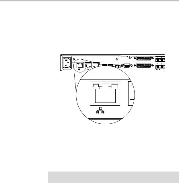
Connecting To The LAN Interface
The SoundStructure device's Ethernet interface (as shown following figure) is a 10/100 Mbps interface that supports Auto-MDIX (medium dependent interface crossover).
Auto-MDIX enables the use of a standard CAT5e cable to connect directly from the SoundStructure device to either an Ethernet network or to a computer. The SoundStructure device will detect the connection and work appropriately.
PIN 2: TXD
PIN 3: RXD PIN 5: GROUND PIN 7: CTS
PIN 8: RTS
RS-232
1 |
2 |
REMOTE CONTROL 1
1 2
REMOTE CONTROL 2
LAN |
By default the SoundStructure device has Dynamic Host Configuration Protocol (DHCP) enabled and will accept an IP address from a DHCP server. The SoundStructure device IP address can also be set to a static IP address using the SoundStructure Studio software.
Do not plug the Ethernet cable in to the Conference Link2 ports. To minimize improper cabling, plastic plugs have been installed by default into the Conference Link2 ports.
Warning Connecting an Ethernet cable into the Conference Link2 interface of a
SoundStructure device could damage the SoundStructure device.
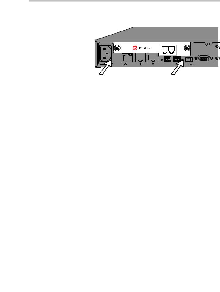
Connecting To Other Polycom Equipment With Conference Link2
The Conference Link2 interface (shown in the following drawing and labeled C-Link2) is used to connect the SoundStructure devices to other Polycom equipment such as a Polycom HDX system. There are two Conference Link2 interfaces on each SoundStructure device to support future connectivity to more than one Polycom device. The Conference Link2 ports on the SoundStructure devices have a plastic plug that must be removed before inserting a cable into the Conference Link2 ports. The Conference Link2 ports
2 - 7
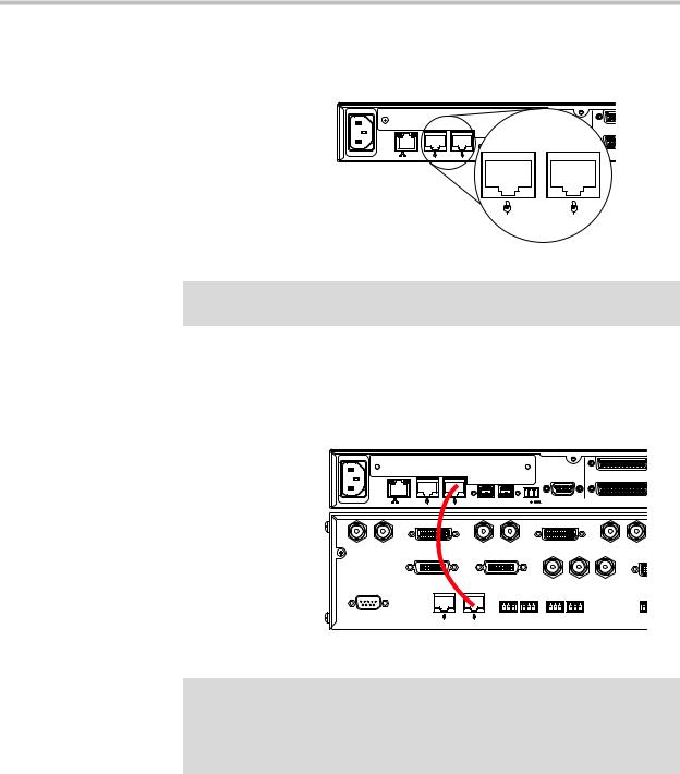
Hardware Installation Guide for the Polycom SoundStructure C16, C12, C8, And SR12
have an RJ45 plug form-factor (with a different pinout from standard Ethernet cables - see Conference Link2 for pinout details) to enable field termination of custom length cables using standard RJ45 plugs and standard crimping tools.
|
|
|
R |
Hz 50/60 |
VAC 250-90 |
|
|
|
LAN |
C-LINK2 |
R |
|
|
|
C-LINK2 |
Warning Connecting a Conference Link2 cable to the Ethernet interface could damage the connecting device and/or the SoundStructure device.
Using the supplied 18” Conference Link2 cable, connect one Conference Link2 port on the SoundStructure device to a Polycom microphone Input port on the Polycom HDX system as shown in the following figure. If there are multiple SoundStructure devices linked together with OBAM Link, only one SoundStructure device should be connected to a Polycom HDX system.
PIN 2: TXD
PIN 3: RXD
PIN 5: GROUND
PIN 7: CTS
PIN 8: RTS
RS-232
VAC 250-90 Hz 50/60
LAN |
C-LINK2 |
IN OBAM OUT |
IR 12V |
REMOTE CONTROL 1
REMOTE CONTROL 2
Warning A CAT5e cable that is terminated with standard T568A or T568B pin/pair assignments will not work with Conference Link2. The Conference Link2 pinout is different from T568A or T568B pin/pair termination.
Do not use a standard Ethernet cable to connect SoundStructure to a Polycom HDX system.
If a longer Conference Link2 cable is required, one may be constructed using the custom pinout (see Conference Link2) and standard 8P8C (eight positions, eight conductors, e.g., RJ45) connectors, shielded Cat5e cable or better, and standard 8P8C crimping tools. Note that the maximum length between the Polycom HDX codec and the SoundStructure device is one hundred feet (30m).
2 - 8
Loading...