


PA
D2000.2
2 - CHANNEL
AM P L I F I E R
HBP2479
TABLE OF CONTENTS
Introduction. . . . . . . . . . . . . . . . . . . . . . . . . . . . . . . . . . . . . . . . . . . . . . . . . . . . . . . . . . . . . . . . . . . . . . . . . . . |
. . |
. . 4 |
WHAT’S IN THE BOX . . . . . . . . . . . . . . . . . . . . . . . . . . . . . . . . . . . . . . . . . . . . . . . . . . . . . . . . . . . . . . . . |
. . |
. . 4. . . . . . |
Listen Carefully . . . . . . . . . . . . . . . . . . . . . . . . . . . . . . . . . . . . . . . . . . . . . . . . . . . . |
. . |
. . 4. . . . . . . . . |
Internal Bridging . . . . . . . . . . . . . . . . . . . . . . . . . . . . . . . . . . . . . . . . . . . . . . . . |
. . |
. 4. . . . . . . . . |
TOOLS OF THE TRADE . . . . . . . . . . . . . . . . . . . . . . . . . . . . . . . . . . . . . . . . . . . . . . . . . . . . . . . . . . . . . . . . . . . . . |
. . |
. . 5 |
End Panel Layouts . . . . . . . . . . . . . . . . . . . . . . . . . . . . . . . . . . . . . . . . . . . . . . . . . . . . . . . . . . . . . . |
. . |
5. -. 6. . . . . |
Line Level Inputs/Outputs/Controls . . . . . . . . . . . . . . . . . . . . . . . . . . . . . . . . . . . . . . . . . . . . . . . . . . . . . . . . |
. . |
. . 5 |
Power Inputs/Speaker Outputs . . . . . . . . . . . . . . . . . . . . . . . . . . . . . . . . . . . . . . . . . . . . . . . . . . . . . . . . . . . |
. . |
. . 6 |
Amplifier Wiring . . . . . . . . . . . . . . . . . . . . . . . . . . . . . . . . . . . . . . . . . . . . . . . . . . . . . . . . . . . . . . . . . . . . . . . |
. . |
6 - 7 |
Power Connections . . . . . . . . . . . . . . . . . . . . . . . . . . . . . . . . . . . . . . . . . . . . . . . . . . . . . . |
. . |
. . 6. . . . . . . . . . |
Speaker Wiring Diagram . . . . . . . . . . . . . . . . . . . . . . . . . . . . . . . . . . . . . . . . . . . . . . . . . . . . . . . . . . . . . . . . |
. . |
. . 7 |
Bridging . . . . . . . . . . . . . . . . . . . . . . . . . . . . . . . . . . . . . . . . . . . . . . . . . . . . . . . . . . . . . . . . . |
. . |
. . 7. . . . . . . . . . . |
Amplifier Installation . . . . . . . . . . . . . . . . . . . . . . . . . . . . . . . . . . . . . . . . . . . . . . . . . . . . . . . . . . . . . . . . . |
. . |
. . 7 |
Mounting Locations . . . . . . . . . . . . . . . . . . . . . . . . . . . . . . . . . . . . . . . . . . . . . . . . . . . . . . . . . . . . . . . . . . . . |
. . |
. . 7 |
Passenger Compartment .. .. .. .. .. .. .. .. .. .. .. .. .. .. .. .. .. .. .. .. .. .. .. .. .. .. .. .. .. .. .. .. .. .. .. .. .. .. .. .. .. .. .. .. .. .. .. .. .. .. .. .. .. .. .. .. .. .. .. .. .. .. .. .. |
.. .. |
.. .. 7 |
Trunk Compartment . . . . . . . . . . . . . . . . . . . . . . . . . . . . . . . . . . . . . . . . . . . . . . . . . . . . . . . . . . . . . . . . . . |
. |
. . . 7. . |
Installation Guidelines . . . . . . . . . . . . . . . . . . . . . . . . . . . . . . . . . . . . . . . . . . . . |
. |
8. -.9. . . . . . . . |
Set Up and Troubleshooting . . . . . . . . . . . . . . . . . . . . . . . . . . . . . . . . . . . . . . . . . . . . |
.9 |
.- .11. . . . . . . . . . |
Testing the System . . . . . . . . . . . . . . . . . . . . . . . . . . . . . . . . . . . . . . . . . . . . . . . . . . |
. |
. . 9. . . . . . . . . |
Adjusting the Sound of the System . . . . . . . . . . . . . . . . . . . . . . . . . . . . . . . . . . . . . . . |
9. |
-. 10. . . . . . . . . . |
Troubleshooting Tips . . . . . . . . . . . . . . . . . . . . . . . . . . . . . . . . . . . . . . . . . . . . . . . . . . . . . . . . . . |
10. . |
-. 11. . . . . . |
Specifications. . . . . . . . . . . . . . . . . . . . . . . . . . . . . . . . . . . . . . . . . . . . . . . . . . . . . . . . . . . . . . . . . . . . . . . . . . . |
. |
. 12 |
Français . . . . . . . . . . . . . . . . . . . . . . . . . . . . . . . . . . . . . . . . . . . . . . . . . . . . . . . . . . |
13. |
.- .22. . . . . . . . . |
Español . . . . . . . . . . . . . . . . . . . . . . . . . . . . . . . . . . . . . . . . . . . . . . . . . . . . . . . . . . . . . . . . . . |
23. |
-. 32. . . . . . . . . . . |
Deutsch . . . . . . . . . . . . . . . . . . . . . . . . . . . . . . . . . . . . . . . . . . . . . . . . . . . . . . . . . . . . . . . . . . . . . . . . . |
33 |
.-. 42. . . . . |
Italiano . . . . . . . . . . . . . . . . . . . . . . . . . . . . . . . . . . . . . . . . . . . . . . . . . . . . . . . . . . . . . . . . . . . . . . . . |
43. |
-. 52. . . . . . |
Português. . . . . . . . . . . . . . . . . . . . . . . . . . . . . . . . . . . . . . . . . . . . . . . . . . . . . . . . . . . . . . . . . . . . . . . . . . . . . . |
53 |
- 62 |
Warranty . . . . . . . . . . . . . . . . . . . . . . . . . . . . . . . . . . . . . . . . . . . . . . . . . . . . . . . . . . . . . . . . . . . . . . . . . . . . . . . |
. |
. 63 |
© 2011 Polk Audio—all rights reserved |
3 |
English Introduction
Thank you for your purchase of a Polk Audio PA D Series amplifier.. Each PA D Series amplifier is designed
to be the leader in its class offering the most power, advanced features, and extreme ease of use.. In high-end sound systems or high SPL systems, PA D Series amplifiers will give you years of trouble-free performance..
• PA D2000.2—250W x 2 RMS @ 2 Ohms; 125W x 2 RMS @ 4 Ohms; 500W x 1 RMS Bridged @ 4 Ohms.. Note: Improper installation will not only limit the performance of your Polk Audio PA D Series amplifier but also potentially compromise the reliability of this amplifier.. To ensure proper sonic results and component reliability, please refer to your authorized dealer for installation assistance or advice.. If you decide to perform the installation yourself, be sure to read the entire manual before beginning the installation (see Installation Guidelines on page 8)..
RECORD THIS INFORMATION FOR YOUR RECORDS
Model:__________________________________________________
Serial Number:____________________________________________
Date of Purchase:__________________________________________
WHAT’S IN THE BOX
• |
Polk Audio Amplifier |
• |
Terminal Block Adaptor |
• |
Phillips Screws (4) |
• |
Owner’s Manual |
• Online Registration Card |
|
|
|
Important Note: If anything is missing or damaged, or if your Polk Audio PA D Series amplifier fails to operate, notify your dealer immediately.. We recommend keeping your original carton and packing materials in case you need to ship the unit in the future..
WARNING: Listen Carefully
Polk Audio amplifiers, loudspeakers and subwoofers are capable of playing at extremely high volume levels, which could cause serious or permanent hearing damage.. Polk Audio accepts no liability for hearing loss, bodily injury or property damage resulting from the misuse of its products.. Keep these guidelines in mind and always use your own good judgment when controlling volume.. For more about safe volume levels,
go to: www..osha..gov/dts/osta/otm/noise/standards_more..html
Internal Bridging
Terminals that can be used in bridging mode are identified by the black boxes above each terminal.. In the PA D2000..2, the two black boxes work together to create an internally bridged hookup..
BRIDGED
|
|
|
|
L |
L |
R |
R |
TOOLS OF THE TRADE
Listed next are the majority of the tools required to perform an installation..
Having the proper tools will make the installation that much easier..
• |
Phillips head screwdriver |
• Solderless, crimp-on connectors and a crimping tool |
• Electric drill and 3/16" and 1/8" drill bits |
• Safety glasses |
|
• |
Permanent ink marker or pencil |
• DMM or VOM |
• |
Safety glasses |
• Nylon tie straps |
• |
Wire strippers and cutters |
• Wire crimper |
• |
Electrical tape |
• Grommets for passing wires through metal car walls |
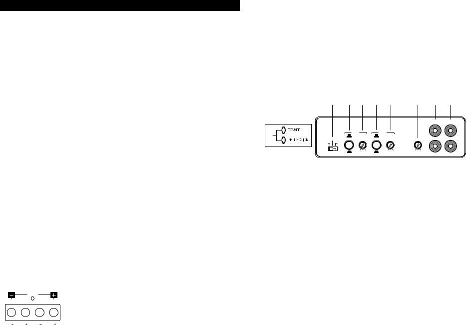
End Panel Layouts
PA D2000.2 Line Level Inputs/Outputs/Controls
2 |
3a |
3b |
4a |
4b |
|
5 |
6 |
7 |
|
|
|
|
|
|
|
INPUT |
OUTPUT |
|
|
LPF |
|
HPF |
|
|
L |
L |
1 |
X-OVER |
X-OVER |
|
|
|
|
||
FREQ x 1 |
|
FREQ x 1 |
|
|
|
|
|
|
HPF |
LPF |
HPF |
LEVEL |
|
|
|||
FULL |
BPF |
|
|
|
|
|
|
|
|
|
|
|
|
|
|
R |
R |
|
FREQ x 10 |
50Hz 500Hz |
FREQ x 10 |
20Hz 400Hz |
6V |
200mV |
|
|
|
|
|
|
|
|
|
||
1.Status LEDs (on top of amplifier): Power and Protection—Power will illuminate to indicate the amplifier is on and operating normally; protection will illuminate if the amplifier shuts down due to short circuit, DC offset, or overheating detected by onboard protection circuitry..
2.HPF, FULL, BPF Switch—Selects full range, high pass filter, or band-pass filter.. The HPF setting attenuates low frequencies and is used with mid-range speakers and tweeters.. The FULL setting does not attenuate any frequencies and is for full range speaker systems.. The BPF setting allows you to use both the high pass filter and low pass filter, and it is for use with mid-range drivers..
3.(a) Low-Pass Frequency Button—Sets the frequency of the crossover at a range of either 50Hz - 500Hz or, when FREQ x 10 is engaged, to 500Hz - 5000Hz.
(b)LPF Variable Control—Adjusts the low pass filter frequency to attenuate frequencies above the setting on the control..
4.(a) High-Pass Frequency Button—Sets the frequency of the crossover at a range
of either 20Hz - 400Hz or, when FREQ x 10 is engaged, to 200Hz - 4000Hz..
(b)HPF Variable Control—Adjusts the high pass filter frequency to attenuate frequencies below the setting on the control..
5.Level Control—Adjusts the gain of the left and right channels to match the output voltage from your head unit..
6.Line Level Inputs—Accepts line level input from a head unit, preamplifier or, equalizer..
7.Line Level Outputs—Provides a full range signal for easy connection to additional amplifiers..
4 |
© 2011 Polk Audio—all rights reserved |
© 2011 Polk Audio—all rights reserved |
5 |
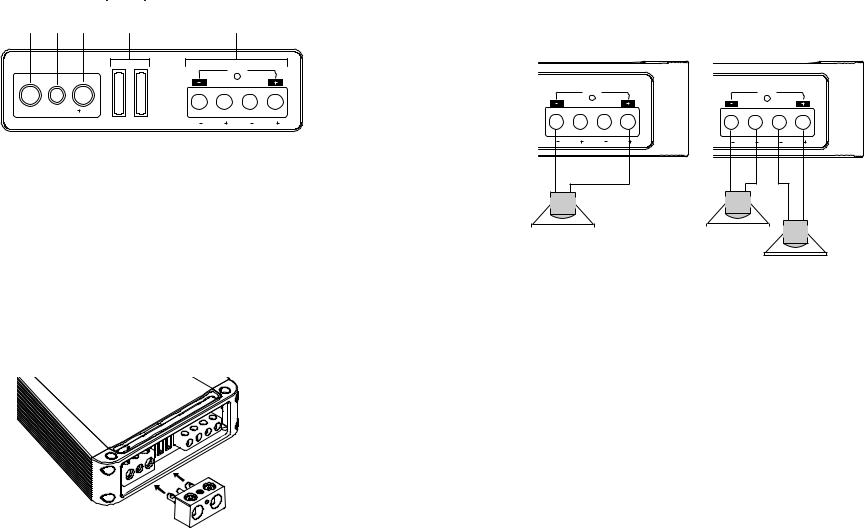
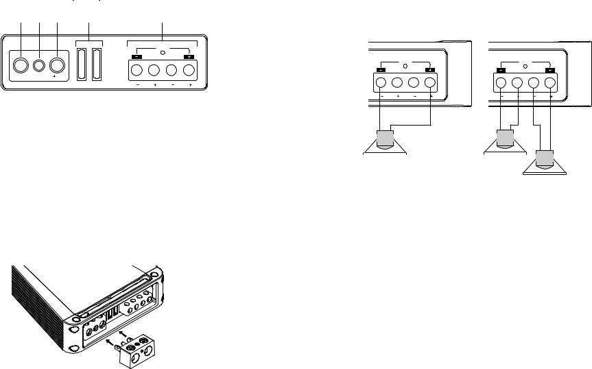
PA D2000.2 Power Inputs/Speaker Outputs
1 |
2 |
3 |
4 |
5 |
BRIDGED
GND |
REM |
12V |
25A |
25A |
L |
L |
R |
R |
1.GND (Ground)—Connect this terminal directly to the metal chassis of the vehicle, using the shortest wire necessary to make this connection. Always use wire of the same gauge or larger than the +12V power
wire.. The chassis connection point should be scraped free of paint and dirt.. Use only quality crimped and/or soldered connectors at both ends of this wire.. DO NOT connect this terminal directly to the vehicle battery ground terminal or any other factory ground points..
2.REM (Remote Turn On)—This terminal turns on the amplifier when +12V is applied to it.
Connect it to the remote turn on lead of the head unit..
3.+12V Power—Connect this terminal through a FUSE or CIRCUIT BREAKER to the positive terminal of the vehicle battery or the positive terminal of an isolated audio system battery..
WARNING: Always protect this power wire by installing a fuse or circuit breaker of the appropriate size within 12" of the battery terminal connection.
4.Fuse—These fuses (25A x 2) protect the amplifier against internal electrical damage and are meant to protect only the amplifier.. All other power connections should be fused at the power source..
5.Speaker Output—Connect the speakers here..
6.Terminal Adaptor—The adaptor enables the use of cable up to 0000AWG for the ground and +12V connections (see illustration below).
6. Terminal Adaptor
Amplifier Wiring
Power Connections
•PA D2000.2 Fuse Size: 2 x 25 AMP ATC.
•Power connections accept up to 4 AWG wire.
•4 AWG power and ground wire recommended for optimal performance.
•Connect +12V to the battery through fuse holder. This connection provides +12V main power to the amplifier.
•Power wire must be fused within 12" of the battery.
•Ground the amplifier using a good chassis ground as close as possible to the amplifier.
•Connect REM terminal to remote turn-on lead from the head unit. This connection provides +12V power to turn-on the amplifier.
•Add extra ground wire between the negative terminal of the battery and the chassis.
Speaker Wiring Diagram PA D2000.2
The Polk Audio PA D2000..2 amplifier offers two positive and two negative output terminals for ease of connecting the speakers to the amplifier.. The amplifier is stable to 2 Ohms per channel or 4 Ohms bridged..
BRIDGED
L |
L |
R |
R |
BRIDGED
L |
L |
R |
R |
|
|
|
|
|
|
|
|
|
|
|
|
|
|
|
|
|
|
|
|
|
|
|
|
|
|
|
|
|
|
|
|
|
|
|
|
|
|
|
|
|
|
|
|
|
|
|
|
|
|
|
|
|
|
|
|
|
|
|
|
|
|
|
|
|
|
|
|
|
|
|
|
|
|
|
|
|
|
|
|
|
|
|
|
|
|
|
|
|
|
|
|
|
|
|
|
|
|
|
|
|
|
|
|
|
|
4Ω min |
|
|
|
|
|
2Ω min |
|
|
|
|
|
|
|
|
|
|
|
|
|||||||||||||||
|
|
|
|
|
|
|
|
|
|
|
|
|
|
|
|
|
|
|||||||||||||||||
2Ω min
Bridging
The amplifier is capable of bridging a left and right terminal into a single full range channel with higher output power.. For instance, the L-/R+ channels when wired as shown will increase the output power from 125W per channel to a 500W channel (for a 4 Ohm load).. The most common are shown in the figure above: two full range channels or a bridged subwoofer channel..
Internal Bridging
Terminals that can be used in bridging mode are identified by the black boxes next to each terminal.. In the PA D2000..2, the two black boxes work together to create an internally bridged hookup..
Amplifier Installation
Mounting Locations
The location of your amplifier will depend on several important issues.. Due to the low profile and compact
size of the Polk Audio PA D Series amplifier, there are many possible installation locations that will yield satisfactory amplifier performance.. Always mount the amplifier in a place that protects the amplifier from the elements..
In addition, mount the amplifier on a stable, flat surface..
NOTE: Mounting amplifiers upside down is not recommended and may cause premature thermal shutdown..
WARNING! Do not mount any amplifier in the engine compartment.. Amplifiers are not designed to endure the harsh environment of an engine compartment..
Passenger Compartment
If you are going to mount the amplifier in the passenger compartment, make sure you have adequate room for ventilation. When mounting your amplifier under a seat or similar area, keep a minimum of 1" of clearance around the amplifier for adequate cooling..
Trunk Compartment
Mounting your amplifier in the trunk provides excellent performance as long as you do not restrict the airflow around the heatsink of the amplifier.. For optimal results, mount the amplifier with as much clearance as possible.. This type of mounting will yield the best cooling due to the convection effect of the amplifier chassis..
6 |
© 2011 Polk Audio—all rights reserved |
© 2011 Polk Audio—all rights reserved |
7 |
INSTALLATION GUIDELINES
Power for systems with a single amplifier can be supplied by most automotive electrical systems.. Systems with multiple amplifiers may require a higher capacity battery, alternator or the use of a storage capacitor.. Polk Audio PA D Series amplifiers do generate a certain amount of heat as part of normal operation.. Be sure the area around the amplifier
is unobstructed to allow adequate air circulation.. Remember, beach blankets, last week’s laundry, school books and homework papers placed on top of the amplifier impede air flow and may cause damage..
1.Please read this owner’s manual carefully before installing your amplifier..
2.Disconnect the battery ground terminal prior to making any electrical connections..
3.Check for any hazards or obstructions such as gas tanks, fuel or brake lines, and wiring harnesses before mounting the amplifier..
4.Pick a mounting location that will provide adequate access and ventilation and protect the amplifier from heat, moisture, and dirt..
5.Avoid sharp metal areas when routing cables to the amplifier, and run RCA cables away from the power cables and other potentially noisy car harnesses..
6.The amplifier should be grounded with a short, heavy gauge wire connected directly to the car at a bare metal surface, preferably scraped body metal.. Do not use factory ground locations, seat bolts, or brackets that are spot welded..
7.Always fuse your power connection within 12 inches of the battery terminal.. Use a fuse or circuit breaker rated slightly more than the on-board fuse(s) of the amplifier(s).. The gauge of power wire used should take into account the total current draw of the system, and the length of wire used.. IASCA and other auto sound competition organizations have charts available for this; you can also find a chart in the MECP study guide.. Minimum wire gauge recommendations for the individual amplifiers are listed on the specification page.. Always use the same gauge wire for the amplifier ground that you use for the power wire.. Be sure
to examine the battery ground cable of the vehicle, and if necessary, upgrade it by adding an additional ground wire that is the same gauge as the amplifier’s power wire.. Remember, the amplifier can only deliver its rated output when it is not current limited by the power and ground supply wires..
8.This amplifier is designed to drive a speaker load that measures from 2 to 8 Ohms (4 Ohms minimum bridged).. Keep in mind that heat is the long-term enemy of automotive electronics and the lower your speaker load, the more heat is generated.. For low-impedance speaker applications or restricted ventilation installations,
an external cooling fan may be advisable..
9.Battery and ground connections to the vehicle should be made with crimped ring terminals of the appropriate size (surface area is what counts;) soldering the terminals after crimping is also recommended..
10.Due to the high-frequency MOSFET switching power supply, filtering the power cable is not generally required (remember that the amp can’t deliver full output if the power supply is restricted..) Proper grounding of the signal source is mandatory for the amplifier to reach its performance peak.. If the RCA inputs are not grounded adequately via the signal source, electrical noise from the vehicle may be picked up in the system..
Step By Step Installation
1.Determine the location for the amplifier.. Refer to the Mounting Locations section of this guide for detailed information..
2.Decide on the system configuration for your amplifier.. For system suggestions, refer to the Speaker Wiring Diagrams section of this guide..
3.Run all the wires from the amplifier location to the speakers, source unit, and battery.. Do not connect the battery at this time.. Be sure to run Line levels and power and speaker wires away from factory electrical wires and system as they pose a great potential for induced system noise..
4.Pre-drill amplifier mounting holes.. Be sure to “think before you drill..“ Gas tanks, fuel lines, and other obstructions have a nasty way of hiding themselves.. For best results use a marking pen to mark the mounting holes and pre-drill these holes with a standard 1/8" drill bit.
5.Mount the amplifier.. Make sure the amplifier is mounted on a flat surface.. If this is not possible, do not over tighten the screws so that the chassis of the amplifier is twisted or bent..
6.Turn the vehicle’s key switch to the off position..
7.Disconnect the vehicle’s battery ground terminal..
8.Connect power wires to the amplifier (ground first, then +12V and REM).
9.Connect the line level and speaker wires to the amplifier.. Check the quality of your speakers and signal connections.. This will determine the ultimate performance of your Polk Audio PA D Series amplifier.. Refer to the Line Level Inputs/Outputs/Controls and Speaker Wiring Diagrams sections of this guide for correct wiring instructions..
10.Reconnect the ground terminal to the battery after power, speaker, and line level connections are completed..
11.Set crossovers.. Refer to the Line Level Inputs/Outputs/Controls section of this manual for detailed instructions..
12.Once satisfied that all connections and settings are correct, install the fuse located near the vehicle’s battery and proceed to the Testing the System section of this manual..
WARNING! Never exceed the recommended fuse size of this amplifier.. Failure to do so will result in the voiding of your warranty and possible damage to the amplifier..
SET UP AND TROUBLESHOOTING
Testing the System
After you have completed the installation, you need to test the system.. This will help ensure years of trouble-free operation.. Please refer to the listed steps below when testing the sound of your Polk Audio PA D Series amplifier..
1.Check all the wiring connections to be sure they are correct and secure..
2.Turn the signal source volume control all the way down.. Set any tone controls to their flat or defeated positions.. This includes the loudness control..
3.Turn the level controls of the amplifier to their minimum positions..
4.Turn the head unit on.. Check to see if the power LED located on the connection side of the amplifier is on.. If not, please refer to the Power Inputs/Speaker Outputs and the Troubleshooting Tips sections of this manual for instructions..
5.If using an aftermarket head unit, turn the level controls of the amplifier about one quarter of a turn counterclockwise.. Slowly increase the volume level of the head unit so that you can hear the output of the system.. If no sound is heard or if the output is distorted, turn the system off immediately.. Refer to the Power Inputs/Speaker Outputs and the Troubleshooting Tips sections of this manual to solve your installation problems..
6.Check to make sure the output for each channel is correct.. If the active crossovers are used, check to make sure that each output is correct from the amplifier.. When using active crossovers on midrange and tweeters, do not use crossover frequencies lower than recommended.. If the system is not configured properly,
refer to the Line Level Inputs/Outputs/Controls section of this manual and take corrective action..
7.If the output is clear and undistorted, continue to the Adjusting the Sound of the System section of this manual..
Adjusting the Sound of the System
Once you have checked the system’s operation, adjust the sound of the system.. Adjusting the sound of the system is accomplished by setting the level controls and adjusting the internal crossovers (see Line Level Inputs/Outputs/Controls on page 5)..
1.Turn the signal source volume control all the way down.. Set any tone controls to their flat or defeated positions.. This includes the loudness control..
2.Turn the level controls of the amplifier to their minimum positions..
3.Choose music with high dynamic content that you like, with which you are familiar, and will be used most often in the system..
4.Turn the head unit’s volume control up to its highest undistorted output level.. If you lack
test equipment, this point occurs between 3/4 to full volume depending on the quality of your source unit.. Listen for any audible distortion.. If any distortion is audible, reduce the volume of the source unit until you have an undistorted output.. Leave the volume control at this position during your system tuning..
5.While listening to your chosen dynamic music, turn up the level control corresponding
to the midrange output until you hear slight distortion and turn the level control back slightly for an undistorted output.. Depending on your system, the midrange and tweeter output may be on the same output channels..
8 |
© 2011 Polk Audio—all rights reserved |
© 2011 Polk Audio—all rights reserved |
9 |

6.Turn up the level control corresponding to the tweeter output until you hear slight distortion and turn back the level control slightly for an undistorted output.. Depending on your system the midrange and tweeter output may be on the same output channels..
7.Fine-tune the output level between midrange and tweeters.. Refer to the Line Level Inputs/Outputs/Controls section of this manual for detailed instructions..
8.Repeat Steps 5-7 for the rear speakers.. If you do not have rear speakers continue to Step 10..
9.Set levels between the front and rear midrange and tweeters for optimum front/rear balance..
10.Turn up the level control corresponding to the woofer output until you hear slight distortion and turn back the level control slightly for an undistorted output..
11.Fine-tune the output level between satellite speakers and the woofers.. Refer to the Line Level Inputs/Outputs/Controls section of this manual for controls.. Adjust the level to the bass output of the woofer to match the sonic requirements of the system..
12.Enjoy your awesome Polk Audio PA D Series amplifier..
Troubleshooting Tips
Symptom |
Probable Cause |
Action To Take |
|
|
|
No output |
|
|
|
|
|
|
Low or no remote turn-on.. |
Check remote turn-on at amplifier and repair as needed.. |
|
|
|
|
Fuse blown.. |
Check power wire’s integrity and check for |
|
|
speaker shorts.. Fix as needed and replace fuse.. |
|
|
|
|
Power wires not connected.. |
Check power wire and ground connections |
|
|
and repair or replace as needed.. |
|
|
|
|
Audio input not connected.. |
Check line level connections and repair |
|
|
or replace as needed.. |
|
|
|
|
Speaker wires not connected.. |
Check speaker wires and repair or replace as needed.. |
|
|
|
|
Speakers are blown.. |
Check system with known working speaker |
|
|
and repair or replace speakers as needed.. |
|
|
|
Audio cycles on and off |
|
|
|
|
|
|
Thermal protection engages when |
Make sure there is proper ventilation for |
|
amplifier heat sink temperature |
amplifier and improve ventilation as needed.. |
|
exceeds 85° C (185° F).. |
|
|
|
|
|
Loose or poor audio input.. |
Check line level connections and repair |
|
|
or replace as needed.. |
|
|
|
|
Loose power connections.. |
Check power wires and ground connections |
|
|
and repair or replace as needed.. |
|
|
|
Distorted output |
|
|
|
|
|
|
Amplifier level sensitivity set |
Readjust gain.. Refer to the Adjusting the Sound |
|
too high exceeding maximum |
of the System section of this manual.. |
|
capability of amplifier.. |
|
|
|
|
|
Impedance load to amplifier too low.. |
Check speaker impedance load if below |
|
|
(2 Ohms, 4 Ohms min bridged); rewire |
|
|
speakers to achieve higher impedance.. |
|
|
|
|
Shorted speaker wires.. |
Check speaker wires and repair or replace as needed.. |
|
|
|
|
Speaker not connected |
Check speaker wires and repair or replace as needed.. |
|
to amplifier properly.. |
|
|
|
|
Troubleshooting Tips
Symptom |
Probable Cause |
Action To Take |
|
|
|
Distorted output |
|
|
|
|
|
|
Internal crossover not |
Readjust crossovers.. Refer to the Amplifier Settings |
|
set properly for speakers |
section of this manual for detailed instructions.. |
|
|
|
|
Speakers are blown |
Check system with known working speakers |
|
|
and fix or replace as needed.. |
|
|
|
Poor bass response |
|
|
|
|
|
|
Speakers wired with wrong polarity |
Check speaker polarity and fix as needed.. |
|
causing cancellation at low frequencies.. |
|
|
|
|
|
Crossover set incorrectly.. |
Reset crossovers.. Refer to the Line Level |
|
|
Input/Output/Control section of this manual.. |
|
|
|
|
Impedance load at amplifier is too low.. |
Check speaker impedance load if below |
|
|
(2 Ohms, 4 Ohms min bridged); rewire |
|
|
speakers to achieve higher impedance.. |
|
|
|
Battery fuse blowing |
|
|
|
|
|
|
Short in power wire or incorrect wiring.. |
Check power wires and ground connections |
|
|
and repair or replace as needed.. |
|
|
|
|
Fuse used is smaller than recommended.. |
Replace with proper fuse size.. |
|
|
|
|
Actual current exceeds fuse rating.. |
Check speaker impedance load if below |
|
|
(2 Ohms, 4 Ohms min bridged); rewire |
|
|
speakers to achieve higher impedance.. |
|
|
|
Amplifier fuse blowing |
|
|
|
|
|
|
Fuse used is smaller than recommended.. |
Replace with proper fuse size.. |
|
|
|
|
Impedance load at amplifier is too low.. |
Check speaker impedance load if below |
|
|
(2 Ohms, 4 Ohms min bridged); rewire |
|
|
speakers to achieve higher impedance.. |
|
|
|
|
Speaker is blown with shorted outputs.. |
Check system with known working speakers |
|
|
and fix or replace as needed.. |
|
|
|
|
Actual current exceeds fuse rating.. |
Check speaker impedance load if below |
|
|
(2 Ohms, 4 Ohms min bridged); rewire |
|
|
speakers to achieve higher impedance.. |
|
|
|
10 |
© 2011 Polk Audio—all rights reserved |
© 2011 Polk Audio—all rights reserved |
11 |

Specifications
Amplifier |
PA D2000.2 |
|
|
Type |
Bridgeable |
|
Class D MOSFET |
|
|
Channels |
2 channel |
|
|
RMS Continuous Power |
125 W x 2 |
@ 4 Ohms |
|
|
|
RMS Continuous |
250 W x 2 |
Power @ 2 Ohms |
|
|
|
RMS Continuous Power |
500 W x 1 |
Bridged @ 4 Ohms |
|
|
|
Distortion at Rated Power |
< 0..1% |
|
|
Minimum Impedance Bridged |
4 Ohms |
|
|
Minimum Impedance |
2 Ohms |
Not Bridged |
|
|
|
Signal-to-noise Ratio |
105 dB |
|
|
Frequency Response |
20Hz - 20kHz |
|
|
Damping Factor |
>100 |
|
|
Crossover Filter Slope |
12 dB/octave |
(dB/octave) |
|
|
|
Filter Switch |
3-position |
|
(HPF, Full & BPF) |
|
|
High Pass Filter |
20Hz - 4kHz |
Frequency Range |
|
|
|
Amplifier |
PA D2000.2 |
|
|
|
|
Low Pass Filter |
50Hz - 5kHz |
|
Frequency Range |
|
|
|
|
|
High Level Inputs (y/n/) |
No |
|
|
|
|
Line Level Inputs (y/n) |
Yes |
|
|
|
|
Line Level Outputs (y/n) |
Yes |
|
|
|
|
LED Power Indicator |
Yes |
|
|
|
|
LED Protection Indicator |
Yes |
|
|
|
|
Input Sensitivity |
200mV - 6V |
|
|
|
|
Supply Voltage |
10V - 16V |
|
|
|
|
Fusing & Power/Type |
(2) 25 Amp ATC |
|
|
|
|
Power Connections |
4 |
AWG |
|
|
|
Ground Connections |
4 |
AWG |
|
|
|
Speaker Connections |
12 AWG |
|
|
|
|
Height |
1 |
13/16" (46 mm) |
|
|
|
Depth |
6 |
3/4" (171.5 mm) |
|
|
|
Width |
8 |
1/4" (209.6 mm) |
|
|
|
Width w/ Terminal Adaptor |
9" (228.6 mm) |
|
|
|
|
Weight |
3..75 lbs (1..7 kg) |
|
|
|
|
TABLE DES MATIÈRES
Introduction. . . . . . . . . . . . . . . . . . . . . . . . . . . . . . . . . . . . . . . . . . . . . . . . . . . . . . . . . . . . . . . . . . . . . . . . . . . |
. . . |
14 |
CONTENU DE LA BOÎTE . . . . . . . . . . . . . . . . . . . . . . . . . . . . . . . . . . . . . . . . . . . . . . . . . . . . . . . . . . . . . . . . . . . . |
. . . |
14 |
ÉCOUTEZ BIEN . . . . . . . . . . . . . . . . . . . . . . . . . . . . . . . . . . . . . . . . . . . . . . . . . . . . . . . . . |
. . . |
14. . . . . . . . . . |
PONTAGE INTERNE . . . . . . . . . . . . . . . . . . . . . . . . . . . . . . . . . . . . . . . . . . . . . . . . . . . . . . . . . . . . |
. . . |
14. . . . . . . . . . . |
OUTILS REQUIS . . . . . . . . . . . . . . . . . . . . . . . . . . . . . . . . . . . . . . . . . . . . . . . . . . . . . . . . . . . . . . . . . . . . . . . . . . . |
. . . |
15 |
CONFIGURATION DES PANNEAUX . . . . . . . . . . . . . . . . . . . . . . . . . . . . . . . . . . . . . . . . . . . . . . . . . . . . . . . . . . |
15 - 16 |
|
Entrées niveau de ligne/sorties/contrôles . . . . . . . . . . . . . . . . . . . . . . . . . . . . . . . . . . . . . . . |
. . . |
15. . . . . . . . . . . |
Entrées de puissance/sorties haut-parleur . . . . . . . . . . . . . . . . . . . . . . . . . . . . . . . . . . . . . . . . . . . . . . . . . . |
. . . |
16 |
CÂBLAGE DE L’AMPLIFICATEUR . . . . . . . . . . . . . . . . . . . . . . . . . . . . . . . . . . . . . . . . . . . . . . . . . . . . . . |
16. . -. 17. . . |
|
Connexion de l’alimentation . . . . . . . . . . . . . . . . . . . . . . . . . . . . . . . . . . . . . . . . . . . . . . . . . . . . . . . . . |
. . . |
16. . . . |
Diagramme du câblage des haut-parleurs . . . . . . . . . . . . . . . . . . . . . . . . . . . . . . . . . . . . . . . . . |
. . . |
17. . . . . . . . . |
Pontage . . . . . . . . . . . . . . . . . . . . . . . . . . . . . . . . . . . . . . . . . . . . . . . . . . . . . . . . . . . |
. . . |
17. . . . . . . . . . |
INSTALLATION DE L’AMPLIFICATEUR . . . . . . . . . . . . . . . . . . . . . . . . . . . . . . . . . . . . . . . . |
. . . |
17. . . . . . . . . |
Emplacement . . . . . . . . . . . . . . . . . . . . . . . . . . . . . . . . . . . . . . . . . . . . . . . . . . . . |
. . . |
17. . . . . . . . . . |
Habitacle . . . . . . . . . . . . . . . . . . . . . . . . . . . . . . . . . . . . . . . . . . . . . . . . . . . . . . . . . . . . . . . . |
. . . . |
17. . . . . . . . . . . |
Coffre . . . . . . . . . . . . . . . . . . . . . . . . . . . . . . . . . . . . . . . . . . . . . . . . . . . . . . . . . . . . . . . . . . . . . . . . . . . . . . . |
. . . |
17 |
CONSEILS POUR L’INSTALLATION . . . . . . . . . . . . . . . . . . . . . . . . . . . . . . . . . . . . . . . . . . . |
18. -. |
19. . . . . . . . . . |
RÉGLAGE ET GUIDE DE DÉPANNAGE . . . . . . . . . . . . . . . . . . . . . . . . . . . . . . . . . . . . . . . . . . . . . . . . . . . . . . . . |
19 - 21 |
|
Vérification du système . . . . . . . . . . . . . . . . . . . . . . . . . . . . . . . . . . . . . . . . . . . . . . . . . . . . . . . . . . . . . . . . . |
. . . |
19 |
Réglage du son du système. . . . . . . . . . . . . . . . . . . . . . . . . . . . . . . . . . . . . . . . . . . . . . . . . . . . . . . . . . . . . . |
19 - 20 |
|
Conseils de dépannage . . . . . . . . . . . . . . . . . . . . . . . . . . . . . . . . . . . . . . . . . . . . . . . . . . . . . . . . . . . . . . . . . |
20 - 21 |
|
SPÉCIFICATIONS. . . . . . . . . . . . . . . . . . . . . . . . . . . . . . . . . . . . . . . . . . . . . . . . . . . . . . . . . . . . . . . . . . . . . . . . . . |
. . . |
22 |
GARANTIE . . . . . . . . . . . . . . . . . . . . . . . . . . . . . . . . . . . . . . . . . . . . . . . . . . . . . . . . . . . . . . . . |
. . . |
63. . . . . . . . . . |
12 |
© 2011 Polk Audio—all rights reserved |
© 2011 Polk Audio—all rights reserved |
13 |

FrançaisIntroduction
Merci d’avoir acheté un amplificateur Polk Audio PA D Series.. Chaque amplificateur PA D Series a été conçu pour dominer sa catégorie.. Il vous offre une puissance maximale, des caractéristiques de pointe et une utilisation des plus faciles. Au coeur d’une chaîne audio haut de gamme ou à niveaux sonores élevés, un amplificateur PA D
Series vous assurera des années de haute performance ultra fiable..
• PA D2000.2—250W x 2 RMS @ 2 Ohms; 125W x 2 RMS @ 4 Ohms; 500W x 1 RMS Ponté @ 4 Ohms.. Note: Une installation fautive limitera non seulement la performance de votre amplificateur Polk Audio PA D Series mais pourrait également compromettre sa fiabilité.. Pour assurer une performance sonore optimale
et la fiabilité des composants, consultez votre revendeur Polk Audio agréé pour de l’assistance ou des conseils.. Si vous décidez de faire l’installation vous-même, assurez-vous de bien lire ce manuel en entier avant de procéder à l’installation. (Voir le «Guide d’installation» à la page 18.)
CONSERVEZ CETTE INFORMATION DANS VOS DOSSIERS
Modèle:__________________________________________________
No de série:_______________________________________________
Date de l’achat:____________________________________________
CONTENU DE LA BOÎTE
• |
Amplificateur Polk Audio |
• |
Manuel d’utilisation |
• |
Adaptateur de bornier |
• |
Vis Phillips (4) |
• |
Carte d’enregistrement en ligne |
|
|
Note Importante: S’il manque des pièces, si vous découvrez des avaries ou si votre amplificateur Polk Audio
PA D Series ne fonctionne pas, contactez immédiatement votre revendeur.. Conservez la boîte et l'emballage— ils assureront la protection du produit en cas de transit éventuel..
AVERTISSEMENT: ÉCOUTEZ BIEN!
Les amplificateurs, haut-parleurs et subwoofers Polk Audio sont capables de générer des niveaux de pression sonore extrêmement élevés pouvant causer des dommages auditifs graves ou permanents.. Polk Audio Inc.. ne peut être tenue responsable de perte d’ouïe, de blessure corporelle ou de dommages matériaux résultant de l’usage abusif de ses produits.. Tenez compte de cet avertissement et faites preuve de discernement lorsque vous contrôlez le volume..
Pour plus d’information sur les niveaux sécuritaires de pression sonore visitez: www..osha..gov/dts/osta/otm/noise/standards_more..html
PONTAGE INTERNE
Les bornes qui peuvent être utilisées en mode pontage sont identifiées par des cases noires situées au dessus des bornes appropriées.. Les deux cases noires du PA D2000..2 travaillent ensemble pour créer un pontage interne..
BRIDGED
|
|
|
|
L |
L |
R |
R |
OUTILS REQUIS
Voici une liste de la plupart des outils requis pour faire l’installation.
L’utilisation d’outils appropriés rendra l’installation beaucoup plus facile..
• |
Tournevis Phillips |
• |
Câble d’alimentation pour l’amplificateur |
• |
Fiches à sertir sans soudure et outil sertisseur |
• |
Coupe-fil / dénude-fil |
• |
Perceuse électrique et forets 3/16" et 1/8" |
• |
Outil sertisseur |
• |
Lunettes de sécurité |
• |
Ruban isolant |
• |
Crayon feutre ou crayon à mine |
• Passe-fils pour traverser les cloisons |
|
• |
Multimètre DVOM ou VOM |
|
métalliques du véhicule |
• |
Attaches en nylon |
|
|
CONFIGURATION DES PANNEAUX
PA D2000.2 Entrées/sorties niveau de ligne/Contrôles
2 |
3a |
3b |
4a |
4b |
|
5 |
6 |
7 |
|
|
|
|
|
|
|
INPUT |
OUTPUT |
|
|
LPF |
|
HPF |
|
|
L |
L |
1 |
X-OVER |
X-OVER |
|
|
|
|
||
FREQ x 1 |
|
FREQ x 1 |
|
|
|
|
|
|
HPF |
LPF |
HPF |
LEVEL |
|
|
|||
FULL |
BPF |
|
|
|
|
|
|
|
|
|
|
|
|
|
|
R |
R |
|
FREQ x 10 |
50Hz 500Hz |
FREQ x 10 |
20Hz 400Hz |
6V |
200mV |
|
|
|
|
|
|
|
|
|
||
1.DEL POWER et PROTECTION (sur le dessus de l’ampli)—La DEL POWER luit lorsque l’amplificateur est sous tension et fonctionne normalement. La DEL PROTECTION luit lorsque l’ampli s’éteint suite à la détection d’un court circuit, d’un décalage de courant continu ou de surchauffe par le circuit de protection interne..
2.HPF, FULL, BPF—Ce contrôle sélectionne le mode: pleine gamme, filtre passe-haut ou filtre passe-bande.. Le mode HPF (passe-haut) atténue les basses fréquences et est indiqué pour les haut-parleurs de médiums et les tweeters. Le mode FULL ne filtre aucune fréquence et est indiqué pour les systèmes de haut-parleurs pleine gamme.. Le mode BPF (passe-bande) permet l’utilisation simultanée des filtres passe-haut et passebas et est indiqué pour les haut-parleurs de médiums.
3.(a) Bouton LPF—X-OVER—La gamme de fréquences du séparateur à la position FREQ X 1
est 50 Hz - 500 Hz; à la position FREQ X 10 elle est 500 Hz - 5000 Hz.
(b)Contrôle LPF—Règle la fréquence du filtre passe-bas pour atténuer les fréquences supérieures au réglage du contrôle..
4.(a) Bouton HPF—X-OVER— La gamme de fréquences du séparateur à la position FREQ X 1 est 20 Hz - 400 Hz; à la position FREQ X 10 elle passe à 200 Hz - 4000 Hz.
(b)Contrôle HPF—Règle la fréquence du filtre passe-haut pour atténuer les fréquences inférieures au réglage du contrôle..
5.LEVEL—Règle le gain du canal pour l’apparier au voltage de sortie du composant de source.
6.INPUTS—Entrées niveau de ligne d’un composant de source, préamplificateur ou correcteur..
7.OUTPUTS—Sorties de ligne du signal pleine gamme pour connexion à des amplificateurs additionnels.
14 |
© 2011 Polk Audio—all rights reserved |
© 2011 Polk Audio—all rights reserved |
15 |
PA D2000.2 Alimentation/Sorties Haut-Parleurs
1 |
2 |
3 |
4 |
5 |
BRIDGED
GND |
REM |
12V |
25A |
25A |
L |
L |
R |
R |
1.GND (Masse)—Connectez cette borne au châssis métallique du véhicule en utilisant un câble le plus court possible et de même calibre (ou plus gros) que le câble d’alimentation +12V. La zone de contact avec le châssis
du véhicule doit être poncée et nettoyée pour retirer toute peinture ou saleté. N’utilisez que des connecteurs à sertir ou à souder de première qualité aux deux extrémités du câble. NE RACCORDEZ PAS cette borne directement à la borne de masse de la batterie ou à tout autre point de masse original du véhicule.
2.REM—Cette prise permet d’allumer l’amplificateur à distance lorsqu’elle capte du courant +12 V. Branchez-y le câble de mise sous tension à distance +12V du composant de source.
3.+12V—Raccordez cette prise via un FUSIBLE ou un DISJONCTEUR à la borne positive de la batterie du véhicule ou à la borne positive d’une batterie dédiée à la chaîne audio du véhicule.
AVERTISSEMENT: Protégez toujours ce câble d’alimentation en installant un fusible ou un disjoncteur de valeur appropriée à moins de 30 cm de la connexion à la borne de la batterie.
4.Fuse—Ces fusibles (25A x 2) protègent l’amplificateur—et uniquement l’amplificateur— contre les dommages électriques internes.. Tout autre composant électrique doit avoir son propre fusible de protection à la source d’alimentation.
5.Sorties haut-parleur — Connectez les haut-parleurs ici..
6.Adaptateur de bornier — Cet adaptateur permet d’utiliser des câble de calibre jusqu’à 0000AWG pour les connexions +12V et la masse. (Voir l’illustration ci-dessous.)
6. Adaptateur de bornier
CÂBLAGE DE L’AMPLIFICATEUR
Alimentation
•PA D2000.2 type de fusibles: 2 x 25 AMP ATC.
•Connexion de l’alimentation—câble de calibre jusqu’à 4 AWG.
•Pour une performance maximale, utilisez du câble de calibre 4 AWG pour l’alimentation et la masse.
•Connectez le câble d’alimentation +12 V à la batterie via un fusible.
•Le fusible du câble d’alimentation doit être à moins de 30 cm de la batterie .
•Faites une mise à la masse de l’amplificateur au châssis le plus près possible de l’amplificateur.
•Branchez le câble de mise sous tension à distance du composant de source (+12 V) dans la prise REM. Cette fonction permet d’allumer l’amplificateur à distance.
•Ajoutez un câble de masse additionnel entre la borne négative de la batterie et le châssis.
Diagramme du câblage des haut-parleurs—PA D2000.2
L’amplificateur Polk Audio PA D2000..2 offre deux jeux de bornes de sorties (positives et négatives) pour faciliter la connexion des haut-parleurs. L’amplificateur est stable à 2 Ohms par canal et à 4 Ohms en mode ponté.
BRIDGED
L |
L |
R |
R |
BRIDGED
L |
L |
R |
R |
|
|
|
|
|
|
|
|
|
|
|
|
|
|
|
|
|
|
|
|
|
|
|
|
|
|
|
|
|
|
|
|
|
|
|
|
|
|
|
|
|
|
|
|
|
|
|
|
|
|
|
|
|
|
|
|
|
|
|
|
|
|
|
|
|
|
|
|
|
|
|
|
|
|
|
|
|
|
|
|
|
|
|
|
|
|
|
|
|
|
|
|
|
|
|
|
|
|
|
|
|
|
|
|
|
|
4Ω min |
|
|
|
|
|
2Ω min |
|
|
|
|
|
|
|
|
|
|
|
|
|||||||||||||||
|
|
|
|
|
|
|
|
|
|
|
|
|
|
|
|
|
|
|||||||||||||||||
2Ω min
Pontage
L’amplificateur peut ponter les canaux pleine gamme gauche et droit pour créer un seul canal pleine gamme plus puissant..
Par exemple, le pontage des sorties L-/R+ (câblés tel qu’illustré) augmente la puissance de 125 W par canal à 500 W pour un seul canal (en 4 Ohms).. Les configurations les plus courantes sont illustrées ici: deux canaux pleine gamme ou un canal de subwoofer ponté..
Ponotage Interne
Les bornes qui peuvent être utilisées en mode pontage sont identifiées par des cases noires situées au dessus des bornes appropriées.. Les deux cases noires du PA D2000..2 travaillent ensemble pour créer un pontage interne..
INSTALLATION DE L’AMPLIFICATEUR
Emplacement
L’emplacement de votre amplificateur dépend de plusieurs facteurs importants.. L’amplificateur Polk Audio
PA D Series est mince et compact et peut donc être installé convenablement à plusieurs endroits. N’installez l’amplificateur que dans un lieu protégé des éléments et sur une surface plate et stable..
NOTE: Il est déconseillé d’installer l’amplificateur à l’envers. Ceci pourrait causer un arrêt thermique prématuré.
AVERTISSEMENT! N’INSTALLEZ JAMAIS un amplificateur dans le compartiment-moteur. Les amplificateurs ne sont pas conçus pour supporter l’environnement périlleux d’un compartiment-moteur..
Habitacle
Si vous comptez installer l’amplificateur dans l’habitacle, allouez un espace de dégagement suffisant pour assurer une ventilation adéquate. Si vous installez l’amplificateur sous un siège ou un autre endroit restreint, allouez au moins 2,5 cm de dégagement autour de l’amplificateur..
Coffre
Le coffre est un endroit idéal pour installer l’amplificateur à condition d’allouer un espace de dégagement suffisant pour assurer la ventilation de son dissipateur thermique.. Pour une performance optimale, allouez
un dégagement maximal car l’effet de convection du châssis de l’amplificateur favorisera son refroidissement..
16 |
© 2011 Polk Audio—all rights reserved |
© 2011 Polk Audio—all rights reserved |
17 |
CONSEILS POUR L’INSTALLATION
Le système électrique de la plupart des véhicules peut fournir l’électricité requise par les chaînes audio utilisant un seul amplificateur.. Les chaînes utilisant plusieurs amplificateurs pourraient nécessiter une batterie de plus haute capacité, un alternateur ou un condensateur. Les amplificateurs Polk Audio PA D Series génèrent de la chaleur. Allouez un dégagement suffisant autour de l’amplificateur pour assurer une ventilation adéquate.. Soyez conscient qu’une couverture, un sac de linge, des vêtements, etc.., peuvent entraver la circulation d’air et occasionner la surchauffe de l’amplificateur..
1.Lisez ce manuel attentivement avant de procéder à l’installation de l’amplificateur.
2.Déconnectez la borne de mise à la masse de la batterie avant de faire toute connexion électrique.
3.Identifiez les obstacles et dangers potentiels—comme le réservoir à essence, les conduits d’essence et de liquide de freins et les faisceaux électriques—avant d’installer l’amplificateur..
4.Choisissez un lieu d’installation accessible qui assurera la protection de l’amplificateur contre les éléments, la chaleur, l’humidité et la poussière tout en lui assurant une ventilation adéquate.
5.Ne passez pas de câbles à proximité de rebords métalliques tranchants. Passez les câbles RCA loin des câbles d’alimentation et des faisceaux de fils qui pourraient causer de l’interférence électromagnétique..
6.L’amplificateur doit être mis à la masse à l’aide d’un câble de gros calibre le plus court possible connecté directement au métal dénudé de la voiture, préférablement au métal poncé du châssis. N’utilisez pas les points de masse d’origine, les boulons des sièges ou les supports soudés par points.
7. Installez toujours le fusible du câble d’alimentation à moins de 30 cm des bornes de la batterie. Utilisez un fusible ou un disjoncteur de valeur nominale légèrement plus élevée que celle du (des) fusible(s) de bord de (des) l’amplificateur(s). Le calibre du câble d’alimentation doit être proportionnel à l’appel de courant total du système et à la longueur du câble. Vous pouvez vous procurer des tableaux de référence à ce sujet à la IASCA, la MECP et autres associations de compétition.. La fiche technique de ce manuel offre des recommandations pour le calibre minimum de câble à utiliser avec les amplificateurs spécifiques. Utilisez toujours le même calibre de câble pour la masse et l’alimentation de l’amplificateur. Examinez bien le câble de mise à la masse de la batterie du véhicule; si son cali bre n’est pas assez gros, ajoutez un câble de mise à la masse de même calibre que celui du câble d’alimentation de l’amplificateur. N’oubliez pas qu’un amplificateur ne peut pas livrer sa pleine puissance nominale si le courant est restreint par des câbles de mise à la masse et d’alimentation de calibre insuffisant.
8.Cet amplificateur est conçu pour alimenter des haut-parleurs avec une charge d’impédance de 2 à 8 Ohms (minimum 4 Ohms en mode ponté). N’oubliez pas que la chaleur est l’ennemi à long terme de l’électronique automobile et que plus la charge d’impédance est basse, plus de chaleur est générée.. Pour des applications
à très basse impédance ou des installations où la ventilation est restreinte, un ventilateur externe est recommandé.
9.Les connexions aux bornes de la batterie et à la masse doivent être faites à l’aide de cosses à sertir circulaires de format approprié (la surface de contact est primordiale).. Il est également recommandé de souder les câbles après les avoir sertis.
10.Grâce au bloc d’alimentation à commutation hautes fréquences MOSFET, le câble d’alimentation ne requiert général ment pas de filtre (n’oubliez pas que l’amplificateur ne peut pas fournir sa pleine puissance si son alimentation est restreinte). Cependant une mise à la masse adéquate du composant de source est indispensable à la performance optimale de l’amplificateur. Si les entrées RCA ne sont pas adéquatement mises à la masse par le câble du com posant de source, de l’interférence électromagnétique pourrait dégrader la performance de la chaîne..
Installation Etape Par Etape
1.Déterminez l’emplacement de l’ampli. Référez-vous à la section «Emplacement» de ce manuel.
2.Déterminez la configuration du système pour votre ampli. Pour des suggestions, référez-vous à la section «Diagramme du câblage des haut-parleurs» de ce manuel.
3.Tirez tous les câbles partant de l’amplificateur jusqu’aux haut-parleurs, au composant de source et à la batterie. Ne connectez pas la batterie à ce moment-ci. Assurez-vous de tirer tous les câbles de niveau
de ligne, d’alimentation et des haut-parleurs loin des fils électriques originaux du véhicule car ces derniers pourraient causer de l’interférence électromagnétique..
4.Pré-percez les trous pour l’installation de l’ampli mais «pensez avant de percer.» Notez bien la position du réservoir et des conduits d’essence. Pour de meilleurs résultats, marquez les endroits à percer avec un crayon-feutre et pré-percez les trous avec un foret de 1/8".
5. Installez l’amplificateur.. Assurez-vous de l’installer sur une surface plate.. Si ce n’est pas possible, ne serrez pas trop les vis pour éviter de plier ou de tordre le châssis de l’amplificateur..
6.Mettez la clé du véhicule à la position «off».
7.Déconnectez la borne de masse de la batterie du véhicule..
8.Connectez les câbles d’alimentation à l’amplificateur (masse d’abord, puis +12V et REM).
9. Connectez les câbles de niveau de ligne et des haut-parleurs à l’amplificateur. Vérifiez l’intégrité de toutes les connexions car la performance ultime de votre amplificateur Polk Audio PA D Series en dépend.. Référezvous aux sections «Entrées niveau de ligne/sorties/contrôles» et «Diagramme du câblage des haut-parleurs» de ce manuel pour des instructions détaillées..
10. Reconnectez la borne de masse de la batterie après avoir vérifié toutes les connexions d’alimentation, de niveau de ligne et de haut-parleurs..
11.Réglez les séparateurs. Référez-vous à la section «Entrées niveau de ligne/sorties/contrôles» de ce manuel pour des instructions détaillées..
12. Après avoir vérifié toutes les connexions et tous les réglages, installez le fusible situé près de la batterie du véhicule et passez à la section «Vérification du système» de ce manuel.
AVERTISSEMENT! N’utilisez JAMAIS de fusible excédant la valeur recommandée pour cet amplificateur. Vous pourriez endommager l’amplificateur et la garantie serait automatiquement annulée.
RÉGLAGE ET DÉPANNAGE
Vérification Du Système
Après avoir terminé l’installation, vous devrez vérifier le système. Ceci vous assurera des années d’opération fiable.
Référez-vous aux étapes énumérées ci-dessous pour vérifier le son de votre amplificateur Polk Audio PA D Series..
1. Vérifiez l’intégrité de toutes les connexions.
2. Baissez le volume du composant de source au minimum.. Réglez les contrôles de tonalité
(incluant «loudness») à la position “O,” «Off» ou «defeat.»
3.Baissez les contrôles de volume de l’amplificateur au minimum..
4.Allumez le composant de source.. Assurez-vous que la DEL POWER située sur le dessus de l’amplificateur est allumée. Si elle ne l’est pas, consultez les sections «Alimentation/Sorties haut-parleur» et «Conseils de dépannage» de ce manuel.
5.Si vous utilisez un composant de source de marque indépendante, réduisez les contrôles de gain de l’amplificateur d’environ un quart de tour.. Montez lentement le volume du composant de source
pour entendre le signal de ce composant.. S’il n’y a pas de son ou si le son est distortionné, éteignez le système immédiatement. Consultez les sections «Alimentation/Sorties haut-parleur» et «Conseils de dépannage.»
6. Assurez-vous que la sortie de chaque canal est correcte.. Si vous utilisez des séparateurs actifs, assurez-vous que chaque sortie de l’amplificateur est correcte.. Lorsque vous utilisez des séparateurs actifs pour les haut-parleurs de médiums et les tweeters, n’utilisez pas de fréquences plus basses que celles qui sont recommandées. Si le système n’est pas configuré correctement, consultez
la section «Entrées niveau de ligne/sorties/contrôles.»
7. Si la sortie est claire et sans distorsion, procédez à la section «Réglage du son du système» de ce manuel.
Réglage Du Son Du Système
Après avoir vérifié l’opération électronique du système, réglez le son en réglant les contrôles de niveau et les contrôles des séparateurs internes (voir «Entrées niveau de ligne/sorties/contrôles» à la page 15).
1.Baissez le volume du composant de source au minimum.. Réglez les contrôles de tonalité
(incluant «loudness») à la position “O,” «Off» ou «defeat.»
2.Baissez les contrôles de volume de l’amplificateur au minimum..
3.Faites jouer un style de musique dynamique que vous ferez souvent jouer sur cette chaîne..
4.Montez le volume du composant de source jusqu’à ce que vous entendiez de la distorsion.
Si vous n’utilisez pas d’appareil de contrôle, ce niveau devrait se situer entre 75% et 100% du volume (selon la qualité de votre composant de source).. Écoutez bien.. Si vous entendez
de la distorsion, réduisez le volume de votre composant de source jusqu’à ce qu’elle disparaisse. Laissez le contrôle de volume à cette position durant le réglage du système.
18 |
© 2011 Polk Audio—all rights reserved |
© 2011 Polk Audio—all rights reserved |
19 |
 Loading...