


 Loading...
DI900/DI950 FastPac™
Document Inserting System
Operator Guide
US/Canada English Version

Statement of FCC Compliance
This equipment has been tested and found to comply with the limits for a Class A digital device, pursuant to part 15 of the FCC rules. These limits are designed to provide reasonable protection against interference when the equipment is operated in a commercial environment. This equipment generates, uses, and can radiate radio frequency energy and, if not installed and used in accordance with the instruction manual, may cause interference to radio communications. Operation of this equipment in a residential area is likely to cause interference, in which case the user will be required to correct the interference at his own expense.
CAUTION: Changes or modifications to this equipment not expressly approved by the party responsible for compliance (Pitney Bowes) could void the user’s authority to operate the equipment.
Canada
This class A digital apparatus complies with Canadian ICES-003.
Cet appareil numérique de la classe A est conforme á la norme NMB-003 du Canada.
SV61311 Rev. E ©2006 Pitney Bowes Inc.
All rights reserved. This book may not be reproduced in whole or in part in any fashion or stored in a retrieval system of any type or transmitted by any means, electronically or mechanically, without the express, written permission of Pitney Bowes. We have made every reasonable effort to ensure the accuracy and usefulness of this manual; however, we cannot assume responsibility for errors or omissions or liability for the misuse or misapplication of our products.
Due to our continuing program of product improvement, equipment and material specifications as well as performance features are subject to change without notice. DM Series, DM800i, DM1000, SwiftStart, SureTrac, Optiflow, IntelliLink and E-Z Seal are trademarks or registered trademarks of Pitney Bowes. Tyvek is a registered trademark of Dupont.

Table of Contents
Contact Information List
USA Contacts.................................................................................. |
v |
Canada Contacts............................................................................. |
v |
1 • Introduction
A Note to the Operator................................................................ |
1-2 |
Viewing this Guide as a PDF File................................................ |
1-2 |
About Your System...................................................................... |
1-3 |
Standard Systems................................................................. |
1-4 |
System Options*.................................................................... |
1-5 |
Safety Information....................................................................... |
1-6 |
Warning Labels............................................................................ |
1-7 |
Book Contents............................................................................. |
1-8 |
2 • Meet the Inserting System
System Components................................................................... |
2-2 |
Feeder Tower.............................................................................. |
2-4 |
Feeder Trays............................................................................... |
2-5 |
Sheet Trays........................................................................... |
2-5 |
Insert Trays............................................................................ |
2-6 |
Manual Feeder............................................................................ |
2-7 |
Transport Deck............................................................................ |
2-8 |
Mail Piece Path..................................................................... |
2-8 |
Pre-fold Accumulator............................................................. |
2-8 |
Folder.................................................................................... |
2-9 |
Post-fold Accumulator .......................................................... |
2-9 |
Insertion Area........................................................................ |
2-9 |
Folder Bypass Path............................................................... |
2-9 |
Moistener, Closer, Sealer...................................................... |
2-9 |
About the Control Panel............................................................ |
2-10 |
Screen Option Keys............................................................ |
2-10 |
Fixed Function Keys............................................................ |
2-11 |
Machine Action Keys........................................................... |
2-13 |
Screen Navigation Keys...................................................... |
2-13 |
Display Screen.......................................................................... |
2-14 |
Header Area........................................................................ |
2-14 |
Status Area.......................................................................... |
2-15 |
Access Rights............................................................................ |
2-20 |
Logging In............................................................................ |
2-21 |
Logging Out......................................................................... |
2-21 |
SV61311 Rev. E |
|

Table of Contents
About System Covers................................................................ |
2-22 |
Opening the Covers............................................................ |
2-23 |
Closing the Covers.............................................................. |
2-23 |
About the Paper Release Knobs/Levers................................... |
2-24 |
About Add-On Modules............................................................. |
2-24 |
3 • Basic Operation
Connecting to Power................................................................... |
3-2 |
Powering Up................................................................................ |
3-2 |
Home Screen.............................................................................. |
3-3 |
Job Overview............................................................................... |
3-4 |
Selecting the Job......................................................................... |
3-5 |
Setting Up Feeders and Loading Materials................................. |
3-6 |
Attaching Trays to the Feeder Tower..................................... |
3-6 |
Removing Trays from the Feeder Tower............................... |
3-7 |
Loading Material into the Trays............................................. |
3-8 |
Loading the DI950 High Capacity Envelope Feeder |
|
(HCEF)................................................................................ |
3-13 |
Making Pre-Run Adjustments ................................................... |
3-18 |
Adjusting the Envelope Openers......................................... |
3-18 |
Running a Trial Piece................................................................ |
3-22 |
Reviewing the Job Settings................................................. |
3-24 |
Starting the Job......................................................................... |
3-25 |
SwiftStart™ Jobs......................................................................... |
3-25 |
Using SwiftStart™ ................................................................ |
3-26 |
Creating a Job........................................................................... |
3-26 |
Job Options............................................................................... |
3-30 |
Envelope Options................................................................ |
3-30 |
Fold Options........................................................................ |
3-32 |
Sheet Options...................................................................... |
3-33 |
Insert Options...................................................................... |
3-36 |
Editing a Job.............................................................................. |
3-39 |
Modifying Job Settings........................................................ |
3-40 |
Editing an Item.................................................................... |
3-40 |
Adding an Item.................................................................... |
3-41 |
Moving an Item.................................................................... |
3-43 |
Deleting an Item.................................................................. |
3-44 |
4 • Advanced Operation
Overview..................................................................................... |
4-2 |
Using the Alphanumeric Matrix.................................................... |
4-2 |
ii |
SV61311 Rev. E |

Table of Contents |
|
|
|
Saving a Job ............................................................................... |
4-3 |
Deleting a Job............................................................................. |
4-4 |
Assigning User IDs and Passwords............................................ |
4-5 |
Enabling and Disabling the High Capacity Sheet Feeder |
|
(HCSF)........................................................................................ |
4-5 |
5 • Troubleshooting and Maintenance |
|
Adjusting Screen Brightness and Contrast.................................. |
5-2 |
Setting the Time and/or Date....................................................... |
5-3 |
Changing the Language.............................................................. |
5-4 |
Refilling the Sealing Solution....................................................... |
5-5 |
Handling Material Stoppages...................................................... |
5-5 |
Clearing a Stoppage.............................................................. |
5-5 |
Resuming the Job................................................................. |
5-6 |
Handling Outsorted Material.................................................. |
5-6 |
Troubleshooting Tables............................................................... |
5-7 |
Routine Maintenance................................................................ |
5-16 |
Daily Tasks.......................................................................... |
5-16 |
Replacing the Moistener Wick............................................. |
5-16 |
Replacing the Moistener Brushes....................................... |
5-18 |
6• Reference |
|
Overview..................................................................................... |
6-2 |
System Specifications................................................................. |
6-2 |
Component Specifications........................................................... |
6-4 |
Feeder Tower and Base Material Specifications......................... |
6-7 |
General Information............................................................... |
6-7 |
Outer Envelopes.................................................................... |
6-7 |
Inserts.................................................................................. |
6-10 |
Sheets................................................................................. |
6-11 |
High Capacity Sheet Feeder (HCSF) Material Specifications... |
6-12 |
General Information............................................................. |
6-12 |
Sheets................................................................................. |
6-12 |
Materials Not Certified for Use............................................ |
6-13 |
7 • Add-On Modules |
|
About the Add-On Modules......................................................... |
7-2 |
High Capacity Sheet Feeder (HCSF).......................................... |
7-2 |
Loading the HCSF................................................................. |
7-3 |
Adjusting the HCSF Guides.................................................. |
7-5 |
Flats Sealer................................................................................. |
7-7 |
Replacing the Envelope Edge Marker Roller........................ |
7-8 |
SV61311 Rev. E |
iii |

Table of Contents
Attached Printer........................................................................... |
7-9 |
Loading the Attached Printer............................................... |
7-10 |
Adjusting the Printer Interface Guides................................. |
7-11 |
Printing a Cover Sheet to the Top of the Attached Printer... |
7-13 |
SureTrac™ Process Verification System.................................... |
7-13 |
Exit Options............................................................................... |
7-15 |
DM Series™ Mailing System Interface |
|
(DM800i™ or DM1000™ only)............................................... |
7-15 |
OptiFlow™ Vertical Power Stacker ...................................... |
7-18 |
OptiFlow™ Belt Stacker........................................................ |
7-18 |
Exit Transport...................................................................... |
7-18 |
8 • Scanning
Scanning Overview..................................................................... |
8-2 |
OMR...................................................................................... |
8-2 |
BCR....................................................................................... |
8-2 |
Scanning Features................................................................ |
8-4 |
Setting Up a New Scan Configuration......................................... |
8-6 |
Setting Up an OMR Scan Configuration................................ |
8-6 |
Setting Up a BCR Scan Configuration.................................. |
8-9 |
Editing a Scan Configuration..................................................... |
8-13 |
Editing an OMR Scan Configuration................................... |
8-13 |
Editing a BCR Scan Configuration...................................... |
8-14 |
Copying a Scan Configuration................................................... |
8-15 |
Deleting a Scan Configuration................................................... |
8-15 |
Reviewing a Scan Configuration............................................... |
8-16 |
Viewing the Job List.................................................................. |
8-16 |
Assigning a Scan Configuration to an Existing Job .................. |
8-17 |
Adjusting the Scan Heads......................................................... |
8-19 |
Adjusting the Scan Heads for Ladder Orientation Marks.... |
8-19 |
OMR Specifications................................................................... |
8-24 |
Barcode Specifications ............................................................. |
8-26 |
Setting the OMR Scanning Area............................................... |
8-29 |
Defining the First Mark Position and Code Length.................... |
8-29 |
Defining the Clear Zone............................................................ |
8-30 |
Additional Information................................................................ |
8-31 |
BCR and OMR Mark Levels...................................................... |
8-31 |
Basic Level.......................................................................... |
8-32 |
Enhanced Integrity Level..................................................... |
8-34 |
Selective Operations Level.................................................. |
8-35 |
iv |
SV61311 Rev. E |

|
Table of Contents |
|
|
Appendix A • Glossary |
|
Basic Terms ................................................................................ |
A-2 |
Material References.............................................................. |
A-2 |
Machine Functions................................................................ |
A-3 |
Icon Glossary.............................................................................. |
A-4 |
Envelope Icons...................................................................... |
A-4 |
Fold Icons.............................................................................. |
A-5 |
Sheet Icons........................................................................... |
A-5 |
Insert Icons............................................................................ |
A-6 |
Feeder Assignment Icons...................................................... |
A-7 |
Other Icons............................................................................ |
A-7 |
Index |
|
Index....................................................................................... |
I-1 |
SV61311 Rev. E

Table of Contents
This page is intentionally blank.
vi |
SV61311 Rev. E |

Contact Information List
USA Contacts
Product Name - DI900 or DI950
▪For frequently asked questions, go to: www.pb.com and click on Customer Support.
▪To place requests for service or training, go to: www.pb.com and click on My Account.
▪To order supplies and accessories, call the Supply Line™ at: 1.800.243.7824 or go to: www.pb.com and click on Online Store.
▪To view and pay invoices online, go to: www.pb.com and click on My Account.
▪To view inventory, go to: www.pb.com and click on My Account.
▪For direct questions, call: 1.800.522.0020. Customer Service Representatives are available Monday through Friday, 8:00 AM - 8:00 PM ET.
•To obtain Material Safety Data Sheets, call the Supply Line™ or go to: www.pb.com and click on Customer Support.
Canada Contacts
Product Name - DI900 or DI950
▪For frequently asked questions or to order supplies, go to: www.pitneybowes.ca
▪For direct questions, call: 1.800.672.6937. Customer Service Representatives are available Monday through Friday, 8:30 AM - 4:00 PM ET.
SV61311 Rev. E

Contact Information List
This page is intentionally blank.
vi |
SV61311 Rev. E |
1 • Introduction
A Note to the Operator................................................................. |
1-2 |
Viewing this Guide as a PDF File................................................. |
1-2 |
About Your System....................................................................... |
1-3 |
Standard Systems.................................................................. |
1-4 |
System Options...................................................................... |
1-5 |
Safety Information........................................................................ |
1-6 |
Warning Labels............................................................................ |
1-7 |
Book Contents.............................................................................. |
1-8 |
SV61311 Rev. E |
1-1 |
1 • Introduction
A Note to the Operator
Viewing this Guide as a PDF File
It is important to be familiar with this guide as it will enable you to utilize the system to its full potential, while keeping problems to a minimum.
There are several built-in features you can use to navigate through this guide when viewing it as a pdf file:
•Topics highlighted by a blue rectangle are hyperlinks.
Using the Hand tool ( ), you can click anywhere within a hyperlink to jump to the topic's location in the Help guide.
Highlighted Hyperlink
•Entries in the main Table of Contents and the table of contents at the beginning of every chapter are hyperlinks, although they are not highlighted.
Move the Hand tool over a table of contents entry until it points, then click to jump to the location of the entry in the Help guide.
Table of Contents Hyperlink
•Page numbers in the Index are hyperlinks, although they are not highlighted.
Move the Hand tool over the page number until it points, then click on the page number to jump to that page of the Help guide.
Index Hyperlink
1-2 |
SV61311 Rev. E |
Introduction • 1
About Your
System
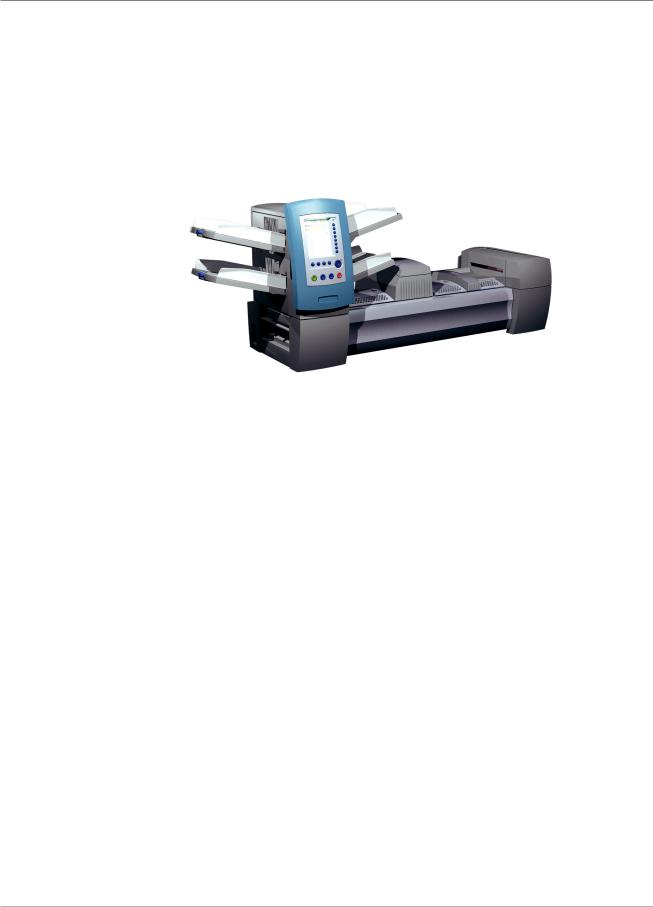
DI900/DI950 are high throughput, mail creation systems designed to handle a broad range of applications with minimum operator setup adjustments. These systems have the ability to feed, fold, and insert mail piece components into an outer envelope. The systems generate Letters or Flats as the final mail piece. The systems also accept a variety of options that provide a wide range of capacities and operating speeds.
Figure 1.1: The DI900 System
The systems can be configured with four flexible Feeder Trays. There are two types of Feeder Trays:
•Sheet Trays, which are capable of feeding sheets; and
•Insert Trays, which are capable of feeding slip/insert materials, pre-fold- ed inserts, thin booklets, and envelopes.
In addition, the DI950 system is equipped with a dedicated High Capacity Envelope Feeder (HCEF) that allows for greater speed and throughput. The systems also accept material from optional upstream input devices, such as High Capacity Sheet Feeders, Attached Printer, and other devices.
Basic system features are summarized in this chapter. Refer to Chapter 6 for detailed equipment and material specifications.
The systems are configured with two major components:
•Feeder Tower, and
•Transport Deck.
The Feeder Tower sends material from the Feeder Trays to the Transport Deck. Depending on the job parameters, the material may or may not need to pass through the Folder in the Transport Deck. If it does, the system offers numerous types of folds and the ability to insert the folded material into the appropriate position in the mail piece collation. The system can also seal the envelope (Letter only) before sending the final mail piece to a stacking unit.
SV61311 Rev. E |
1-3 |
1 • Introduction
Standard
Systems
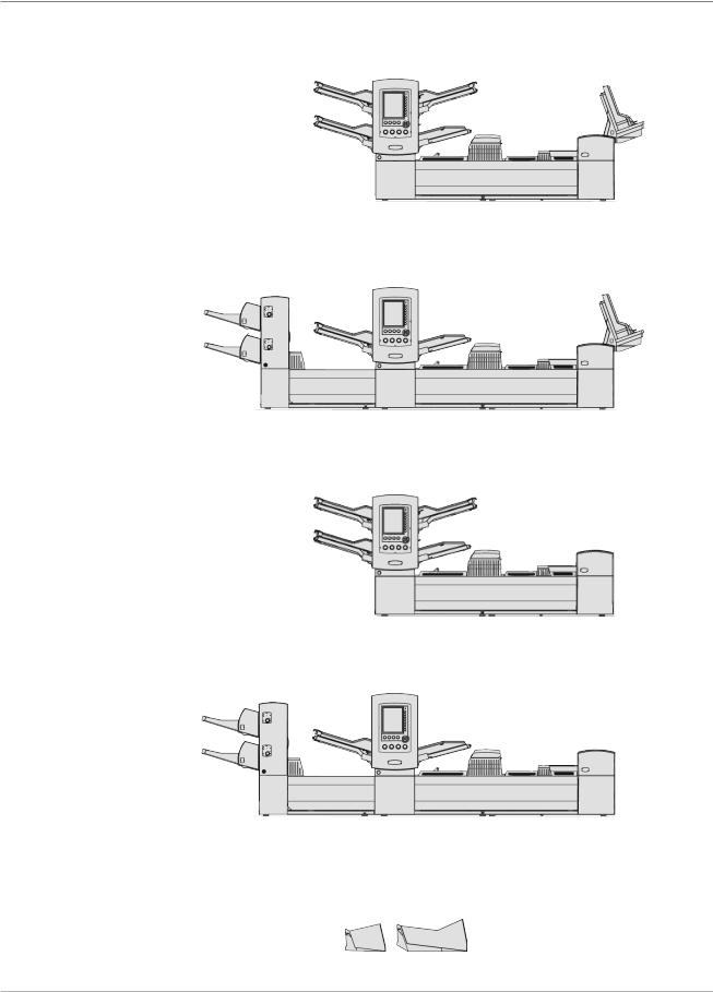
DI950C
DI950H
DI900C
DI900H
Letter and Flats Drop Stacker (standard on all systems)
1-4 |
SV61311 Rev. E |
Introduction • 1
System Options*
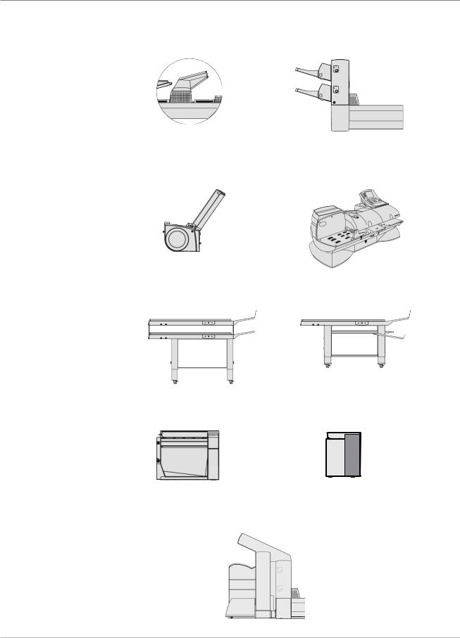
*Furniture, designed specifically for the system, is also available.
Fold Expansion Kit |
High Capacity Sheet |
(Document Inverter) |
Feeder (HCSF) |
OptiFlow™ Vertical |
DM Series™ Mailing System |
Power Stacker |
DM800i™, DM1000™ |
Tandem Belt Stacker |
Belt Stacker |
Exit Transport |
Flats Sealer |
||
|
|
|
|
|
|
|
|
Attached Printer
SV61311 Rev. E |
1-5 |

1 • Introduction
Safety
Information
Follow these precautions whenever you use your inserting system:
•Read all instructions before you attempt to operate the system. Keep the Operator Guide accessible for quick reference.
•Use this equipment only for its intended purpose.
•Place the system close to an easily accessible wall outlet.
•Place the system in an accessible location to allow for proper venting of the equipment and to facilitate servicing.
•Use the power cord supplied with the machine and plug it into a properly grounded wall outlet that is located near the machine and easily accessible. Failure to properly ground the machine can result in severe personal injury and/or fire.
•The power cord wall plug is the primary means of disconnecting the machine from the AC supply.
•DO NOT use a wall outlet controlled by a wall switch or one that is shared with other equipment.
•DO NOT use an adapter plug on the line cord or wall outlet.
•DO NOT remove the ground pin from the line cord.
•Make sure the area in front of the wall outlet into which the machine is plugged is free from obstruction.
•DO NOT route the power cord over sharp edges or trap it between pieces of furniture. Make sure there is no strain on the power cord.
•To reduce the risk of fire or electrical shock, DO NOT attempt to remove covers or disassemble the control panel or its base. The cabinet encloses hazardous parts. If you should damage the unit, contact Your system supplier. Refer to the Contact Information List at the front of this guide for more information.
•If the unit becomes damaged, unplug it from the wall, then contact Your system supplier. Refer to the Contact Information List at the front of this guide for more information.
•Keep fingers, long hair, jewelry and loose clothing away from moving parts at all times.
•Avoid touching moving parts or materials while the machine is in use. Before clearing a jam, be sure machine mechanisms come to a complete stop.
•Remove jammed material gently and carefully.
•Do not place lighted candles, cigarettes, cigars, etc., on the system.
•To prevent overheating, do not cover vent openings.
•Use only approved supplies, in particular aerosol duster. Improper storage and use of aerosol dusters or flammable aerosol dusters, can cause an explosive-like condition that could result in a personal injury and/or property damage. Never use aerosol dusters labeled flammable and always read instructions and safety precautions on the duster container label.
1-6 |
SV61311 Rev. E |
Introduction • 1
Safety Information (continued)
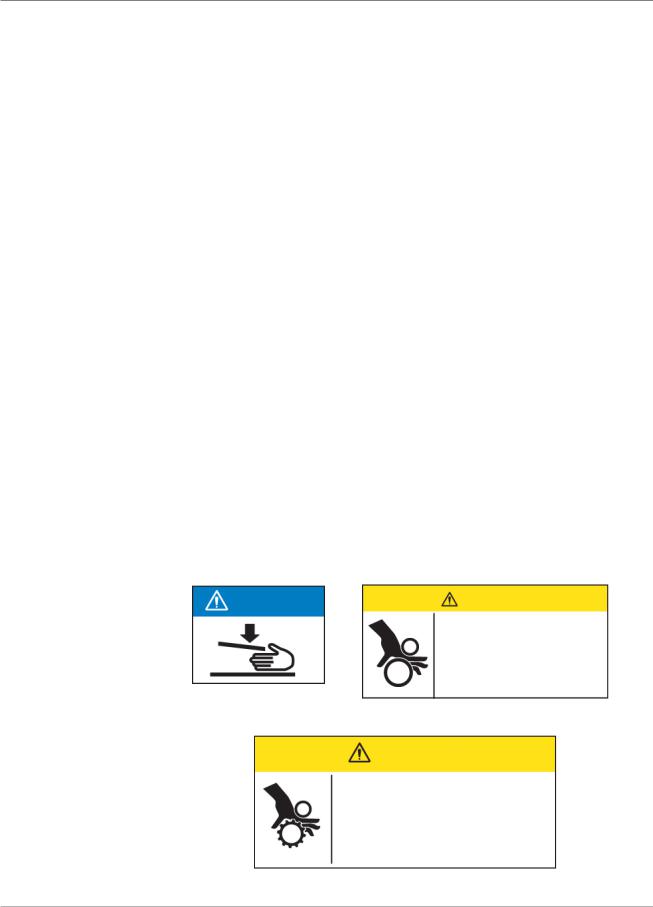
Warning Labels
•To obtain supplies and/or Material Safety Data Sheets, contact your system supplier. Refer to the Contact Information List at the front of this guide for more information.
•Operation of this equipment without periodic maintenance will inhibit optimum operating performance and could cause the equipment to malfunction. Contact your system supplier for the required service schedule.
•Always follow specific occupational safety and health standards for your workplace.
•To reduce the risk of fire or electrical shock, DO NOT attempt to remove covers or disassemble the control panel or its base. The cabinet encloses hazardous parts. If you should damage the unit, contact your system supplier. Refer to the Contact Information List at the front of this guide for more information.
If your stacker has an AC adapter to power the stacker:
•Use only the AC adapter designed specifically for the stacker. Third-party AC adapters may damage the stacker.
•To protect against electrical shock, plug the AC adapter power cord into a properly grounded wall outlet.
•Do not route the AC adapter cable over sharp edges or trap it between furniture.
The following warning labels are attached to modules on the system to alert you to potential injury that could occur with careless operating procedures. These same labels will be shown throughout the manual as they apply to the various modules that are discussed in that section.
NOTICE |
CAUTION |
|
Moving mechanism can result |
|
in personal injury. |
|
Keep hands, long hair, ties, |
|
jewelry and loose clothing |
|
away from moving parts. |
CAUTION
Moving mechanism can result in personal injury.
Keep hands, long hair, ties, jewelry and loose clothing away from moving parts.
SV61311 Rev. E |
1-7 |

1 • Introduction
Book Contents |
This remaining chapters in this book contain setup, operation, troubleshoot- |
|
ing and reference information about your document inserting system. |
|
• Chapter 2, Meet the Inserting System - orients you to system software |
|
and hardware components. |
|
• Chapter 3, Basic Operation - explains basic steps for running a job. |
|
• Chapter 4, Advanced Operation - describes advanced procedures. |
|
• Chapter 5, Troubleshooting - explains screen adjustment procedures, |
|
lists errors and their corrective actions, and describes routine mainte- |
|
nance procedures. |
|
• Chapter 6, Reference - lists system specifications. |
|
• Chapter 7, Add-On Modules - provides a brief description of each add- |
|
on module. |
|
• Chapter 8, Scanning - explains scanning options. |
|
• Appendix A, Glossary - contains definitions for commonly used terms, |
|
and explanations of the icons you'll see on the display screen. |
|
|
|
NOTE: Machine Keys will appear in all capital letters. Option Keys will appear in |
|
Initial Caps in quotes ("). Variables within options will appear in quotes (") and in |
|
the same case as shown on the screen. |
|
|
1-8 |
SV61311 Rev. E |

2 • Meet the Inserting
System
System Components.................................................................... |
2-2 |
Feeder Tower............................................................................... |
2-4 |
Feeder Trays................................................................................ |
2-5 |
Sheet Trays............................................................................ |
2-5 |
Insert Trays............................................................................ |
2-6 |
Manual Feeder............................................................................. |
2-7 |
Transport Deck............................................................................. |
2-8 |
Mail Piece Path...................................................................... |
2-8 |
Pre-fold Accumulator.............................................................. |
2-8 |
Folder..................................................................................... |
2-9 |
Post-fold Accumulator ........................................................... |
2-9 |
Insertion Area......................................................................... |
2-9 |
Folder Bypass Path................................................................ |
2-9 |
Moistener, Closer, Sealer....................................................... |
2-9 |
About the Control Panel............................................................. |
2-10 |
Screen Option Keys............................................................. |
2-10 |
Fixed Function Keys.............................................................. |
2-11 |
Machine Action Keys............................................................ |
2-13 |
Screen Navigation Keys....................................................... |
2-13 |
Display Screen........................................................................... |
2-14 |
Header Area......................................................................... |
2-14 |
Status Area........................................................................... |
2-15 |
Access Rights............................................................................ |
2-20 |
Logging In............................................................................ |
2-21 |
Logging Out.......................................................................... |
2-21 |
About System Covers................................................................ |
2-22 |
Opening the Covers............................................................. |
2-23 |
Closing the Covers............................................................... |
2-23 |
About the Paper Release Knobs/Levers.................................... |
2-24 |
About Add-On Modules.............................................................. |
2-24 |
SV61311 Rev. E |
2-1 |
2 • Meet the Inserting System
System
Components
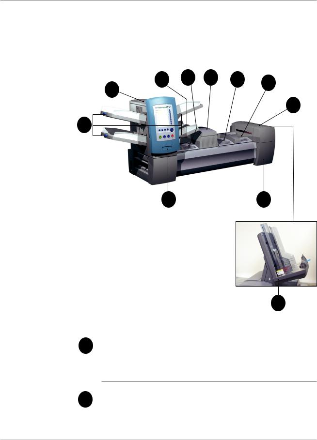
The base system configuration includes a Feeder Tower, Transport Deck, and Envelope Sealer; the DI950 features an additional integrated High Capacity Envelope Feeder. Additional modules can be added to utilize the full potential of the system.
3 |
4 |
5 |
6 |
7 |
2 |
|
|
|
|
|
|
|
|
8
1
10 |
9 |
Figure 2.1: The DI900 System
|
11 |
|
|
|
DI950 only |
1 |
Feeder Tower Trays - feed sheets or inserts to the Feeder Tower. |
|
|
|
|
NOTE: If enabled, the lower left Tray is assigned with the letter "A" on the Mail Piece Icon Tree. When a High Capacity Envelope Feeder is not part of the system configuration, this Tray is the primary Tray for feeding envelopes designated for a given job.
2 |
Feeder Tower - is a two-sided Tray holder/material feeder. |
|
2-2 |
SV61311 Rev. E |
Meet the Inserting System • 2
System Components (continued)
3Manual Feeder - allows you to manually feed stapled or unstapled sets of up to 5 sheets of 20 lb (80gsm) paper. The machine waits for each set to be manually fed before folding and inserting the set automatically into the envelope. The Manual Feed option is available during job creation. Inserts and/or Sheets from other Trays can also be added to the job.
4Pre-fold Accumulator - is a staging area for the material that needs to be collated together and then sent to the Folder unit.
5Folder - applies one of the available fold types to Sheets.
6Post-fold Accumulator - is a staging area for the folded Sheets to meet any inserts that are to be included.
Insertion Area - is the part of the transport where the collation in-
7tended for a single addressee is inserted into an outer envelope.
8Moistener, Closer, Sealer - Brushes sweep across the envelope flap to wet the glued area of the flap. The letter-size envelope then moves through the Closer and Sealer areas of the unit to complete the mail piece.
9Sealing Solution Bottle - is located inside an opening cover at the front right side of the machine. It provides sealing solution to the envelope sealing system.
10Control Panel - allows you to run the machine and configure job settings. It also displays the machine status and shows loading instructions and details of the job. See the following pages for more information on the controls and screen.
11High Capacity Envelope Feeder (DI950 only) - holds at least 500 letter-sized envelopes. It feeds directly to the Insertion Area.
Drop Stacker (available on all units, not illustrated) or Power Stacker (Optional, not illustrated) - collects and neatly stacks the finished mail pieces that exit the system. The drop stacker can be unlatched from the system when it is not needed. The power stacker is mounted to the system.
SV61311 Rev. E |
2-3 |

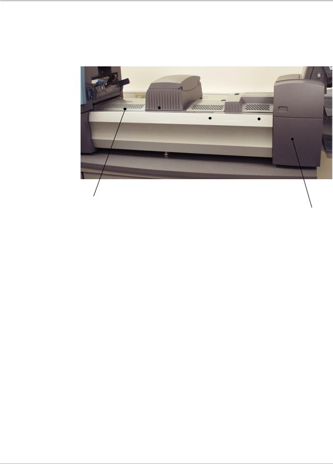
2 • Meet the Inserting System
Feeder Tower |
The Feeder Tower is a two-sided Tray holder/material feeder that stands at |
|
one end of the unit. Unlocking a latch on the left side of the Tower opens it to |
|
expose Feeder Exit and Tower Transport Rollers. This makes it easy to ac- |
|
cess media that may stop as it exits the Tower. Depending on the Configura- |
|
tion, the Tower accepts two or four Feeder Trays. |
CAUTION
Moving mechanism can result in personal injury.
Keep hands, long hair, ties, jewelry and loose clothing away from moving parts.
Push latch up to open Tower cover
Figure 2.2.1: Latch Opens Feeder Tower.
Figure 2.2.2: Two-sided Feeder Tower: Open for easy access to Feed Rollers.
2-4 |
SV61311 Rev. E |
Meet the Inserting System • 2
Feeder Trays
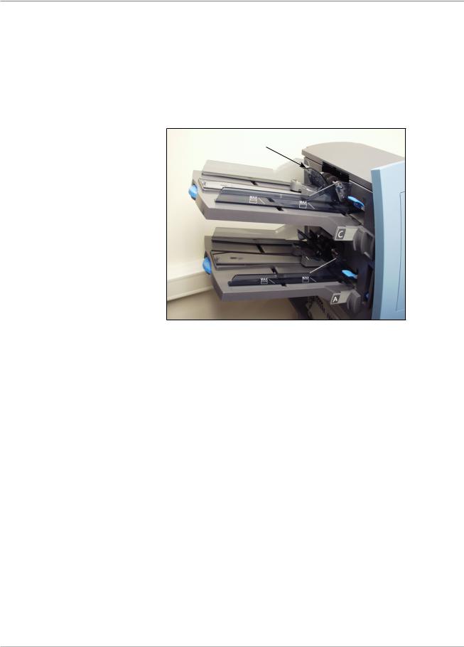
Sheet Trays
There are two types of Feeder Trays:
•Sheet Trays
•Insert Trays
The required Tray type is based on the type of material selected for a given job.
Sheet Trays feed flat, unfolded material. Use only the recommended materials. Refer to the specifications in Chapter 6.
NOTE: Sheet Trays have fill marks on their side walls. Be sure to keep your stack of materials at or below these marks to avoid feed problems.
Figure 2.3.1: Sheet Trays
SV61311 Rev. E |
2-5 |
2 • Meet the Inserting System
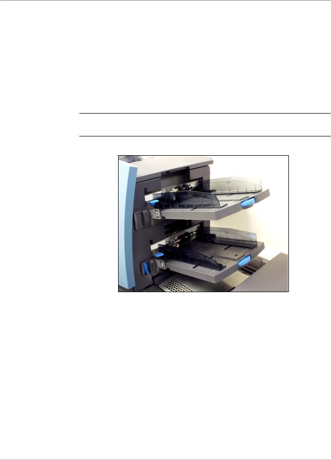
Insert Trays
Insert Trays feed items that do not need folding (envelopes, cards, booklets, slips and pre-folded media) into the system. Insert Trays have a weighted sliding mechanism known as a Sled that keeps pressure on the material for proper feeding.
Insert Trays have two sets of maximum fill lines: one set for slips, and a second set for envelopes.
Sled mechanism
Figure 2.3.2: Insert Tray
2-6 |
SV61311 Rev. E |
Meet the Inserting System • 2
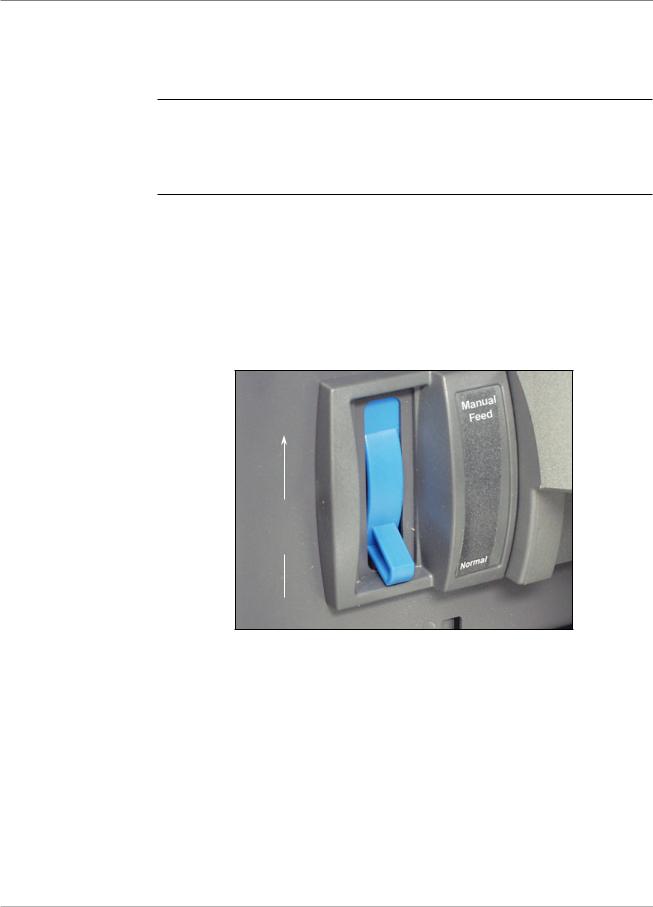
Manual Feeder Use the Manual Feeder to hand feed stapled or unstapled sets of up to five sheets. The machine waits for each set to be manually fed before folding
and inserting the set into the envelope.
NOTES:
•The feeder type of the item (to be fed manually) in the current job has to be defined as Manual for the feature to work.
•The job with the manual fed piece can also include items from other feeders, including sheets or inserts.
To use the Manual Feeder:
1.Select a job that uses the Manual Feeder.
2.Push the Manual Feed lever up.
3.Press TRIAL PIECE to start the machine.
4.Feed each set by pushing the edge into the rollers one at a time.
5.Push the lever down when you are done.
Push the Manual Feed lever up.
Figure 2.4: Manual Feed Lever.
SV61311 Rev. E |
2-7 |
2 • Meet the Inserting System
Transport Deck |
The Transport Deck accepts material from the Feeder Tower and moves it |
|
through the various modules to produce a finished mail piece. The Standard |
|
Transport Deck consists of the following: |
|
|
|
|
|
|
|
|
|
|
|
|
|
|
|
|
|
|
|
|
|
|
|
|
|
|
|
|
Pre-fold |
Folder |
|
|
|
|
|
Accumulator |
|
Post-fold |
Insertion |
Moistener, |
||
|
|
|||||
|
|
Accumulator |
Area |
Closer, |
||
|
|
|
|
|
|
Sealer |
Figure 2.5: Transport Deck
Mail Piece Path |
Material from the Feeder Trays comes down the Feeder Tower in a pre-de- |
|
fined order. Material moves rapidly from one station to the next in the Trans- |
|
port Deck to produce a finished mail piece that is dropped into a stacking |
|
bin or onto an optional high capacity output stacker. A brief description of the |
|
function of each module in the paper path is presented next. |
Pre-fold
Accumulator
The Pre-fold Accumulator is the first stop in the paper path. The Pre-fold Accumulator is a stacking place for the material that needs to be collated and folded. When the appropriate components for one mail piece finish collating on the Pre-fold Accumulator, they move into the Folder.
2-8 |
SV61311 Rev. E |

Meet the Inserting System • 2
Folder
Post-fold
Accumulator
Insertion Area
Folder Bypass
Path
Moistener,
Closer, Sealer
The stack of collated sheets exits the Pre-fold Accumulator into the Folder. The Folder then applies a fold to the stack and sends it to the Post-fold Accumulator. The Folder offers these options:
•C Fold,
•Z Fold,
•Single Fold,
•Double Fold, and
•No Fold.
An optional Inverter may be used for some address location/fold type combinations.
The accumulation of folded sheets exits the Folder onto the Post-fold Accumulator area. Other components of the mail piece, such as a Business Reply Envelope or a pre-folded insert, are added to the accumulation in the Post-fold Accumulator area. When all components are present, the stack moves to the Insertion Area.
The contents of the mail piece meet the outer envelope at the Insertion Area. The envelope arrives at the Insertion Area with its front face down and flap open. Envelope Openers on the Insertion Area open the envelope wide enough to allow the contents to be slid inside.
The outer envelope, fed from the Feeder, that will contain the collated media runs through the bottom part of the Transport Deck. The route this envelope travels is known as the Folder Bypass Path.
As the envelope passes over the Moistener, brushes sweep across the top of the flap to wet the glued area of the flap. The envelope is then inverted and slid through the Closer and Sealer portion of the system to complete the mail piece. From there, the mail piece is dropped onto a stacker.
SV61311 Rev. E |
2-9 |
2 • Meet the Inserting System
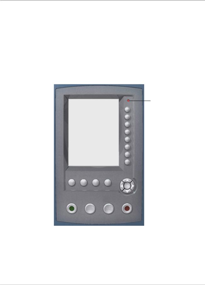
About the
Control Panel
The Control Panel consists of the following components:
•Screen Option Keys allow you to define settings for up to 24 jobs that you can store in the system’s memory. These keys also provide the means to edit any of the stored jobs.
•Fixed Function Keys allow you to access the system’s built-in tools that appear on the screen (such as the system’s help file).
•Screen Navigation Keys allow you to move UP/DOWN and right/left in the Display and to apply selections that you’ve made.
•Machine Action Keys control hardware components and mechanical movements.
•LED Status Indicator
Screen Option
Keys
LED Status Indicator
|
|
|
|
|
|
|
|
|
|
|
Screen Option Keys |
|
|
|
|
|
|
|
|
|
|||
|
|
|
|
|
|
|
|
|
|
Fixed Function Keys |
|
|
|
|
|
|
|
|
|
|
|
||
|
Reset |
|
|
|
|
|
|
||||
|
Counter |
Help Cancel |
Home |
|
|
|
|
|
|
|
|
|
|
|
|
|
OK |
|
|
|
|
|
Screen Navigation Keys |
|
|
|
|
|
|
|
|
|
|||
|
|
|
|
|
|
|
|
|
|
|
|
|
Start |
Trial |
Clear |
Stop |
|
|
|
|
|
|
|
|
Piece |
Deck |
|
|
|
|
|
Machine Action Keys |
|||
|
|
|
|
|
|
|
|
|
|
|
|
|
|
|
|
|
|
|
|
|
|
|
|
|
|
|
|
|
|
|
|
|
|
|
|
Control Panel
The Screen Option Keys are the eight keys on the right side of the screen. These keys correspond to options on the screen, and therefore have no dedicated labels. Use these keys to highlight an item in a displayed pick list and/or to select the associated menu, item, action, or option.
2-10 |
SV61311 Rev. E |
Meet the Inserting System • 2
Fixed Function
Keys
The Fixed Function Keys are the top row of keys under the screen. Each of these keys has an assigned function that is enabled or disabled based on the screen that displays. Use of each of these keys is explained next in more detail.
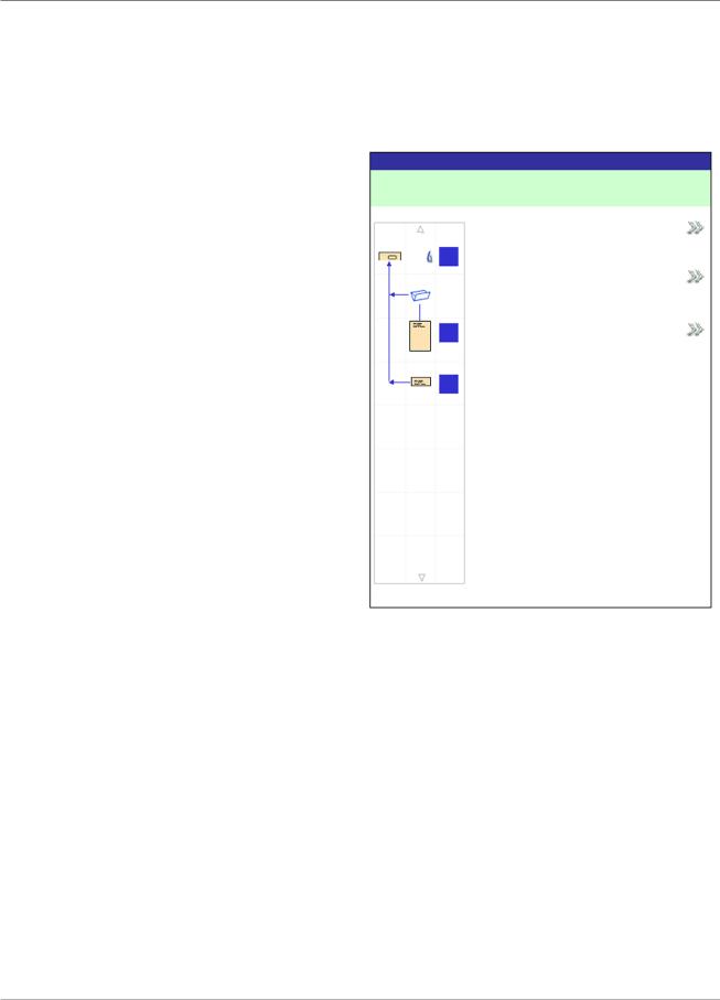
Reset Counters |
Reset Counters |
Job: ABC |
||
The system has two |
|
|
||
counters: |
Job Items |
|
||
• |
Piece Counter |
Piece Count |
||
|
||||
• |
Batch Counter |
|
||
A |
|
|||
|
|
Batch Count |
||
|
|
|
||
|
|
B |
Both |
|
|
|
D |
|
|
Reset Counters Screen
Resetting the Piece Counter
The Piece Counter appears in the bottom portion of the Display screen. It is a cumulative counter, i.e., it increments for each completed mail piece.
If you run the same job but for a different customer and/or use different materials, you'll need to zero the counter and ready it for counting the completed mail pieces in the new run.
To reset the Piece Counter:
1.Press RESET COUNTERS to display the Reset Counters screen.
2.Select "Piece Count".
3.You will be returned to the Home screen. The Piece Counter at the bottom of the screen will read "0".
SV61311 Rev. E |
2-11 |

2 • Meet the Inserting System
Fixed Function
Keys (continued)
Resetting the Batch Counter
The Batch Counter counts up to a set number. It increments one count for each completed mail piece that the system detects. The system stops when it reaches the batch count.
To reset the desired number for the job you are running:
1.Press RESET COUNTERS to display the Reset Counters screen.
2.Select "Batch Count".
3.You will be returned to the Home screen. The Batch Counter at the bottom of the screen will return to its original setting.
NOTE: The original setting for the Batch Counter cannot be less than “5” or greater than “9999”.
Resetting Both Counters
The Reset Both selection allows you to reset both the Piece Counter and the Batch Counter to zero.
1.Press RESET COUNTERS to display the Reset Counters screen.
2.Select "Both".
3.You will be returned to the Home screen. The Piece Counter at the bottom of the screen will read "0" and the Batch Counter will return to its original setting.
Help
Select "Help" for information about the screen that currently displays and for access to the entire Help file.
Cancel
Select "Cancel" to return to the previous screen.
NOTE: If you made changes to a job before pressing "Cancel", you are prompted to save the changes. Press "Yes" to save the changes; press "No" to delete the changes and to return to the last screen in which you saved changes. Be aware that once you delete the changes, they are permanently gone.
Home
Select "HOME" to return to the Home screen for the current job. The current job will automatically include any changes made while editing the job. Although the job can be run now, the changes are not saved until you choose "Save Job" from the menu. Jobs that have been changed but not saved have an asterisk next to the job name at the top of the Home screen.
2-12 |
SV61311 Rev. E |
Loading...