


 Loading...
Pitco Solstice and Solstice Supreme High Efficiency Gas Fryers
Notice
In the event of problems or questions about your order, contact the Pitco Frialator factory at (603) 225-6684.
In the event of problems or questions about your equipment, contact the Pitco Frialator Authorized Service and Parts representative (ASAP) covering your area, or contact Pitco at the numbers listed above.
MAILING ADDRESS
Pitco Frialator
P.O. Box 501
Concord, NH 03302-0501
SHIPPING ADDRESS
Pitco Frialator
10 Ferry Street
Concord, NH 03301
EQUIPMENT REFERENECE INFORMATION
Model #: __________________________
Serial #: __________________________
Date Purchased: ___________________
SG/SSH Series Service Manual |
2 |

Pitco Solstice and Solstice Supreme High Efficiency Gas Fryers |
|
Table of Contents |
|
Theory of Operation .................................................................................................... |
6 |
Fryer Components Operation.............................................................................................................. |
7 |
Heating System ................................................................................................................................... |
7 |
Safety System...................................................................................................................................... |
8 |
Filter System ....................................................................................................................................... |
8 |
Optional Basket Lift............................................................................................................................ |
8 |
Controller Operational Modes ............................................................................................................ |
9 |
Serial Numbers.................................................................................................................................. |
10 |
24V Model ................................................................................................................. |
11 |
Accessing Fryer for Servicing............................................................................................................ |
12 |
Cleaning the Gas Valve Vent Tube ................................................................................................... |
13 |
Checking the Burner Manifold Gas Pressure .................................................................................. |
14 |
Taking a Supply Gas Pressure Reading ............................................................................................ |
14 |
Removing Solid State Thermostat (If Necessary) ............................................................................ |
16 |
Taking a Manifold Gas Pressure Reading ........................................................................................ |
17 |
Adjusting Manifold Gas Pressure ..................................................................................................... |
18 |
Adjusting Pilot Pressure.................................................................................................................... |
18 |
Calibrating Solid State Thermostat................................................................................................... |
19 |
Replacing the Controllers and Wiring Harness............................................................................... |
20 |
Removing the Controller Front Panel Bezel..................................................................................... |
20 |
Removing the Solid State Wiring Harness ....................................................................................... |
21 |
Replacing the Relay Board and Paper.............................................................................................. |
23 |
Replacing the Ignition Module .......................................................................................................... |
24 |
Replacing the Spinal Tap ................................................................................................................... |
25 |
Replacing an Igniter/Pilot Assembly................................................................................................. |
28 |
Replacing the Self-Cleaning Burner Solenoid.................................................................................. |
30 |
Replacing the Gas Valve..................................................................................................................... |
31 |
Replacing the Transformer Box ........................................................................................................ |
33 |
Replacing the DVI Switch .................................................................................................................. |
35 |
Replacing the Burner Assembly ........................................................................................................ |
36 |
Replacing the Burner(s) .................................................................................................................... |
36 |
Replacing the Burner Assembly ....................................................................................................... |
38 |
Replacing the Frypot .......................................................................................................................... |
40 |
Replacing the Basket Lift Components............................................................................................. |
44 |
Removing the Basket Lift Cover ...................................................................................................... |
44 |
Replacing the Transformer ............................................................................................................... |
44 |
Replacing the Basket Lift Driver Board ........................................................................................... |
45 |
Adjusting the Magnetic Sensor......................................................................................................... |
46 |
Replacing the Basket Lift Actuator................................................................................................... |
46 |
Gas Conversion ................................................................................................................................... |
49 |
SG/SSH Series Service Manual |
3 |
Pitco Solstice and Solstice Supreme High Efficiency Gas Fryers |
|
mV Model.................................................................................................................. |
50 |
Accessing Fryer for Servicing............................................................................................................ |
51 |
Cleaning the Gas Valve Vent Tube ................................................................................................... |
51 |
Checking the Burner Manifold Gas Pressure .................................................................................. |
51 |
Taking an Incoming Supply Gas Pressure Reading.......................................................................... |
51 |
Taking a Manifold Gas Pressure Reading ........................................................................................ |
52 |
Adjusting Manifold Gas Pressure ..................................................................................................... |
53 |
Measuring Thermopile ....................................................................................................................... |
54 |
Taking a Millivolt Reading............................................................................................................... |
54 |
Adjusting the Thermopile ................................................................................................................. |
54 |
Replacing the Thermostat .................................................................................................................. |
55 |
Calibrating the Thermostat ............................................................................................................... |
57 |
Replacing the Hi-Limit Thermostat.................................................................................................. |
58 |
Filter System.............................................................................................................. |
59 |
Replacing the Return Valve ............................................................................................................... |
60 |
Replacing the Flush Hose Assembly and Valve ............................................................................... |
61 |
Replacing the Heat Tape .................................................................................................................... |
64 |
Replacing the Waste Oil and Components ....................................................................................... |
65 |
Removing Rear Mounting Bracket ................................................................................................... |
65 |
Removing the Check Valve .............................................................................................................. |
66 |
Replacing the Filter Pump and Motor.............................................................................................. |
68 |
Removing the Filter Pump and Motor .............................................................................................. |
68 |
Replacing Seal Kit ............................................................................................................................ |
70 |
Removing the Filter Pump from the Motor ...................................................................................... |
71 |
Replacing the Return Switch ............................................................................................................. |
72 |
Replacing the Drain Line or Gasket.................................................................................................. |
74 |
Replacing the Pump Relay and Circuit Breaker ............................................................................. |
75 |
Replacing the Circuit Breaker........................................................................................................... |
75 |
Replacing the Pump Relay................................................................................................................ |
76 |
Troubleshooting and Problem Isolation .................................................................... |
77 |
Troubleshooting and Problem Isolation ........................................................................................... |
78 |
Interpretation of Solid State Controller Lights ................................................................................. |
78 |
Solid State Thermostat Field Calibration.......................................................................................... |
79 |
Component Troubleshooting ............................................................................................................. |
80 |
Probe ................................................................................................................................................. |
80 |
Roll Out Switch................................................................................................................................. |
80 |
Gas Valve.......................................................................................................................................... |
80 |
Hi-Limit ............................................................................................................................................ |
80 |
Drain Valve and Return Valve Switches .......................................................................................... |
81 |
Transformer....................................................................................................................................... |
81 |
Ignition Module ................................................................................................................................ |
81 |
Relay Board ...................................................................................................................................... |
82 |
Computer Control ............................................................................................................................. |
82 |
SG/SSH Series Service Manual |
4 |
Pitco Solstice and Solstice Supreme High Efficiency Gas Fryers |
|
Digital Solid State Control................................................................................................................ |
83 |
Primary Solid State Control.............................................................................................................. |
83 |
Backup Solid State Control............................................................................................................... |
84 |
Optional Basket Lift.......................................................................................................................... |
84 |
Probe Resistance Chart ..................................................................................................................... |
85 |
Orifice Size Chart ............................................................................................................................. |
86 |
Orifice Size at Sea Level Chart......................................................................................................... |
87 |
Wiring Diagrams ........................................................................................................ |
88 |
Simplified Wiring Diagrams .............................................................................................................. |
89 |
Wiring Diagram – Full Vat with SCB .............................................................................................. |
89 |
Wiring Diagram – Twin Vat with SCB ............................................................................................ |
90 |
Wiring Diagram – Basket Lifts......................................................................................................... |
91 |
Wiring Diagram – Filter Motor 115V-60Hz..................................................................................... |
92 |
Wiring Diagrams – Filter Motor 208-240V...................................................................................... |
93 |
SG/SSH Series Service Manual |
5 |
Pitco Solstice and Solstice Supreme High Efficiency Gas Fryers
Theory of Operation
SG/SSH Series Service Manual |
6 |

Pitco Solstice and Solstice Supreme High Efficiency Gas Fryers
Fryer Components Operation
The SG and SSH fryer components function in specific order of operation. Knowing and understanding the sequence of fryer and components operation enables you to diagnose equipment failure more accurately.
Heating System
The unit is connected to line voltage:
If Fuse F1 on the relay board is good:
The A.C. indicator is illuminated.
The controller is supplied with 24 VAC.
With the drain valve handle closed, the proximity switch supplies 24 VAC to the drain valve interlock (DVI) input at the controller.
24 VAC is at the Side On (SO). relay COM contact.
The controller is turned ON:
The SO indicator on the relay board is illuminated.
The SO relay is energized, closing the circuit.
With the roll out switch and hi-limit in the closed position, the ignition module receives 24VAC at terminal 6 (24 VAC).
The ignition module:
Sends 24 VAC from terminal 3(PV) to the PV terminal on the gas valve.
Sends the igniter 15kv to spark.
Senses the flame once the pilot has lit and it sends 24 VAC at terminal 1(MV) and puts 24 VAC at the Heat Demand (HD) relay COM contact on the relay board. The HD relay on the relay board interrupts the 24 VAC supply to the gas valve until the controller calls for heat.
NOTE: When the controller is on, the pilot should always remain lit.
The controller calls for heat:
The HD indicator on the relay board is illuminated.
The HD relay is energized, closing the circuit sending 24 VAC to the MV terminal on the gas valve.
The computer is supplied with a 24 VAC heat feedback (HFB) signal.
SG/SSH Series Service Manual |
7 |

Pitco Solstice and Solstice Supreme High Efficiency Gas Fryers
Safety System
When the roll out switch or hi-limit trips, it interrupts the 24 VAC supply to the ignition module.
When the controller calls for heat, it does not receive a 24 VAC HFB. With approximately 90 seconds of HFB loss, the controller indicates an ignition failure or heat failure.
After the roll out switch hi-limit is reset, turn the controller off and then back on for the unit to heat.
Filter System
Opening the RED return valve handle:
Opens the return valve to that vat.
Closes the pump proximity switch causing the “pump run” relay to be energized.
The pump motor begins to run.
Closing the return valve handle de-energizes the relay and the pump motor stops running and the return valve closes.
The pump system is equipped with a circuit breaker which de-energizes the system and the heat tape in the event of over current. The circuit breaker must be in the “ON” position for the pump and heat tape to operate.
NOTE: Circuit Breaker should remain in the “ON” position at all times.
The return piping system may be provided with optional heat tape to prevent solidification of solid shortening. The heat tape is low wattage and is on constantly to maintain liquid shortening in the line.
Optional Basket Lift
The basket lift is a self contained unit that requires a 120V, 208V, or 240V supply. With most fryer configurations, the power is supplied from the entrance box at the back of the fryer, but some configurations require power directly from a wall outlet.
When power is supplied to basket lift assembly, the baskets lift to the up position.
The baskets lower with a 24 VDC output from the controller.
The basket lift control voltage is supplied from the controller
The basket lift operational voltage is supplied from the line voltage supply that powers the transformer in the basket lift assembly.
SG/SSH Series Service Manual |
8 |

Pitco Solstice and Solstice Supreme High Efficiency Gas Fryers
Controller Operational Modes
|
|
|
|
|
|
|
TEMPERATURE |
|
MODE |
ENTRY |
|
INDICATION |
SET POINT |
EXIT |
|||
BOIL |
With control initially off, toggle |
|
Power and HD |
|
|
Fixed at 200°F |
Press OFF to |
|
OUT |
the ON/OFF switch: |
|
indicators are on. HFB |
(93°C) |
exit. |
|||
|
ON – OFF – |
|
indicator flashes at 0.5 |
|
|
|||
|
|
seconds rate until exit. |
|
|
||||
|
ON – OFF – Then ON |
|
|
|
||||
|
|
|
|
|
|
|
|
|
|
This sequence must be |
|
|
|
|
|
|
|
|
performed within 3 seconds. |
|
|
|
|
|
|
|
MELT |
Select MELT and then press |
|
Same as below except |
No set point. HD is |
Automatic |
|||
|
ON. |
|
fixed heat cycle. |
suppressed if Vat is |
switch to |
|||
|
Melt may be bypassed by |
|
|
|
|
|
greater than 250°F |
COOK after |
|
|
|
|
|
|
(121°C). |
temperature is |
|
|
pressing COOK. |
|
|
ON |
OFF |
|||
|
|
|
|
greater than |
||||
|
|
|
|
|
|
|
|
|
|
|
|
GAS |
8 sec |
22 sec |
|
140°F (60°C) |
|
|
|
|
ELEC |
4 sec |
26 sec |
|
or press OFF |
|
|
|
|
|
to exit. |
||||
|
|
|
|
|
|
|
|
|
COOK |
Press COOK and then press |
|
Power indicator is on. |
Knob setting |
Press OFF to |
|||
|
ON. |
|
HD as required to |
|
exit. |
|||
|
Automatic entry after |
|
maintain Vat |
|
|
|
|
|
|
|
temperature. HFB |
|
|
||||
|
completed MELT cycle. |
|
|
|
||||
|
|
indicator follows HD. |
|
|
||||
|
|
|
|
|
||||
SG/SSH Series Service Manual |
9 |
Pitco Solstice and Solstice Supreme High Efficiency Gas Fryers
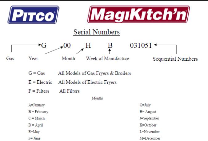
Serial Numbers
SG/SSH Series Service Manual |
10 |
Pitco Solstice and Solstice Supreme High Efficiency Gas Fryers
24V Model
SG/SSH Series Service Manual |
11 |
Pitco Solstice and Solstice Supreme High Efficiency Gas Fryers
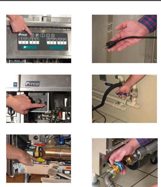
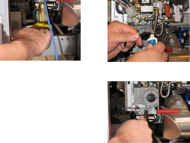
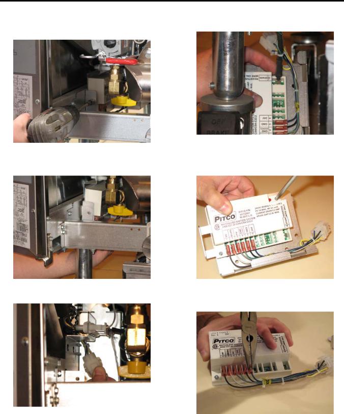
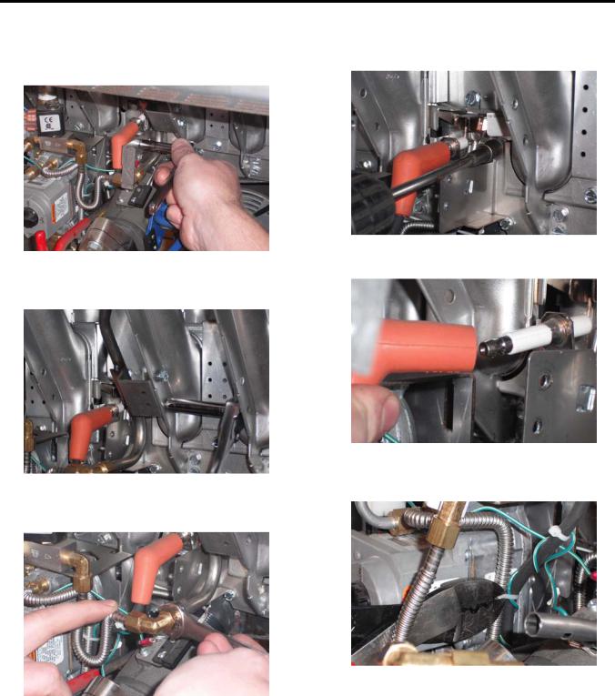
Accessing Fryer for Servicing
1. Press off button on control panel. |
4. Unplug all power cords. |
2. Slide button to solid state. |
5. Shut off the main gas supply line to the unit. |
3. Shut off the individual gas supply line.
6.Pull back collar to remove the quick disconnect gas line.
SG/SSH Series Service Manual |
12 |
Pitco Solstice and Solstice Supreme High Efficiency Gas Fryers
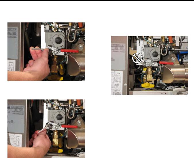
Cleaning the Gas Valve Vent Tube
1.Bend the gas valve vent tube to allow for removal.
3.Clean the tube (not shown) and reinstall.
NOTE: Make sure the vent tube is not reinstalled in an upright position and there are no kinks in the tube.
2.Loosen nut at the base of the vent tube with a 3/8 inch open-ended wrench and then remove.
SG/SSH Series Service Manual |
13 |
Pitco Solstice and Solstice Supreme High Efficiency Gas Fryers
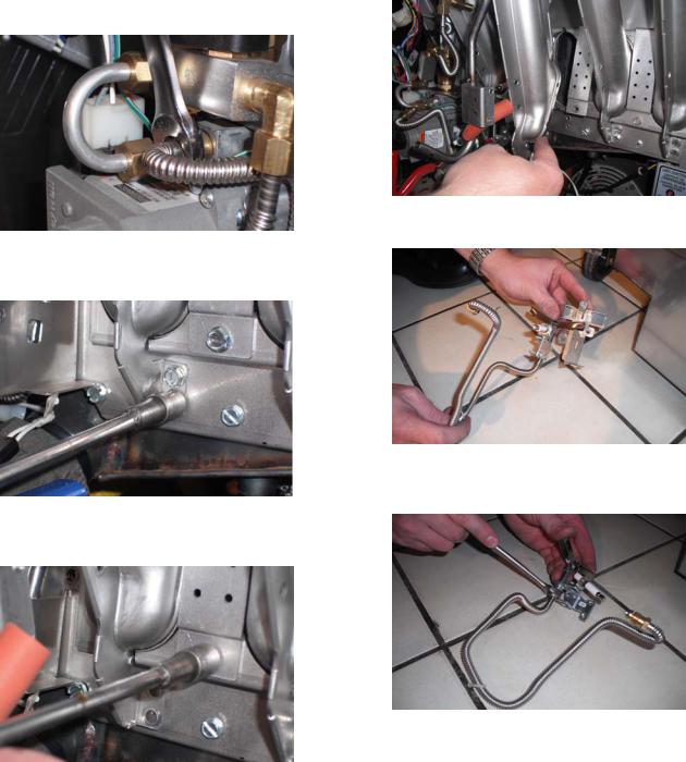
Checking the Burner Manifold Gas Pressure
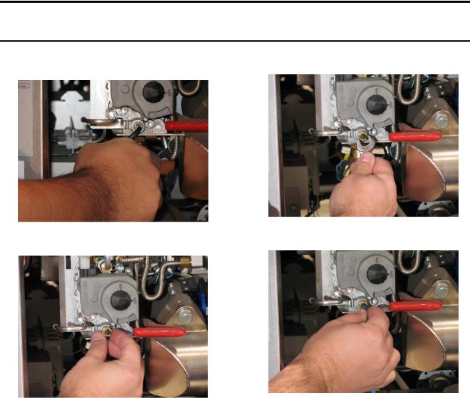
Taking a Supply Gas Pressure Reading
1.Unscrew and remove the gas supply plug with a 3/16 inch hex wrench.
3.Finish tightening the test fitting using a 7/16 inch open-ended wrench.
2. Finger tighten the test fitting into the test port. |
4. Connect the manometer. |
|
SG/SSH Series Service Manual |
14 |
Pitco Solstice and Solstice Supreme High Efficiency Gas Fryers
5. Turn on the main gas supply line.
6. Check the supply gas pressure with the manometer and compare the reading to the supply gas pressure table to determine what the incoming gas pressure should be.
Supply Pressure Table
|
NAT |
|
LP |
|
|
|
|
|
7 to 9 |
|
11 to 13 |
|
|
|
|
|
NOTE: You cannot adjust the supply gas |
||
|
pressure at the unit. Anything |
||
|
over/under the recommended |
||
|
amount should be adjusted at the |
||
|
facility’s main gas line. |
||
7. |
Shut off the main gas supply line. |
||
8. |
Disconnect the manometer. |
|
|
9. |
Remove the test fitting. |
|
|
10. Apply Teflon paste to gas supply plug.
11.Reinstall gas supply plug with a 3/16 inch hex wrench.
12. Turn on the main gas supply line.
SG/SSH Series Service Manual |
15 |
Pitco Solstice and Solstice Supreme High Efficiency Gas Fryers
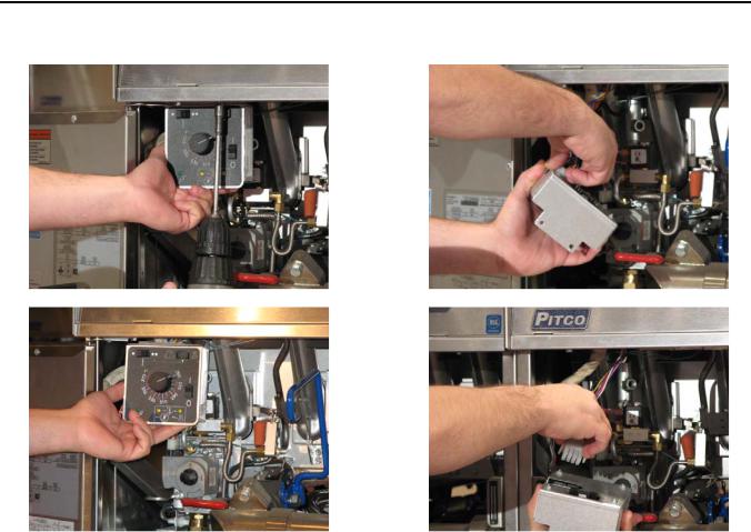
Removing Solid State Thermostat (If Necessary)
1.Remove the two (2) screws, which hold the solid state thermostat, with a 5/16 inch socket.
2.Disconnect solid state thermostat control harness.
SG/SSH Series Service Manual |
16 |
Pitco Solstice and Solstice Supreme High Efficiency Gas Fryers
Taking a Manifold Gas Pressure Reading
1.Unscrew and remove the gas manifold plug with a 3/16 inch hex wrench.
3.Finish tightening the test fitting using a 7/16 inch open-ended wrench.
2. Finger tighten the test fitting into the test port. |
4. Connect the manometer. |
5. If necessary, reconnect the solid state thermostat (reverse steps for “Removing Solid Stats Thermostat” on page 16.
SG/SSH Series Service Manual |
17 |
Pitco Solstice and Solstice Supreme High Efficiency Gas Fryers
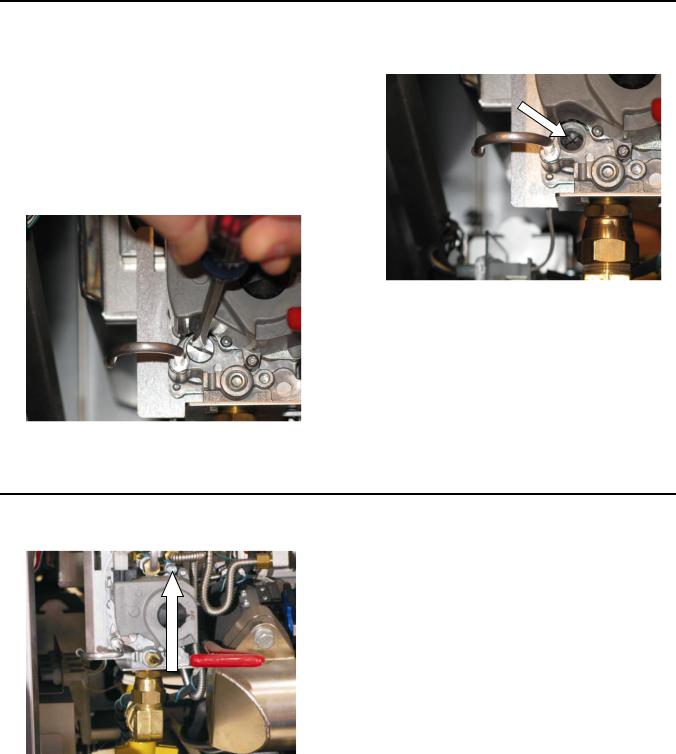
Adjusting Manifold Gas Pressure
1.Check the manifold gas pressure with the manometer and compare the reading to the manifold gas pressure table.
3.Insert flathead screwdriver into the cap and turn counter-clockwise to increase the gas pressure or clockwise to decrease the gas pressure.
Manifold Gas Pressure Table
NAT |
LP |
|
|
4.0” |
10” |
|
|
2.Insert a flathead screwdriver into the cap and turn counter-clockwise to remove it.
4. When adjustment is complete:
a. Disconnect the manometer. b. Remove the test fitting.
c. Reinstall the gas manifold plug. d. Reconnect solid state thermostat. e. Turn on gas supply line.
Adjusting Pilot Pressure
1.Remove pilot adjustment cap with Philips screwdriver.
2.Rotate adjuster clockwise to decrease and counter-clockwise to increase pilot flame.
3.Replace adjustment cap.
SG/SSH Series Service Manual |
18 |
Pitco Solstice and Solstice Supreme High Efficiency Gas Fryers
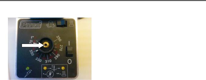
Calibrating Solid State Thermostat
1.Remove the cap of the knob with a flat head screwdriver.
2.With a 5/16 inch socket, loosen the collet.
3.Rotate the knob to point at actual temperature.
4.Tighten collet and replace knob cap.
SG/SSH Series Service Manual |
19 |
Pitco Solstice and Solstice Supreme High Efficiency Gas Fryers
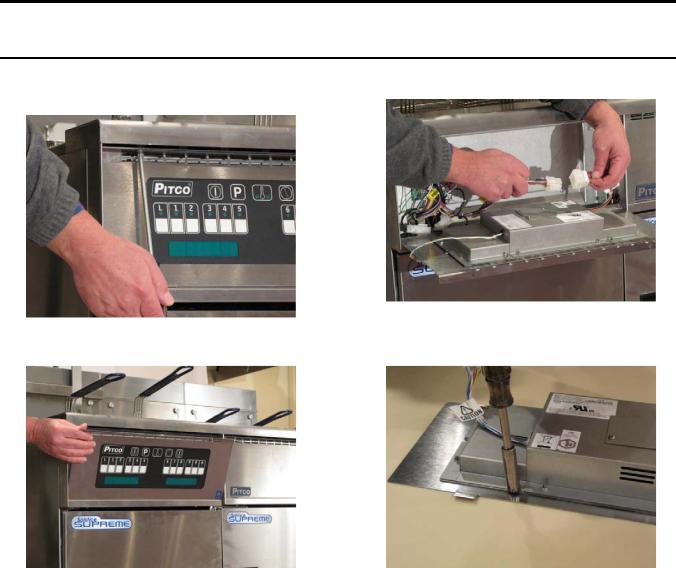
Replacing the Controllers and Wiring Harness
Removing the Controller Front Panel Bezel
1.Remove the two (2) screws on the controller panel using a Phillips screwdriver.
3. Disconnect the controller wiring harness.
2. Pull out the controller panel front bezel.
4.Remove the four (4) screws on the back side of the bezel using a 3/8 inch nut driver.
SG/SSH Series Service Manual |
20 |

Pitco Solstice and Solstice Supreme High Efficiency Gas Fryers
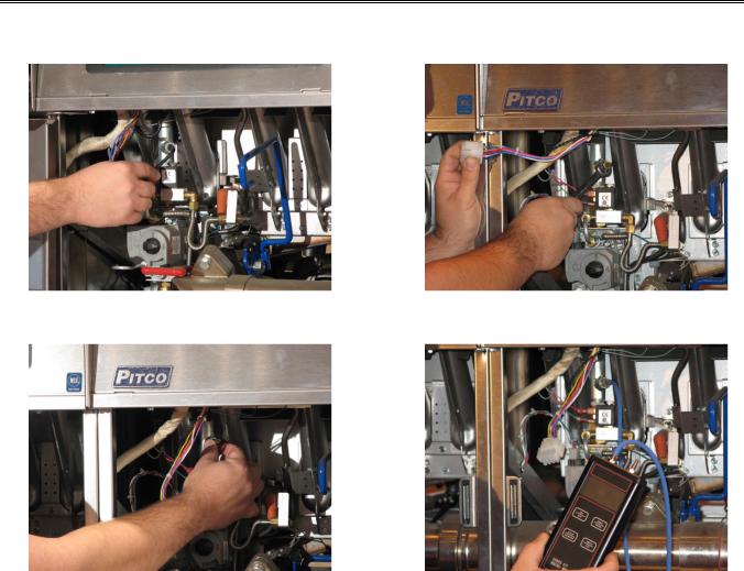
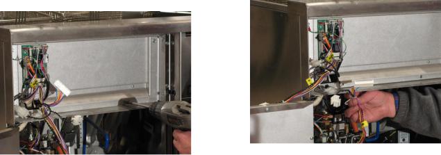
Removing the Solid State Wiring Harness
1.Remove the two (2) screws in the front panel bottom holder using a 5/16 inch socket.
3. Disconnect the probe connection (J/P43).
2.Remove the two (2) screws in the cable retainer bracket using a 5/16 inch socket.
4.Disconnect B6746601 from J/P33 on the relay board.
SG/SSH Series Service Manual |
21 |
Pitco Solstice and Solstice Supreme High Efficiency Gas Fryers |
|
5. Loosen the controller box screws using a |
6. Remove the controller wiring harness. |
5/16 inch socket. |
|
7. Replace with a new controller wiring harness following steps 1 through 6 in reverse.
SG/SSH Series Service Manual |
22 |
Pitco Solstice and Solstice Supreme High Efficiency Gas Fryers
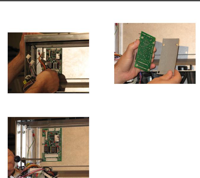
Replacing the Relay Board and Paper
1.Remove the front panel. See “Removing the Controller Front Panel Bezel” on page 20.
2.Disconnect all connections.
5.Remove the existing insulator and replace with a new insulator.
3.Remove the four (4) screws, which hold down the relay board, using a small flathead screwdriver.
NOTE: Make sure the insulator does not have puncture marks in it.
6.Reconnect all connections and reinstall the front panel.
4. Remove the relay board and flip it over.
SG/SSH Series Service Manual |
23 |
Pitco Solstice and Solstice Supreme High Efficiency Gas Fryers
Replacing the Ignition Module
1.Remove one (1) screw, which hold the ignition module, using a 5/16 inch socket.
4. Remove the ignition wire.
2.Pull the module box and bracket toward the front of the unit, and then to the right.
5.Remove the two (2) screws, which hold the module on the plate, using a Phillips screwdriver.
3. Disconnect the plug. |
6. Remove the harness pins using needle-nose |
|
pliers. |
7. Follow steps 1 through 6 in reverse.
SG/SSH Series Service Manual |
24 |
Pitco Solstice and Solstice Supreme High Efficiency Gas Fryers
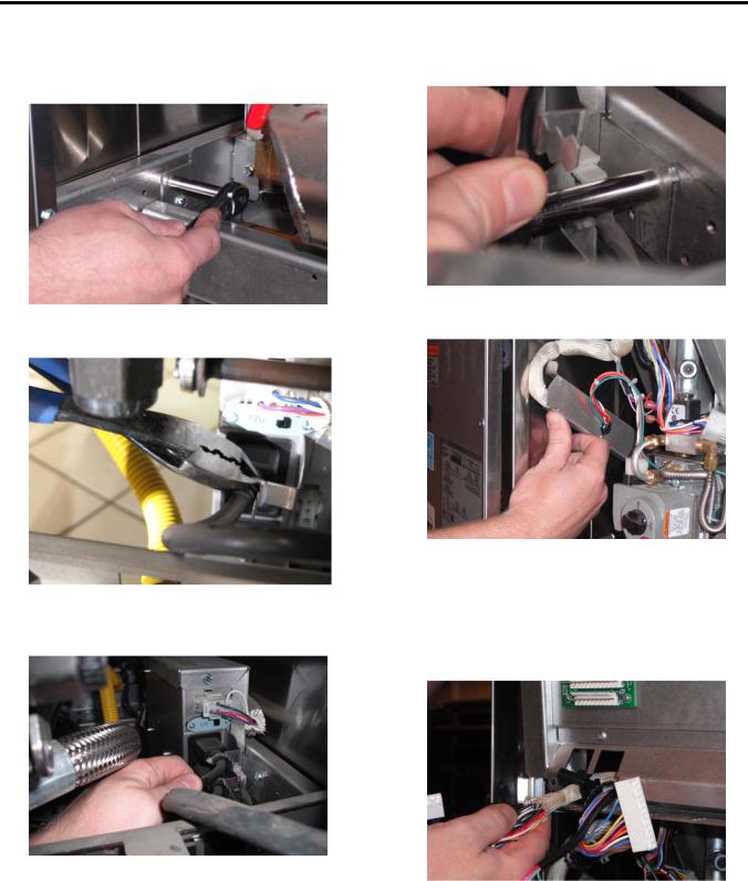
Replacing the Spinal Tap
1.Remove the two (2) screws in the front of the unit, which hold the entrance box assembly, using a 5/16 inch socket.
4.Remove the two (2) screws, which hold the spinal harness, using a /16 socket.
5. Remove the entrance box assembly.
2. Cut the zip ties from the cord retainers.
3.Unplug the cords from the electrical entrance box assembly.
6.Remove the front panel assembly. See “Replacing the Controllers and Wiring Harness” on page 20.
7.Disconnect all the connections and remove the harness from front panel.
SG/SSH Series Service Manual |
25 |
Pitco Solstice and Solstice Supreme High Efficiency Gas Fryers
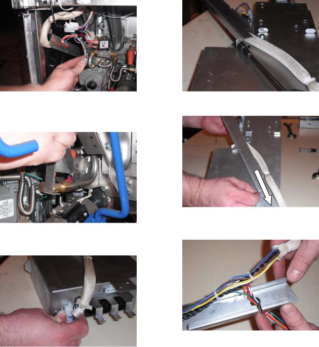
8. Disconnect the connection from the valve.
9.Remove the bolt from the pilot, which holds the ignition ground, using a 5/16 inch open-ended wrench.
10.Once the entrance box is out, disconnect the spinal tap connection.
11. Remove one (1) screw using a 5/16 inch socket.
12. Slide metal retaining bracket off.
13.Remove the spinal tap wiring harness from the grommet.
SG/SSH Series Service Manual |
26 |
Pitco Solstice and Solstice Supreme High Efficiency Gas Fryers
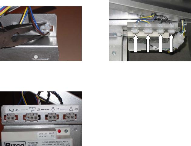
14.Disconnect J4, J5, J7, J8 plugs using needlenose pliers.
15.Make sure to connect the new plugs into the correct connector location.
Side View of Plugs
Top View of Plugs
J4 |
J5 |
J7 |
J8 |
16.Follow steps 1 through 15 in reverse to reinstall the entrance box and new spinal tap wiring harness.
SG/SSH Series Service Manual |
27 |
Pitco Solstice and Solstice Supreme High Efficiency Gas Fryers
Replacing an Igniter/Pilot Assembly
1.Remove the two (2) screws, which hold the pilot and runner tube orifice bracket, using a
5/16 inch socket.
4.Remove the two (2) screws, which hold the pilot, using a 5/16 inch socket.
5. Remove the ignition wire.
2.Remove the two (2) screws, which hold the runner tube, using a 5/16 inch socket.
6. Cut the zip ties, which hold the ignition wire to the pilot tubing.
3.Remove the runner tube orifice using a 1/2 inch open-ended wrench.
SG/SSH Series Service Manual |
28 |
Pitco Solstice and Solstice Supreme High Efficiency Gas Fryers
7.Remove the flexible line for the pilot tubing at the gas valve using a 1/2 inch open-ended wrench.
8.Remove the two (2) screws at the bottom of the left and right burner using a 5/16 inch socket.
9.Remove one (1) screw, which holds the flame jumper shield, using a 5/16 inch socket.
10. Remove the burner.
11. Remove the pilot assembly.
12.Remove the nut, which holds the pilot tubing, using a 1/2 inch open-ended wrench.
13.Follow steps 1 through 12 in reverse to reinstall new pilot assembly.
SG/SSH Series Service Manual |
29 |
Loading...