


IMPORTANT FOR FUTURE REFERENCE
Please complete this information and retain this manual for the life of the equipment:
Model #: ___________________________
Serial #: ___________________________
Date Purchased: ____________________
Installation and Operation Manual
Covering Model
35C+, 45C+
with Millivolt Gas Valve
ENGLISH

Pitco Frialator, PO Box 501 Concord, NH 03302-0501 603-225-6684
THIS MANUAL MUST BE RETAINED FOR FUTURE REFERENCE
L20-275 Rev. 1 9/13
TO THE PURCHASER, OWNER AND STORE MANAGER
Please review these warnings prior to posting them in a prominent location for reference.
TO THE PURCHASER
Post in a prominent location the instructions to be followed in the event that an operator smells gas. Obtain this information from your local gas supplier.
FOR YOUR PROTECTION
DO NOT store or use gasoline or other flammable vapors and liquids in the vicinity of this or any other appliance.
Do not spray aerosols in the vicinity of this appliance when it is in operation.
WARNING
Improper installation, operation, alteration, adjustments, service or maintenance can cause property damage, injury or death. Read the installation, operating and maintenance instructions thoroughly before installing, operation, servicing this appliance.
WARNING
Installation, maintenance and repairs should be performed by a Pitco Authorized Service and Parts (ASAP) company technician or other qualified personnel. Installation, maintenance or repairs by an unauthorized and unqualified personnel will void the warranty.
WARNING
Installation and all connections must be made according to local codes in force. In the absence of local codes in North America, the installation must conform with the National Fuel Gas Code, ANSI Z223.1/NFPA 54 or the Natural Gas and Propane Installation Code CSA B149.1 as applicable. In Australia, the appliance must installed in compliance with AS/NZS 5601.
WARNING
During the warranty period if a customer elects to use a non-original part or modifies an original part purchased from Pitco and/or its Authorized Service and Parts (ASAP) companies, this warranty will be void. In addition, Pitco and its affiliates will not be liable for any claims, damages or expenses incurred by the customer which arises directly or indirectly, in whole or in part, due to the installation of any modified part and/or received from an unauthorized service center.
WARNING
Adequate means must be provided to LIMIT the movement or this appliance without depending on the gas or electrical cord connection. Single appliances equipped with legs must be stabilized by installing anchor straps. All appliances equipped with casters must be stabilized by installing restraining chains.
WARNING
DO NOT alter or remove structural material on the appliance to accommodate placement under a ventilation hood.
WARNING
If the appliance is equipped with a power cord and it is damaged, it must be replaced by a Pitco Authorized Service and Parts (ASAP) company technician, or a similarly qualified person in order to avoid a hazard.
WARNING
The power supply must be disconnected before servicing, maintaining or cleaning this appliance.
WARNING
The appliance is NOT jet stream approved. DO NOT clean the appliance with a water jet.
WARNING
DO NOT attempt to move this appliance or transfer hot liquids from one container to another when the unit is at operating temperature or filled with hot liquids. Serious personal injury could result if skin comes in contact with the hot surfaces or liquids.
WARNING
DO NOT use an open flame to check for gas leaks! WARNING
DO NOT sit or stand on this appliance. The appliance’s front panel, tank, splash back, tank cover, work shelf, drain board is not a step. Serious injury could result from slipping, falling or contact with hot liquids.
WARNING
NEVER use the appliance as a step for cleaning or accessing the ventilation hood. Serious injury could result from slips, trips or from contacting hot liquids.
WARNING
The oil/shortening level should NOT fall below the minimum indicated level line at any time. The use of old shortening can be dangerous as it will have a reduced flash point and be more prone to surge boiling.
WARNING
Completely shut the appliance down when shortening/oil is being drained from the appliance. This will prevent the appliance from heating up during the draining and filling process. Serious injury can occur.
WARNING This appliance is intended for indoor use only.
WARNING
DO NOT operate appliance unless all panels and access covers are attached correctly.
WARNING
It is recommended that this appliance be inspected by a qualified service technician for proper performance and operation on a yearly basis.
WARNING
There is an open flame inside this appliance. The unit may get hot enough to set nearby materials on fire. Keep the area around the appliance free from combustibles.
WARNING
DO NOT supply the appliance with a gas that is not indicated on the data plate. If you need to convert the appliance to another type of fuel, contact your dealer.
WARNING
If gas flow to appliance is interrupted, or pilots extinguish, wait 5 minutes before attempting to relight the pilot to allow any residual gas in appliance to dissipate.
WARNING
Ensure that the appliance can get enough air to keep the flame burning correctly. If the flame is starved for air, it can give off a dangerous carbon monoxide gas. Carbon monoxide is a clear odorless gas that can cause suffocation.
WARNING
Never add oil to the appliance when it is at operating temperature. Splashing hot oil can cause severe injuries.
WARNING
Never add water to hot oil. Violent boiling can occur causing severe injury. WARNING
This appliance is intended for professional use only and should be operated by fully trained and qualified personnel.
WARNING
To avoid splashing of hot liquid when installed, this fryer must be restrained either by the manner of installation, or with adequate ties to prevent tipping.
WARNING
An appliance equipped with casters and a flexible gas line must be connected to the gas supply with a quick disconnect device. In North America, gas appliances equipped with casters must be installed with connectors that comply with the Standard for Connectors for Movable Gas Appliances, ANSI Z21.69.CSA 6.16 Latest Edition. This connection should include a quick disconnect device that complies with the Standard for Quick Disconnect Devices for Use With Gas Fuel ANSI Z221.41.CSA 6.9 Latest Edition. In Australia, an appliance equipped with casters and a flexible gas line must be connected to the gas supply with a quick disconnect device that complies with AS 4627. The hose must comply with AS/NZS 1869 and be class B or D and have a restraining cable. The restraining cable must not exceed 80% of the length of the flexible gas line.
L20-275 Rev. 1 9/13
TABLE OF CONTENTS
INSTALLATION ...................................................................................................................... |
1 |
Checking Your New Appliance ............................................................................................................................................. |
1 |
Assembly and Leveling ........................................................................................................................................................ |
1 |
Leg/Caster Installation and Leveling.................................................................................................................................... |
1 |
Heat Deflector Installation ................................................................................................................................................... |
2 |
Installation............................................................................................................................................................................ |
2 |
Installation Clearances ......................................................................................................................................................... |
2 |
Gas Connection .................................................................................................................................................................... |
2 |
Quick Disconnect Gas Connection....................................................................................................................................... |
3 |
Fuel Supply Line Leak and Pressure Testing ....................................................................................................................... |
3 |
Ventilation and Fire Safety Systems .................................................................................................................................... |
3 |
Initial Adjustments................................................................................................................................................................. |
4 |
Burner Ignition Systems....................................................................................................................................................... |
4 |
Lighting Instructions ............................................................................................................................................................ |
5 |
Pilot Flame Adjustment........................................................................................................................................................ |
5 |
Main Burner System Adjustment ......................................................................................................................................... |
6 |
Initial Cleaning..................................................................................................................................................................... |
7 |
OPERATION ........................................................................................................................... |
8 |
Filling the Tank ...................................................................................................................................................................... |
8 |
Filling the tank with liquid shortening/oil ............................................................................................................................ |
8 |
Filling the tank with solid shortening/oil.............................................................................................................................. |
8 |
Operating Instructions........................................................................................................................................................... |
8 |
Appliance Start-Up............................................................................................................................................................... |
9 |
Appliance Shutdown ............................................................................................................................................................ |
9 |
Power Failure ....................................................................................................................................................................... |
9 |
MAINTENANCE AND ADJUSTMENTS ............................................................................... |
10 |
Daily Cleaning.................................................................................................................................................................... |
10 |
Thermostat Calibration Check............................................................................................................................................ |
10 |
Thermostat Calibration....................................................................................................................................................... |
11 |
Weekly Cleaning................................................................................................................................................................... |
11 |
General Cleaning................................................................................................................................................................ |
11 |
Boil Out Procedure............................................................................................................................................................. |
11 |
Ventilation Hood Maintenance........................................................................................................................................... |
12 |
TROUBLESHOOTING .......................................................................................................... |
13 |
Basic Troubleshooting Flow Chart..................................................................................................................................... |
13 |
WIRING DIAGRAM ............................................................................................................... |
14 |
L20-275 Rev. 1 9/13
INSTALLATION/OPERATION
INSTALLATION
Checking Your New Appliance
Your new appliance has been carefully packed into one crate. Every effort has been made to ensure that you it is delivered to you in perfect condition. As you unpack your new appliance, inspect each of the pieces for damage. If something is damaged, DO NOT sign the bill of lading. Contact the shipper immediately; the shipper is only responsible for 15 days after delivery. Check the packing list enclosed with your appliance to ensure that you have received all the parts to the appliance. If you are missing any parts, contact the dealer from whom the appliance was purchased. As you unpack the appliance and its accessories be careful to keep the weight of the appliance evenly distributed.
CAUTION
To prevent equipment damage and/or personal injury, do not tilt the appliance onto any two of its casters or legs, or pull the appliance by the flue vent.
Locate your warranty and fill in the serial number of the appliance and the date of purchase and write them on the cover of this manual for future reference. You will find the serial number on the date plate located inside the door or on the back lower panel
Assembly and Leveling
When you receive your appliance it is completely assembled with the possible exception of the legs (or casters) and heat deflector.
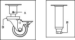
Leg/Caster Installation and Leveling
This appliance must be installed with legs or casters; it cannot be curb mounted. Curb mounting will seriously inhibit this appliances ability to effect proper combustion.
WARNING
This appliance must be installed with the legs or casters provided by the manufacturer.
WARNING
Do not install legs or casters, or perform leveling procedure when unit is in operation or full of cooking medium. Serious injury could result.
Required tools: 7/16 “ wrench and socket and a large pair of water pump pliers. The legs/casters must be installed before connecting the appliance to the gas supply. The legs provide the necessary height to meet sanitation requirements and assure adequate air supply to the combustion system. Use the following procedure.
a.Lay the appliance on its back, being careful not to damage the flue area by pulling on it. Protect the outside of the appliance with cardboard or a drop cloth when laying it down.
b.Attach each leg/caster with the hex head screws and nuts supplied. Each leg/caster requires four ¼-20 x 5/8” hex head screws and nuts. Insure that all screws are tight.
c.Mount the screws from the inside of the appliance with the nut on the outside (bottom) of the appliance. The nuts have lock washers attached to them, therefore it is not necessary to use lock washers
d.When all four legs/casters are securely mounted, stand the unit up, being careful not to put too much weight on any one leg. Adjust the height and level the appliance by adjusting the leveling devices (B) with water pump pliers. On casters, loosen 2 screws (A) before leveling, then retighten.
1
INSTALLATION/OPERATION
Heat Deflector Installation
If the appliance requires a heat deflector, you will find a removable label at the rear top edge of the unit. This label has instructions for positioning and installation of the heat deflector. Refer to the label and the instructions below to install the deflector.
a.Remove the two self-drilling screws from the top, back area of the appliance.
b.Position the heat deflector so that the angled portion of the deflector is facing toward the front of appliance. Secure the heat deflector to the back of the unit using the two previously removed fasteners.
c.When properly installed the angled section of the heat deflector will extend over the flue opening to redirect the heat. It SHOULD NOT cover the flue opening. Never allow anything to block the flue opening; this will cause the appliance to over heat and inhibit proper combustion, which could produce dangerous gases
Installation
If you have completed the above steps that are applicable to the appliance you purchased, the appliance is now ready to be installed. Although it may be possible for you to install and set up your new appliance, it is STRONGLY recommended that you have this done by qualified professionals. A qualified professional will ensure that the installation is safe and meets local building and fire codes.
WARNING
DO NOT obstruct the flow of combustion, ventilation or air openings around the appliance. Adequate clearance around the appliance is necessary for servicing and proper burner operation. Ensure that you meet the minimum clearance requirements specified in this manual.
Installation Clearances
The clearances shown below are for combustible and non-combustible installations and will allow for safe and proper operation of your appliance.
|
Combustible |
Non- |
|
Combustible |
|
|
Construction |
|
|
Construction |
|
|
|
|
|
|
|
Back |
6 in. (15 cm) |
0 |
Sides |
6 in. (15 cm) |
0 |
Floor |
6 in. (15 cm) |
6 in. (15 cm) |
In addition to the above clearances there must also be at least 28 in (71.2cm) of aisle space in front of the unit.
Gas Connection
Your appliance will give you peak performance when the gas supply line is of sufficient size to provide the correct gas flow. The gas line must be installed to meet the local building codes or National Fuel Gas Code ANS Z223.1 and NFPA 54 (latest editions). In Canada, install the appliance in accordance with CSA B149.1 or .2 and local codes. Gas line sizing requirements can be determined by a qualified installation professional, your local gas company or by referring to the National Gas Fuel Code, Appendix C, Table C-4 (for natural gas) and Table C-16 (for propane). The gas line needs to be large enough to supply the necessary amount of fuel to all appliances without losing pressure to any appliance. A properly sized and installed gas line will deliver a minimum supply pressure of 7.0 ± 2.0 inches w.c. (17.4 ± 5 mbar) for natural gas and 12.0 ± 2.0 inches w.c. (29.9 ± 5 mbar) for propane gas to all appliances connected to the supply line, operating simultaneously at full demand. Each appliance is equipped to operate on one certain fuel type. The type of fuel with which the appliance is intended to operate is stamped on the data plate.
2
INSTALLATION/OPERATION
WARNING
NEVER supply the appliance with a gas other than the one that is indicated on the data plate. Using the incorrect gas type will cause improper operation and could result in serious injury or death. If you need to convert the appliance to another type of fuel, contact the dealer you purchased it from.
NOTICE
NEVER use an adaptor to make a smaller gas supply line fit the appliance connection. This may not allow proper gas flow for optimum burner operation, resulting in poor performance and improper operation.
Quick Disconnect Gas Connection
Gas appliances equipped with casters must be installed with connectors that comply with the Standard for Movable Gas Appliances, ANSI Z21.69 • CSA 6.16 latest edition. This connection should include a quick disconnect device that complies with the Standard for Quick Disconnect Devices for Use With Gas Fuel, ANSI Z21.41 • CSA 6.9 latest edition. When installing a quick disconnect you must also install adequate means for limiting the movement of the appliance without depending on the connector and quick-disconnect device or its associated piping to limit the movement of the appliance. The restraining device should be attached to the appliance on the back panel.
Fuel Supply Line Leak and Pressure Testing
The fuel supply system must be tested before the appliance is used. If the fuel line is going to be tested at a pressure greater than ½ PISG (3.45 kPa), insure that that appliance is disconnected from the fuel line. If the fuel line is to be tested at a pressure equal to or less than ½ PSIG (3.45 kPa), the appliance can be connected during the test, but the unit’s gas valve must be shut. Test all gas line connections for leaks with a solution of soap and water when pressure is applied.
Ventilation and Fire Safety Systems
Your new appliance must have proper ventilation to function safely and properly. Exhaust gas temperatures can reach as high as 1100 °F (593 °C). Therefore, it is very important to install a fire safety system. Your ventilation system should be designed to allow for easy cleaning. Frequent cleaning and proper maintenance of the ventilation system and the appliance will reduce the chances of fire. The following tables contain a list of reference documents that will provide guidance on ventilation and fire safety systems. It is not necessarily complete. Additional information can be obtained from CSA International, 8501 East Pleasant Valley Road, Cleveland, OH, 44131 or visit their website at www.csa-international.org.
Hoods and Ventilation Systems
TOPIC |
UL Document |
National Fuel Gas |
|
Code Document |
|||
|
|
||
Exhaust Hoods |
ANSI/UL 70 |
ANSI/NFPA 96 |
|
Power Ventilators |
ANSI/UL 705 |
ANSI/NFPA 96 |
|
Filter Units |
ANSI/UL 900 |
ANSI/NFPA 96 |
Types of Fire Extinguishers and Detection Equipment
Topic |
UL Document |
National Fuel Gas |
|
Code Document |
|||
|
|
||
CO2 Type Extinguishers |
ANSI/UL 154 |
ANSI/NFPA 12 |
|
Dry Chemical Type Extinguishers |
ANSI/UL 299 |
ANSI/NFPA 17 |
|
Water Type Extinguishers |
ANSI/UL 626 |
ANSI/NFPA 13 |
|
Foam Type Extinguishers |
ANSI/UL 8 |
ANSI/NFPA 11 |
|
Sprinklers |
ANSI/UL 199 |
ANSI/NFPA 13 |
|
Smoke Detectors |
ANSI/UL 268 |
ANSI/NFPA 72 |
|
Fire Detection Thermostats |
ANSI/UL 521 |
ANSI/NFPA 72 |
3
 Loading...