


DVD RECEIVER
XV-HTD510
SPEAKER SYSTEM
S-HTD510
Operating Instructions
WARNING: TO PREVENT FIRE OR SHOCK HAZARD, DO NOT EXPOSE THIS APPLIANCE TO RAIN OR MOISTURE.
IMPORTANT
CAUTION
The lightning flash with arrowhead symbol, within an equilateral triangle, is intended to alert the user to the presence of uninsulated "dangerous voltage" within the product's enclosure that may be of sufficient magnitude to constitute a risk of electric shock to persons.
RISK OF ELECTRIC SHOCK
DO NOT OPEN
CAUTION:
TO PREVENT THE RISK OF ELECTRIC SHOCK, DO NOT REMOVE COVER (OR BACK). NO USERSERVICEABLE PARTS INSIDE. REFER SERVICING TO QUALIFIED SERVICE PERSONNEL.
The exclamation point within an equilateral triangle is intended to alert the user to the presence of important operating and maintenance (servicing) instructions in the literature accompanying the appliance.
[FOR U.S. MODEL] CAUTION
•Use of controls or adjustments or performance of procedures other than those specified herein may result in hazardous radiation exposure.
•The use of optical instruments with this product will increase eye hazard.
Information to User
Alteration or modifications carried out without appropriate authorization may invalidate the user’s right to operate the equipment.
Note: This equipment has been tested and found to comply with the limits for a Class B digital device, pursuant to Part 15 of the FCC Rules. These limits are designed to provide reasonable protection against harmful interference in a residential installation. This equipment generates, uses, and can radiate radio frequency energy and, if not installed and used in accordance with the instructions, may cause harmful interference to radio communications. However, there is no guarantee that interference will not occur in a particular installation. If this equipment does cause harmful interference to radio or television reception, which can be determined by turning the equipment off and on, the user is encouraged to try to correct the interference by one or more of the following measures:
–Reorient or relocate the receiving antenna.
–Increase the separation between the equipment and receiver.
–Connect the equipment into an outlet on a circuit different from that to which the receiver is connected.
–Consult the dealer or an experienced radio/TV technician for help.
IMPORTANT NOTICE
[For U.S. model]
The serial number for this equipment is located on the rear panel. Please write this serial number on your enclosed warranty card and keep it in a secure area. This is for your security.
THE STANDBY/ON BUTTON IS SECONDARY CONNECTED AND THEREFORE DOES NOT SEPARATE THE UNIT FROM MAINS POWER IN STANDBY POSITION.
[For Canadian model]
CAUTION: TO PREVENT ELECTRIC SHOCK DO NOT USE THIS (POLARIZED) PLUG WITH AN EXTENSION CORD, RECEPTACLE OR OTHER OUTLET UNLESS THE BLADES CAN BE FULLY INSERTED TO PREVENT BLADE EXPOSURE.
ATTENTION: POUR PREVENIR LES CHOCS ELECTRIQUES NE PAS UTILISER CETTE FICHE POLARISEE AVEC UN PROLONGATEUR, UNE PRISE DE COURANT OU UNE AUTRE SORTIE DE COURANT, SAUF SI LES LAMES PEUVENT ETRE INSERESS A FOND SANS EN LAISSER AUCUNE PARTIE A DECOUVERT.
[For Canadian model]
This Class B digital apparatus complies with Canadian ICES-003.
[Pour le modèle Canadien]
Cet appareil numérique de la classe B est conforme à la norme NMB-003 du Canada.
IMPORTANT SAFETY INSTRUCTIONS
READ INSTRUCTIONS — All the safety and operating instructions should be read before the product is operated.
RETAIN INSTRUCTIONS — The safety and operating instructions should be retained for future reference.
HEED WARNINGS — All warnings on the product and in the operating instructions should be adhered to.
FOLLOW INSTRUCTIONS — All operating and use instructions should be followed.
CLEANING — Unplug this product from the wall outlet before cleaning. The product should be cleaned only with a polishing cloth or a soft dry cloth. Never clean with furniture wax, benzine, insecticides or other volatile liquids since they may corrode the cabinet.
ATTACHMENTS — Do not use attachments not recommended by the product manufacturer as they may cause hazards.
WATER AND MOISTURE — Do not use this product near water — for example, near a bathtub, wash bowl, kitchen sink, or laundry tub; in a wet basement; or near a swimming pool; and the like.
ACCESSORIES — Do not place this product on an unstable cart, stand, tripod, bracket, or table. The product may fall, causing serious injury to a child or adult, and serious damage to the product. Use only with a cart, stand, tripod, bracket, or table recommended by the manufacturer, or sold with the product. Any mounting of the product should follow the manufacturer’s instructions, and should use a mounting accessory recommended by the manufacturer.
CART — A product and cart combination should be moved with care. Quick stops, excessive force, and uneven surfaces may cause the product and cart combination to overturn.
VENTILATION — Slots and openings in the cabinet are provided for ventilation and to ensure reliable operation of the product and to protect it from overheating, and these openings must not be blocked or covered. The openings should never be blocked by placing the product on a bed, sofa, rug, or other similar surface. This product should not be placed in a built-in installation such as a bookcase or rack unless proper ventilation is provided or the manufacturer’s instructions have been adhered to.
POWER SOURCES — This product should be operated only from the type of power source indicated on the marking label. If you are not sure of the type of power supply to your home, consult your product dealer or local power company.
LOCATION – The appliance should be installed in a stable location.
NONUSE PERIODS – The power cord of the appliance should be unplugged from the outlet when left unused for a long period of time.
GROUNDING OR POLARIZATION
÷If this product is equipped with a polarized alternating current line plug (a plug having one blade wider than the other), it will fit into the outlet only one way. This is a safety feature. If you are unable to insert the plug fully into the outlet, try reversing the plug. If the plug should still fail to fit, contact your electrician to replace your obsolete outlet. Do not defeat the safety purpose of the polarized plug.
÷If this product is equipped with a three-wire grounding type plug, a plug having a third (grounding) pin, it will only fit into a grounding type power outlet. This is a safety feature. If you are unable to insert the plug into the outlet, contact your electrician to replace your obsolete outlet.
Do not defeat the safety purpose of the grounding type plug.
POWER-CORD PROTECTION — Power-supply cords should be routed so that they are not likely to be walked on or pinched by items placed upon or against them, paying particular attention to cords at plugs, convenience receptacles, and the point where they exit from the product.
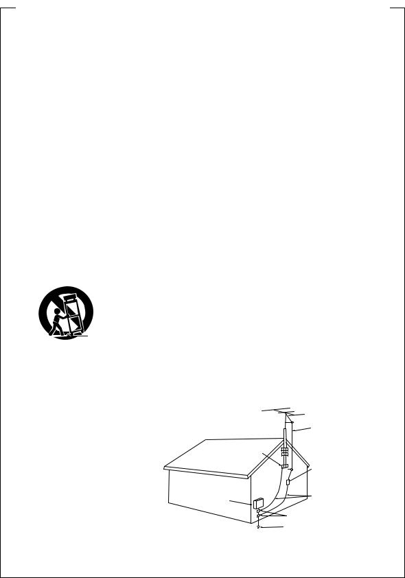
OUTDOOR ANTENNA GROUNDING — If an outside antenna or cable system is connected to the product, be sure the antenna or cable system is grounded so as to provide some protection against voltage surges and built-up static charges. Article 810 of the National Electrical Code, ANSI/NFPA 70, provides information with regard to proper grounding of the mast and supporting structure, grounding of the lead-in wire to an antenna discharge unit, size of grounding conductors, location of antenna-discharge unit, connection to grounding electrodes, and requirements for the grounding electrode. See Figure A.
LIGHTNING — For added protection for this product during a lightning storm, or when it is left unattended and unused for long periods of time, unplug it from the wall outlet and disconnect the antenna or cable system. This will prevent damage to the product due to lightning and power-line surges.
POWER LINES — An outside antenna system should not be located in the vicinity of overhead power lines or other electric light or power circuits, or where it can fall into such power lines or circuits. When installing an outside antenna system, extreme care should be taken to keep from touching such power lines or circuits as contact with them might be fatal.
OVERLOADING — Do not overload wall outlets, extension cords, or integral convenience receptacles as this can result in a risk of fire or electric shock.
GROUND
CLAMP
ELECTRIC
SERVICE
EQUIPMENT
Fig. A
OBJECT AND LIQUID ENTRY — Never push objects of any kind into this product through openings as they may touch dangerous voltage points or short-out parts that could result in a fire or electric shock. Never spill liquid of any kind on the product.
SERVICING — Do not attempt to service this product yourself as opening or removing covers may expose you to dangerous voltage or other hazards. Refer all servicing to qualified service personnel.
DAMAGE REQUIRING SERVICE — Unplug this product from the wall outlet and refer servicing to qualified service personnel under the following conditions:
÷When the power-supply cord or plug is damaged.
÷If liquid has been spilled, or objects have fallen into the product.
÷If the product has been exposed to rain or water.
÷If the product does not operate normally by following the operating instructions. Adjust only those controls that are covered by the operating instructions as an improper adjustment of other controls may result in damage and will often require extensive work by a qualified technician to restore the product to its normal operation.
÷If the product has been dropped or damaged in any way.
÷When the product exhibits a distinct change in
performance — this indicates a need for service.
REPLACEMENT PARTS — When replacement parts are required, be sure the service technician has used replacement parts specified by the manufacturer or have the same characteristics as the original part. Unauthorized substitutions may result in fire, electric shock, or other hazards.
SAFETY CHECK — Upon completion of any service or repairs to this product, ask the service technician to perform safety checks to determine that the product is in proper operating condition.
WALL OR CEILING MOUNTING — The product should not be mounted to a wall or ceiling.
HEAT — The product should be situated away from heat sources such as radiators, heat registers, stoves, or other products (including amplifiers) that produce heat.
ANTENNA
LEAD IN
WIRE
ANTENNA DISCHARGE UNIT (NEC SECTION 810-20)
GROUNDING CONDUCTORS (NEC SECTION 810-21)
GROUND CLAMPS
POWER SERVICE GROUNDING ELECTRODE SYSTEM
(NEC ART 250, PART H)
NEC — NATIONAL ELECTRICAL CODE
Energy-saving design
This system is designed to use 1W of electricity when power is switched to Standby.
This product is for general household purposes. Any failure due to use for other than household purposes (such as longterm use for business purposes in a restaurant or use in a car or ship) and which requires repair will be charged for even during the warranty period.
|
|
|
|
IC |
IN |
D |
|
|
|
|
|
|
|
|
|
|
N |
|
|
|
|
|
|
|
|
||
|
|
|
O |
|
|
S |
|
|
|
|
|
|
|
|
T |
R |
|
|
|
U |
|
|
|
|
|
|
|
|
|
|
|
|
|
|
|
|
|
|
|
||
C |
|
|
|
|
|
|
R |
|
|
|
|
|
|
|
|
|
|
|
|
|
I |
|
|
|
|
||
E |
|
|
|
|
|
|
|
E |
|
|
|
|
|
L |
|
|
|
|
|
|
|
|
|
|
|||
E |
|
|
|
|
|
|
S |
|
|
|
|
||
A |
EST |
1924 |
N |
• |
|
|
|
|
|||||
|
|
S |
|
|
|
|
|
|
|
|
|
||
• |
|
|
|
|
|
|
|
|
|
|
|
||
|
|
|
S |
|
|
IO |
|
|
|
We |
|
|
|
|
|
|
|
O CIAT |
|
|
|
Want You |
|
||||
LISTENING
For A Lifetime
Selecting fine audio equipment such as the unit you’ve just purchased is only the start of your musical enjoyment. Now it’s time to consider how you can maximize the fun and excitement your equipment offers. This manufacturer and the Electronic Industries Association’s Consumer Electronics Group want you to get the most out of your equipment by playing it at a safe level. One that lets the sound come through loud and clear without annoying blaring or distortion-and, most importantly, without affecting your sensitive hearing.
Sound can be deceiving. Over time your hearing “comfort level” adapts to higher volumes of sound. So what sounds “normal” can actually be loud and harmful to your hearing. Guard against this by setting your equipment at a safe level BEFORE your hearing adapts.
To establish a safe level:
÷Start your volume control at a low setting.
÷Slowly increase the sound until you can hear it comfortably and clearly, and without distortion.
Once you have established a comfortable sound level:
÷ Set the dial and leave it there.
Taking a minute to do this now will help to prevent hearing damage or loss in the future. After all, we want you listening for a lifetime.
We WantYou Listening ForALifetime
Used wisely, your new sound equipment will provide a lifetime of fun and enjoyment. Since hearing damage from loud noise is often undetectable until it is too late, this manufacturer and the Electronic Industries Association’s Consumer Electronics Group recommend you avoid prolonged exposure to excessive noise. This list of sound levels is included for your protection.
Decibel
Level Example
30 Quiet library, soft whispers
40 Living room, refrigerator, bedroom away from traffic
50 Light traffic, normal conversation, quiet office
60 Air conditioner at 20 feet, sewing machine
70 Vacuum cleaner, hair dryer, noisy restaurant
80 Average city traffic, garbage disposals, alarm clock at two feet.
THE FOLLOWING NOISES CAN BE DANGEROUS UNDER CONSTANT EXPOSURE
90 Subway, motorcycle, truck traffic, lawn mower
100 Garbage truck, chain saw, pneumatic drill
120 Rock band concert in front of speakers, thunderclap
140 Gunshot blast, jet plane
180 Rocket launching pad
Information courtesy of the Deafness Research Foundation.
|
|
|
|
IC |
IN |
D |
|
|
|
|
|
|
|
|
|
|
|
N |
|
|
|
|
|
|
|
||
|
|
R |
O |
|
|
U |
|
|
|
|
|
|
|
|
T |
|
|
|
|
S |
|
|
|
|
|
|
|
C |
|
|
|
|
T |
|
|
|
|
|
|||
|
|
|
|
|
|
R |
|
|
|
|
|
||
|
|
|
|
|
|
|
I |
|
|
|
|
|
|
E |
|
|
|
|
|
|
|
E |
|
|
|
|
|
L |
|
|
|
|
|
|
|
|
|
|
|
||
E |
|
|
|
|
|
|
S |
|
|
|
|
|
|
|
|
|
|
|
|
|
|
|
We |
||||
• |
|
EST |
1924 |
|
• |
Want You |
|||||||
A |
|
||||||||||||
|
|
|
|
S O C IAT |
|
|
LISTENING |
||||||
|
|
S |
|
|
ION |
|
|
|
|
|
|
||
For A Lifetime
Contents
1 Before You Start |
|
6 Using Surround Sound |
Features |
6 |
Adjusting the bass and treble |
What’s in the box |
6 |
Using P.Bass |
Using this manual |
6 |
Using sound modes |
Putting the batteries in |
|
Listening to surround-sound |
the remote control |
7 |
sources |
Using the remote control |
7 |
Listening to other sources with |
Hints on installation |
7 |
room effects |
Avoiding problems with |
|
Adjusting the effect level |
condensation |
8 |
Listening at low volume |
Moving the system |
8 |
Direct recording |
Discs compatible with this system |
8 |
|
DVD Video regions |
8 |
7 Playing Discs |
|
|
Introduction |
2 Connecting Up |
|
Finding what you want on a disc |
Connecting the speakers |
9 |
Switching camera angles |
Placing the speakers |
10 |
Switching subtitles |
Wall mounting the rear speaker |
|
Switching audio language |
system |
10 |
Switching audio channel |
Connecting to your TV |
11 |
Making a program list |
Connecting the supplied antennas |
12 |
More programming options |
AM loop antenna |
12 |
Using random play |
FM wire antenna |
12 |
Using repeat play |
Connecting external antennas |
12 |
Looping a section of a disc |
External AM antenna |
12 |
Playing CDs only (CD Mode) |
External FM antenna |
12 |
Bookmarking a place in a disc |
Connecting other components |
13 |
Memorizing disc settings |
Connecting the power |
13 |
Displaying disc information |
3 Controls & Displays |
|
8 Using the Timer |
Remote control |
14 |
Using the wake up timer |
Front panel |
15 |
Activating/deactivating the |
Display |
15 |
wake up timer |
|
|
Checking the timer settings |
4 Setting Up |
Using the sleep timer |
|
|
Language settings |
36 |
|
23 |
OSD language |
36 |
|
Audio Language |
37 |
||
23 |
|||
Subtitle Language |
37 |
||
23 |
|||
Auto Language |
37 |
||
|
|||
23 |
DVD Language |
38 |
|
Subtitle Display |
38 |
||
|
|||
24 |
Subtitle Off |
38 |
|
General settings |
38 |
||
24 |
|||
Setup Menu Mode |
38 |
||
25 |
|||
Parental Lock |
39 |
||
25 |
|||
Changing the parental lock level |
39 |
||
|
|||
|
Changing your password |
39 |
|
|
Screen Saver |
40 |
|
26 |
Background Color |
40 |
|
26 |
|
|
|
26 |
11 Additional Information |
|
|
26 |
|
||
Switching the AM frequency |
|
||
26 |
|
||
interval |
41 |
||
26 |
|||
Setting the display brightness |
41 |
||
27 |
|||
Switching the time format |
41 |
||
28 |
|||
Taking care of your system |
41 |
||
28 |
|||
Disc lens cleaner |
41 |
||
28 |
|||
Taking care of your discs |
41 |
||
29 |
|||
Storing discs |
42 |
||
29 |
|||
Discs to avoid |
42 |
||
29 |
|||
Glossary |
42 |
||
30 |
|||
Language code list |
43 |
||
30 |
|||
Troubleshooting |
45 |
||
|
|||
|
Resetting the system |
45 |
|
31 |
Switching the demo mode on/off |
45 |
|
Screen sizes and disc formats |
46 |
||
31 |
Specifications |
47 |
|
|
|
32
32
Switching on and setting the clock |
16 |
9 Advanced Sound Setup |
|
Setting up for surround sound |
16 |
|
|
|
|
||
Setting the speaker distances |
16 |
Advanced sound settings |
33 |
Balancing the surround sound |
17 |
LFE attenuator |
33 |
Using the Setup Navigator |
18 |
Dynamic Range Control |
33 |
|
|
Dual-mono setting |
34 |
5 Getting Started |
|
Adjusting channel volume levels |
34 |
|
|
|
|
Playing DVDs, CDs and Video CDs |
19 |
10 DVD Setup Menu |
|
Basic playback controls |
19 |
|
|
|
|
||
Navigating DVD disc menus |
20 |
Using the DVD Setup menu |
35 |
Navigating Video CD PBC menus 20 |
Video settings |
35 |
|
Exchanging discs |
21 |
TV Screen |
35 |
Listening to the radio |
21 |
Picture Quality |
35 |
Improving FM stereo sound |
22 |
S-Video Out |
36 |
Saving station presets |
22 |
Still Picture |
36 |
Listening to station presets |
22 |
On Screen Display |
36 |
Listening to other components |
22 |
Angle Indicator |
36 |

1 Before You Start
Features
•Superlative audio performance with Dolby Digital* and DTS** software
The XV–HTD510 delivers breathtaking sound quality with Dolby Digital and DTS discs.
•Graphical Setup Navigator
Setting up your home theater is easy using the graphical Setup Navigator. Answer the questions that appear on-screen and the Setup Navigator makes the necessary video and language settings for you.
• This product incorporates copyright protection technology that is protected by method claims of certain U. S. patents and other intellectual property rights owned by Macrovision Corporation and other rights owners. Use of this copyright protection technology must be authorized by Macrovision Corporation, and is intended for home and other limited viewing uses only unless otherwise authorized by Macrovision Corporation. Reverse engineering or disassembly is prohibited.
*Manufactured under license from Dolby Laboratories. “Dolby” and the double-D symbol are trademarks of Dolby Laboratories. Confidential unpublished works. © 1992-1997 Dolby Laboratories. All rights reserved.
**“DTS” and “DTS Digital Surround” are registered trademarks of Digital Theater Systems, Inc.
What’s in the box
Confirm that the following accessories are in the box when you open it.
•Remote control
•AA/R6P dry cell batteries x2
•AM loop antenna
•FM antenna
•Video cord (yellow)
•Power cord
•These operating instructions
•Warranty card
•Speaker cords 5m (16 ft. 5 in.) x2 (for front L-R speakers)
•Speaker cord 2m (6 ft. 7 in.) x1 (for center speaker)
•Speaker cords 6m (19 ft. 8 in.) x2 (for rear L-R speakers)
•Speaker cord 3m (9 ft. 10 in.) x1 (for subwoofer)
Using this manual
This manual is for the XV–HTD510 DVD Receiver. It is divided into several sections: system basics and connecting up (chapters 1 and 2); an explanation of the controls and displays (chapter 3); setting up for surround sound and other preferences (chapter 4); getting started (chapter 5); advanced features (chapters 6–9); system settings and preferences (chapter 10). Chapter 11 provides additional information, including a glossary of terms used in this manual, and a troubleshooting section.
6
En
Before You Start |
1 |
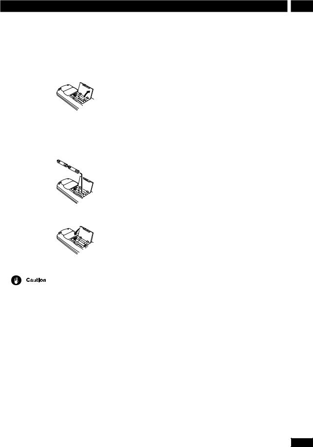
Putting the batteries in the remote control
1Open the battery compartment cover on the back of the remote control.
2Insert two AA/R6P batteries into the battery compartment following the indications (ª, ·) inside the compartment.
3 Close the cover.
•Remove the batteries if the remote is not going to be used for a month or more.
•Remove dead batteries promptly—they can leak and damage the unit.
•When disposing of used batteries, please comply with governmental regulations or environmental public institution’s rules that apply in your country or area.
Using the remote control
Keep in mind the following when using the remote control:
•Make sure that there are no obstacles between the remote control and the remote sensor on the unit.
•Use within 7 meters (21 feet) of the remote sensor and at an angle of less than 30º.
•Remote operation may become unreliable if strong sunlight or fluorescent light is shining on the unit’s remote sensor.
•Remote controllers for different devices can interfere with each other. Avoid using remotes for other equipment located nearby this unit.
•Replace the batteries when you notice the operating range of the remote starts to decrease.
Hints on installation
We want you to enjoy using this unit for years to come, so please bear in mind the following points when choosing a suitable location for it:
Do...
Use in a well-ventilated room.
Place on a solid, flat, level surface, such as a table, shelf or stereo rack.
Don’t...
Use in a place exposed to high temperatures or humidity, including near radiators and other heatgenerating appliances.
Place on a window sill or other place where the system will be exposed to direct sunlight.
Use in an excessively dusty or damp environment.
Place directly on top of an amplifier, or other component in your stereo system that becomes hot in use.
7
En
1Before You Start
Use near a television or monitor as you may experience interference—especially if the television uses an indoor antenna.
Use in a kitchen or other room where the system may be exposed to smoke or steam.
Use on a thick rug or carpet, or cover with cloth— this may prevent proper cooling of the unit.
Place on an unstable surface, or one that is not large enough to support all four of the unit’s feet.
Avoiding problems with condensation
Condensation may form inside the system if it is brought into a warm room from outside, or if the temperature of the room rises quickly. Although the condensation won’t damage the system, it may temporarily impair its performance. For this reason you should leave it to adjust to the warmer temperature for about an hour before switching on and using.
Moving the system
If you need to move the system, first switch it off and unplug from the wall outlet. Never lift or move the unit during playback—discs rotate at a high speed and may be damaged.
Discs compatible with this system
Any disc that displays one of the following logos should play in this system. Other formats, including DVD-RAM, DVD-ROM, DVD-Audio, CD-ROM, SACD and Photo CD will not play.
DVD Video compatibility:
•Single-sided or double-sided discs
•Single layer or dual layer discs
•Dolby Digital, DTS, MPEG or Linear PCM digital audio
•MPEG-2 digital video
DVD discs are generally divided into one or more titles. Titles may be further subdivided into chapters.
8
Audio CD compatibility:
•12cm or 8cm (5” or 3”) discs
•Linear PCM digital audio
•CD-Audio, CD-R* and CD-RW* formats CDs are divided into tracks.
* This system can play CD-R and CD-RW discs recorded with audio. However, depending on the condition of the player and the disc, you may find that not all discs will play successfully. (For example, if the disc is scratched or dirty, or if the player’s pickup lens is dirty.) Note that this unit cannot record onto recordable discs.
Video CD compatibility:
•12cm or 8cm (5” or 3”) discs
•MPEG-1 digital audio
•MPEG-1 digital video
Video CDs are divided into tracks.
DVD Video regions
1 ALL
All DVD Video discs carry a region mark on the case somewhere that indicates which region(s) of the world the disc is compatible with. Your DVD system also has a region mark, which you can find on the rear panel. Discs from incompatible regions will not play in this system. Discs marked ALL will play in any player.
En

Connecting Up |
2 |
Before making or changing any rear panel connections, make sure that all the components are switched off and unplugged from the power supply.
Center
Connecting the speakers
Subwoofer
FRONT |
REAR |
L |
L |
L |
R |
R |
R |
|
SPEAKERS |
|
|
|
H |
|
|
1 |
|
|
H |
SUB-
WOOFER SPEAKERS CENTER
Front R
AC INLET
Front L
Rear R
The speaker terminal tabs and supplied speaker cables are color-coded for simpler connection.
1Use the speaker cables with the red sleeves to connect the front speakers to the FRONT L and FRONT R terminals.
2Use the speaker cables with the blue sleeves to connect the rear speakers to the REAR L and REAR R terminals.
3Use the speaker cable with the grey sleeves to connect the subwoofer to the SUBWOOFER terminals.
4Use the speaker cable with the green sleeves to connect the center speaker to the CENTER terminals.
For proper sound, it’s important to connect the positive (colored) and negative (black) terminals for each speaker correctly.
Rear L
1 Twist off the protective covers on the ends of the speaker
cable.
2Press the speaker terminal tabs to open and insert the wire with the colored sleeve into the colored terminal and the other wire into the black terminal.
3Release the speaker terminal tabs to secure the
speaker cable.
Colored sleeve
Black tab
4Connect the other end of the cable to the speaker in the same way.
Colored sleeve
Black tab
Colored tab
9
En
2 Connecting Up
Do not connect any of the supplied speakers to any other amplifier. This may result in malfunction or fire.
This DVD receiver has been designed for best performance when connected to the supplied speakers. We do not, therefore, recommend that you connect and use other speakers with this system.
Placing the speakers
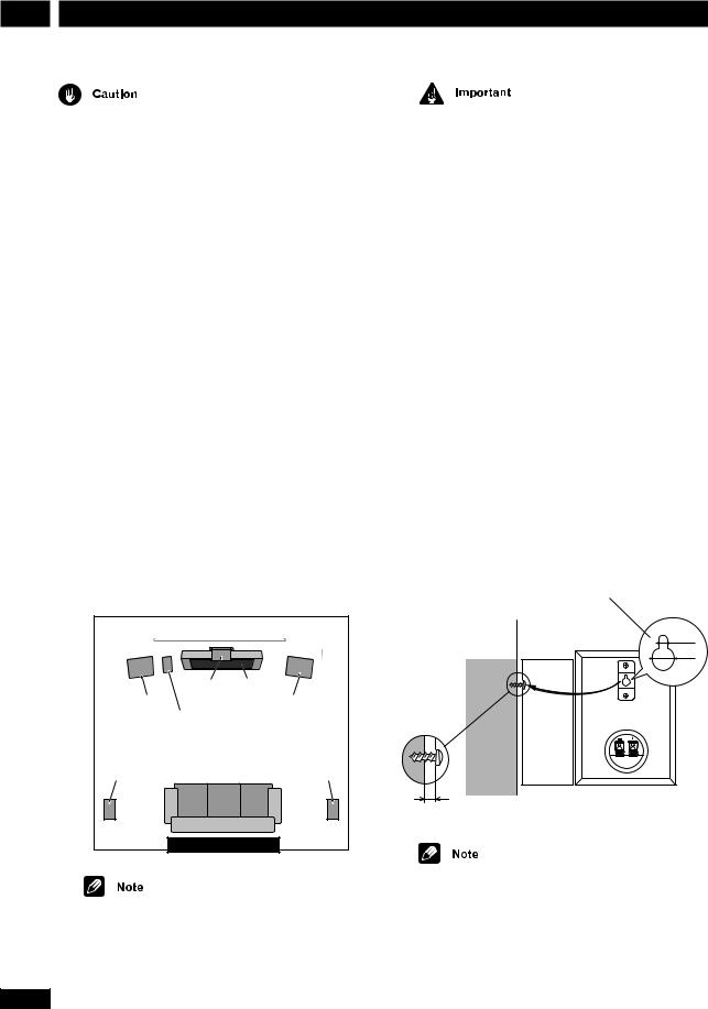
Where you put your speakers in the room has a big effect on the quality of the sound. The following guidelines should help you to get the best sound from your system.
•The subwoofer can be placed on the floor. Ideally, the other speakers should be at about ear-level when you’re listening to them. Putting the speakers on the floor (except the subwoofer), or mounting them very high on a wall is not recommended.
•For the best stereo effect, place the front speakers 2– 3m (6–9ft.) apart.
•The rear speakers should not be further away from your listening position than the front speakers.
•The center speaker should be as close as possible to the TV screen so that movie dialog is localized properly.
2-3m (6-9ft.) |
|
Center |
TV |
Front L |
Front R |
Subwoofer |
|
Rear L |
Rear R |
Your listening position |
|
If you install the center speaker on top of your TV, be sure to secure it with tape or by some other suitable means. An unsecured speaker may fall from the TV due to external shocks such as earthquakes, endangering
those nearby or damaging the speaker.
10
The front and center speakers supplied with this system are magnetically shielded. However, placing them extremely close to a television may result in color distortion on the screen. If this happens, move the speakers a little further away and switch off the television for 15–30 minutes.
The rear speakers and subwoofer are not magnetically shielded, so they should not be placed near a TV or monitor.
Wall mounting the rear speaker system
Before mounting
• Remember that this speaker system is heavy and that its weight may cause the wood screw to work loose or the wall to fail to support it, in which case the speaker system may fall on the floor. This is extremely dangerous. Make absolutely sure that the wall is sturdy enough to support the weight of the speaker system. Do not mount it on plywood boards or soft-surface walls.
The mounting screws are not included with this unit. Please find the correct screws for your application.
Wall-mounting bracket
3.5 mm  9.5 mm
Wood screw
Protrude:5-7mm
•If you are unsure of the qualities and strength of the walls, consult a professional for advice.
•PIONEER is not responsible for any accidents or damage that result from improper installation.
En
Connecting Up
Connecting to your TV
FRONT |
REAR |
L |
L |
COAX |
|
R |
R |
DIGITALR |
|
|
|
|
IN |
TV/ |
|
AC INLET |
|
|
VCR |
IN |
VOLTAGE |
SUB- |
CENTER |
|
SELECTOR |
|
WOOFER |
|
|
|
SPEAKERS |
|
|
|
|
|
240V |
|
|
DIGITAL COAX |
|
|
R L |
|
|
220- |
|
|
IN |
TV/ |
IN |
|
IN |
ANTENNA |
230V |
Supplied video cord |
|
OUT OUT |
AUX |
|
|
||||
|
VIDEO |
VCR |
IN |
|
|
H |
110- |
|
|
|
|
|
|
AM |
127V |
|
|
|
VIDEO |
|
|
|
|
LOOP |
|
|
1 |
1 |
|
|
|
|
FM |
|
|
S-VIDEO |
|
|
|
|
UNBAL |
|
|
|
|
OUT |
|
OUT |
AUX |
|
75Ω |
|
|
|
|
|
|
|
H |
|
|
|
|
S-VIDEO |
|
|
|
OUT |
|
|
|
|
OUT |
|
|
|
|
|
|
VIDEO
IN
S-VIDEO
IN
S-Video cord (not supplied)
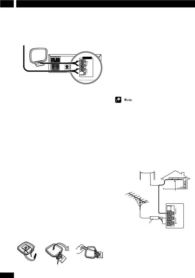
1Use the supplied yellow video cord to connect the VIDEO OUT jack to a video input on your TV.
Alternatively, you can use an S-Video cable (not supplied) to connect the S-VIDEO OUT jack to an S- Video input on your TV. S-Video should give you better picture quality than using the standard VIDEO OUT.
• See S-Video Out on page 36 for how to change the S-Video setting between S1 and S2 format.
2Optionally: Use a stereo audio cord to connect the audio outs of your TV (or VCR) to the TV/VCR IN jacks.
This will enable you to hear the TV (or VCR) sound through this system.
• If you want to connect both your TV and VCR, use the TV/VCR IN jacks for one and the AUX IN jacks for the other.
Placing the main unit too close to your TV may cause interference, especially if you’re using an indoor antenna. If you notice interference, move the unit away from the TV.
2
11
En
2 Connecting Up
Connecting the supplied antennas
FM wire
antenna AM loop antenna
It’s also possible to fix the AM antenna to a wall. When installing on a wall or other surface, perform steps 4 and 5 after first securing the stand with screws. Before fixing, make sure that the reception is satisfactory.
|
ANTENNA |
|
|
|
|
H |
AC INLET |
|
|
SELECTORVOLTAGE |
|
SPEAKERS |
|
AM |
240V |
|
ANTENNA LOOP |
220- |
|
|
230V |
||
|
H |
ANTENNA |
110- |
|
|
127V |
|
Ω FM
H UNBAL
75Ω


 H
H
The supplied antennas provide a simple way to listen to AM and FM radio. If you find that reception quality is poor, an outdoor antenna should give you better sound quality—see Connecting external antennas below for more on how to do this.
FM wire antenna
•Connect the FM wire antenna to the FM UNBAL 75Ω terminals in the same way as
the AM loop antenna.
For best results, extend the FM antenna fully and fix to a wall or door frame. Don’t drape loosely or leave coiled up.
The signal earth (H) is designed to reduce noise that occurs when an antenna is connected. It is not an electrical safety earth.
AM loop antenna
1Pull off the protective shields of both AM antenna wires.
2Press the antenna terminal tabs to open and insert one wire into each terminal.
3Release the tabs to secure the AM antenna wires.
4Bend the stand in the direction indicated by the arrow.
5 Clip the loop onto the stand.
6Place the AM antenna on a flat surface and point in the direction giving the best reception.
Avoid placing near computers, television sets or other electrical appliances and do not let it come into contact with metal objects.
4 |
5 |
5 |
12
Connecting external antennas
External AM antenna
Use 5–6 meters (15–18 ft.) of vinyl-insulated wire and set up either indoors or outdoors. Leave the supplied AM loop antenna connected.
Outdoor
AM antenna
Indoor
AM antenna


 H
H
AM
LOOP
ANTENNA
FM
UNBAL 75Ω
H
75 Ω coaxial cable
External FM antenna
Use 75Ω coaxial cable to hook up an external FM antenna. Do not leave the supplied FM wire antenna attached.
En
Connecting Up |
2 |
Connecting other components
FRONT |
|
REAR |
|
|
|
|
|
|
|
OAX |
|
|
R |
|
L |
|
|
L |
L |
L |
TV/ |
|
|
|
||
R |
R |
R |
|
|
|
|
|
|
|
|
|
VCR |
|
|
|
|
AC INLET |
|
|
|
|
IN |
|
|
|
VOLTAGE |
|
|
|
|
|
|
|
SELECTOR |
|
SUB- |
SPEAKERS |
CENTER |
|
|
|
|
|
240V |
WOOFER |
|
|
|
|
|
|||
|
|
|
DIGITAL |
COAX |
R |
L |
|
220- |
|
|
|
IN |
|
|
|
|
230V |
|
|
|
|
|
|
|
H |
110- |
|
|
|
OUT |
IN |
|
|
127V |
|
|
|
|
VIDEO |
|
|
|
|
|
|
|
|
1 |
|
|
|
H |
|
|
|
|
AUX |
|
|
|
|
|
|
|
|
VIDEO |
|
|
|
Ω |
|
|
|
|
S-OUT |
|
OUT |
|
|
|
OUT
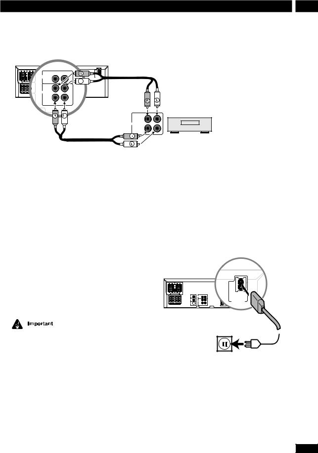
OUT (PLAY)
Analog
IN (REC)
Tape deck, VCR, MD recorder, etc.
1Use a stereo audio cable to connect the AUX IN jacks to the analog outputs of an external component.
This will allow you to play the component through this system.
2Use a stereo audio cable to connect the AUX OUT jacks to the analog inputs of an external component.
This will allow you to record from this system to an external tape/MD/CD recorder.
3Use a digital coaxial cable to connect the DIGITAL IN COAX jack to the digital output of an external component.
This will allow you to play a digital audio component (MD player, etc.) through this system.
The DIGITAL IN COAX jack should only be connected to a PCM audio output (32, 44.1 or 48kHz). These include CD, MD and DAT players and satellite receivers. Check the instructions that came with your other component for more details.
Connecting the power
Before connecting the power and switching on for the first time make sure that everything is connected properly.
1Plug one end of the supplied power cord into the AC INLET.
2Plug the other end into a household power outlet.
SPEAKERS
AC INLET
VOLTAGE
SE ECTOR
13
En
3 Controls & Displays
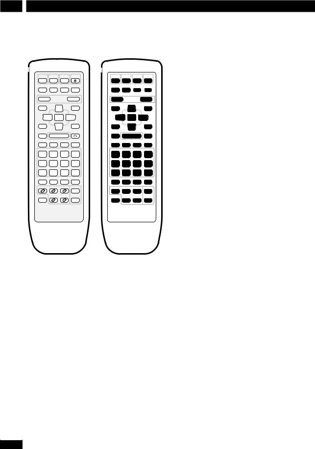
Remote control
DVD |
TUNER |
TV |
STANDBY |
|
|
|
|
/CD |
/BAND |
/AUX |
/ON |
|
|
|
|
|
|
|
|
1 |
2 |
3 |
4 |
MUTE |
TEST TONE SURROUND |
DSP |
|
|
|
|
|
CH LEVEL |
MODE |
|
|
|
|
||
|
|
|
|
5 |
6 |
7 |
8 |
— VOLUME |
+ |
9 |
|
|
10 |
||
DVD SETUP |
|
|
SYSTEM SETUP |
|
|
|
|
|
5 |
|
11 |
|
12 |
13 |
|
|
|
|
|
|
|||
2 ENTER |
3 |
14 |
|
15 |
16 |
||
TOP MENU |
∞ |
|
17 |
|
18 |
19 |
|
MENU |
SOUND |
|
|||||
|
|
|
RETURN |
20 |
|
21 |
22 |
7 |
6 |
|
|
||||
— PREV eSTEP/SLOW E |
NEXT + |
23 |
24 |
25 |
26 |
||
4 |
1 |
¡ |
¢ |
||||
CONDITION |
LAST MEMO |
SEARCH |
DVD DISP |
|
|
|
|
1 |
2 |
3 |
CLEAR |
27 |
28 |
29 |
30 |
ANGLE |
MONO |
SLEEP |
FL DIMMER |
|
|
|
|
4 |
5 |
6 |
>10 |
31 |
32 |
33 |
34 |
PROGRAM |
RANDOM |
REPEAT |
REP A—B |
|
|
|
|
7 |
8 |
9 |
10/0 |
35 |
36 |
37 |
38 |
CD MODE |
AUDIO |
SUBTITLE |
SYSTEM DISP |
|
|
|
|
|
|
|
|
39 |
40 |
41 |
42 |
DISC 1 |
DISC 2 |
DISC 3 |
DISC SKIP |
|
|
|
|
|
|
|
|
43 |
44 |
45 |
46 |
SHIFT |
DISC 4 |
DISC 5 |
OPEN/ |
|
|
|
|
CLOSE |
47 |
48 |
49 |
50 |
|||
|
|
|
0 |
||||
1DVD/CD Pages 19, 31
2 TUNER/BAND Pages 21-22, 31
3 TV/AUX Pages 22, 31
4STANDBY/ON Page 19
5 MUTE Silences/restores all sound.
6 TEST TONE/CH LEVEL Page 17
7 SURROUND MODE Pages 17, 24
8DSP Page 24
9 VOLUME – Lowers the volume.
10VOLUME + Raises the volume.
11DVD SETUP Pages 18, 35
12Cursor up Use for navigating menus and on-screen displays.
13SYSTEM SETUP Pages 16, 22, 31-34, 41
14Cursor left Use for navigating menus and on-screen displays.
14
15ENTER
16Cursor right Use for navigating menus and on-screen displays.
17MENU Page 20
TOP MENU Page 20
18Cursor down Use for navigating menus and on-screen displays.
19SOUND Page 24
207 Page 19
213/8Page 19
22RETURN  Page 20
234 / –PREV Pages 19-20
241/ STEP/SLOW ePages 19-20
25¡/ STEP/SLOW EPages 19-20
26¢ / NEXT+ Pages 19-20
271 / CONDITION (SHIFT & 1) Page 30
282 / LAST MEMO (SHIFT & 2) Page 29
293 / SEARCH (SHIFT & 3) Page 26
30CLEAR Clears/cancels various functions
DVD DISP (SHIFT & CLEAR) Page 30
314 / ANGLE (SHIFT & 4) Page 26
325 / MONO (SHIFT & 5) Page 22
336 / SLEEP (SHIFT & 6) Page 32
34>10 Selects numbers over 10 Page 20
FL DIMMER (SHIFT & >10) Page 41
357 / PROGRAM (SHIFT & 7) Page 28
368 / RANDOM (SHIFT & 8) Page 28
379 / REPEAT (SHIFT & 9) Page 28
38REP A–B (SHIFT & 10/0) Page 29
10/0 Number button (10 and 0)
39CD MODE Page 29
40AUDIO Page 26
41SUBTITLE Page 26
42SYSTEM DISP Page 16
43DISC 1 Page 20
44DISC 2 Page 20
45DISC 3 Page 20
46DISC SKIP Pages 19, 21
47SHIFT Hold down to access secondary button functions
48DISC 4 Page 20
49DISC 5 Page 20
50OPEN/CLOSE 0Pages 19, 21
En

Controls & Displays |
3 |
Front panel
|
|
1 |
|
2 |
|
|
|
|
|
3 |
|
|
4 |
5 |
|
6 |
|
|
|
|
|
|
|
|
|
|
|
|
|
DISC SKIP EXCHANGE |
0 OPEN/CLOSE |
||
|
|
|
|
|
|
|
1 |
2 |
3 |
|
4 |
5 |
|
|
|
|
|
|
|
|
|
|
VIDEO |
|
|
|
|
|
|
|
|
|
|
|
|
|
|
|
|
|
|
|
|
|
|
|
|
|
|
VOLUME |
DVD RECEIVER XV-HTD510 |
|
|
|
|
|
|
|
|
|
|
|
|
|
|
||
STANDBY/ON |
|
|
|
|
|
|
|
|
|
|
|
|
|
|
|
|
STANDBY |
CD |
ADVANCED |
DSP |
|
|
|
|
DISC |
1 |
2 |
3 |
4 |
5 |
|
|
|
|
MODE |
THEATER |
|
|
|
|
|
|
|
|
|
|
|
|
|
|
1 |
|
|
|
|
|
|
|
|
|
|
|
|
|
|
|
|
|
DVD/CD |
TUNER/BAND |
TV/AUX |
CD MODE |
7 |
3/8 |
4.1 |
|
¡.¢ |
|
|
|
|
|
||
|
|
|
|
|
|
|
|
|
|
|
|
|
|
|
|
PHONES |
18 |
17 |
16 |
15 |
14 |
13 |
12 |
11 |
|
10 |
|
9 |
|
8 |
7 |
||
1 |
STANDBY indicator |
9 |
DISC indicators |
|
CD MODE indicator |
10 |
¡• ¢ Pages 19-20 |
|
ADVANCED THEATER indicator |
11 |
4 • 1 Pages 19-20 |
|
DSP indicator |
12 |
6 Page 19 |
2 |
Disc tray |
13 |
7 Page 19 |
3 |
Disc buttons Page 20 |
14 |
CD MODE Page 29 |
4 |
DISC SKIP Pages 19, 21 |
15 |
TV/AUX (/DIGITAL IN) Pages 22, 31 |
5 |
EXCHANGE Page 21 |
16 |
TUNER/BAND Pages 21-22 |
6 |
0OPEN/CLOSE Pages 19, 21 |
17 |
DVD/CD Pages 19, 31 |
7 |
PHONES Plug in a pair of headphones here. |
18 |
STANDBY/ON Page 19 |
8VOLUME Turn to adjust the volume.
Display
1 |
|
2 |
|
3 |
|
4 |
|
5 |
|
6 |
|
7 |
|
8 |
|
9 |
|
10 |
|
11 |
|
12 |
2DIGITAL |
2PRO LOGIC |
MIDNIGHT |
CONDITION |
ANGLE |
LAST MEMO |
||
|
|
|
|
|
L |
C |
R |
ALL DISCS |
|
|
|
|
|
LFE |
|
|
|
|
|
|
|
|
|
RANDOM |
|
|
|
|
Ls |
S |
Rs |
REPEAT |
|
|
|
|
|||
|
|
|
|
|
|
|
|
|
|
17 |
|
16 |
|
15 |
|
14 |
|
|
13 |
|
1 |
DTS page 42 |
|
|
|
|
11 |
ANGLE page 26 |
|||||
2 |
2DIGITAL pages 23, 42 |
12 |
LAST MEMO page 29 |
|||||||||
3 |
2PRO LOGIC page 23 |
13 |
Channel indicators Show which channels are available |
|||||||||
4 |
Timer indicator page 31 |
|
|
on the current disc. |
||||||||
5 |
Sleep indicator page 32 |
14 |
Character display When playing discs : Left to right |
|||||||||
6 |
Tuned indicator page 21–22 |
|
|
displays disc number, title, chapter/track, minutes, seconds. |
||||||||
7 |
FM stereo indicator page 22 |
15 |
RANDOM page 28 |
|||||||||
8 |
FM mono indicator page 22 |
16 |
REPEAT page 28 |
|||||||||
9 |
MIDNIGHT page 25 |
17 |
DISC | ALL DISCS Indicates the random or repeat |
|||||||||
10 CONDITION page 30 |
|
|
mode ; page 28–29 |
|||||||||
15
En
 Loading...