


XV-EV1000
Pioneer XV-EV1000, S-EV700V, XV-EV700, S-EV1000V, XV-EV500 User Manual
...
Stereo Cassette Deck Receiver
XV-EV500
XV-EV700
XV-EV1000
Speaker System
S-EV500V
S-EV700V
S-EV1000V
Operating Instructions
IMPORTANT
The lightning flash with arrowhead symbol,
within an equilateral triangle, is intended to
alert the user to the presence of uninsulated
"dangerous voltage" within the product's
enclosure that may be of sufficient
magnitude to constitute a risk of electric
shock to persons.
CAUTION
RISK OF ELECTRIC SHOCK
DO NOT OPEN
CAUTION:
TO PREVENT THE RISK OF ELECTRIC
SHOCK, DO NOT REMOVE COVER (OR
BACK). NO USER-SERVICEABLE PARTS
INSIDE. REFER SERVICING TO QUALIFIED
SERVICE PERSONNEL.
The exclamation point within an equilateral
triangle is intended to alert the user to the
presence of important operating and
maintenance (servicing) instructions in the
literature accompanying the appliance.
D3-4-2-1-1_En-A
CAUTION
This product is a class 1 laser product, but this
product contains a laser diode higher than Class 1.
To ensure continued safety, do not remove any covers
or attempt to gain access to the inside of the product.
Refer all servicing to qualified personnel.
The following caution label appears on your unit.
Location: bonnet of the unit
Taiwan model
WARNING
This equipment is not waterproof. To prevent a fire
or shock hazard, do not place any container filed
with liquid near this equipment (such as a vase or
flower pot) or expose it to dripping, splashing, rain
or moisture.
WARNING
Before plugging in for the first time, read the following
D3-4-2-1-3_A_En
section carefully.
The voltage of the available power supply differs
according to country or region. Be sure that the
power supply voltage of the area where this unit
will be used meets the required voltage (e.g., 230V
or 120V) written on the rear panel.
D3-4-2-1-4_A_En
WARNING
To prevent a fire hazard, do not place any naked
flame sources (such as a lighted candle) on the
equipment.
D3-4-2-1-7a_A_En
Operating Environment
Operating environment temperature and humidity:
+5 ºC – +35 ºC (+41 ºF – +95 ºF); less than 85 %RH
(cooling vents not blocked)
Do not install this unit in a poorly ventilated area, or in
locations exposed to high humidity or direct sunlight (or
strong artificial light)
D3-4-2-1-7c_A_En
All other models
Location: rear of the unit
CLASS 1
LASER PRODUCT
D3-4-2-1-8_A_En
This product complies with the Low Voltage Directive
(73/23/EEC, amended by 93/68/EEC), EMC Directives
(89/336/EEC, amended by 92/31/EEC and
93/68/EEC).
Recording equipment and copyright: Recording
equipment should be used only for lawful copying
and you are advised to check carefully what is lawful
copying in the country in which you are making a
copy. Copying of copyright material such as films or
music is unlawful unless permitted by a legal
exception or consented to by the rightowners.
VENTILATION CAUTION
When installing this unit, make sure to leave space
around the unit for ventilation to improve heat
radiation (at least 30 cm at top, 15 cm at rear, and
15 cm at each side).
WARNING
Slots and openings in the cabinet are provided for
ventilation to ensure reliable operation of the
product, and to protect it from overheating. To
prevent fire hazard, the openings should never be
blocked or covered with items (such as newspapers,
table-cloths, curtains) or by operating the
equipment on thick carpet or a bed.
D3-4-2-1-9a_En
K018_En
D3-4-2-1-7b_A_En
Y
T
CAUTION : USE OF CONTROLS OR ADJUSTMENTS OR PERFORMANCE OF PROCEDURES OTHER THAN THOSE
T
SPECIFIED HEREIN MAY RESULT IN HAZARDOUS RADIATION EXPOSURE.
CAUTION : THE USE OF OPTICAL INSTRUMENTS WITH THIS PRODUCT WILL INCREASE EYE HAZARD.
D6-8-2-1_En
NOTE: This equipment has been tested and found to comply with the limits for a Class B digital device, pursuant to
Part 15 of the FCC Rules. These limits are designed to provide reasonable protection against harmful interference in
a residential installation. This equipment generates, uses, and can radiate radio frequency energy and, if not
installed and used in accordance with the instructions, may cause harmful interference to radio communications.
However, there is no guarantee that interference will not occur in a particular installation. If this equipment does
cause harmful interference to radio or television reception, which can be determined by turning the equipment off
and on, the user is encouraged to try to correct the interference by one or more of the following measures:
– Reorient or relocate the receiving antenna.
– Increase the separation between the equipment and receiver.
– Connect the equipment into an outlet on a circuit different from that to which the receiver is connected.
– Consult the dealer or an experienced radio/TV technician for help.
D8-10-1-2_En
Information to User
Alteration or modifications carried out without appropriate authorization may invalidate the user’s right to operate
the equipment.
D8-10-2_En
CAUTION: This product satisfies FCC regulations when shielded cables and connectors are used to connect the
unit to other equipment. To prevent electromagnetic interference with electric appliances such as radios and
televisions, use shielded cables and connectors for connections.
D8-10-3a_En
CAUTION
The STANDBY/ON switch on this unit will not
completely shut off all power from the AC outlet.
Since the power cord serves as the main disconnect
device for the unit, you will need to unplug it from
the AC outlet to shut down all power. Therefore,
make sure the unit has been installed so that the
power cord can be easily unplugged from the AC
outlet in case of an accident. To avoid fire hazard,
the power cord should also be unplugged from the
AC outlet when left unused for a long period of time
(for example, when on vacation).
D3-4-2-2-2a_A_En
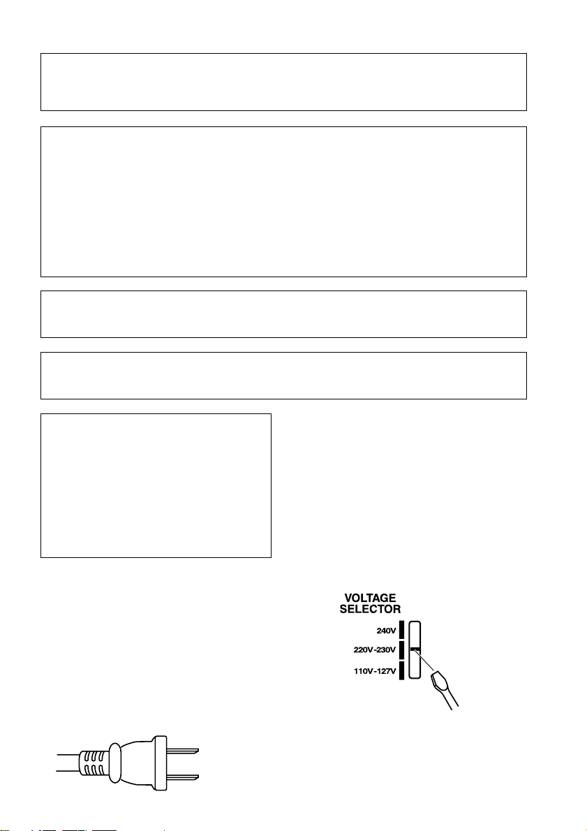
Voltage selector
ou can find the voltage selector switch on the rear
panel of multi-voltage models.
The factory setting for the voltage selector is
220V–230V. Please set it to the correct voltage for
your country or region.
• Saudi Arabia operates on 127V and 220V mains
voltage. Please set to the correct voltage before using.
• For Taiwan, please set to 110V–127V before using.
• For Mexico, please set to 110V–127V before using.
Before changing the voltage, disconnect the AC power
cord. Use a medium size screwdriver to change the
voltage selector switch.
CAUTION
hese speaker terminals carry HAZARDOUS LIVE
voltage. To prevent the risk of electric shock when
connecting or disconnecting the speaker cables,
disconnect the power cord before touching any
uninsulated parts.
D3-4-2-2-3_A_En
For Taiwan exclusively
aiwanese two pin flat-bladed plug
Medium size
screwdriver
D3-4-2-1-5_En

Thank you for buying this Pioneer product.
Please read through these operating instructions so that you will know how to operate your model
properly. After you have finished reading the instructions, put them in a safe place for future
reference
Contents
.
01 Before you start
Checking what’s in the box
Loading the batteries
Range of the remote control unit
Attaching the non-skid pads
Removing the front speaker grilles
. . . . . . . . . . . . . . . 6
. . . . . . . . . . . . . . . . . . . 6
. . . . . . . . . . 6
. . . . . . . . . . . . . . 7
. . . . . . . . 7
02 Connecting up
Connecting the speaker terminals
Multichannel speaker connections
Hints on speaker placement
Attaching the surround speakers to the
speaker stands
Optional surround speaker connections
Connecting the radio antennas
Connecting external antennas
Connecting to your TV
Connecting using the component video
output
Connecting auxiliary components
Connecting the power
. . . . . . . . . . . . . . . . . . . . . . 10
. . . . . . . . . . . . . . . . . . 11
. . . . . . . . . . . . . . . . . . . . . . . . . . . . 12
. . . . . . . . . . . . . . . . . . 13
. . . . . . . . . 8
. . . . . . . . . 9
. . . . . . . . . . . . . 9
. . . . 10
. . . . . . . . . . . 10
. . . . . . . . . . 11
. . . . . . . . . 12
03 Controls and displays
Front panel
Display
Remote control
. . . . . . . . . . . . . . . . . . . . . . . . . . 14
. . . . . . . . . . . . . . . . . . . . . . . . . . . . . 15
. . . . . . . . . . . . . . . . . . . . . . . 17
04 Getting started
Setting the clock
Setting up the remote to control your TV
Using the on-screen displays
Playing discs
Basic playback controls
Resume and Last Memory
DVD-Video disc menus
Video CD/Super VCD PBC menus
Listening to the radio
Improving FM stereo sound
Listening to other sources
. . . . . . . . . . . . . . . . . . . . . . 19
. . . . 19
. . . . . . . . . . . . 19
. . . . . . . . . . . . . . . . . . . . . . . . 20
. . . . . . . . . . . . . . . 20
. . . . . . . . . . . . . 21
. . . . . . . . . . . . . . . . 21
. . . . . . . 21
. . . . . . . . . . . . . . . . . . 21
. . . . . . . . . . . . 22
. . . . . . . . . . . . . . 22
05 Setting up for surround sound
Home theater sound setup
Setting the channel levels
Choosing your surround settings
System Setup menu options
. . . . . . . . . . . . . . 23
. . . . . . . . . . . . . 23
. . . . . . . . . 24
. . . . . . . . . . . 24
06 Home theater sound
About the listening modes
Auto listening mode
Listening in surround sound
Using Front Surround
Listening in stereo
Listening with headphones
Using Advanced Surround
Using the Sound menu
. . . . . . . . . . . . . . 25
. . . . . . . . . . . . . . . . . . . 25
. . . . . . . . . . . . . 25
. . . . . . . . . . . . . . . . . . 26
. . . . . . . . . . . . . . . . . . . . . 26
. . . . . . . . . . . . . . 26
. . . . . . . . . . . . . . 26
. . . . . . . . . . . . . . . . . 27
07 Playing discs
Scanning discs
Playing in slow motion
Frame advance/frame reverse
Playing a JPEG slideshow
Browsing DVD or Video CD/Super VCD
discs with the Disc Navigator . . . . . . . . . . . . 29
Browsing WMA, MP3, DivX video and
JPEG files with the Disc Navigator . . . . . . . . 29
Looping a section of a disc . . . . . . . . . . . . . . 30
Using repeat play . . . . . . . . . . . . . . . . . . . . . 30
Using random play . . . . . . . . . . . . . . . . . . . . 31
Creating a program list . . . . . . . . . . . . . . . . . 31
Using the OSD . . . . . . . . . . . . . . . . . . . . . . 31
Other functions available from the
program menu . . . . . . . . . . . . . . . . . . . . . . 32
Using the front panel display . . . . . . . . . . . 32
Searching a disc . . . . . . . . . . . . . . . . . . . . . . 32
Switching subtitles . . . . . . . . . . . . . . . . . . . . 33
Switching language / audio channels . . . . . . 33
Zooming the screen . . . . . . . . . . . . . . . . . . . 33
Switching camera angles . . . . . . . . . . . . . . . 33
Displaying disc information. . . . . . . . . . . . . . 33
. . . . . . . . . . . . . . . . . . . . . . . 28
. . . . . . . . . . . . . . . . . 28
. . . . . . . . . . . . 28
. . . . . . . . . . . . . . . 28
08 Using the tape deck
Playing cassette tapes. . . . . . . . . . . . . . . . . . 34
Basic playback controls . . . . . . . . . . . . . . . 34
Making tape recordings. . . . . . . . . . . . . . . . . 35
Automatically recording CDs (ASES). . . . . . . 35
09 More tuner features
Memorizing stations . . . . . . . . . . . . . . . . . . . 37
Manually saving station presets . . . . . . . . . 37
Automatically saving station presets . . . . . 37
Listening to station presets. . . . . . . . . . . . . 37
4
En

10 Singing karaoke
Singing karaoke
Changing the vocal mix
Changing the backing track
. . . . . . . . . . . . . . . . . . . . . . 38
. . . . . . . . . . . . . . . 38
. . . . . . . . . . . . 38
11 Adjusting the sound
Using the Sound menu
Using the Sound Field Control
Boosting the bass level
Muting the sound
. . . . . . . . . . . . . . . . . 39
. . . . . . . . . . . . 39
. . . . . . . . . . . . . . . . . 39
. . . . . . . . . . . . . . . . . . . . . 39
12 Using the timer
Setting the wake-up timer
Turning the wake-up timer on/off
Setting the sleep timer
Setting the record timer
Turning the record timer on/off
. . . . . . . . . . . . . . . 40
. . . . . . . . 40
. . . . . . . . . . . . . . . . . 40
. . . . . . . . . . . . . . . . 41
. . . . . . . . . . 41
13 Audio Settings and Video Adjust
menu
Audio Settings menu
Audio DRC
Virtual Surround
Video Adjust menu
. . . . . . . . . . . . . . . . . . . 42
. . . . . . . . . . . . . . . . . . . . . . . . . 42
. . . . . . . . . . . . . . . . . . . . . 42
. . . . . . . . . . . . . . . . . . . . 42
14 Initial Settings menu
Using the Initial Settings menu
Video Output settings
Language settings
Display settings
Options settings
Parental Lock
About DivX® VOD content
. . . . . . . . . . . . . . . . . . . 45
. . . . . . . . . . . . . . . . . . . . . 45
. . . . . . . . . . . . . . . . . . . . . 45
. . . . . . . . . . . . . . . . . . . . . . . 46
. . . . . . . . . . . 44
. . . . . . . . . . . . . . . . . 44
. . . . . . . . . . . . . 47
15 Additional information
Optional system settings
System Setup menu options in standby
Using and taking care of discs
DVD Video regions
Disc / content format playback
compatibility
Disc compatibility table
About DivX
DivX video compatibility
About WMA
Handling discs
Storing discs
Discs to avoid
Using cassette tapes
Tapes you should avoid
Protecting your recordings
Installation and maintenance
Hints on installation
Cleaning the pickup lens
Problems with condensation
Moving the system unit
Resetting the system
Troubleshooting
General
DVD/CD/Video CD player
WMA/MP3/JPEG discs
Tuner
Tape deck . . . . . . . . . . . . . . . . . . . . . . . . . .57
Error Messages . . . . . . . . . . . . . . . . . . . . . .57
Screen sizes and disc formats . . . . . . . . . . . .58
Using the language code list . . . . . . . . . . . . . 58
Language code list. . . . . . . . . . . . . . . . . . . . . 59
Country/Area code list . . . . . . . . . . . . . . . . . .59
Preset code list . . . . . . . . . . . . . . . . . . . . . . .60
Specifications . . . . . . . . . . . . . . . . . . . . . . . .61
. . . . . . . . . . . . . . . . . . . . . . . . .49
. . . . . . . . . . . . . . . . . . . . . . . . .50
. . . . . . . . . . . . . . . . . . . . . . . . .51
. . . . . . . . . . . . . . . . . . . . . . . .51
. . . . . . . . . . . . . . . . . . . . . . .51
. . . . . . . . . . . . . . . . . . . . . . . . . . . .54
. . . . . . . . . . . . . . . . . . . . . . . . . . . . . .56
. . . . . . . . . . . . . . . .48
. . .48
. . . . . . . . . . . .49
. . . . . . . . . . . . . . . . . . .49
. . . . . . . . . . . . . . . .50
. . . . . . . . . . . . . . .50
. . . . . . . . . . . . . . . . . . . . . .51
. . . . . . . . . . . . . . . . . . .52
. . . . . . . . . . . . . . . .52
. . . . . . . . . . . . .52
. . . . . . . . . . . .52
. . . . . . . . . . . . . . . . . .52
. . . . . . . . . . . . . . .53
. . . . . . . . . . . .53
. . . . . . . . . . . . . . . .53
. . . . . . . . . . . . . . . . . . .53
. . . . . . . . . . . . . . . . . . . . . . .54
. . . . . . . . . . . . . . .55
. . . . . . . . . . . . . . . .56
English
Deutsch
Français
Italiano
Nederlands
Español
En
5
Before you start01
Chapter 1
Before you start
Checking what’s in the box
Please check that you've received the following
supplied accessories:
• Remote control
• Dry cell batteries (AA/R6) x2
• Video cord
• AM loop antenna
• FM antenna
• Power cord:
Central and South American, Taiwan,
Philippines models x2
All other models x1
• Speaker cords x3 (S-EV1000 only)
• Speaker stands x2 (S-EV700/1000 only)
• Non-skid pads x12 (S-EV700/1000 only)
• Power plug adapter (Central and South
American, US Military and Duty Free
models only)
• Warranty Card (US Military and Duty Free
models only)
• These operating instructions
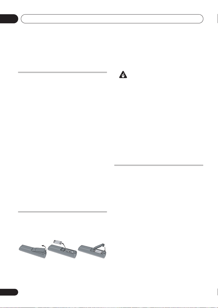
Loading the batteries
Use AA/R6 batteries with the supplied remote
control. Make sure to follow the indications (
) inside the compartment.
Important
Incorrect use of batteries may result in such
hazards as leakage and bursting. Observe the
following precautions:
• Never use new and old batteries together.
• Insert the plus and minus sides of the
batteries properly according to the marks
in the battery case.
• Batteries with the same shape may have
different voltages. Do not use different
batteries together.
• When disposing of used batteries, please
comply with governmental regulations or
environmental public instruction’s rules
that apply in your country or area.
Range of the remote control unit
The remote control has a range of about 7
meters (23 ft). It may not work properly if:
• There are obstacles between the remote
control and this unit’s remote sensor.
• Direct sunlight or fluorescent light is
shining onto the remote sensor.
• This system is located near a device that is
emitting infrared rays.
• This unit is operated simultaneously with
,
another infrared remote control unit.
6
En
Before you start
01
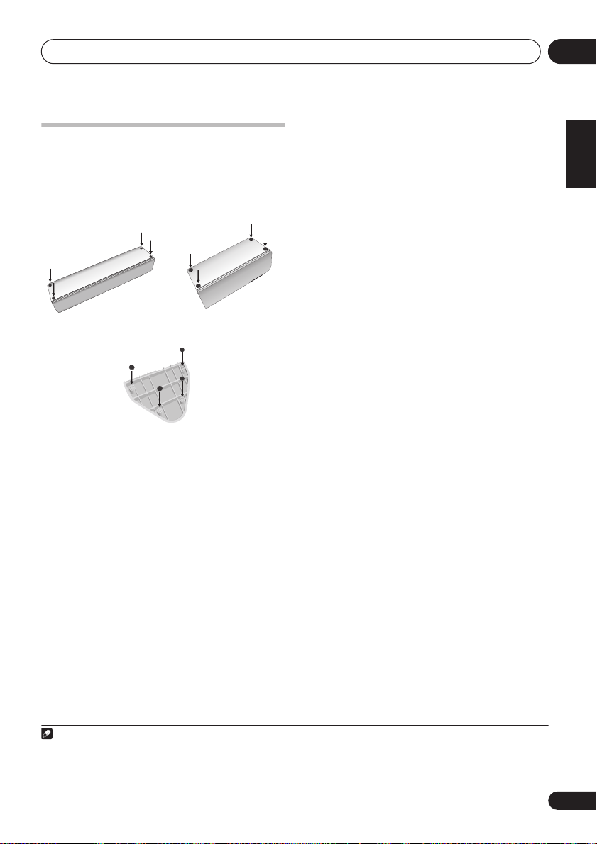
Attaching the non-skid pads
EV700/1000 model only
Use the self-adhesive non-skid pads to provide
a stable base for the speakers. Attach four to
each speaker or stand
Center speaker Surround speaker
Removing the front speaker grilles
If necessary, remove the front speaker grilles
as described below.
1 Gently ease the grille loose by gripping
the bottom and pulling towards you.
2 Pull the top free in the same way.
When reattaching, start from the top then push
the bottom in until secure.
• It is not recommended (due to dirt and
dust) to leave the speaker grilles removed.
• Since the speaker grilles may come loose,
make sure to place the speakers in a
location where they will not cause injury.
1
as shown below.
Speaker stands
English
Deutsch
Français
Italiano
Nederlands
Español
Note
1 If you choose to use the Front surround 3-spot setup (as explained in
to use the speaker stands provided (do not attach the pads to the base of the surround speakers). Using the speaker stands for
the Standard surround 5-spot setup is optional. See
on this.
Attaching the surround speakers to the speaker stands
Home theater sound setup
on page 23), it is necessary
on page 10 for more
7
En
Connecting up02
Chapter 2
Connecting up
Important
• Before making or changing any
connections, switch off the power and
unplug the power cord from the AC outlet.
• When making cable connections, make
sure not to bend the cables over the top of
this unit. This may cause a humming noise
from the speakers.
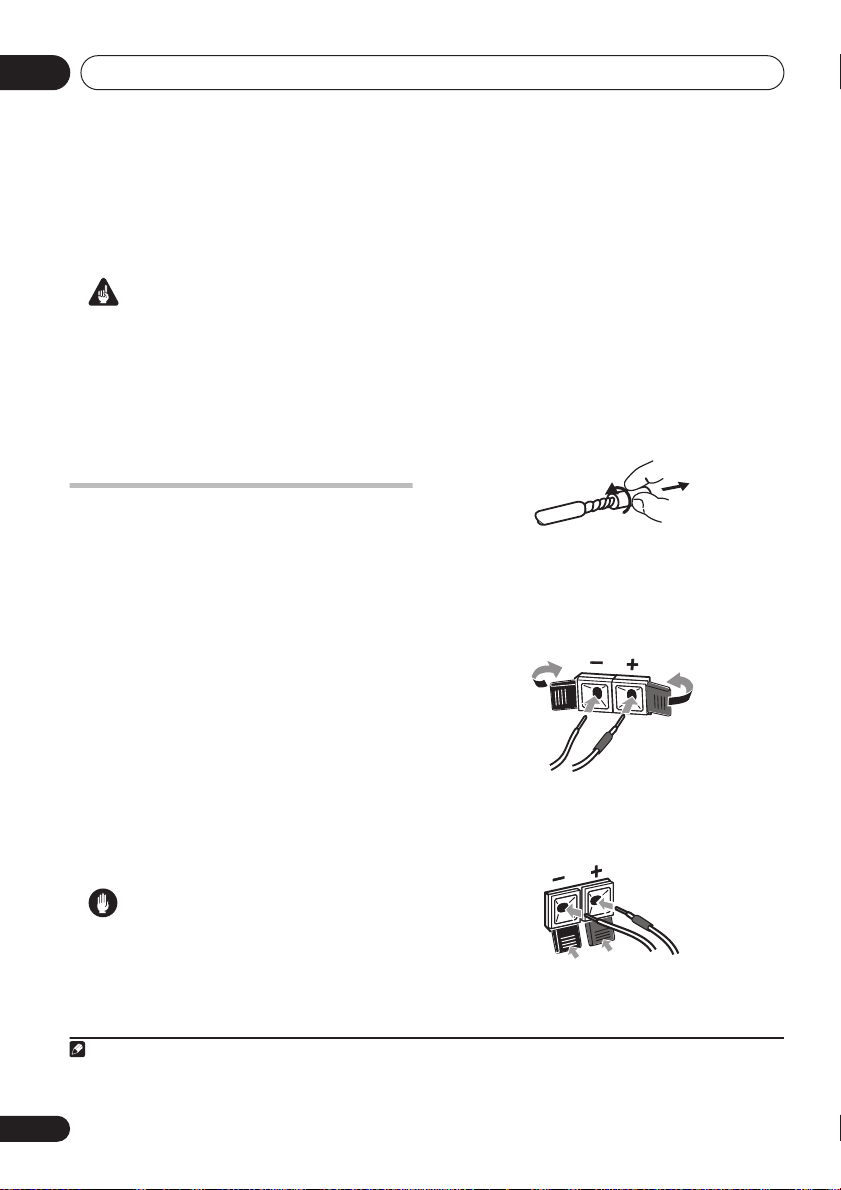
Connecting the speaker
terminals
Connect the wires from the speakers to the
terminals on the main unit rear panel as shown
below. Before connecting, you may want to
consider the placement options available in
your room, and when using this system:
•
EV500 model only –
right speakers at equal distances from the
TV, then connect them as shown below.
See
Optional surround speaker connections
on page 10 to connect surround speakers.
•
EV700/1000 model only –
system is provided for speaker connections
(see
Multichannel speaker connections
below). See
page 23 for surround placement options.
Place the front left and
A color-coded
Home theater sound setup
1
on
• Make sure that the bare speaker wires
cannot touch each other, or come into
contact with other metal parts once the
unit is switched on.
1 Twist and pull off the protective shields
on each wire.
2 Connect to the speaker terminals on the
rear of the unit.
Make sure to insert the red/colored wire into
the red/colored (+) tab and the black/white
wire into the black (–) tab.
3 EV 1000 only: Connect to the terminals on
the rear of the subwoofer and front speakers
in the same way.
Caution
• Do not connect this speaker to any amplifier
other than the one supplied with this
system. Connection to any other amplifier
may result in a malfunction or fire.
Note
1• The speakers supplied with this system are magnetically shielded. However, placing them extremely close to a television
may result in color distortion on the screen. If this happens, move the speakers a little further away and switch off the television
for 15–30 minutes.
8
En
Connecting up
02
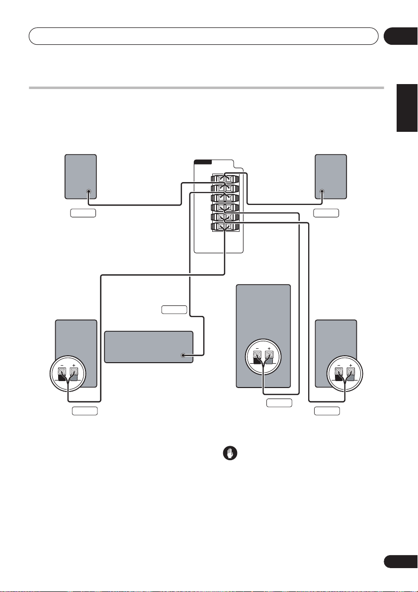
Multichannel speaker connections
EV700/1000 model only
Connect each speaker using the color-coded speaker cable. Match them to the colored labels
above the speaker terminals (see illustration below).
Surround right Surround left
Gray Blue
Front right*
Center
Green
EV700/1000DVD
SPEAKERS
L
SURROUND
R
CENTER
SUB
WOOFER
L
FRONT
R
Subwoofer*
Front left*
English
Deutsch
Français
Italiano
Nederlands
Español
*This connection is required only for the EV1000 model.
Hints on speaker placement
The following guidelines will help you to get the
best performance from your speaker system.
Home theater sound setup
See
on page 23 for
surround placement options with this system.
• Place the front left and right speakers at
equal distances from the TV.
• Place the center speaker above or below
the TV so that the sound of the center
channel is localized at the TV screen.
• If you choose to install the center speaker
• If possible, place the surround speakers
Purple
WhiteRed
Caution
on top of the TV, be sure to secure it with
putty, or by other suitable means, to reduce
the risk of damage or injury resulting from
the speaker falling from the TV in the event
of external shocks such as earthquakes.
slightly above ear level.
9
En
Connecting up02
• Try not to place the surround speakers
further away from the listening position
than the front and center speakers. Doing
so can weaken the surround sound effect.
• Be sure all speakers are installed securely
to prevent accidents and improve sound
quality.
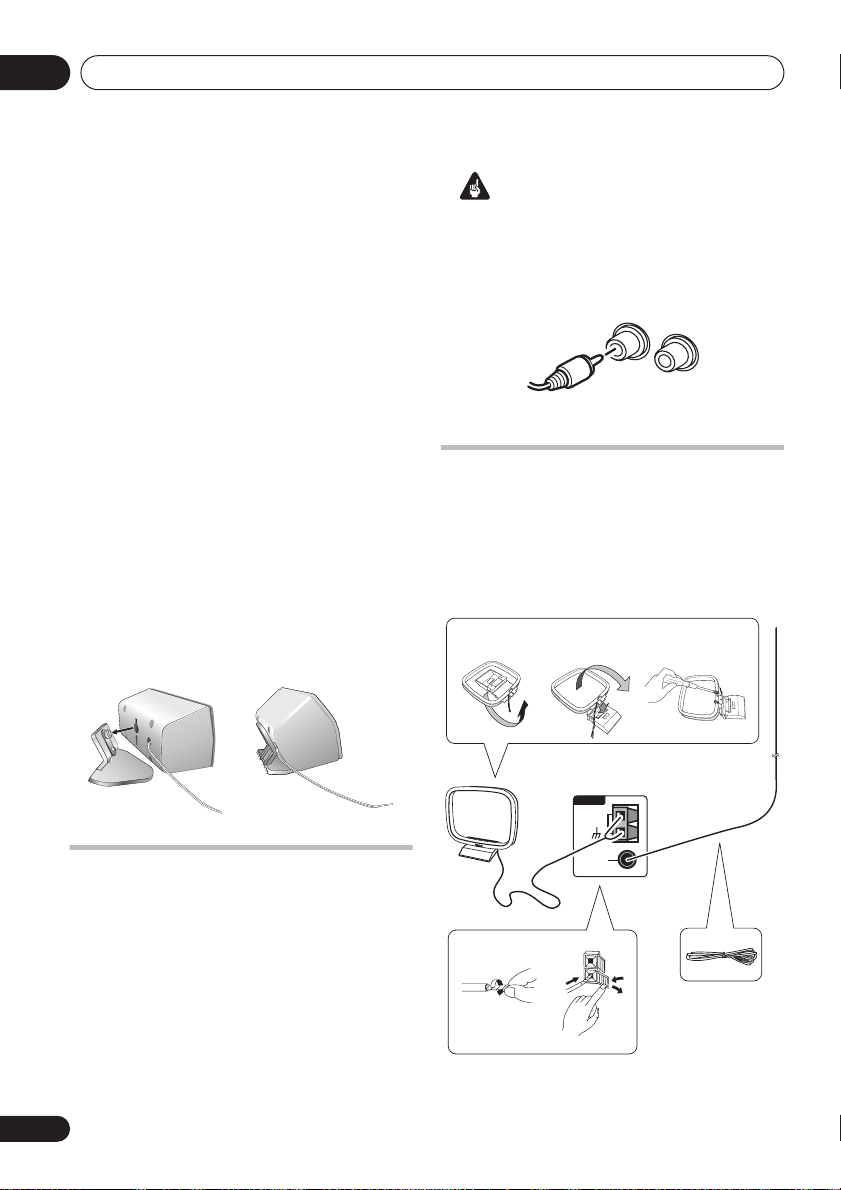
Attaching the surround speakers to
the speaker stands
EV700/1000 model only
If you have set up your system using the Front
surround 3-spot setup (as explained in
theater sound setup
on page 23), it is necessary
to use the speaker stands provided. Using the
speaker stands for the Standard surround 5spot setup is optional. Attach each speaker as
shown in the steps below.
1 Line up the spurs on the speaker stand
with the holes on the back of the surround
speaker and press into place.
2 With the spurs fixed in place, pull the
speaker downward to secure it on the stand.
12
Home
Important
• Use speakers with a nominal impedance of
Ω
at least 16
.
• Make sure you connect both surround
speakers or you won’t be able to hear
anything from the surround jacks.
R
L
SURROUND
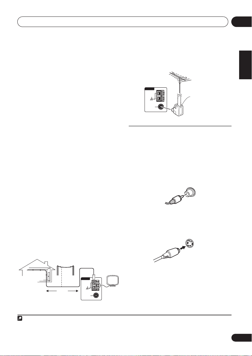
Connecting the radio antennas
Connecting the supplied antennas will allow
you to listen to both AM and FM radio
broadcasts. If you find that reception quality is
poor, an outdoor antenna should give you
better sound quality—see
antennas
below for more on how to do this.
fig. a fig. b fig. c
Connecting external
Optional surround speaker
connections
EV500 model only
Using RCA speaker cables, you can connect
surround speakers to the left and right
SURROUND
for multichannel sound from this system.
For the best surround effect, place the
surround speakers slightly above ear level and
at the same distance from the listening
position as the front speakers.
10
En
speaker jacks on the rear panel
ANTENNA
AM LOOP
ANTENNA
FM
UNBAL
4
75Ω
6
1
2
3
Connecting up
02
1 Pull off the protective shields of both AM
antenna wires.
2 Push open the tabs, then insert one wire
fully into each terminal, then release the tabs
to secure the AM antenna wires.
3 Fix the AM loop antenna to the stand.
To fix the stand to the antenna, bend in the
direction indicated by the arrow (
clip the loop onto the stand (
fig. b
fig. a
).
) then
• If you plan to mount the AM antenna to a
wall or other surface, secure the stand with
screws (
fig. c
) before clipping the loop to
the stand. Make sure the reception is clear.
4 Place the AM antenna on a flat surface
and point in the direction giving the best
reception.
Don’t let it come into contact with metal
objects and avoid placing near computers,
television sets or other electrical appliances.
1
5 Connect the FM wire antenna in the same
way as the AM loop antenna.
For best results, extend the FM antenna fully
and fix to a wall or door frame. Don’t drape
loosely or leave coiled up.
Connecting external antennas
External AM antenna
Use 5–6 meters of vinyl-insulated wire and set
up either indoors or outdoors. Leave the AM
loop antenna connected.
External FM antenna
Use a PAL connector to hook up an external
FM antenna.
ANTENNA
AM LOOP
ANTENNA
FM
UNBAL
75Ω
PAL connector
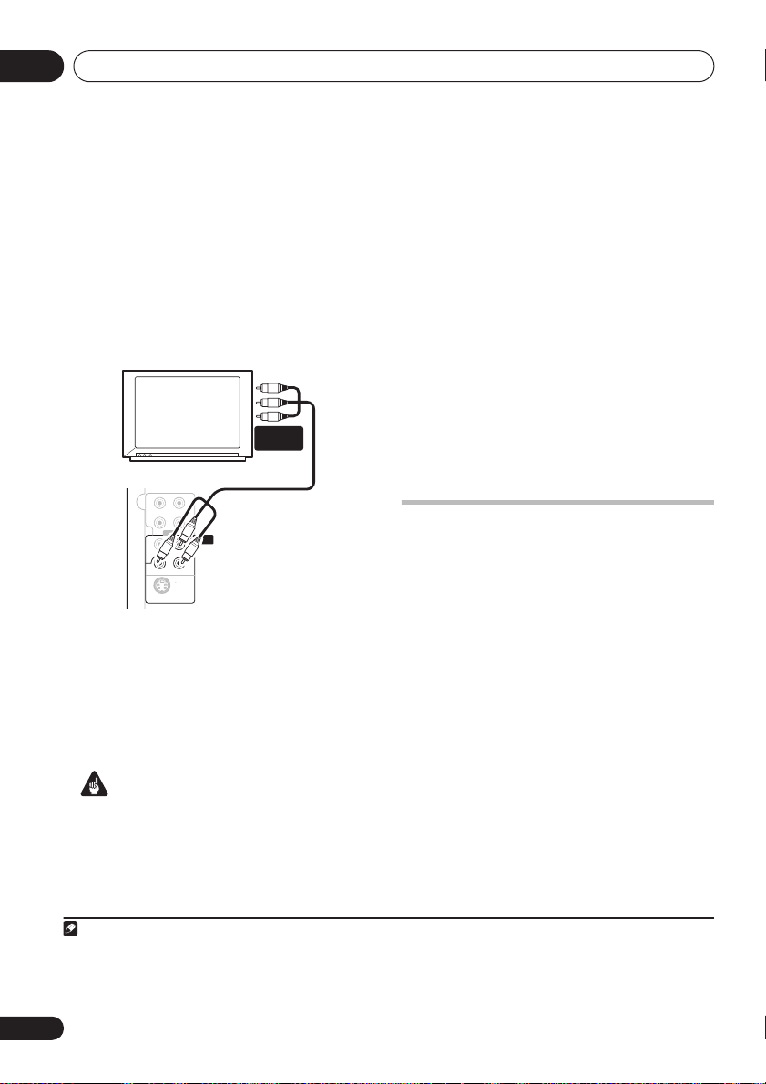
Connecting to your TV
This system offers three types of video
connections. If your TV has component video
inputs, see
video output
1 Use the supplied yellow video cable to
connect the VIDEO OUT jack to a video input
on your TV.
For a better image, you can also use a
commercially available S-Video cable to
connect the
input on your TV.
Connecting using the component
below.
VIDEO
OUT
S-VIDEO OUT
jack to an S-Video
S-VIDEO
OUT
English
Deutsch
Français
Italiano
Nederlands
Español
Outdoor antenna
2 Optionally: Use a stereo audio cable to
Indoor
antenna
(vinyl-coated
wire)
Note
1 The signal ground () is designed to reduce noise that occurs when an antenna is connected. It is not an electrical safety
ground.
5–6m
ANTENNA
AM LOOP
ANTENNA
FM
UNBAL
75Ω
connect the audio outs of your TV (or VCR) to
the LINE IN jacks on the rear of this unit.
This will enable you to hear the TV (or VCR)
sound through this system. See
auxiliary components
below for more on this.
Connecting
11
En
Connecting up02
panel
Connecting using the component
video output
If your TV has component video inputs, you can
use these instead of the standard or S-Video
output to connect this system to your TV.
should give you the best quality picture from
the three types of video output available.
• Use a component video cable to connect
the
COMPONENT VIDEO OUT
to a set of
component inputs on your TV.
COMPONENT
INPUT
L
L
CUT
IN
R
R
LINE
COMPONENT
VIDEO OUT
Y
VIDEO
OUT
PR PB
S VIDEO
OUT
About progressive scan video
Compared to interlace video, progressive scan
video effectively doubles the scanning rate of
the picture, resulting in a very stable, flickerfree image. Progressive scan video is available
only from the component video output.
Important
• If you connect a TV that is not compatible
with a progressive scan signal and switch
the system to progressive, you will not be
able to see any picture at all. In this case,
press
STANDBY/ON
to put the system
in standby, then press and hold the front
Note
1 The component video output is switchable between interlaced and progressive formats. See
2 Consumers should note that not all high-definition television sets are fully compatible with this product and may cause artifacts to be displayed in the picture. In case of 525 progressive scan picture problems, it is recommended that the user switch
the connection to the ‘standard definition’ output (Interlace). If there are questions regarding our TV set compatibility with this
model, please contact our customer service center.
1
This
Compatibility of this player with
progressive-scan and high-definition TVs.
This player is compatible with progressive
video Macro Vision System Copy Guard.
This system is compatible with the following
Pioneer displays and monitors: PDP-505HDG,
PDP-435HDG, PDP-5040HD, PDP4340HD,
PDP-502MX, PDP-503HDG, PDP-504HDG,
PDP-433HDG, PDP-434HDG, SD-532HD5,
SD533HD5.
Connecting auxiliary components
This system has both stereo analog inputs and
outputs. Use these to connect external
components, such as a VCR, MD, CD-R or DAT
recorder.
• Connect the LINE IN jacks on the rear
panel to an auxiliary playback component.
These include components such as a VCR,
DAT, or your TV. Connect using RCA pin-plug
stereo cables.
• Connect the LINE OUT jacks on the rear
panel to a recording component.
These include components such as a cassette
deck, VCR, MD recorder, or another recorder
with analog inputs. Connect using RCA pinplug stereo cables.
(stop) button for about 7 seconds
until the display shows
the front panel
the display shows
panel
button to set to interlace and
MEM.CLR?
or button so that
INTERL?
switch the system back on.
Video Output settings
. Press
. Press the front
2
on page 44.
12
En

Connecting up
02
Connecting the power
After making sure that everything is connected
properly, plug in the power cord to the AC inlet,
and the other end to a mains power outlet.
AC IN
Congratulations! You’re done setting up.
English
Deutsch
Français
Italiano
Nederlands
Español
13
En
Controls and displays03
Chapter 3
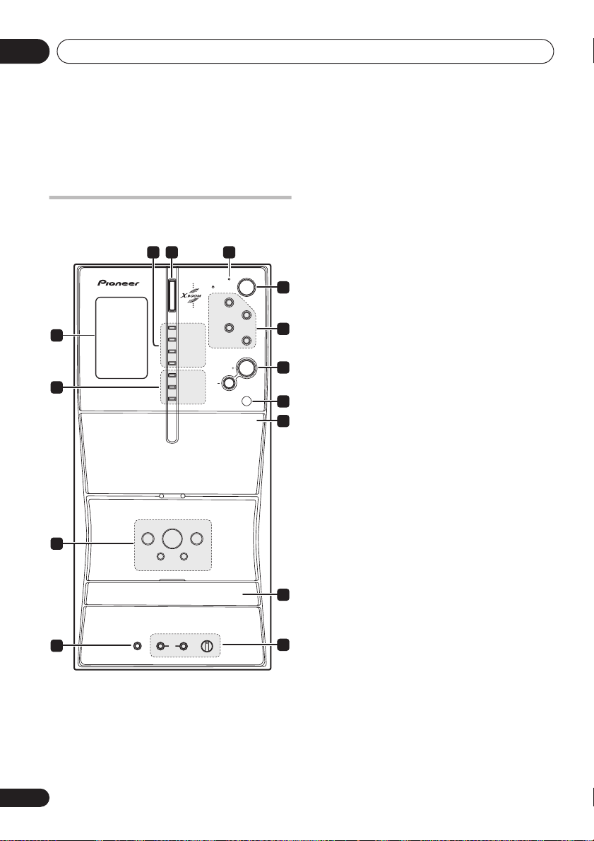
Controls and displays
SFC (EV500 only) – Selects sound modes or
Front panel
Illustration shows the EV700/1000 model
32
FRONT SURROUND
SOUND MODE
KARAOKE
ENTER
REVERSE MODE
REC/STOP
ASES
+–
TUNING
MS+/FF
MS–/REW
MAIN
MIC
14
13
12
1
PHONES SUB
1 Display
See Display below.
2 Sound options
FRONT SURROUND (EV700/1000 only) –
Switches on the Front Surround mode
(page 26).
4
TIMER
MUSIC
STANDBY/ON
DVD/CD
MOVIE
TAPE
TUNER
LINE
VOLUME
PUSH OPEN
MIC VOL
MIN MAX
5
6
7
8
9
10
11
custom settings from the Sound Field
Control (page 39).
SOUND MODE
Accesses settings in the Sound menu,
such as the tone controls (page 39).
KARAOKE – Selects audio channels for
karaoke (page 38).
ENTER – Selects options or executes
commands.
3
X.BOOM
button
Press to switch on the bass boost (page 39).
4
TIMER
indicator
Lights when the timer has been set (page 40).
5
STANDBY/ON
Switches the player on or into standby.
6 Function select buttons
Selects the source you want to listen to.
7
VOLUME +/–
Adjusts the volume level.
8 Remote sensor
PUSH OPEN
9
Pressing down on this side on the cassette
door will open the tape deck.
10 Disc tray
11
MIC VOL
and MIC input jacks
Controls the volume of the karaoke mics
(MAIN and SUB) (page 38).
12
PHONES
jack
Headphone jack.
14
En
Controls and displays
13
TUNING
and playback control buttons
The tuning/scan/skip buttons are used for
tuning into stations, skipping or scanning
tracks on discs or tapes. The playback control
buttons are used for playing, pausing and
stopping playback (
ejects the disc).
14 Tape cassette controls
REVERSE MODE
– Selects the playback
mode for tapes (page 34).
REC/STOP
– Starts/stops recording on the
tape deck (page 35).
ASES
– Press for CD-to-tape synchro
recording (page 35).
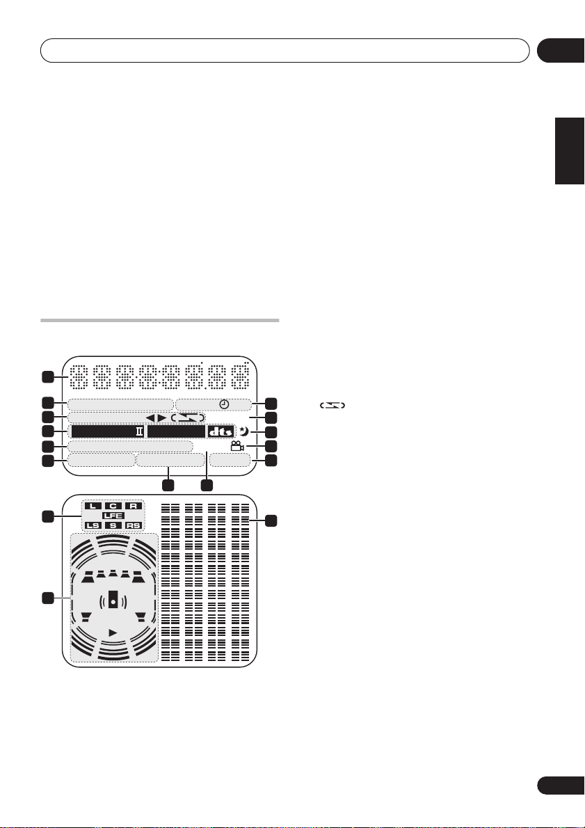
Display
1
2
ECHO
3
4
5
6
7
8
KEY KARAOKE L R WAKE–UP
B.CUT
ASES REC DIALOGUE
2
PRO LOGIC
MONO
STEREO TUNED 96kHz
ADV. SURR. SFC PGM RDM RPT–1 LINE REC
SUB
Wf
2
DIGITAL
9 10
1 Character display
2 Karaoke indicators
ECHO
– Lights when the Karaoke
effect is selected.
REC
ECHO
11
12
13
14
15
16
KEY
– Lights when the Karaoke pitch
control is selected.
KARAOKE
(Vocal cancel) – Vocals in the
backing track are partially eliminated using
EQ.
L
– Left channel only. Use for tracks that
have a vocal recorded in the right channel.
R
– Right channel only. Use for tracks that
have a vocal recorded in the left channel.
L R
– Use to put a single-channel vocal
track into the center of the mix.
3 Cassette deck indicators
B.CUT
– Lights when the beat cut mode
has been switched to
ASES REC
REC
– Lights during ASES recording.
– Lights when recording to the tape
B.CUT 2
.
deck.
– Indicates the direction of tape
playback.
– Indicates the reverse mode.
4 Format indicators
2 PRO LOGIC II
(EV700/1000 only) –
during Dolby Pro Logic II decoding.
2 DIGITAL
– Lights during playback of a
Dolby Digital signal.
DTS
– Lights during playback of a DTS
source.
5
Tuner indicators
MONO
– Lights when FM mono reception
is selected.
STEREO
– Lights when a stereo FM
broadcast is being received in auto stereo.
mode
TUNED
– Lights when a broadcast is being
received.
6 DSP indicators
ADV.SURR.
(EV700/1000 only)
Lights when one of the Advanced or Front
Surround listening modes is selected.
SFC
(EV500 only)
Lights when one of the Sound Field Control
listening modes is selected.
Lights
03
English
Deutsch
Français
Italiano
Nederlands
Español
15
En
Controls and displays03
7 Channel indicators
(EV700/1000 only)
These will light according to which channels
are encoded on the Dolby Digital or DTS
multichannel disc currently in the player.
LFE
lights when the disc has an LFE channel.
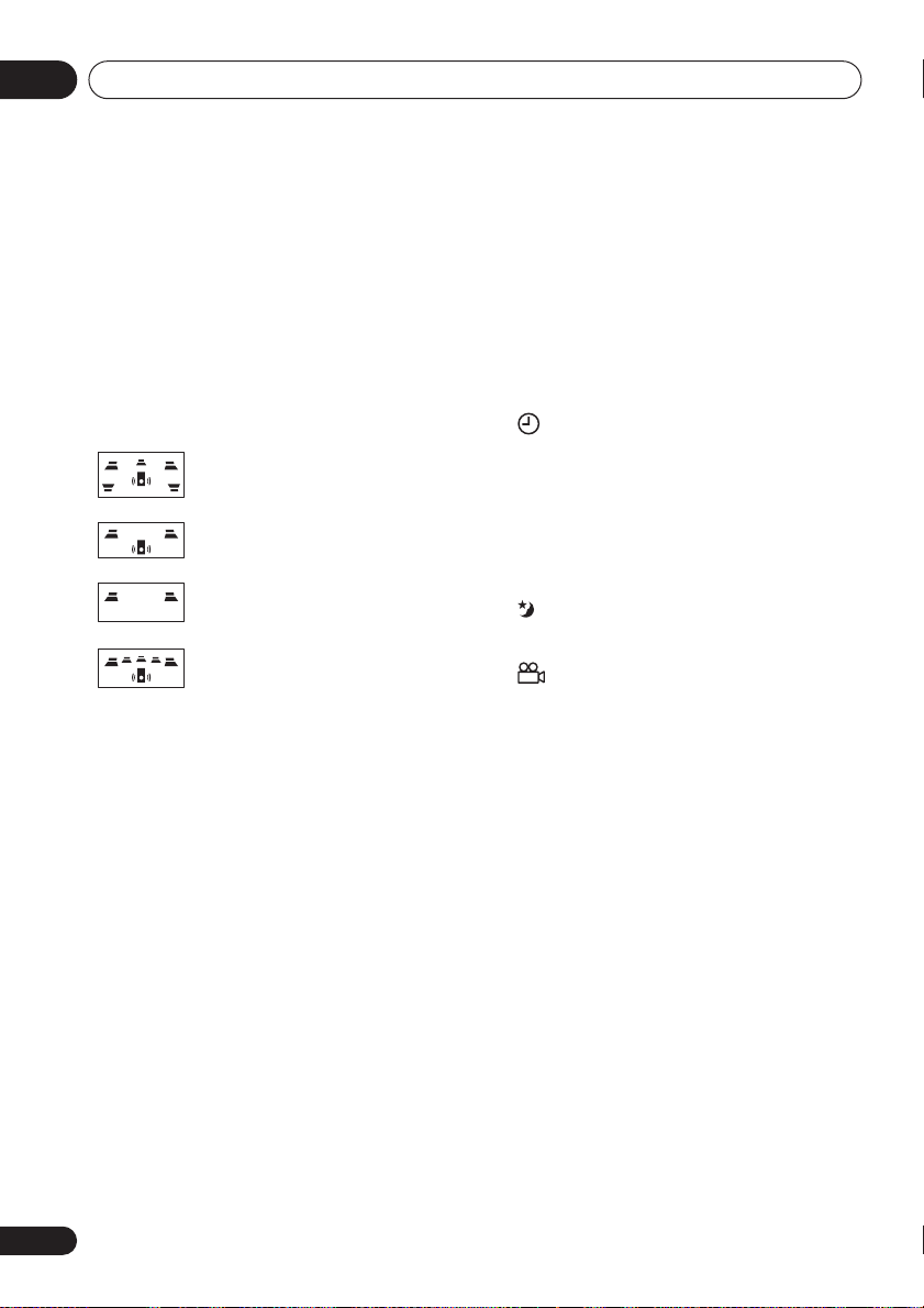
8 Speaker and playback indicators
The playback indicator () lights during playback,
and
the speaker indicators
(EV700/1000 only)
show which speakers are being used to output
the current source. The illustrations below
show some example displays.
5.1 channel surround sound
SUB Wf
SUB Wf
SUB Wf
Stereo (2.1 channel) sound
2 channel sound
5.1 channel surround sound
with the Front Surround mode
active
(When headphones are connected, none of the
speaker indicators are lit.)
9
Playback mode indicators
PGM
– Lights during program play
RDM
– Lights during random playback
RPT-1
–
RPT
lights during repeat play (
lights during repeat one-track play)
1
10 96 kHz
Lights when a 96kHz source is detected (may
not light if the source is copy–protected).
11 Timer indicators
WAKE-UP –
Lights when the wake-up
timer is set.
–
Lights when the wake-up timer is set
and flashes when it activates.
REC
– Lights when the record timer is set
and flashes when the timer starts
recording.
12 DIALOGUE
(EV700/1000 only)
Lights when Dialog Enhancement is on.
13
Lights when the sleep timer is active
14
Lights during multi-angle scenes on a DVD
15 LINE REC (EV700/1000 only)
Lights when the line recording mode is
switched on (see
Using the Sound menu
page 27).
16 Level meter
RPT-
on
16
En
Controls and displays
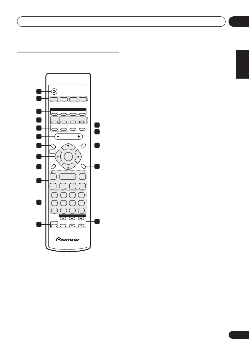
Remote control
Illustration shows the EV700/1000 model
STANDBY/ON
1
2
DVD/CD TAPE FM/AM LINE
DVD
AUDIO
SUBTITLE
—
KEYCON —
SURROUND
ECHO
8
REPEAT
MONO
CH LEVEL
INPUT
DSP
i
VOLUME
TUNE +
ENTER
TUNE –
3
3
3
TV CONTROL
ANGLE ZOOM
ADVANCED
DISPLAY MUTE
ST +ST –
7
RANDOM
TIMER
CHANNEL VOLUME
FRONT
SURROUND
TOP MENU
DVD MENU
RETURN
E/
¡
¢
CLEAR
ENTER
13
14
15
16
17
3
X.BOOM
4
I
KARAOKE
5
6
SYSTEM SETUP
7
HOME
MENU
8
SOUND
MODE
9
/e
1
10
4
PROGRAM
123
ST.MEMORY
11
456
TEST TONE
7890
SHIFT
12
1
STANDBY/ON
Switches the player on or into standby.
2 Input source function select
Selects the source you want to listen to.
3 DVD control buttons
AUDIO
– Selects the audio channel or
language (page 33).
SUBTITLE
– Selects a subtitle display
(page 33).
ANGLE
– Changes the camera angle
during DVD multi-angle scene playback
(page 33).
ZOOM
– Changes the zoom level
(page 33).
4 Sound Field / DSP buttons
X.BOOM
– Switches the bass boost on or
off (page 39).
SFC / SOUND FIELD
(EV500 only)
Selects sound modes or custom settings
from the Sound Field Control (page 39).
SURROUND (EV700/1000 only) –
Selects a
surround listening mode (page 25)
ADVANCED (EV700/1000 only) –
Selects an
advanced listening mode (page 26)
FRONT SURROUND
(EV700/1000 only) –
Switches on the Front Surround mode
(page 26).
5 KARAOKE controls
KARAOKE
– Selects audio channels for
karaoke (page 38).
ECHO
– Changes the echo level on the
karaoke mics (page 38).
KEY CONTROL
– Lowers/raises the pitch
of the backing track (page 38).
6 VOLUME
Adjusts the volume level.
7
HOME MENU
Press to display (or exit) the on-screen
menu for Initial Settings, Play Mode
functions, etc.
SYSTEM SETUP (SHIFT+HOME MENU
Use to make various system and surround
sound settings (page 48 and (
) page 24). Also used when
only
EV700/1000
automatically saving station presets when
using the tuner (page 37).
8
ENTER
, TUNE & cursor control buttons
Navigates on-screen displays and menus.
ENTER
selects an option or executes a
command.
03
English
Deutsch
Français
Italiano
Nederlands
Español
)
17
En

Controls and displays03
9 SOUND MODE
Accesses settings in the Sound menu, such as
the tone controls (page 39).
10 Playback controls
– Starts/resumes playback
and
/
– Use for reverse slow
motion playback, frame reverse and
reverse scanning
and / – Use for forward slow
motion playback, frame advance and
forward scanning
– Jumps to the next chapter or track
– Jumps to the beginning of the
current chapter or track, then to previous
chapters/tracks
– Pauses playback; press again to restart
– Stops playback
11 Number buttons and SHIFT functions
The number buttons can be used for selecting
tracks directly, the functions above the buttons
SHIFT
are accessed by pressing
at the same
time as the button.
PROGRAM (SHIFT+1
) – Use to program/
play a program list (page 31).
REPEAT (SHIFT+2
) – Selects a repeat play
mode (page 30).
RANDOM (SHIFT+3
) – Selects a random
play mode (page 31).
ST.MEMORY (SHIFT+4) –
Use for saving
and listening to station presets (page 37).
MONO (SHIFT+5) –
Press to listen to a
stereo FM broadcast in mono (page 22).
TIMER (SHIFT+6) –
Use for setting and
checking the clock (page 19) and the
timers (page 40).
TEST TONE (SHIFT+7) (EV700/1000 only) –
Press to output the test tone for speaker
setup (page 23).
CH LEVEL (SHIFT+8) (EV700/1000 only) –
Use to adjust the speaker level (page 23).
CLEAR
– Clears an entry
ENTER
– Selects menu options, etc. (works
exactly the same as the ENTER button in 8
above)
12 SHIFT
Press to access the functions/commands
written in green on the remote
13
MUTE
Mutes the volume (page 39).
14
DISPLAY
Switches between information displays
(page 33).
15
TOP MENU
Displays the top menu of a DVD disc.
DVD MENU
Displays the DVD menu (for Video CD/
Super VCDs, DivX video and WMA/MP3/
JPEG discs, the Disc Navigator screen
appears).
16
RETURN
Press to return to a previous menu screen.
17 TV CONTROL
1
– Switches the TV on or into standby
INPUT – Switches the TV input
CHANNEL +/– – Selects channels
VOLUME +/– – Adjusts the TV volume
Note
1 Refer to Setting up the remote to control your TV on page 19 to use these controls with your TV.
18
En
Getting started
3
04
Chapter 4
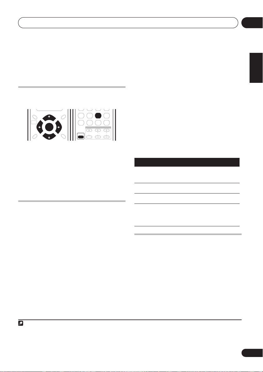
Getting started
3 Point the remote at your TV, hold down
Setting the clock
Setting the clock allows you to use the timer.
ST.MEMORY
MONO
SYSTEM SETUP
HOME
MENU
SOUND
MODE
1 Press
TUNE +
ENTER
TUNE –
TIMER
TOP MENU
DVD MENU
ST +ST –
RETURN
(SHIFT+6).
TIMER
CH LEVEL
INPUT
ENTER
TV CONTROL
CHANNEL VOLUME
456
TEST TONE
7890
SHIFT
2 If ‘CLK ADJ?’ isn’t in the display, select it
or , then press
with
3 Use
4 Use
ENTER
/
/
to confirm.
to set the hour. Press
to set the minute then press
ENTER
.
ENTER
Setting up the remote to control
your TV
You can set up the supplied remote to control
your TV using the
TV CONTROL
buttons.
1 Switch on your TV.
2 Find the name of the manufacturer of
your TV in the Preset Code List on page 60.
Next to each manufacturer is one or more
three digit codes. These tell the remote what
kind of TV you have.
If the name of the manufacturer of your TV
does not appear in the table, you won’t be able
to set up this remote to control your TV.
2
the CLEAR button, then enter the three
digit code for your TV.
1
The remote transmits an on/off signal to the TV.
If you’ve entered the correct code, your TV
should switch off.
If your TV doesn’t turn off, repeat the procedure
using the next code in the list until your TV
switches off successfully. Once set, you can
then use the individual TV controls shown
below.
Button
.
CHANNEL +/–
VOLUME
INPUT
Using the on-screen displays
For ease of use, this system makes extensive
use of graphical on-screen displays (OSDs).
All the screens are navigated in basically the
same way, using the cursor buttons (
pressing
What it does
Switches your TV on or into
standby.
Changes the TV channel.
Adjusts the volume.
Switches the TV’s input
between the built in TV tuner
and an external video source.
, ,
) to change the highlighted item and
ENTER
to select it.
3
English
Deutsch
Français
Italiano
Nederlands
Español
,
Note
1 The default setting is 12-hour format. See
2• The default setting is for a Pioneer TV.
• Note that there are also cases where the codes listed for a manufacturer in the Preset Code List may not work for your TV.
3 The screen saver will appear after five minutes of inactivity.
Optional system settings
on page 48 to change it.
19
En
 Loading...