


AUDIO/VIDEO MULTI-CHANNEL RECEIVER
VSX-D1011-S VSX-D1011-K VSX-D1011-G
Operating Instructions

NOTE: THE NO USER-SERVICEABLE PARTS COMPARTMENT WARNING IS LOCATED ON THE APPLIANCE BONNET
Thank you for buying this Pioneer product. Please read through these operating instructions so you will know how to operate your model properly. After you have finished reading the instructions, put them away in a safe place for future reference.
Installing the Receiver
VENTILATION: When installing this unit, make sure to leave space around the unit for ventilation to improve heat radiation (at least 60 cm at top, 10 cm at rear, and 30 cm at each side).
WARNING: Slot and openings in the cabinet are provided for ventilation and to ensure reliable operation of the product and to protect it from overheating, to prevent fire hazard, the openings should never be blocked and covered with items, such as newspapers, tablecloths, curtains, etc. Also do not put the apparatus on the thick carpet, bed, sofa, or fabric having a thick pile.
2
En
TWO VOLTAGE SELECTOR SWITCHES (multi-voltage model only)
Only multi-voltage model is provided with these switches. Mains voltages in Saudi Arabia are 127 V and 220 V only. Never use this model with the 110 V setting in Saudi Arabia.
Only multi-voltage model is provided with this(these) switch(switches).
European models are not pro-vided with these switches.
The line voltage selector switches are on the rear panel. Check that they are set properly before plugging the power cord into the household wall socket. If the voltage is not properly set or if you move to an area where the voltage requirements differ, adjust the selector switches as follows.
1.Use a medium-size screwdriver.
2.First, insert the screwdriver in the groove of the larger voltage selector, and adjust so that the tip of the groove points to the voltage value of your area.
3.Next, insert the screwdriver in the groove of the amaller voltage selector and adjust until the voltage is the same as at the larger one.
TWO VOLTAGE SELECTORS
220V |
230 |
110V |
120−127V 240V |
110V |
220V |
120-127V |
230-240V |
CAUTION 220 V
Power source voltage is factory adjusted 220 volts. If your area is different, change voltage selectors settings.
Operating Environment
Operating environment temperature and humidity:
+5°C – +35°C (+41°F – +95°F); less than 85%RH (cooling vents not blocked)
Do not install in the following locations
•Location exposed to direct sunlight or strong artificial light
•Location exposed to high humidity, or poorly
ventilated location
[For European model]
3
En

Table of Contents
Features ................................................. |
6 |
Before You Start .................................... |
7 |
Checking the Supplied Accessories ........................... |
7 |
Preparing the Remote Control .................................... |
7 |
Loading the batteries ............................................. |
7 |
Operating range of remote control unit ............... |
8 |
Installing the Receiver ................................................. |
8 |
Opening the Front Panel ............................................. |
8 |
Easy Setup Guide Part 1 ....................... |
9 |
Home Theater: The Basics .......................................... |
9 |
1) Your Home System ............................................ |
9 |
2) The Source Material ........................................... |
9 |
3) The Listening Modes .......................................... |
9 |
Conclusion .............................................................. |
9 |
1 Hooking Up Your DVD Player & TV ..................... |
10 |
Digital Connections .............................................. |
10 |
2 Speaker Connections ........................................... |
11 |
3 Setting up the Main Unit ...................................... |
12 |
4 Assigning the Digital Inputs ................................ |
12 |
Easy Setup Guide Part 2 ..................... |
13 |
1 QUICK Setup ......................................................... |
13 |
2 Playing a DVD with Surround Sound ................. |
14 |
Connecting Your Equipment .............. |
15 |
Connecting your TV ................................................... |
15 |
Connecting Video Components ................................ |
16 |
Connecting a DVD player ..................................... |
16 |
Connecting VCRs or DVRs ................................... |
17 |
Connecting a Video Component |
|
to the Front Panel ................................................. |
17 |
Connecting Satellite TV (SAT) Components ...... |
18 |
Connecting Analog Audio Components .................. |
19 |
Connecting to the Multi Channel Analog Inputs |
|
(DVD-Audio or Super Audio CD (SACD) compatible |
|
player) ............................................................................. |
20 |
Connecting Digital Audio Components ................... |
21 |
Digital Input Default Settings .............................. |
22 |
Connecting the Radio Antennas ............................... |
23 |
Using outdoor antennas ...................................... |
23 |
Connecting Speakers ................................................. |
24 |
Speaker impedance .............................................. |
25 |
Placing Your Speakers ............................................... |
26 |
Speaker placement ............................................... |
26 |
AC Power Cord ........................................................... |
26 |
AC Outlet [switched 100W max] |
|
(European model only) .............................................. |
26 |
Displays & Controls ............................ |
27 |
Display ........................................................................ |
27 |
Front Panel ................................................................. |
28 |
Remote Control .......................................................... |
30 |
Back Panel .................................................................. |
32 |
Setting Up for Surround Sound ........ |
34 |
SURRBACK SYSTEM (Surround Back System) ...... |
35 |
NORMAL setup .......................................................... |
36 |
SPEAKER SETTING .............................................. |
37 |
CHANNEL LEVEL (channel balance) ................... |
39 |
CHANNEL DELAY ................................................. |
40 |
Basic Operation ................................... |
41 |
Stereo and Multichannel Playback ........................... |
41 |
Switching ANALOG/DIGITAL Signal Input ......... |
42 |
Listening Modes ........................................................ |
43 |
STEREO modes ..................................................... |
43 |
MOVIE modes (SURROUND mode) .................... |
44 |
MUSIC modes (SURROUND mode) .................... |
45 |
Adjusting the Effect of a Listening Mode ........... |
46 |
Adding/Adjusting the Effect in |
|
Dolby Pro Logic II Music Mode ........................... |
46 |
Listening with ACOUSTIC CALIBRATION EQ .......... |
47 |
Reducing Noise During Playback |
|
(DIGITAL NR Function) .............................................. |
47 |
Listening in MIDNIGHT Mode ................................... |
48 |
Listening in LOUDNESS Mode ................................. |
48 |
Adjusting Bass and Treble (TONE CONTROL) ........ |
49 |
Listening in HI–BIT/SAMPLING Mode ...................... |
50 |
DVD-Audio/MULTI CHANNEL IN Playback .............. |
50 |
SB CH MODE button .................................................. |
51 |
SB CH MODE ......................................................... |
51 |
VIRTUAL SURROUND BACK Mode ..................... |
51 |
DUAL MONO setting and Playback .......................... |
52 |
Using Headphones .................................................... |
52 |
Video Select ............................................................... |
53 |
Adjusting the Brightness of the Display |
|
(DIMMER) ................................................................... |
53 |
Using the Tuner ................................... |
54 |
Automatic and Manual Tuning ................................. |
54 |
MPX Mode ............................................................ |
54 |
RF ATT Mode (European model only) ................ |
54 |
Channel Step Setting (multi-voltage model only) ... |
55 |
To Change Channel Steps |
|
(multi-voltage model only) .................................. |
55 |
Direct Access Tuning ................................................. |
55 |
Memorizing Frequently Used Stations .................... |
56 |
Naming Memorized Stations .................................... |
57 |
Recalling Memorized Stations .................................. |
58 |
4
En

Table of Contents
An introduction to RDS (European model only) ..... |
59 |
Using the RDS display ......................................... |
59 |
Searching for RDS programs |
|
(European model only) .............................................. |
60 |
Basics of EON (Enhanced Other Network |
|
information) (European model only) ....................... |
61 |
Using EON (European model only) .......................... |
61 |
Clearing all stations from |
|
the RDS or EON search (European model only) ..... |
62 |
Remote Control of Other |
|
Components ........................................ |
63 |
Setting Up the Remote Control to Control Other |
|
Components ............................................................... |
63 |
Recalling Settings Stored in the |
|
Remote Control ..................................................... |
63 |
Programming Signals from Other Remote |
|
Controls (LEARNING Mode) ................................ |
64 |
Using Remote Control with Other Components ..... |
65 |
CD/MD/CD-R/VCR/DVD/LD/DVD Recorder/ |
|
Cassette Deck operations ..................................... |
65 |
Cable TV/ Satellite TV/ |
|
Digital TV/ TV operations ..................................... |
66 |
Setting up the DIRECT FUNCTION ........................... |
67 |
Using Other Functions ........................ |
68 |
Recording from Audio/Video Components ............. |
68 |
SECOND ZONE (Speaker System B)/FRONT BI-AMP |
|
Setup ........................................................................... |
69 |
Stereo playback in another room (SECOND |
|
ZONE) .................................................................... |
69 |
Bi-amping the front speakers |
|
(FRONT BI-AMP) ................................................... |
69 |
A/B Speaker Button .............................................. |
70 |
Connecting Additional Amplifiers ............................ |
71 |
Multi Operations ........................................................ |
72 |
Performing Multi Operations ............................... |
73 |
SYSTEM OFF .............................................................. |
74 |
Using SYSTEM OFF .............................................. |
75 |
The PIONEER SR System: Operating other PIONEER |
|
components ............................................................... |
75 |
Resetting the Remote Control .................................. |
76 |
Erasing Multi Operations ..................................... |
76 |
Erasing Learned Remote Control Commands ... |
76 |
Erasing All Remote Control settings ................... |
76 |
Resetting the Main Unit ............................................ |
77 |
Fine Tuning Your System ................... |
78 |
Other System Settings .............................................. |
78 |
THX CINEMA Setup ................................................... |
79 |
Assigning the Digital Inputs ...................................... |
80 |
FUNCTION RENAME ................................................. |
81 |
Expert Setup ............................................................... |
82 |
CROSSOVER NETWORK ...................................... |
83 |
FINE CHANNEL LEVEL ......................................... |
84 |
FINE CHANNEL DELAY ........................................ |
85 |
ACOUSTIC CAL EQ ............................................... |
87 |
BASS PEAK LEVEL ............................................... |
89 |
DYNAMIC RANGE CONTROL .............................. |
90 |
Techno Tidbits & Problem-solving ..... |
91 |
Dolby ........................................................................... |
91 |
Dolby Digital ......................................................... |
91 |
Dolby Pro Logic II ................................................. |
91 |
Dolby Digital Surround EX .................................. |
92 |
DTS ............................................................................. |
92 |
DTS ........................................................................ |
92 |
DTS-ES .................................................................. |
92 |
DTS Neo:6 ............................................................. |
92 |
DTS 96/24 .............................................................. |
92 |
THX ............................................................................. |
93 |
Speaker Placement Information ............................... |
94 |
Preset Code List ......................................................... |
96 |
Troubleshooting ......................................................... |
98 |
Schemata of Setup .................................................. |
103 |
Specifications (European model) ........................... |
104 |
Specifications (multi-voltage model) ...................... |
105 |
SETUP EASY GUIDE
PREPARATION SURROUNDSETUP
BASIC
EXPERT
5
En
Features
High Quality, Balanced Multichannel Design
The VSX-D1011 receiver is constructed with Pioneer’s industry-leading advanced and well balanced multichannel Featuresconcept. This means it is designed to reproduce music and movie soundtracks as close as possible to the intentions of the producer during mastering. The receiver uses a revolutionary 3-D Frame
Construction technique and a Symmetrical Power Train Design, with high-performance Advanced Direct Energy
MOS-FET output devices, generating 100 watts of power for 7 independent channels.
Multichannel Acoustic Calibration EQ System (MCACC)
In order to make setting up as easy as possible for users we have created the MCACC system. This unique and convenient way of getting good surround sound from the receiver makes trouble-free set up a snap. The MCACC system creates a monitoring environment to establish the parameters of the sound in regards to each speaker for the specific room you are using. The Acoustic Calibration EQ feature makes sure each speaker is used to maximum effect in conjunction with the overall sound. The resulting settings finely attune the overall surround sound for the space used.
Dolby Digital EX, DTS-ES, DTS 96/24 and the Latest Audio and Video Formats
The VSX-D1011 is equipped with Dolby Digital EX decoding, the very latest Dolby Digital contribution to home theater with surround back speakers in addition to surround speakers. These additional speakers make home theater even more realistic and powerful. Naturally, you can also play all existing audio formats, including the recently developed Dolby Pro Logic II and DTS-ES Extended Surround formats on the VSX-D1011 as well. On the video side, the component video output is fully compatible with high definition, progressive-scan digital video (720p).
Lucasfilm and THX are trademarks or registered trademarks of Lucasfilm, Ltd. & TM. Surround EX is a jointly developed technology of THX and Dolby Laboratories, and is a trademark of Dolby Laboratories. All rights reserved. Used under authorization.
Manufactured under license from Dolby Laboratories. “Dolby”, “Pro Logic”, “Surround EX” and double-D symbol are trademarks of Dolby Laboratories.
"DTS", "DTS-ES Extended Surround" and "Neo:6" are trademarks of Digital Theater Systems, Inc.
Universal Player Compatibility (DVD Audio/Super Audio CD [SACD])
This receiver incorporates the latest technology and is able to handle cutting edge audio formats, like DVD Audio and Super Audio CD (SACD) which are just hitting the market. Its high compatibility offers a variety of inputs to decode all types of sources at the highest possible quality. The receiver’s multichannel input connections lets you hook up eight discrete channels of audio.
Audio Scaler (HI BIT/HI SAMPLING)
This new technology enables the user to hear CD and DVD, as well as other soundtracks at a wider dynamic range, allowing for finer audio reproduction. This Audio Scaler approximates the audio of high end formats just becoming available now.
Easy-to-use Remote Control
This new remote control is extremely convenient to use. One button is dedicated to one task in the control of the receiver, eliminating confusing buttons whose purpose are unclear. In addition, this remote can be used to operate a variety of other components simply by recalling the appropriate setup codes.
The Energy-saving Design
The European model is designed to use 0.7 W of energy when the receiver is in standby mode, while the multivoltage model is designed to use 0.9 W.
6
En
Before You Start
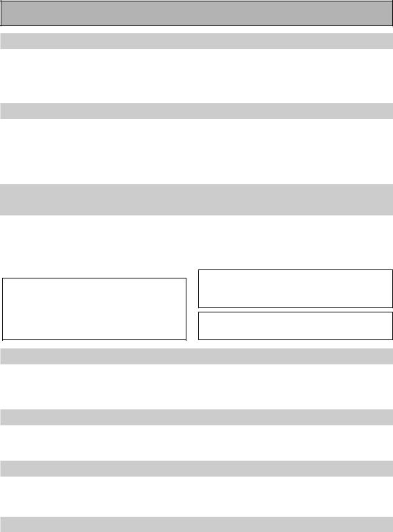
Checking the Supplied Accessories
Please check that you have received all of the following supplied accessories.
AM Loop Antenna
|
|
|
|
|
|
|
|
|
|
DVD/LD |
RECEIVER |
|
|
|
|
|
|
|
|
|
|
|
|
|
|
OPERATION |
|
|
|
|
|
|
|
|
|
|
|
|
|
|
|
MULTI |
|
|
|
|
|
|
|
|
|
|
|
VCR |
TVMULTI |
OFFSYSTEM |
|
||
|
|
|
|
|
|
|
|
|
MOVIE |
2 |
/SAT |
CONTROL |
SOURCE |
|
|
|
|
|
|
|
|
|
|
CD |
|
|
|||
|
|
|
|
|
|
|
|
STEREO/ MODESURROUND |
MUSIC |
|
VCR1/DVR |
|
||
|
|
|
|
|
|
|
|
TUNER |
TV |
|
||||
|
|
|
|
|
|
|
|
DIRECT |
|
MODECH |
ACOUSTICEQ |
RECEIVER |
CONT |
|
|
|
|
|
|
|
|
|
ENTER |
|
|
|
|||
|
|
|
|
|
|
|
|
|
|
SB |
INPUT |
|
|
|
|
|
|
|
|
|
MENU |
|
|
|
|
|
|
||
|
|
|
|
|
|
TUNER |
VOLUMEMASTER |
MIDNIGHT |
MULTI |
|
|
|
||
|
|
|
|
|
SETUPSYSTEM |
INPUTCH |
|
|
|
|||||
|
|
|
|
|
|
EDIT |
|
|
|
|
|
|
||
|
|
|
AUDIO |
ST |
|
TUNE |
ON |
|
MUTE |
|
|
|
|
|
|
|
|
|
|
|
|
|
TEXT |
|
|
|
|
|
|
|
|
CHANNEL |
|
|
ENTER |
|
TOP |
|
|
|
|
|
||
|
|
|
|
|
|
MENU |
|
|
|
|
|
|||
|
|
|
− |
|
TUNE |
|
ST |
GUIDE |
|
|
|
|
|
|
|
|
RF |
TEXT |
|
|
|
|
|
|
|
|
|||
|
|
ATT |
|
|
|
|
|
|
|
|
|
|||
|
DIMMER |
D. |
OFF |
|
|
RETURN |
|
|
|
|
|
|
||
|
ACCESS |
|
BAND |
|
|
|
|
|
|
|
||||
|
SIGNAL |
LOUDNESS |
|
MPX |
|
CHANNEL+ |
|
|
|
|
|
|
|
|
|
SEL |
|
|
|
|
|
|
|
|
|
|
|
||
|
VIDEO |
DNR |
TONE |
|
CLASS |
|
|
|
|
|
|
|
|
|
SELINPUT |
SEL |
|
|
|
|
|
|
|
|
|
|
|||
TV |
BASS/TREBLE |
EFFECT/CH |
|
|
|
|
|
|
|
|
|
|
||
|
HI |
|
|
|
|
|
|
|
|
|
|
|
|
|
|
-BIT |
|
|
|
|
|
|
|
|
|
|
|
|
|
ECT |
CONTROL |
|
ENTER |
SEL |
|
|
|
|
|
|
|
|
|
|
|
+ |
DISC |
|
|
|
|
|
|
|
|
|
|
|
|
|
CHANNEL |
+ |
|
|
|
|
|
|
|
|
|
|
|
|
|
|
− |
|
|
|
|
|
|
|
|
|
|
|
|
|
VOLUME |
10 |
|
|
|
|
|
|
|
|
|
|
|
|
|
SUB |
|
|
|
|
|
|
|
|
|
|
|
|
|
|
|
TITLE |
|
|
|
|
|
|
|
|
|
|
|
|
|
SETUPREMOTE |
|
|
|
|
|
|
|
|
|
|
|
|
|
RECEIVER 

FM Wire Antenna
AUDIO/VIDEO MULTI-CHANNEL
RECEIVER
VSX-D1011-S
VSX-D1011-K
VSX-D1011-G
Operating Instructions
Operating
Instructions
“AA” IEC LR6 batteries x 2
AC Power Cord x 2 (multi-voltage model only)
memo Multi-voltage model has two power cords. These accessories will be different depending on the  country of purchase. Please use the correct cord for your country.
Preparing the Remote Control
Loading the batteries
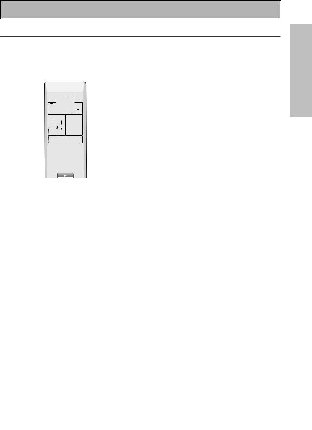
Load the batteries into the remote control as shown below. Please use alkaline batteries. When you notice a decrease in the operating range, replace all batteries with new ones.
1 2 “AA” IEC LR6 3
batteries x 2
CAUTION!
Incorrect use of batteries may result in such hazards as leakage and bursting. Observe the following precautions.
•Never use new and old batteries together.
•Insert the plus and minus sides of the batteries properly according to the marks in the battery case.
•Batteries with the same shape may have different voltages. Do not use different batteries together.
•When disposing of used batteries, please comply with governmental regulations or environmental public institution’s rules that apply in your country or area.
PREPARATION
7
En
Before You Start
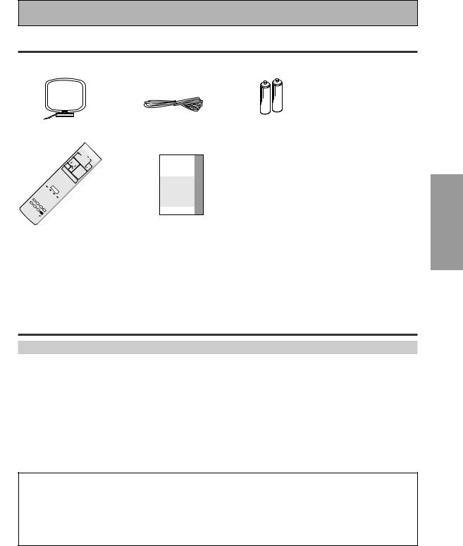
Operating range of remote control unit
The area in which you can use the remote control to operate the VSX-D1011 is fairly large. To use, point the remote control toward the remote sensor on the front panel of this unit while within the range shown below.
Remote control may not function properly if:
•There are obstacles between the remote control and the remote sensor.
•Direct sunlight or fluorescent light is shining onto the remote sensor.
•The receiver located near a device emitting infrared rays.
•Operated simultaneously with another remote control which uses infrared rays.
30 

30
7m
Installing the Receiver
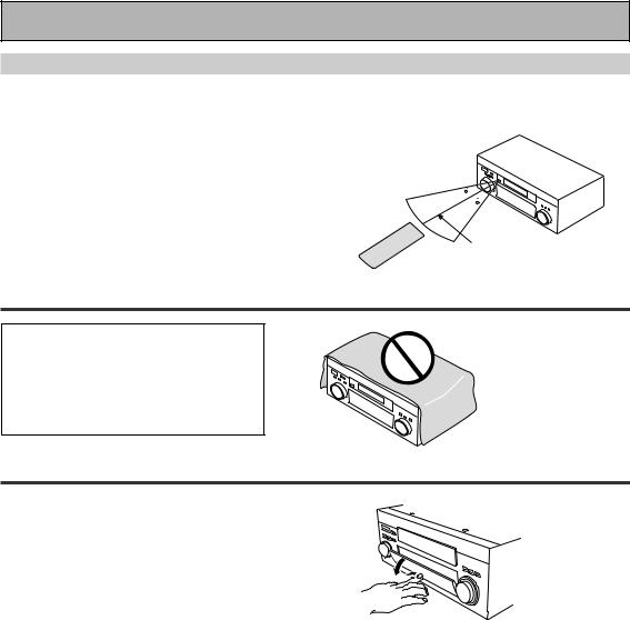
CAUTION!
•Do not cover this unit in any way, for example with a sheet or piece of cloth. This would prevent proper heat dispersal.
• Do not any place object directly on top of this unit. This also would prevent proper heat dispersal.
Opening the Front Panel
To open the front panel push gently on the lower third of the panel with your finger.
8
En

Easy Setup Guide Part1
Home Theater: The Basics
Most consumers are used to using stereo equipment to listen to music but many people are not used to home theater systems that give you many more options when listening to soundtracks. In fact, home theater is not really complicated and this little guide should give you an understanding of the basics. Home theater refers to the use of multiple audio tracks combined with multiple speakers to create a surround sound effect.
There are three different factors involved in getting surround sound. Each contribute to what kind of sound you get. These factors are:
1)The equipment you are using for your home theater setup. Particularly important is the number of speakers you are using. We call this your speaker configuration.
2)The source material you are using. This is the actual product (like a DVD) or broadcast (like cable TV) you are listening to/watching. We call this the source.
3)The last factor is the listening mode you choose on the VSX-D1011 receiver. These are explained below and in subsequent chapters but most likely the PRO LOGIC II MOVIE for moves and the PRO LOGIC II MUSIC for music will be fine.
Let's start with the home theater setup you have in your home.
1)Your Home System
The heart of your system is the VSX-D1011 receiver and it is very flexible in getting you theater-like surround sound. You can use this receiver with anywhere from two to seven speakers (front left, front right, center, surround left and right, and surround back left and right) and a subwoofer to get home theater surround sound. We recommend you use seven speakers and a subwoofer. If this is not possible follow the instructions in "QUICK Setup" in the "Easy Setup Guide Part 2" and you will still be able to get good surround sound. Also, a DVD player is essential for home theater and you can also hook up satellite or cable TV tuner to this receiver and get a more home theater-like sound from these sources.
2) The Source Material
DVDs have become the basic source material for home theater because they are convenient to use and offer excellent sound and picture quality as well as allow users to enjoy home theater soundtracks with more than two channels of audio. For example, Dolby Pro Logic plays back four channels (front left, front right, center and a single channel for both surround speakers), Dolby Digital and DTS sources usually have six discrete channels (front left, front right, center, surround left and right and a channel that powers the subwoofer) of sound. Since the subwoofer channel is only for bass sounds it is expressed as .1 of a channel and this multichannel setup has been named 5.1 channel sound.
It is important you consult the manual that came with your DVD player as well to make sure the player is outputting a surround soundtrack and all the other settings are appropriate for your home theater.
3) The Listening Modes
This receiver has many different listening modes and they are designed to cover all the speaker configurations and types of sources you might be using. In general, the PRO LOGIC II MOVIE listening mode is the easiest way to get realistic surround sound for movies. For music the basic listening mode for music is PRO LOGIC II MUSIC.
To listen to music in stereo simply choose the STEREO listening mode. Other possibilities (like listening to a stereo CD with all seven speakers or taking a stereo source and getting multichannel home theater-like sound) are explained in listening modes (pages 43–45).
Conclusion
These are the three basic factors that contribute to your home theater sound. The easiest thing is to hook up seven speakers and a subwoofer and simply play your DVDs with PRO LOGIC II MOVIE listening mode. This will give you realistic and enjoyable home theater sound. First hook up your equipment, like your DVD player, TV and speakers. Then follow the Easy Setup Guide instructions to set up your system for surround sound. It is very important you do one of the surround sound setups to get optimal sound from your receiver.
For more details on any of the information presented here check the main section of the manual.
SETUP EASY GUIDE
PREPARATION
9
En
Easy Setup Guide Part1
Before making or changing the connections, switch off the power and disconnect the power cord from the AC outlet.
1 Hooking Up Your DVD Player & TV
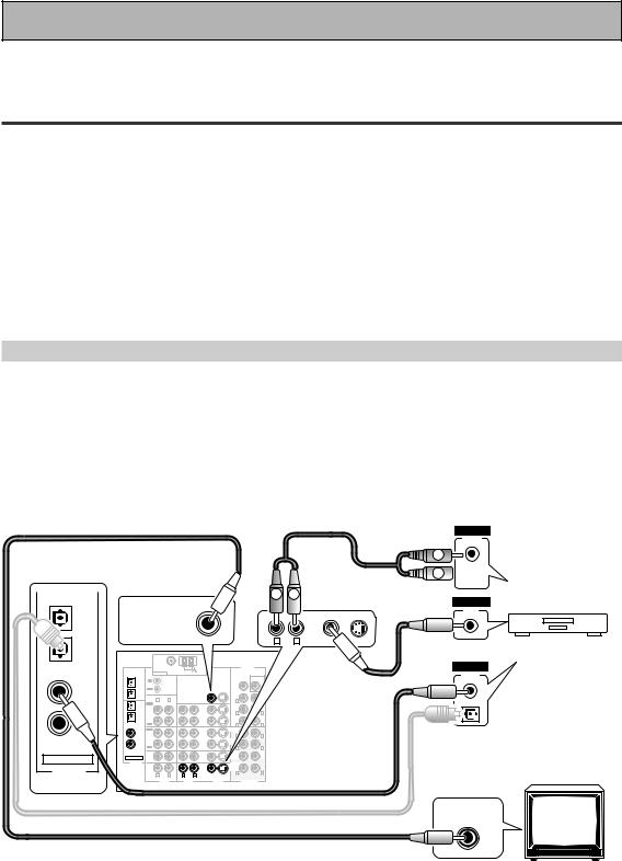
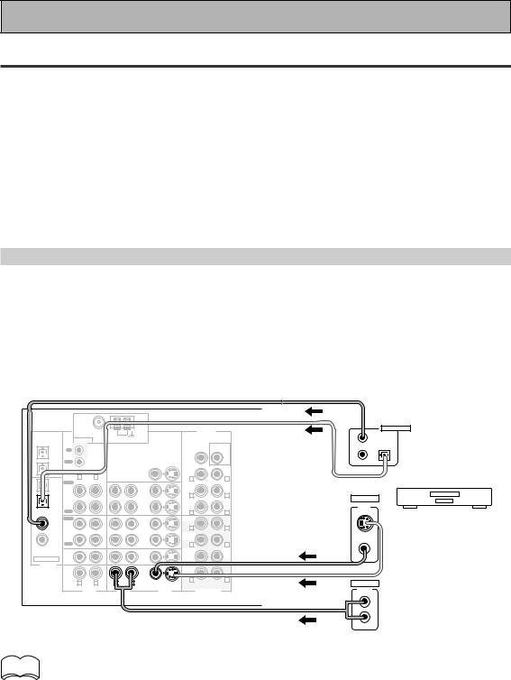
In order to use Dolby Digital/DTS soundtracks, which are at the heart of home theater, you need to hook up your DVD player with digital audio connections. You can do this by either a coaxial or an optical connection, you don’t need to do both. The quality of these two types of connections is the same but since some DVD players only have one type of digital terminal you need to figure out which yours has and hook it up to the appropriate terminal on the receiver. In order to do this you will need the proper cable. For coaxial connections you can use a regular RCA video cord or the specially-made coaxial cords, they have the same type of plugs. For optical connections you will need a special optical cable which you can buy at your local stereo store. For more information on cords and cables see page 21. You should also hook up your DVD player with analog audio connections. Use regular RCA stereo cords for these connections. Also hook up the video connection on your DVD player, and your TV to this receiver. For your TV it's easiest to use a regular composite (RCA) video cord, as shown below. S Video and Component video cords are of higher quality than RCA video cords and may also be used with this unit.
Digital Connections
Some DVD players have both coaxial and optical terminals, but there is no need to connect both. If your DVD player has a coaxial terminal (not a PCM-only output) for the audio out hook it up using this terminal. Follow the diagram below. This is the best scenario, as you will be able to follow the default settings of this receiver and won't need to assign the digital inputs (you should use DIGITAL IN 3).
If your DVD player only has an optical terminal for the audio output you can hook it up using one of the DIGITAL IN terminals between 1-2 (for example, DIGITAL IN 2). In this case, you will need to assign the digital input (which means tell the receiver which input you used for your DVD digital audio). See page 12 for this.
RCA video cord |
RCA stereo cord |
L
ANALOG
AUDIO
L
R  R
R
IN 1 |
(TV/ |
SAT) |
IN 2 |
(CD-R/ |
TAPE1) |
IN 3 |
(DVD/ |
LD) |
IN 4 |
(CD) |
ASSIGNABLE |
DIGITAL |
|
|
|
|
|
|
R |
L |
|
|
|
|
VIDEO |
|
|
|
|
|
|
|
|
|
|
|
|
|
|
|
|
|
|
|
|
|
|
|
|
|
VIDEO |
|
|
|
|
|
|
|
|
|
|
|
|
OUT |
MONITOR OUT |
|
|
|
|
|
DVD/ |
|
|
|
|
|
|
|
|
|
|
|
|
|
LD |
|
|
|
|
|
|
|
|
|
|
|
|
IN |
|
|
|
|
|
|
|
|
|
|
|
R |
L |
VIDEO |
S VIDEO |
|
|
DVD player |
|
|
|
|
|
|
|
|
|
|
|
|
|
PCM/ |
FM UNBAL 75Ω |
|
|
|
PRE OUT |
|
|
|
|
|
DIGITAL |
|
2DIGITAL / |
ANTENNA |
|
AM LOOP |
|
|
|
|
|
|
|
|
OUTPUT |
|
|
|
|
|
|
|
AC OUTLET |
|
||||
DTS/MPEG |
|
|
|
|
|
SUB |
|
|
|
|||
|
CONTROL |
|
|
CENTER |
WOOFER |
RCA video cord |
|
|
||||
OUT1 |
IN |
|
|
|
|
|
|
|
|
|
|
|
|
OUT |
|
|
|
|
|
|
|
|
|
|
|
OUT2 |
|
|
|
|
FRONT |
|
|
|
|
|
|
|
SAT) |
IN |
|
MONITOR OUT 1 |
ROUND |
|
|
|
|
|
|
(not a PCM-only |
|
|
|
IN |
|
|
|
|
|
|
||||
IN 1 |
R |
L |
|
|
R |
L |
|
|
|
|
|
|
PLAY |
|
|
|
SUR- |
|
|
|
|
|
|
|
|
(TV/ |
|
|
|
|
|
|
|
|
|
|
|
|
IN 2 |
CD-R/ |
|
|
VCR1/ |
R |
L |
|
|
|
|
|
output) |
(CD-R/ |
REC |
|
|
OUT |
BACKR |
L |
|
|
|
|
|
|
TAPE1 |
|
|
DVR |
SUR- |
(Single) |
|
|
|
|
|
|
|
TAPE1) |
OUT |
|
|
|
ROUND |
|
|
|
|
|
|
|
IN 3 |
PLAY |
|
|
|
FRONT |
|
SPEAKERS |
SURROUND BACK / |
ı |
|
||
(DVD/ |
IN |
|
|
IN |
|
|
Å |
FRONT |
CENTER |
SURROUND |
|
R |
|
|
R |
L |
SURROUNDRF ONT L |
CENTERSURROUNDR |
L L |
|
|||||
LD) |
MD/ |
|
|
VCR2 |
|
LL |
R BACKR L |
|
|
You only need to make |
||
(CD) |
REC |
|
|
|
R |
L |
|
|
|
|
|
|
IN 4 |
TAPE2 |
|
|
|
SUR- |
|
ª |
|
|
|
ª |
|
OUT |
|
|
OUT |
ROUND |
|
|
|
ª |
|
|||
|
CD |
|
|
TV/ |
SUB |
CEN- |
|
|
|
|
|
one DIGITAL connection. |
ASSIGNABLE |
IN |
|
|
SAT |
WOOF- |
TER |
|
|
|
|
|
|
|
|
IN |
ER |
|
|
|
|
|
|
|
||
DIGITAL |
LINE |
|
|
DVD/ |
SUR- |
|
|
|
|
|
|
|
|
|
|
|
ROUND |
|
· |
|
|
|
· |
|
|
|
IN |
|
|
LD |
BACK |
|
|
|
· |
|
||
|
|
|
IN |
L |
|
|
|
|
|
|||
|
R |
L |
R |
L |
R |
|
|
|
|
|
|
|
|
|
|
|
|
VIDEO S VIDEO |
|
|
coaxial cord |
|
|
||
|
AUDIO |
|
AUDIO |
|
VIDEO |
MULTI CH IN |
|
|
|
|||
optical cord
VIDEO INPUT
10
En
Easy Setup Guide Part1
2 Speaker Connections
Home theater is designed to be setup with five, or seven speakers (front left & right; center; surround left & right; and, optimally, surround back left & right) and a subwoofer, but you can use this receiver with fewer speakers. Hook up the speakers you have to the A speaker terminals on the back of the receiver. If you only have two speakers hook them up as FRONT. If you have three hook up the single speaker as CENTER. Follow the diagram below in order to hook up all your speakers. A center speaker is very important for watching films because in digital soundtracks the dialog comes from the center speaker. If you do not have a center speaker you must tell the receiver the center channel is off or when you listen to digital soundtracks you won't hear any dialog. This can be easily accomplished by following the steps in the Surround Sound QUICK setup instructions from page 13 in this Easy Setup Guide.
If possible, use surround back speakers. These speakers are important to take full advantage of all the sound channels on new, eight channel home theater DVDs. The diagram below also explains how to hook up a subwoofer which provides realistic bass sounds. For the subwoofer use a mono (single plug) RCA cord and for the other speakers use regular speaker cords. See pages 94–95 for advice on speaker placement.
Make sure you connect the speaker on the right to the R terminal and the speaker on the left to the L terminal. Also make sure the positive and negative (+/–) terminals on the receiver match those on the speakers.
|
|
|
|
|
Powered |
|
|
|
|
|
|
|
|
|
|
||
|
Front |
|
|
|
subwoofer |
TV/monitor |
|
|
|
|
|
Front |
|
|
|
||
|
|
|
|
|
|
|
|
|
|
|
|
|
|
|
|||
|
speaker |
|
|
|
|
|
|
|
|
|
|
|
|
speaker |
|
|
|
|
(Left) |
|
|
|
|
|
|
|
|
|
|
|
|
(Right) |
|
|
|
|
|
|
|
|
|
|
|
|
Center |
|
|
|
|
|
|
|
|
|
|
|
|
|
|
|
|
|
speaker |
|
|
|
|
|
|
|
|
|
|
|
|
|
|
INPUT |
|
|
|
|
|
|
|
|
|
|
|
Surround |
|
|
FM UNBAL 75Ω |
|
|
|
|
PRE OUT |
|
|
|
|
|
|
|
|
|
speaker |
2DIGITAL / |
|
AM LOOP |
|
|
|
|
|
|
|
|
|
|
|
|
||
ANTENNA |
|
|
|
|
|
|
|
|
|
|
|
|
|
||||
|
PCM/ |
|
|
|
|
|
|
|
|
|
|
|
|
|
|
|
|
(Left) |
DTS/MPEG |
IN |
|
|
|
|
CENTER |
WOOFER |
|
|
|
|
|
|
|
AC OUTLET |
Surround |
OUT1 |
|
|
|
|
|
|
|
|
|
|
|
||||||
|
|
|
|
|
|
|
|
SUB |
|
|
|
|
|
|
|
|
speaker |
|
|
OUT |
CONTROL |
|
|
|
|
|
|
|
|
|
|
|
|
|
|
|
OUT2 |
|
|
MONITOR OUT 1 |
|
FRONT |
|
|
|
|
|
|
|
|
|
(Right) |
|
|
IN 1 |
R |
L |
|
|
|
R |
L |
|
|
|
|
|
|
|
|
|
|
PLAY |
|
|
|
|
|
|
|
|
|
|
|
|
|
|||
|
|
|
|
|
SUR- |
|
|
|
|
|
|
|
|
|
|
||
|
(TV/ |
|
|
|
|
|
|
|
|
|
|
|
|
|
|
|
|
|
SAT) |
IN |
|
|
IN |
|
ROUND |
|
|
|
|
|
|
|
|
|
|
|
|
|
|
|
R |
L |
|
|
|
|
|
|
|
|
|
||
|
IN 2 |
CD-R/ |
|
|
VCR1/ |
|
|
|
|
|
|
|
|
|
|
||
|
(CD-R/ |
TAPE1 |
|
|
DVR |
|
SUR- |
(Single) |
|
|
|
|
|
|
|
|
|
|
TAPE1) |
OUT |
|
|
OUT |
|
ROUND |
|
|
|
|
|
|
|
SWITCHED 100W MAX |
|
|
|
|
|
|
|
BACK |
|
|
|
|
|
|
|
|
||||
|
|
REC |
|
|
|
|
R |
L |
SPEAKERS |
|
|
|
|
|
|
|
|
|
IN 3 |
PLAY |
|
|
|
|
FRONT |
|
|
|
|
|
SURROUND BACK / ı |
|
|||
|
|
|
|
|
|
Å |
|
FRONT |
|
CENTER |
R SURROUND L |
|
|||||
|
(DVD/ |
IN |
|
|
IN |
|
R |
L |
R |
L |
R |
L |
|
||||
|
LD) |
MD/ |
|
|
VCR2 |
|
|
|
|
|
|
|
|
|
|
||
|
IN 4 |
TAPE2 |
|
|
|
|
SUR- |
|
ª |
|
|
|
|
|
|
ª |
|
|
OUT |
|
|
OUT |
|
ROUND |
|
|
|
|
|
|
|
|
|||
|
(CD) |
|
|
|
|
|
|
|
|
|
|
|
|
|
|
||
|
|
REC |
|
|
|
|
R |
L |
|
|
|
|
|
|
|
|
|
|
|
CD |
|
|
TV/ |
|
SUB |
CEN- |
|
|
|
|
|
|
|
|
|
|
|
IN |
|
|
SAT |
|
WOOF- |
TER |
|
|
|
|
|
|
|
|
|
|
ASSIGNABLE |
|
|
IN |
|
ER |
|
|
|
|
|
|
|
|
|
|
|
|
DIGITAL |
LINE |
|
|
DVD/ |
|
SUR- |
|
|
|
|
|
|
|
|
|
|
|
|
|
|
|
|
ROUND |
|
· |
|
|
|
|
|
|
· |
|
|
|
|
IN |
|
|
LD |
|
BACK |
|
|
|
|
|
|
|
|
||
|
|
|
|
IN |
|
R |
L |
|
|
|
|
|
|
|
|
|
|
|
|
R |
L |
R |
L |
|
|
|
|
|
|
|
|
|
|
||
|
|
VIDEO |
S VIDEO |
|
|
|
|
|
|
|
|
|
|
||||
|
|
|
|
|
|
|
|
|
|
|
|
|
|
|
|
||
|
|
|
AUDIO |
AUDIO |
|
VIDEO |
MULTI CH IN |
|
|
|
|
|
|
|
|
|
|
Surround back |
Surround back |
speaker (Left) |
speaker (Right) |
memo |
• We recommend speakers with a nominal impedance rated 8 Ω-16 Ω, but you can change the |
|
speaker impedance setting of the receiver (see page 25). |
||
|
•If you only have one surround back speaker hook it up to the left surround back terminal.
•If you use a THX certified subwoofer use the THX INPUT jack on the subwoofer (if your subwoofer has one) or switch the filter position to THX on your subwoofer.
•When you attached your speaker wire to the speaker terminal make sure that not even one strand of wire touches the back of the receiver. If this happens it could short out the receiver.
7 Speaker terminals
1 Twist exposed wire |
2 Loosen speaker terminal |
3 Tighten |
strands together |
and insert exposed wire. |
terminal. |
tightly. |
|
|
10mm
SETUP EASY GUIDE
11
En

Easy Setup Guide Part1
3 Setting up the Main Unit
1Plug the AC power cord into a wall outlet.
2Press the –OFF-ON button to put the receiver in ON mode.
3Press the  STANDBY/ON button to switch the receiver ON.
4 Assigning the Digital Inputs
This is only necessary if you did not hook up your DVD player to DIGITAL IN 3 using a coaxial cable but rather connected it to one of the optical digital inputs. The following example shows how to assign the DIGITAL IN 2 jack to DVD. Use the arrow buttons (5∞) and the ENTER button on the remote control to navigate the display on the receiver. Conversely, you can use the MULTI JOG dial and ENTER button on the front panel.
|
RECEIVER MULTI |
SYSTEM |
SOURCE |
|
|
|
OPERATION |
OFF |
|
|
|
MULTI CONTROL |
|
|
|
DVD/LD |
TV/SAT |
VCR1/DVR |
TV CONT |
|
VCR 2 |
C D |
TUNER |
RECEIVER |
|
MOVIE |
MUSIC |
ACOUSTIC |
INPUT |
|
EQ |
|||
|
SURROUND |
SB CH |
MULTI CH |
|
|
MODE |
MODE |
INPUT |
|
|
STEREO/ |
ENTER |
MIDNIGHT |
|
|
DIRECT |
|
||
|
|
|
|
MUTE |
|
|
MASTER |
|
|
2,7 |
|
VOLUME |
|
|
MENU TUNER EDIT |
TEXT ON |
TOP MENU |
||
SETUP |
TUNE |
|
|
|
|
SYSTEM |
|
|
GUIDE |
|
ST |
ST |
||
|
|
ENTER |
|
|
|
AUDIO |
|
|
RETURN |
|
|
TUNE |
|
|
|
CHANNEL− |
TEXT OFF |
BAND |
CHANNEL+ |
1
3-6
4DIGITAL-IN should be selected, if not use the 5∞ buttons to select
it. Press the ENTER button.
SIGNAL |
dB |
ANALOG
SB CH
ON MOVIE
AUTO OFF MUSIC
SP A B
5 Use the 5∞ buttons to select
DIGI-2: CD-R and press ENTER.
SIGNAL |
dB |
ANALOG
SB CH
ON MOVIE
AUTO OFF MUSIC
SP A B
When you press ENTER, CD-R blinks.
1Turn on the receiver, press the RECEIVER button on the remote control.
2Press the SYSTEM SETUP
button.
SIGNAL |
dB |
ANALOG
SB CH
ON MOVIE
AUTO OFF MUSIC
SP A B
This display appears on the receiver.
3Looking at the display on your receiver, use the 5∞ buttons to select INPUT ASSIGN. Press the
ENTER button.
SIGNAL |
dB |
ANALOG
SB CH
ON MOVIE
AUTO OFF MUSIC
6 Use the 5∞ buttons to select
DVD/LD and press ENTER.
SIGNAL |
PRO |
dB |
AUTO |
|
|
RF |
DTS |
|
DIGITAL |
|
|
ANALOG |
|
|
SB CH
ON MOVIE
AUTO OFF MUSIC
SP A B
7 Press the SYSTEM SETUP button.
The receiver exits the setup process.
SP A B
12
En
Easy Setup Guide Part2
1 QUICK setup
With this QUICK setup you can quickly and easily adjust the speakers settings so that you get enjoyable surround sound with minimum effort.
You must have front and surround speakers hooked up to use this setup.
You only need to do these settings once (unless you change the placement of your current speaker system or add new speakers, etc.).
|
RECEIVER MULTI |
SYSTEM |
SOURCE |
|
|
|
OPERATION |
OFF |
|
|
|
MULTI CONTROL |
|
|
|
DVD/LD |
TV/SAT |
VCR1/DVR |
TV CONT |
|
VCR 2 |
C D |
TUNER |
RECEIVER |
|
MOVIE |
MUSIC |
ACOUSTIC |
INPUT |
|
EQ |
|||
|
SURROUND |
SB CH |
MULTI CH |
|
|
MODE |
MODE |
INPUT |
|
|
STEREO/ |
ENTER |
MIDNIGHT |
|
|
DIRECT |
|
||
|
|
|
|
MUTE |
|
|
MASTER |
|
|
2,8 |
|
VOLUME |
|
|
MENU TUNER EDIT |
TEXT ON |
TOP MENU |
||
SETUP |
TUNE |
|
|
|
|
SYSTEM |
|
|
GUIDE |
|
ST |
ST |
||
|
|
ENTER |
|
|
|
AUDIO |
|
|
RETURN |
|
|
TUNE |
|
|
|
CHANNEL− |
TEXT OFF |
BAND |
CHANNEL+ |
1
3-7
In each mode, the current settings are displayed automatically. We suggest you adjust all these settings when you first hook up the receiver.
SUBWOOFER setting:
If you connected a subwoofer select YES, if you didn’t select NO.
CENTER SP setting:
If you connected a CENTER speaker select YES, if you didn’t select NO.
SURRBACK SP setting:
If you connected a SURROUND speaker(s) select YES, if you didn’t select NO.
1Press the RECEIVER button on the remote control.
2Press the SYSTEM SETUP
button.
SIGNAL |
dB |
ANALOG
SB CH
ON MOVIE
AUTO OFF MUSIC
SP A B
This display appears on the receiver.
3SURROUND SETUP should be selected, if not use the 5∞ buttons to select it. Press the ENTER button.
4Use the 5∞ buttons to select
QUICK. Press the ENTER button.
SIGNAL |
dB |
ANALOG
SB CH
ON MOVIE
AUTO OFF MUSIC
SP A B
ROOM SIZE setting:
Tell the receiver your room size so it can equalize the speakers properly. Use the chart below for an approximate definition of the settings.
S: 2.5 m by 3.5 m M: 4 m by 5 m
L: 5.5 m by 7.5 m
LISTENING POSITION setting:
This setting establishes where your ideal listening position is. Choose from the three possibilities following the guide below.
FRONT: your listening position is closer to the front speakers.
CENTER: your listening position is equidistant from the front and surround speakers.
REAR: your listening position is closer to the surround speakers.
6In a menu use the 5∞ buttons to select the different settings. When you have the setting you want in a particular menu, press
ENTER.
SIGNAL |
dB |
ANALOG
SB CH
ON MOVIE
AUTO OFF MUSIC
SP A B
5Use the 5∞ buttons to navigate through the QUICK setup menus. When you get a menu you want
to adjust press ENTER.
SIGNAL |
dB |
ANALOG
SB CH
ON MOVIE
AUTO OFF MUSIC
7Repeat steps 5 and 6 to change other menus.
8Press the SYSTEM SETUP
button.
The receiver exits the setup process.
SP A B
SETUP EASY GUIDE
When ENTER is pressed, the setting for each |
13 |
selected menu blinks. |
En
Easy Setup Guide Part2
2 Playing a DVD with Surround Sound
1Make sure the receiver, your TV, your subwoofer and your DVD player are switched ON.
2Press the DVD/LD button on the remote control.
You should see DVD/LD in the display on the receiver.
3 Play a DVD then adjust the MASTER VOLUME.
memo To get a more refined sound, make the sound settings in "Expert setup" (starting on page  82).
82).
If you're having trouble getting surround sound playback look at this Frequently Asked Questions (FAQ) guide:
Q1: Even though I'm playing a DVD I'm not getting 5.1 channel playback.
A1: Either the DVD is not set for digital output, or the Dolby Digital/DTS output settings are not correct.
Set the DVD player to output a digital signal and set the Dolby Digital and DTS output properly. If you are unsure how to do this check the DVD initial setup in the manual that came with your DVD player.
Q2: There is no sound from the subwoofer or it is very low.
A2: There is a good possibility you haven't reached a part of the DVD that has an LFE channel (which feeds the subwoofer) yet. The LFE channel only appears in selected parts of the soundtrack. Continue playing and listen for the subwoofer.
If you want to hear more sound from the subwoofer set it to PLUS (see page 37 for more information and consult the memo on page 38).
14
En
Connecting Your Equipment
Connecting your TV
Before making or changing the connections, switch off the power and disconnect the power cord from the AC outlet.
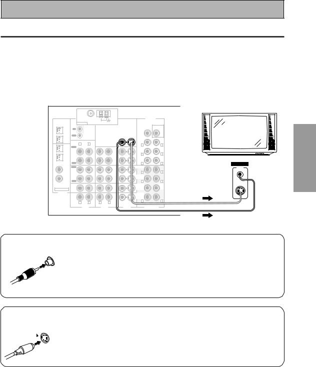
Connect your TV to the jacks as shown below. Hook up with either S video or composite video cords (the quality descends in this order) but you must use the same type of video cords to hook up your DVD player (and all other video components) as you use to hook up your TV. If you plan to hook up your DVD player with S video cords hook up your TV with them as well. Composite video cords, which look just like regular RCA audio cords (see page 19) but have only one cable are the most common.
*The arrows indicate the direction of the signal.
PCM/ |
|
FM UNBAL 75Ω |
|
|
|
|
PRE OUT |
|
|
|
AM LOOP |
|
|
|
|
|
|
2DIGITAL / |
ANTENNA |
|
|
|
|
|
||
DTS/MPEG |
|
|
|
|
|
|
||
|
|
|
|
|
|
SUB |
|
|
|
|
|
|
|
|
|
|
|
OUT1 |
IN |
|
|
|
|
CENTER |
WOOFER |
TV/monitor |
|
|
CONTROL |
|
|
|
|
|
|
|
OUT |
|
|
|
|
|
|
|
OUT2 |
|
|
|
|
|
FRONT |
|
|
|
R |
L |
MONITOR OUT 1 |
|
|
L |
|
|
IN 1 |
|
|
|
R |
|
|||
PLAY |
|
|
|
|
SUR- |
|
|
|
(TV/ |
|
|
|
|
|
|
|
|
SAT) |
IN |
|
|
IN |
|
ROUND |
|
|
|
|
|
|
R |
L |
|
||
IN 2 |
CD-R/ |
|
|
VCR1/ |
|
|
||
(CD-R/ |
TAPE1 |
|
|
DVR |
|
SUR- |
(Single) |
|
TAPE1) |
OUT |
|
|
OUT |
|
ROUND |
|
|
|
|
|
|
BACK |
|
|
||
|
REC |
|
|
|
|
R |
L |
VIDEO IN |
|
|
|
|
|
|
|||
IN 3 |
PLAY |
|
|
|
|
FRONT |
|
VIDEO |
(DVD/ |
IN |
|
|
IN |
|
|
|
|
LD) |
MD/ |
|
|
VCR2 |
|
R |
L |
|
IN 4 |
TAPE2 |
|
|
|
|
SUR- |
|
|
(CD) |
OUT |
|
|
OUT |
|
ROUND |
|
|
REC |
|
|
|
|
R |
L |
|
|
|
|
|
|
|
|
|||
|
CD |
|
|
TV/ |
|
SUB |
CEN- |
S-VIDEO |
|
|
|
|
|
WOOF- |
TER |
|
|
|
IN |
|
|
SAT |
|
|
||
ASSIGNABLE |
|
|
|
ER |
|
|
||
|
|
|
IN |
|
|
|
|
|
DIGITAL |
LINE |
|
|
DVD/ |
|
SUR- |
|
|
|
|
|
|
|
ROUND |
|
|
|
|
|
|
|
LD |
|
|
|
|
|
IN |
|
|
|
BACK |
|
|
|
|
|
|
IN |
|
|
|
||
|
|
|
|
|
R |
L |
|
|
|
R |
L |
R |
L |
|
|
||
|
VIDEO |
S VIDEO |
|
|
||||
|
|
|
|
|
|
|
||
|
|
AUDIO |
AUDIO |
|
VIDEO |
MULTI CH IN |
|
|
Composite Video
Composite video cords are the most common or standard video cord but also the lowest quality. The color on the connector is yellow to distinguish it from regular RCA audio cords which have white and red connectors (see page 19). It is important to use a true composite video cord and not an audio cord (though they look exactly the same) because the impedance is different and this will affect the picture quality.
S Video
S |
|
VIDEO |
S video cables produce clearer picture reproduction by sending separate |
|
|
|
signals for the luminance and the color. |
PREPARATION
15
En
Connecting Your Equipment
Connecting Video Components
Before making or changing the connections, switch off the power and disconnect the power cord from the AC outlet.
Connect your video components as shown on this and the following page. For video components (for example, a DVD player) there are two types of connections to make, video and audio.
Hook up your video signal with either S video or composite video cords (the quality descends in this order) but you must use the same type of cord as you used to hook up your TV.
For the audio signal, in order to use digital soundtracks like Dolby Digital or DTS you must hook up a digital input, with either a coaxial or optical cord (see page 21). It is also a good idea to hook up your components with analog audio connections as well.
If you want to record from your DVD player composite (or S video) cord connections and analog audio connections are necessary.
Connecting a DVD player
Before making or changing the connections, switch off the power and disconnect the power cord from the AC outlet.
Hook up your audio signal with either a coaxial or optical digital cords (you don't need to do both). If you have a DVD-Audio or Super Audio CD (SACD) compatible player, see "Connecting to the Multi Channel Analog Inputs" on page 20.
You need to hook up your audio with analog connections as well.
*The arrows indicate the direction of the signal.
|
FM UNBAL 75Ω |
|
|
|
|
PRE OUT |
|
DIGITAL OUT |
|
PCM/ |
|
|
|
|
|
|
|||
|
|
AM LOOP |
|
|
|
1 |
|
|
|
2DIGITAL / |
ANTENNA |
|
|
|
|
|
|
||
DTS/MPEG |
|
|
|
|
|
|
SUB |
|
(not a PCM-only output) |
OUT1 |
IN |
|
|
|
|
CENTER |
WOOFER |
3 |
|
|
CONTROL |
|
|
|
|
2 |
|
||
|
OUT |
|
|
|
|
|
|
|
|
OUT2 |
|
|
|
|
|
FRONT |
|
|
|
|
R |
L |
MONITOR OUT 1 |
|
|
L |
|
|
|
IN 1 |
|
|
|
R |
|
|
|||
PLAY |
|
|
|
|
|
|
|||
|
|
|
|
SUR- |
|
|
|
||
(TV/ |
|
|
|
|
|
|
|
|
|
SAT) |
IN |
|
|
|
IN |
ROUND |
|
|
|
|
|
|
|
R |
L |
|
|
||
IN 2 |
CD-R/ |
|
|
|
VCR1/ |
VIDEO |
|
||
(CD-R/ |
TAPE1 |
|
|
|
DVR |
SUR- |
(Single) |
|
|
TAPE1) |
OUT |
|
|
|
OUT |
ROUND |
|
VIDEO |
|
|
|
|
|
BACK |
|
|
|||
|
REC |
|
|
|
|
R |
L |
OUT |
DVD player |
(DVD/ |
IN |
|
|
|
IN |
|
|||
|
|
|
FRONT |
|
|
||||
IN 3 |
PLAY |
|
|
|
|
|
|
|
|
LD) |
MD/ |
|
|
|
VCR2 |
R |
L |
|
|
|
|
|
|
|
|
|
|
||
IN 4 |
TAPE2 |
|
|
|
|
SUR- |
|
S-VIDEO |
|
(CD) |
OUT |
|
|
|
OUT |
ROUND |
|
|
|
|
REC |
|
|
|
|
R |
L |
|
|
|
CD |
|
|
|
TV/ |
SUB |
CEN- |
|
|
|
|
|
|
|
WOOF- |
TER |
|
|
|
|
IN |
|
|
|
SAT |
|
|
||
ASSIGNABLE |
|
|
|
ER |
|
|
|
||
|
|
|
|
IN |
|
|
|
|
|
DIGITAL |
LINE |
|
|
|
DVD/ |
SUR- |
|
|
|
|
|
|
|
|
ROUND |
|
|
|
|
|
|
|
|
|
LD |
|
|
|
|
|
IN |
|
|
|
BACK |
|
|
|
|
|
|
|
|
IN |
|
|
|
||
|
|
|
|
|
R |
L |
|
|
|
|
R |
L |
R |
L |
|
|
|
||
|
VIDEO |
S VIDEO |
ANALOG |
|
|||||
|
AUDIO |
|
AUDIO |
|
VIDEO |
MULTI CH IN |
AUDIO |
|
|
|
|
|
|
|
|
|
|
L |
|
R
memo • Be sure to make either a digital coaxial or digital optical connection (pictured as DIGITAL  jack 3 or DIGITAL jack 2 in this diagram) but you DON'T need to make both.
•If your digital connections are different than the default settings you will need to assign the digital jacks to the proper component(s) with the "Assigning the Digital Inputs" procedure. See page 80 to do this.
16
En
Connecting Your Equipment
Connecting VCRs or DVRs
Before making or changing the connections, switch off the power and disconnect the power cord from the AC outlet.
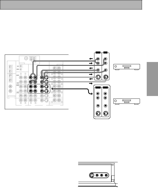
Connect the video out of your VCR/DVR using either S video or composite video cords, depending on how you connected the receiver to your TV (see page 15). Use analog audio cords for the audio signal. To record, you also need to connect a set of audio/video outputs from the receiver to the audio/video inputs on your VCR/DVR. Note that to record video from a source component, the video connection from the source to the receiver and from the receiver to the recorder must be the same type.
*The arrows indicate the direction of the signal.
|
|
|
|
|
|
|
|
OUT |
IN |
|
|
|
|
|
|
|
|
|
AUDIO |
AUDIO |
|
|
|
|
|
|
|
|
|
(PLAY) |
(REC) |
|
|
|
|
|
|
|
|
|
L |
L |
|
PCM/ |
|
FM UNBAL 75Ω |
|
|
|
|
PRE OUT |
|
|
|
|
|
AM LOOP |
|
|
|
|
|
|
|
|
2DIGITAL / |
ANTENNA |
|
|
|
|
|
|
|
||
DTS/MPEG |
|
|
|
|
|
R |
R |
|
||
|
|
|
|
|
|
SUB |
|
|||
|
|
|
|
|
|
|
|
|
|
|
OUT1 |
IN |
|
|
|
|
CENTER |
WOOFER |
|
|
|
|
CONTROL |
|
|
|
|
|
VIDEO |
VIDEO |
|
|
|
|
|
|
|
|
|
|
|||
|
OUT |
|
|
|
|
|
|
|
|
|
OUT2 |
R |
L |
|
|
|
FRONT |
L |
S-VIDEO |
S-VIDEO |
VCR 1/DVR |
|
MONITOR OUT 1 |
|
R |
|||||||
IN 1 |
PLAY |
|
|
|
|
SUR- |
|
|
|
|
(TV/ |
|
|
|
|
|
|
|
|
|
|
SAT) |
IN |
|
|
IN |
|
ROUND |
|
|
|
|
|
|
|
|
R |
L |
|
|
|
||
IN 2 |
CD-R/ |
|
|
VCR1/ |
|
|
|
|
||
(CD-R/ |
TAPE1 |
|
|
DVR |
|
SUR- |
(Single) |
|
|
|
TAPE1) |
OUT |
|
|
OUT |
|
ROUND |
|
|
|
|
|
|
|
|
BACK |
|
|
|
|
||
|
REC |
|
|
|
|
R |
L |
|
|
|
|
|
|
|
|
|
|
|
|
||
IN 3 |
PLAY |
|
|
|
|
FRONT |
|
|
|
|
(DVD/ |
IN |
|
|
IN |
|
R |
L |
OUT |
IN |
|
LD) |
MD/ |
|
|
VCR2 |
|
|
||||
IN 4 |
TAPE2 |
|
|
|
|
SUR- |
|
AUDIO |
AUDIO |
|
(CD) |
OUT |
|
|
OUT |
|
ROUND |
|
(PLAY) |
(REC) |
|
|
|
|
|
|
|
|||||
|
REC |
|
|
|
|
R |
L |
|
|
|
|
CD |
|
|
TV/ |
|
SUB |
CEN- |
L |
L |
|
|
IN |
|
|
SAT |
|
WOOF- |
TER |
|
|
|
ASSIGNABLE |
|
|
|
ER |
|
|
|
|
||
|
|
|
IN |
|
|
|
|
|
|
|
DIGITAL |
LINE |
|
|
DVD/ |
|
SUR- |
|
R |
R |
|
|
|
|
|
|
ROUND |
|
|
|
|
|
|
|
|
|
LD |
|
|
|
|
|
|
|
IN |
|
|
|
BACK |
|
|
|
|
|
|
|
|
IN |
|
|
|
|
|
||
|
|
|
|
|
R |
L |
|
|
|
|
|
R |
L |
R |
L |
|
VIDEO |
VIDEO |
|
||
|
VIDEO |
S VIDEO |
|
|
||||||
|
|
AUDIO |
AUDIO |
|
VIDEO |
MULTI CH IN |
|
|
VCR 2 |
|
|
|
|
|
|
|
|
|
|
|
|
|
|
|
|
|
|
|
|
S-VIDEO |
S-VIDEO |
|
Connecting a Video Component to the Front Panel
Before making or changing the connections, switch off the power and disconnect the power cord from the AC outlet.
Connect a portable DVD player, video game console or any video component to the front panel as show here. Front video connections are accessed via the front panel input selector as VIDEO.
*The arrows indicate the direction of the signal.
PREPARATION
STATION TUNING |
TUNER |
CHARACTER/ |
EON |
SELECT |
EDIT |
SEARCH |
MODE |
MULTI JOG/ENTER |
|
||
S-VIDEO |
VIDEO |
L AUDIO |
R |
|
VIDEO INPUT |
|
|
AUDIO-IN/OUT VIDEO-IN/OUT
Be careful! For portable DVD players you will need a specialized cord (for the audio) that has a mini plug on one end and a regular plug on the other.
17
En
Connecting Your Equipment
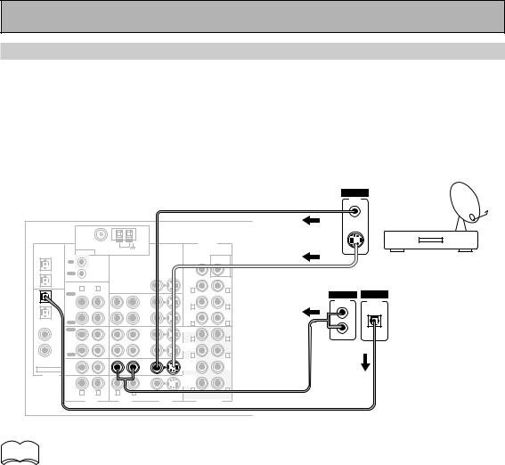
Connecting Satellite TV (SAT) Components
Before making or changing the connections, switch off the power and disconnect the power cord from the AC outlet.
Hook up the video signal with either S video or composite video cords, depending on how you connected the receiver to your TV (see page 15).
For the audio signal, in order to use digital soundtracks broadcast you must hook up a digital input. Use either a coaxial or optical cable, it doesn't matter which (see page 21–22). We recommend hooking up your audio with analog cables as well (see below).
*The arrows indicate the direction of the TV signal.
VIDEO
VIDEO
OUT
|
|
|
|
|
|
|
S-VIDEO |
|
PCM/ |
|
FM UNBAL 75Ω |
|
|
|
|
PRE OUT |
|
|
|
AM LOOP |
|
|
|
|
|
|
2DIGITAL / |
ANTENNA |
|
|
|
|
|
||
DTS/MPEG |
|
|
|
|
|
|
||
|
|
|
|
|
|
SUB |
Satellite tuner |
|
OUT1 |
|
|
|
|
|
|
||
IN |
|
|
|
|
CENTER |
WOOFER |
||
|
|
CONTROL |
|
|
|
|
|
|
|
OUT |
|
|
|
|
|
|
|
OUT2 |
|
|
|
|
|
FRONT |
|
|
|
R |
L |
MONITOR OUT 1 |
|
|
L |
|
|
IN 1 |
|
|
|
R |
|
|||
PLAY |
|
|
|
|
SUR- |
ANALOG |
DIGITAL |
|
(TV/ |
|
|
|
|
|
|
|
|
SAT) |
IN |
|
|
IN |
|
ROUND |
AUDIO |
DIGITAL |
|
|
|
|
|||||
IN 2 |
CD-R/ |
|
|
VCR1/ |
|
R |
L |
|
(CD-R/ |
TAPE1 |
|
|
DVR |
|
SUR- |
(Single) |
|
TAPE1) |
OUT |
|
|
OUT |
|
ROUND |
L |
|
|
|
|
|
BACK |
|
|
||
|
REC |
|
|
|
|
R |
L |
|
|
|
|
|
|
|
|
||
IN 3 |
PLAY |
|
|
|
|
FRONT |
R |
|
(DVD/ |
IN |
|
|
IN |
|
|
|
|
LD) |
MD/ |
|
|
VCR2 |
|
R |
L |
|
IN 4 |
TAPE2 |
|
|
|
|
SUR- |
|
|
(CD) |
OUT |
|
|
OUT |
|
ROUND |
|
|
REC |
|
|
|
|
R |
L |
|
|
|
|
|
|
|
|
|||
|
CD |
|
|
TV/ |
|
SUB |
CEN- |
|
|
|
|
|
|
WOOF- |
TER |
|
|
|
IN |
|
|
SAT |
|
|
||
ASSIGNABLE |
|
|
|
ER |
|
|
||
|
|
|
IN |
|
|
|
|
|
DIGITAL |
LINE |
|
|
DVD/ |
|
SUR- |
|
|
|
|
|
|
|
ROUND |
|
|
|
|
|
|
|
LD |
|
|
|
|
|
IN |
|
|
|
BACK |
|
|
|
|
|
|
IN |
|
|
|
||
|
|
|
|
|
R |
L |
|
|
|
R |
L |
R |
L |
|
|
||
|
VIDEO |
S VIDEO |
|
|
||||
|
|
|
|
|
|
|
||
|
|
AUDIO |
AUDIO |
|
VIDEO |
MULTI CH IN |
|
|
memo • If your digital connections are different than the default settings you will need to assign  the digital jacks to the proper component(s) with the "Assigning the Digital Inputs"
procedure. See page 80 to do this.
18
En
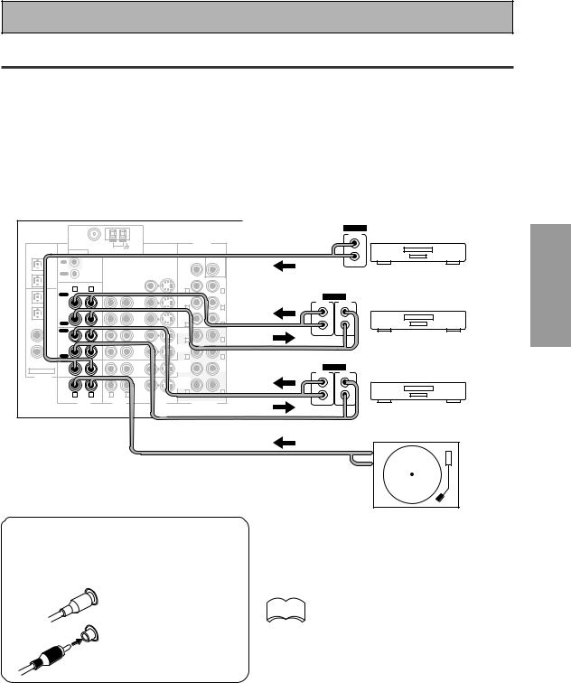
Connecting Your Equipment
Connecting Analog Audio Components
Before making or changing the connections, switch off the power and disconnect the power cord from the AC outlet.
Connect your audio components to the jacks as shown below. These are all analog connections and your analog audio components (turntable, cassette deck) use these jacks. Remember that for components you want to record with you need to hook up four plugs (a set of stereo ins and a set of stereo outs), but for components that only play (like a turntable) you only need to hook up one set of stereo plugs (two plugs). If you want to record to/from digital components (like a CD-R) to/from analog components you must hook up your digital equipment with these analog connections.
*The arrows indicate the direction of the audio signal.
|
|
|
|
|
|
|
|
|
ANALOG |
|
|
|
|
|
|
|
|
|
OUTPUT |
PCM/ |
|
FM UNBAL 75Ω |
|
|
|
|
PRE OUT |
|
L |
2DIGITAL / |
ANTENNA |
AM LOOP |
|
|
|
|
|
|
|
DTS/MPEG |
|
|
|
|
|
|
|
||
|
|
|
|
|
|
SUB |
|
|
|
|
|
|
|
|
|
|
|
R |
|
|
IN |
|
|
|
|
CENTER |
WOOFER |
|
|
OUT1 |
|
|
|
|
|
|
|||
|
CONTROL |
|
|
|
|
|
|
|
|
|
|
|
|
|
|
|
|
CD player |
|
|
OUT |
|
|
|
|
|
|
|
|
OUT2 |
|
|
|
|
|
FRONT |
|
|
|
|
R |
L |
MONITOR OUT 1 |
|
|
L |
|
|
|
IN 1 |
|
|
|
R |
|
|
|||
PLAY |
|
|
|
|
|
|
|||
|
|
|
|
SUR- |
|
ANALOG |
|||
(TV/ |
|
|
|
|
|
|
|||
SAT) |
IN |
|
|
IN |
|
ROUND |
|
OUTPUT |
INPUT |
|
|
|
|
|
|
R |
L |
(PLAY) |
(REC) |
IN 2 |
CD-R/ |
|
|
VCR1/ |
|
|
|
||
|
|
|
|
(Single) |
|
|
|||
(CD-R/ |
TAPE1 |
|
|
DVR |
|
SUR- |
L |
L |
|
TAPE1) |
OUT |
|
|
OUT |
|
ROUND |
|
|
|
|
|
|
|
BACK |
|
|
|
||
|
REC |
|
|
|
|
R |
L |
|
|
|
|
|
|
|
|
R |
R |
||
IN 3 |
PLAY |
|
|
|
|
FRONT |
|
||
|
|
|
|
|
|
|
|||
(DVD/ |
IN |
|
|
IN |
|
SUR- |
L |
|
Recorder 1 (CD-R/TAPE) |
IN 4 |
TAPE2 |
|
|
|
|
|
|||
LD) |
MD/ |
|
|
VCR2 |
|
R |
|
|
|
|
|
|
|
|
|
|
|
||
(CD) |
OUT |
|
|
OUT |
|
ROUND |
|
|
|
|
|
|
|
|
|
|
|||
REC |
|
|
|
|
R |
L |
|
|
|
|
|
|
|
|
|
|
|||
|
CD |
|
|
TV/ |
|
SUB |
CEN- |
|
|
|
IN |
|
|
SAT |
|
WOOF- |
TER |
ANALOG |
|
ASSIGNABLE |
|
|
IN |
|
ER |
|
OUTPUT |
INPUT |
|
DIGITAL |
|
|
|
|
|
|
|
(PLAY) |
(REC) |
LINE |
|
|
DVD/ |
|
SUR- |
|
|
|
|
|
|
|
|
|
|
|
|||
|
|
|
|
|
ROUND |
|
|
|
|
|
IN |
|
|
LD |
|
BACK |
|
L |
L |
|
|
|
IN |
|
|
|
|
||
|
R |
L |
R |
L |
|
R |
L |
|
|
|
VIDEO |
S VIDEO |
|
R |
R |
||||
|
|
|
|
|
|
||||
|
|
AUDIO |
AUDIO |
|
VIDEO |
MULTI CH IN |
|
|
|
|
|
|
|
|
|
|
|
|
Recorder 2 (MD/TAPE) |
PREPARATION
7 Audio cords
Use (RCA) audio cords (not supplied) to connect the audio components.
L |
Connect red plugs to |
|
R (right) and white |
||
|
||
|
plugs to L (left). |
|
R |
Be sure to insert |
|
completely. |
||
|
Turntable (etc)
If you use a turntable with this LINE IN jack only connect one with a built-in phono equalizer.
memo • Depending on where the cassette  deck is placed, noise may occur
during playback of your cassette deck which is caused by leakage flux from the transformer in the receiver. If you experience noise, move the cassette deck farther away from the receiver.
19
En
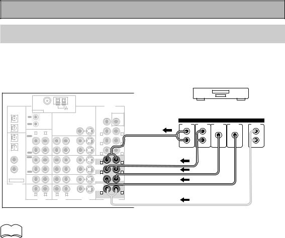
Connecting Your Equipment
Connecting to the Multi Channel Analog Inputs (DVD-Audio or Super
Audio CD (SACD) compatible player)
Before making or changing the connections, switch off the power and disconnect the power cord from the AC outlet.
If you have a DVD-Audio or Super Audio CD (SACD) compatible player, or are using an external Dolby Digital/DTS decoder, connect it to the multichannel analog inputs as shown below.
PCM/ |
|
FM UNBAL 75Ω |
|
|
|
|
PRE OUT |
Components equipped with |
||||
|
|
AM LOOP |
|
|
|
|
5.1 (7.1) channel analog output jack |
|||||
2DIGITAL / |
ANTENNA |
|
|
|
SUB |
|||||||
DTS/MPEG |
|
|
|
|
||||||||
|
|
|
|
|
|
|
|
|
|
|
|
|
OUT1 |
IN |
|
|
|
|
CENTER |
WOOFER |
|
|
|
|
|
|
CONTROL |
|
|
|
|
|
|
|
ANALOG |
|
|
|
|
|
|
|
|
|
|
|
|
|
|
||
|
OUT |
|
|
|
|
|
|
FRONT |
SURR- |
CENTER |
SUB |
SURR- |
OUT2 |
|
|
|
|
|
FRONT |
|
|
OUND |
|
WOOFER |
OUND BACK |
|
|
|
|
|
|
|
|
|
|
|
||
|
R |
L |
MONITOR OUT 1 |
|
R |
L |
|
L |
L |
|
L |
|
IN 1 |
|
|
|
|
|
|||||||
PLAY |
|
|
|
|
|
|
|
|
|
|||
|
|
|
|
SUR- |
|
|
|
|
|
|
||
(TV/ |
|
|
|
|
|
|
|
|
|
|
|
|
SAT) |
IN |
|
|
IN |
|
ROUND |
|
|
R |
R |
|
R |
|
|
|
|
R |
L |
|
|
|||||
IN 2 |
CD-R/ |
|
|
|
|
|
|
|||||
|
|
VCR1/ |
|
|
|
|
|
|
||||
(CD-R/ |
TAPE1 |
|
|
DVR |
|
SUR- |
(Single) |
|
|
|
|
|
TAPE1) |
OUT |
|
|
OUT |
|
ROUND |
|
|
|
|
|
|
|
|
|
BACK |
|
|
|
|
|
|
|||
|
REC |
|
|
|
|
|
|
|
|
|
||
|
|
|
|
|
R |
L |
|
|
|
|
|
|
|
|
|
|
|
|
|
|
|
|
|
||
IN 3 |
PLAY |
|
|
|
|
FRONT |
|
|
|
|
|
|
(DVD/ |
IN |
|
|
IN |
|
|
|
|
|
|
|
|
LD) |
MD/ |
|
|
VCR2 |
|
R |
L |
|
|
|
|
|
IN 4 |
TAPE2 |
|
|
|
|
SUR- |
|
|
|
|
|
|
(CD) |
OUT |
|
|
OUT |
|
ROUND |
|
|
|
|
|
|
REC |
|
|
|
|
R |
L |
|
|
|
|
|
|
|
|
|
|
|
|
|
|
|
|
|||
|
CD |
|
|
TV/ |
|
SUB |
CEN- |
|
|
|
|
|
|
|
|
|
|
WOOF- |
TER |
|
|
|
|
|
|
|
IN |
|
|
SAT |
|
|
|
|
|
|
||
ASSIGNABLE |
|
|
|
ER |
|
|
|
|
|
|
||
|
|
|
IN |
|
|
|
|
|
|
|
|
|
DIGITAL |
LINE |
|
|
DVD/ |
|
SUR- |
|
|
|
|
|
|
|
|
|
|
|
ROUND |
|
|
|
|
|
|
|
|
|
|
|
LD |
|
|
|
|
|
|
|
|
|
IN |
|
|
|
BACK |
|
|
|
|
|
|
|
|
|
|
IN |
|
|
|
|
|
|
|
||
|
|
|
|
|
R |
L |
|
|
|
|
|
|
|
R |
L |
R |
L |
|
|
|
|
|
|
||
|
VIDEO |
S VIDEO |
|
|
|
|
|
|
||||
|
|
|
|
|
|
|
|
|
|
|
||
|
|
AUDIO |
AUDIO |
|
VIDEO |
MULTI CH IN |
|
|
|
|
|
|
memo If you use only one surround back input, be sure to hook up to the SURROUND BACK Ò  jack.
jack.
20
En
Connecting Your Equipment
Connecting Digital Audio Components
Before making or changing the connections, switch off the power and disconnect the power cord from the AC outlet.
Connect your digital components as shown below. The VSX-D1011 has two coaxial, two optical inputs for a total of four digital inputs. In order to use digital soundtracks like Dolby Digital or DTS (among others) you need to make digital audio connections. You can do this by either a coaxial or an optical connection (you don’t need to do both). The quality of these two types of connections is the same but since some digital components only have one type of digital terminal, it is a matter of matching like with like (for example, the coaxial out from the component to coaxial in on the receiver).
Hook up your digital equipment in accordance with this receiver's default settings (see next page) unless you want to, or need to, change them. To do this see "Assigning the Digital Inputs" on page 80.
There are two optical digital out jacks (the CD recorder is connected to one in the diagram below). If you connect this to the optical input on a digital recorder (currently these include MD, DAT and CD-R) you can make direct digital recordings with this unit.
We also recommend hooking up your digital components to analog audio jacks (see page 19) in order to make recordings (some digital sources may be protected against making digital copies).
*The arrows indicate the direction of the audio signal.
PCM/ |
|
FM UNBAL 75Ω |
|
|
|
|
PRE OUT |
|
|
|
|
|
AM LOOP |
|
|
|
|
|
|
|
|
2DIGITAL / |
ANTENNA |
|
|
|
|
|
|
|
||
DTS/MPEG |
|
|
|
|
|
|
|
|
||
|
|
|
|
|
|
SUB |
DIGITAL |
|
||
|
|
|
|
|
|
|
|
|||
OUT1 |
IN |
|
|
|
|
CENTER |
WOOFER |
OUTPUT |
|
|
|
CONTROL |
|
|
|
|
|
|
|||
|
|
|
|
|
|
|
|
|
|
|
|
OUT |
|
|
|
|
|
|
|
|
|
OUT2 |
|
|
|
|
|
FRONT |
|
|
|
|
IN 1 |
PLAY |
L |
MONITOR OUT 1 |
|
|
|
|
|
Satellite tuner |
|
|
R |
|
|
|
R |
L |
|
|
|
|
(TV/ |
|
|
|
|
|
SUR- |
|
DIGITAL |
DIGITAL |
|
SAT) |
IN |
|
|
IN |
|
ROUND |
|
OUTPUT |
INPUT |
|
IN 2 |
CD-R/ |
|
|
VCR1/ |
|
R |
L |
(PLAY) |
(REC) |
|
|
|
|
|
|
|
|||||
|
|
|
|
(Single) |
|
|
|
|||
(CD-R/ |
TAPE1 |
|
|
DVR |
|
SUR- |
|
|
|
|
TAPE1) |
OUT |
|
|
OUT |
|
ROUND |
|
|
|
|
|
|
|
|
BACK |
|
|
|
|
||
|
REC |
|
|
|
|
R |
L |
|
|
|
IN 3 |
PLAY |
|
|
|
|
FRONT |
|
|
|
CD recorder |
(DVD/ |
IN |
|
|
IN |
|
|
|
|
|
|
LD) |
MD/ |
|
|
VCR2 |
|
R |
L |
|
|
|
IN 4 |
TAPE2 |
|
|
|
|
SUR- |
|
|
|
|
(CD) |
OUT |
|
|
OUT |
|
ROUND |
|
|
|
|
|
|
|
|
|
DIGITAL |
|
||||
REC |
|
|
|
|
R |
L |
|
|||
|
|
|
|
|
OUTPUT |
|
||||
|
CD |
|
|
|
|
SUB |
CEN- |
|
||
|
|
|
TV/ |
|
|
|
|
|||
|
IN |
|
|
SAT |
|
WOOF- |
TER |
|
|
|
ASSIGNABLE |
|
|
|
ER |
|
|
|
|
||
|
|
IN |
|
|
|
|
|
|||
|
|
|
|
|
|
|
|
|
||
DIGITAL |
LINE |
|
|
DVD/ |
|
SUR- |
|
|
|
|
|
|
|
|
|
ROUND |
|
|
|
|
|
|
IN |
|
|
LD |
|
BACK |
|
|
|
|
|
|
|
IN |
|
|
|
|
|
||
|
|
|
|
|
R |
L |
|
|
|
|
|
R |
L |
R |
L |
|
|
|
DVD player |
||
|
VIDEO |
S VIDEO |
|
(not a PCM-only output) |
||||||
|
|
|
|
|
|
|
||||
|
|
AUDIO |
AUDIO |
|
VIDEO |
MULTI CH IN |
|
|||
|
|
|
|
|
|
|
|
DIGITAL |
|
|
|
|
|
|
|
|
|
|
OUTPUT |
|
|
PREPARATION
7 Coaxial cords/Optical cables
Commercially available digital audio coaxial cords (standard video cords can also be used) or optical cables (not supplied) are used to connect digital components to this receiver.
Be sure to insert completely and in the case of the optical cable, right-side up. If it is inserted improperly it can break the shutter on the optical terminal (this won't, however, affect the connection or insertion of an optical cable).
CD player
Coaxial cord |
Optical cable |
||
(or standard [composite] |
|
||
video cord) |
|
||
|
|
|
|
21
En
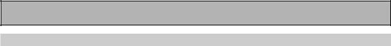
Connecting Your Equipment
Digital Input Default Settings
Unlike analog connections, the jacks for digital connections are not dedicated to one type of component, they can be used freely. Thus you must tell the receiver what digital component is connected to which jack so your components will be in sync with the names on the remote control buttons and the like. To avoid having to assign the digital inputs you can hook up your equipment in accordance with the receiver's default settings.
The default settings are:
DIGITAL IN 1 (optical): TV/SAT
DIGITAL IN 2 (optical): CD-R/TAPE1
DIGITAL IN 3 (coaxial): DVD/LD
DIGITAL IN 4 (coaxial): CD
See "Assigning the Digital Inputs" on page 80 if the way you hook up your equipment is different from the default settings listed here.
22
En
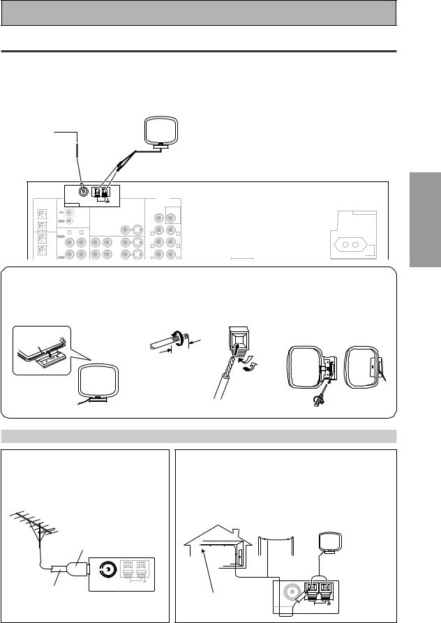
Connecting Your Equipment
Connecting the Radio Antennas
Before making or changing the connections, switch off the power and disconnect the power cord from the AC outlet.
Connect the supplied FM wire antenna and the AM loop antenna to the ANTENNA terminals as shown below. These antennas should provide adequate reception quality in most cases, but connecting outdoor antennas should noticeably improve sound quality.
FM wire |
AM loop |
|
antenna |
||
antenna |
||
|
PCM/ |
|
FM UNBAL 75Ω |
|
|
PRE OUT |
|
|
AM LOOP |
|
|
|
2DIGITAL / |
ANTENNA |
|
|
||
DTS/MPEG |
|
|
|
||
|
|
|
|
SUB |
|
|
|
|
|
|
|
OUT1 |
IN |
|
|
CENTER |
WOOFER |
|
CONTROL |
|
|
|
|
|
|
|
|
|
|
|
OUT |
|
|
|
|
OUT2 |
|
|
|
FRONT |
|
|
R |
L |
MONITOR OUT 1 |
R |
L |
IN 1 |
|
||||
PLAY |
|
|
SUR- |
|
|
(TV/ |
|
|
|
|
|
SAT) |
IN |
|
IN |
ROUND |
|
|
|
R |
L |
||
IN 2 |
CD-R/ |
|
VCR1/ |
||
(CD-R/ |
TAPE1 |
|
DVR |
SUR- |
(Single) |
TAPE1) |
OUT |
|
OUT |
ROUND |
|
|
BACK |
|
|||
|
REC |
|
|
||
|
|
|
R |
L |
|
|
|
|
|
||
7AM loop antenna
1 Assemble the antenna. 2 Twist exposed wire strands
together and insert.
AC OUTLET
SWITCHED 100W MAX
3Attach to a wall, etc. (if desired) and face toward the direction providing the best reception.
10 |
mm |
|
PREPARATION
Using outdoor antennas
7 To improve FM reception
Connect an external FM antenna.
PAL connector
|
|
|
|
|
|
|
|
|
|
|
|
|
|
|
|
|
|
|
F M UNBAL75 Ω |
|
|
||
|
|
|
|
|
|
|
|
|
|
AM LOOP |
|
|
|
|
|
|
|
|
ANTENNA |
|
|
|
|
75 Ω coaxial |
|
|
|
||||||||
cable |
|
|
|||||||||
7 To improve AM reception
Connect a 5 – 6 meter length of vinyl-coated wire to the AM LOOP ANTENNA terminal in addition to the supplied AM loop antenna.
For best possible reception, suspend horizontally outdoors.
Outdoor antenna
AM loop antenna
5–6 m
Indoor antenna
(vinyl-coated wire) |
F M UNBAL75 Ω |
|
ANTENNA |
AM LOOP |
|
|
|
23
En
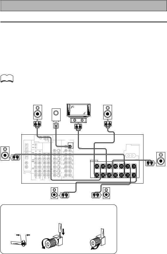
Connecting Your Equipment
Connecting Speakers
Before making or changing the connections, switch off the power and disconnect the power cord from the AC outlet.
We recommend a full complement of seven speakers and a subwoofer as shown here but, naturally, everyone's home setup will vary. Simply connect the speakers you have in the manner described below.
One of the latest features of home theater is the use of surround back speakers. These speakers add even greater realism in movie sound effects and some new discs with soundtracks in Dolby Digital or DTS incorporate these channels. See the page 26 for speaker placement.
In general, make sure you connect the speaker on the right to the R terminal and the speaker on the left to the L terminal. Also make sure the positive and negative (+/–) terminals on the receiver match those on the speakers.
memo |
• We recommend speakers with a nominal impedance rated 8 Ω-16 Ω, but you can change the |
|
speaker impedance setting of the receiver (see page 25). |
||
|
•If you only have one surround back speaker hook it up to the left surround back terminal.
•If you use a THX certified subwoofer use the THX INPUT jack on the subwoofer (if your subwoofer has one) or switch the filter position to THX on your subwoofer.
|
|
|
|
|
Powered |
|
|
|
|
|
|
|
|
|
|
||
|
Front |
|
|
|
subwoofer |
TV/monitor |
|
|
|
|
|
Front |
|
|
|
||
|
|
|
|
|
|
|
|
|
|
|
|
|
|
|
|||
|
speaker |
|
|
|
|
|
|
|
|
|
|
|
|
speaker |
|
|
|
|
(Left) |
|
|
|
|
|
|
|
|
|
|
|
|
(Right) |
|
|
|
|
|
|
|
|
|
|
|
|
Center |
|
|
|
|
|
|
|
|
|
|
|
|
|
|
|
|
|
speaker |
|
|
|
|
|
|
|
|
|
|
|
|
|
|
INPUT |
|
|
|
|
|
|
|
|
|
|
|
Surround |
|
|
FM UNBAL 75Ω |
|
|
|
|
PRE OUT |
|
|
|
|
|
|
|
|
|
speaker |
2DIGITAL / |
|
AM LOOP |
|
|
|
|
|
|
|
|
|
|
|
|
||
ANTENNA |
|
|
|
|
|
|
|
|
|
|
|
|
|
||||
|
PCM/ |
|
|
|
|
|
|
|
|
|
|
|
|
|
|
|
|
(Left) |
DTS/MPEG |
IN |
|
|
|
|
CENTER |
WOOFER |
|
|
|
|
|
|
|
AC OUTLET |
Surround |
OUT1 |
|
|
|
|
|
|
|
|
|
|
|
||||||
|
|
|
|
|
|
|
|
SUB |
|
|
|
|
|
|
|
|
speaker |
|
|
OUT |
CONTROL |
|
|
|
|
|
|
|
|
|
|
|
|
|
|
|
OUT2 |
|
|
MONITOR OUT 1 |
|
FRONT |
|
|
|
|
|
|
|
|
|
(Right) |
|
|
IN 1 |
R |
L |
|
|
|
R |
L |
|
|
|
|
|
|
|
|
|
|
PLAY |
|
|
|
|
SUR- |
|
|
|
|
|
|
|
|
|
|
|
|
(TV/ |
|
|
|
|
|
|
|
|
|
|
|
|
|
|
|
|
|
SAT) |
IN |
|
|
IN |
|
ROUND |
|
|
|
|
|
|
|
|
|
|
|
IN 2 |
CD-R/ |
|
|
VCR1/ |
|
R |
L |
|
|
|
|
|
|
|
|
|
|
(CD-R/ |
TAPE1 |
|
|
DVR |
|
SUR- |
(Single) |
|
|
|
|
|
|
|
|
|
|
TAPE1) |
OUT |
|
|
OUT |
|
ROUND |
|
|
|
|
|
|
|
SWITCHED 100W MAX |
|
|
|
|
|
|
|
BACK |
|
|
|
|
|
|
|
|
||||
|
|
REC |
|
|
|
|
R |
L |
SPEAKERS |
|
|
|
|
|
|
|
|
|
|
|
|
|
|
|
|
|
|
|
|
|
|
||||
|
IN 3 |
PLAY |
|
|
|
|
FRONT |
|
|
|
|
|
SURROUND BACK / ı |
|
|||
|
|
|
|
|
|
Å |
|
FRONT |
|
CENTER |
R SURROUND L |
|
|||||
|
(DVD/ |
IN |
|
|
IN |
|
R |
L |
R |
L |
R |
L |
|
||||
|
LD) |
MD/ |
|
|
VCR2 |
|
|
|
|
|
|
|
|
|
|
||
|
IN 4 |
TAPE2 |
|
|
|
|
SUR- |
|
ª |
|
|
|
|
|
|
ª |
|
|
OUT |
|
|
OUT |
|
ROUND |
|
|
|
|
|
|
|
|
|||
|
(CD) |
|
|
|
|
|
|
|
|
|
|
|
|
|
|
||
|
REC |
|
|
|
|
R |
L |
|
|
|
|
|
|
|
|
|
|
|
|
|
|
|
|
|
|
|
|
|
|
|
|
|
|||
|
|
CD |
|
|
TV/ |
|
SUB |
CEN- |
|
|
|
|
|
|
|
|
|
|
|
IN |
|
|
SAT |
|
WOOF- |
TER |
|
|
|
|
|
|
|
|
|
|
ASSIGNABLE |
|
|
IN |
|
ER |
|
|
|
|
|
|
|
|
|
|
|
|
DIGITAL |
LINE |
|
|
DVD/ |
|
SUR- |
|
|
|
|
|
|
|
|
|
|
|
|
|
|
|
|
ROUND |
|
· |
|
|
|
|
|
|
· |
|
|
|
|
IN |
|
|
LD |
|
BACK |
|
|
|
|
|
|
|
|
||
|
|
|
|
IN |
|
R |
L |
|
|
|
|
|
|
|
|
|
|
|
|
R |
L |
R |
L |
|
|
|
|
|
|
|
|
|
|
||
|
|
VIDEO |
S VIDEO |
|
|
|
|
|
|
|
|
|
|
||||
|
|
|
|
|
|
|
|
|
|
|
|
|
|
|
|
||
|
|
|
AUDIO |
AUDIO |
|
VIDEO |
MULTI CH IN |
|
|
|
|
|
|
|
|
|
|
Surround back |
Surround back |
speaker (Left) |
speaker (Right) |
7 Speaker terminals
1 Twist exposed wire |
2 Loosen speaker terminal |
3 Tighten |
strands tightly |
and insert exposed wire. |
terminal. |
together. |
|
|
10mm
24
En

Connecting Your Equipment
Speaker impedance
You can change the speaker impedance for VSX-D1011 but we recommend using speakers with an impedance of 8 Ω-16 Ω (the default setting). If you are using 6 Ω- less than 8 Ω impedance speakers, you need to change the impedance setting. Use any speaker rated between 6 Ω-16 Ω.
 STANDBY/ON
SPEAKERS
|
|
AUDIO/VID |
STANDBY/ON |
|
|
|
|
STANDBY |
MOVIE |
MUSIC |
ENTER |
MULTI JOG
First put the receiver in STANDBY mode, then press the power button while holding down the
SPEAKERS button.
The receiver will reset to the new impedance
setting. With this method you can choose the 8 Ω- 16 Ω setting or the 6 Ω-8 Ω setting.
To check which impedance setting to hold down the SPEAKERS button for 2-3 seconds. You'll get a display like these telling you the speaker impedance setting.
SIGNAL
ANALOG
SB CH
ON MOVIE AUTO OFF MUSIC
SP A B
SIGNAL
ANALOG
SB CH
ON MOVIE AUTO OFF MUSIC
SP A B
dB
dB
(This display indicates an 8Ω-16Ω impedance setting.)
(This display indicates a 6Ωless than 8Ω impedance setting.)
PREPARATION
25
En
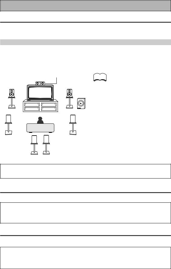
Connecting Your Equipment
Placing Your Speakers
Proper speaker placement is essential to realize the best sound from your system. The diagram and tips given here are just a rough guide, for more information see pages 94 & 95. Also, it is very important for speaker placement to read the instructions that come with your speakers so please be sure to do so.
Speaker placement
If you have a multiple speaker arrangement the placement of the speakers is extremely important. To achieve the best possible surround sound, install your speakers as shown below. Make sure all speakers are installed securely to prevent accidents and improve sound quality. Some speakers are designed to be floor-standing but others benefit greatly from speaker stands which raise them off the floor. Be sure to read your speaker manuals for the best placement of the speakers.
|
Center Speaker |
memo |
Front Speaker |
Front Speaker |
|
(L) |
(R) |
|
Subwoofer
Surround |
Surround |
Speaker (L) |
Speaker (R) |
Surround Back |
Surround Back |
Speaker (L) |
Speaker (R) |
•When installing speakers near the TV, we recommend using magnetically shielded speakers to prevent distortion in the color of the TV screen. If you do not have magnetically shielded speakers and notice discoloration of the TV screen, place the speakers farther away from the TV.
•Install the center speaker above or below the TV so that the sound of the center channel is localized at the TV screen.
•THX recommends that if you have two surround back speakers place them close together.
CAUTION:
When installing the center speaker on top of the TV, be sure to secure it with suitable means.
AC Power Cord
Plug in the power cord to a wall outlet after you have finished hooking up the rest of your equipment.
CAUTION!
•Do not use any other power cord than the one supplied with this unit. (multi-voltage model only)
•The equipment should be disconnected by removing the mains plug from the wall socket when not in regular use, e.g. when on vacation.
AC Outlet [switched 100 W max] (European model only)
Power supplied through this outlet is turned on and off by this unit’s STANDBY/ON button. Total electrical power consumption of connected equipment should not exceed 100 W.
CAUTION!
•Do not connect appliances with high power consumption such as heaters, irons, or television sets to the AC OUTLET in order to avoid overheating or fire risk. This can cause the unit to malfunction.
•DO NOT CONNECT A MONITOR OR TV SET TO THIS UNIT’S AC OUTLET.
26
En
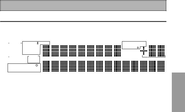
Displays & Controls
Display
All the display information is explained and/or referenced here.
1 |
|
|
|
|
|
|
|
|
|
2 |
|
|
3 |
4 |
5 |
6 |
7 |
|
|||||||||||
|
|
|
|
|
|
|
|
|
|
|
|
|
|
|
|
|
|
|
|
|
|
|
|
|
|
|
|
|
|
|
|
|
SIGNAL |
|
|
PRO LOGIC Neo :6 |
LOUDNESS |
MIDNIGHT |
TONE |
DNR |
|
STEREO MONO |
dB |
||||||||||||||||
|
|
|
|
||||||||||||||||||||||||||
|
|
|
AUTO |
|
|
|
|
|
DIGITAL |
|
|
|
|
|
|
|
|
|
TUNED RF ATT |
|
|||||||||
|
|
|
|
RF |
|
|
|
DTS ES EX |
|
|
|
|
|
|
|
|
RDS EON |
|
|||||||||||
|
|
|
|
|
|
|
|
|
|
|
|
|
|
|
|
||||||||||||||
|
|
|
DIGITAL |
|
|
|
|
|
|
|
|
|
|
|
|
|
|
|
|
|
|
Hi-BIT/ |
|
||||||
|
|
|
|
|
STEREO |
|
|
|
|
|
|
|
|
|
SAMPLING |
|
|||||||||||||
|
|
|
ANALOG |
|
|
|
|
|
|
|
|
|
|
|
|
||||||||||||||
|
|
|
|
|
|
|
|
|
|
|
|
|
DSP |
|
|
|
|
|
|
|
|
|
|
|
|
||||
|
|
|
|
|
|
|
|
|
|
|
|
|
|
|
|
|
|
|
|
|
|
|
|
|
|||||
|
|
|
SB CH |
ON |
|
|
MOVIE |
|
|
|
|
|
|
|
|
|
|
|
|
|
|
||||||||
|
|
|
AUTO |
|
|
|
|
|
|
|
|
|
|
|
|
|
|
|
|||||||||||
|
|
|
|
|
|
OFF |
|
|
MUSIC |
|
|
|
|
|
|
|
|
|
|
|
|
|
|||||||
|
|
|
|
|
|
|
|
|
|
|
|
|
|
|
|
|
|
|
|
|
|
|
|
|
|
|
|
|
|
|
|
|
|
|
|
|
|
|
|
|
|
|
|
|
|
|
|
|
|
|
|
|
|
|
|
|
|
|
|
|
|
|
|
|
|
|
|
|
|
|
|
LFE |
|
|
|
|
|
|
|
|
|
|
|
|
|||||
|
|
|
|
|
|
|
|
|
|
|
|
SP A B |
|
|
|
|
|
|
|
|
|
|
|
|
|
||||
|
|
|
|
|
|
|
|
|
|
|
|
|
|
|
|
|
|
|
|
|
|
|
|
|
|||||
|
|
|
|
|
|
|
|
|
|
|
|
|
|
|
|
|
|
|
|
|
|
|
|
|
|
|
|
|
|
|
|
|
|
|
|
|
|
|
|
|
|
|
|
|
|
|
|
|
|
|
|
|
|
|
|
|
|
|
|
|
|
|
|
|
|
|
|
|
|
|
|
|
|
|
|
|
|
|
|
|
|
|
|
|
|
|
|
|
|
12 11 10
1SIGNAL SELECT indicators
Light to indicate the input signal you selected.
AUTO: Lights when the receiver is set to select the input signal automatically.
DIGITAL: Lights when digital audio signals are selected.
ANALOG: Lights when analog signals are selected.
2 Digital format indicators
PRO LOGIC II: Lights during Dolby Pro Logic II processing.
NEO:6: Lights during NEO:6 processing.
2DIGITAL: Lights when a Dolby Digital signal is detected.
DTS: Lights when a DTS signal is detected. ES: Lights when playing back a DTS ES signal.
EX: Lights when playing back a Dolby Digital EX signal.
STEREO: Lights during two-channel playback.
3LOUDNESS indicator
Lights when LOUDNESS is on.
4MIDNIGHT indicator
Lights when MIDNIGHT is on.
5TONE indicator
Lights when the TONE control is on.
6DNR indicator
Lights when DIGITAL NR is on.
7TUNER indicators
STEREO: Lights when an FM stereo broadcast is received in the auto stereo mode.
MONO: Lights when the tuner is set to receive FM broadcasts and when MPX mode is selected.
TUNED: Lights when a broadcast is received.
RF ATT (European model only): Lights when the RF ATT is on (see page 54).
RDS (European model only): Lights when an RDS broadcast is received.
9 |
8 |
EON o (European model only): EON lights when it has been set. The dot indicator next to it lights when the station you are currently tuned to carries the EON data service.
8Volume level indicator
9Hi-BIT/SAMPLING indicator
Lights when a HI-BIT/SAMPLING mode is on.
10DSP indicators
MOVIE: Lights when a MOVIE mode is selected. When a DSP MOVIE mode is selected DSP will light with a box around it.
MUSIC: Lights when a MUSIC mode is selected. When a DSP MUSIC mode is selected DSP will light with a box around it.
11Program Format indicators
For Dolby Digital or DTS sources: These indicators change according to which channels are active in the source. When all three LS (left surround), S (surround) and RS (right surround) light at the same time it means a source with a 6.1 channel playback flag is being used.
L – Left front channel. C – Center channel.
R – Right front channel.
LS – Left surround channel.
S – Surround channel or Surround back channel. RS – Right surround channel.
LFE – Low Frequency Effects channel.
‡ – Lights when LFE signal is input.
12SB CH indicators
Light to indicate the status of the surround back channels.
AUTO – Lights when the SB CH MODE or VIRTUAL SURROUND BACK mode is set to AUTO.
ON – Lights when the SB CH MODE or VIRTUAL SURROUND BACK mode is set to ON.
OFF – Lights when the SB CH MODE or VIRTUAL SURROUND BACK mode is set to OFF.
PREPARATION
27
En

Displays & Controls
Front Panel
All the controls on the front panel are explained and/or referenced here. To open the front panel push gently on the lower third of the panel.
|
2 |
|
|
|
|
|
9 |
10 |
11 |
1 |
3 |
4 |
5 |
6 |
7 |
8 |
|||
|
|
|
|
|
|
|
AUDIO/VIDEO MULTI-CHANNEL RECEIVER VSX-D1011 |
|
|
|
STANDBY/ON |
|
|
|
|
|
|
|
|
|
|
|
|
STANDBY |
|
|
|
|
|
MOVIE |
MUSIC |
ENTER |
STEREO/DIRECT MULTI CH IN |
ACOUSTIC EQ |
MULTI JOG |
MASTER VOLUME |
MULTI JOG |
CONTROL |
SIGNAL |
HI-BIT |
SB CH |
BAND |
CLASS |
STATION TUNING |
TUNER |
CHARACTER/ |
EON |
|
SET UP |
RETURN |
SELECT |
HI-SAMPLING |
MODE |
SELECT |
EDIT |
SEARCH |
MODE |
|||
|
|
|
TONE CONTROL |
|
|
|
MULTI JOG/ENTER |
|
|
||
PHONES |
|
|
|
|
|
|
|
|
|
||
|
SPEAKERS |
TONE |
BASS/TREBLE |
|
|
|
|
|
|
|
|
|
|
|
|
|
|
|
S-VIDEO |
VIDEO |
L |
AUDIO |
R |
|
|
|
|
|
|
|
|
VIDEO INPUT |
|
|
|
|
|
|
|
|
|
|
|
|
|
|
|
|
|
|
|
|
|
|
|
|
|
|
|
|
|
|
|
|
|
|
|
|
|
|
|
|
|
|
|
|
|
|
|
|
12 |
13 |
14 |
15 |
16 |
17 |
18 |
|
|
|
|||||
MULTI JOG |
CONTROL |
SIGNAL |
HI-BIT |
SB CH |
|
|
STATION TUNING |
TUNER |
CHARACTER/ |
EON |
SET UP |
RETURN |
SELECT |
HI-SAMPLING |
MODE |
BAND |
CLASS |
SELECT |
EDIT |
SEARCH |
MODE |
|
|
|
TONE CONTROL |
|
|
MULTI JOG/ENTER |
|
|||
PHONES |
|
|
|
|
|
|
|
|
||
|
SPEAKERS |
TONE |
BASS/TREBLE |
|
|
|
|
|
|
|
|
|
|
|
|
|
|
S-VIDEO |
VIDEO |
L AUDIO |
R |
|
|
|
|
|
|
|
|
VIDEO INPUT |
|
|
European model
19 |
20 |
21 |
22 |
12 13 14 15 23 24 16
MULTI JOG |
CONTROL |
SIGNAL |
HI-BIT |
SB CH |
MIDNIGHT LOUDNESS |
BAND |
CLASS |
|
STATION TUNING |
|
TUNER |
SET UP |
RETURN |
SELECT |
HI-SAMPLING |
MODE |
SELECT |
|
|
EDIT |
|||
PHONES |
|
|
TONE CONTROL |
|
|
|
|
|
|
MULTI JOG/ENTER |
|
|
|
|
|
|
|
|
|
|
|||
|
SPEAKERS |
TONE |
BASS/TREBLE |
|
|
|
|
|
|
|
|
|
|
|
|
|
|
|
|
S-VIDEO |
VIDEO |
L |
AUDIO R |
|
|
|
|
|
|
|
|
|
VIDEO INPUT |
|
|
multi-voltage model
19 |
20 |
21 |
1MULTI JOG dial
You can use this dial for many purposes. When you press the SET UP button (12), you can use it to perform SYSTEM SETUP operations; select a function (like a DVD) or a listening mode (like Dolby Pro logic ll) or do TUNER EDIT functions (in TUNER mode).
2Listening mode buttons (see pages 4345)
There are two types of SURROUND modes:
MOVIE: Press to put the receiver into MOVIE listening mode (see page 44).
28 |
MUSIC: Press to put the receiver into MUSIC |
En |
listening mode (see page 45). |
22
STEREO/DIRECT (see page 43): Switches the receiver into STEREO mode if it was in a different sound mode or toggles between DIRECT and STEREO mode.
DIRECT playback bypasses the tone controls and channel level for the most accurate reproduction of a program source.
3–OFF -ON button
Press to switch the receiver between OFF and STANDBY mode or ON.
 STANDBY/ON button
Press to switch the receiver between ON and STANDBY mode.

Displays & Controls
4ENTER button
Use this button to enter information concerning the SYSTEM SETUP, listening mode or the tuner.
5STANDBY indicator
Lights when the receiver is in STANDBY mode. (Please note that this receiver consumes a small amount of power [0.7 W for the European model and 0.9 W for the multi-voltage model] in the standby mode.)
6Remote sensor
Receives the signals from the remote control.
7Display (See page 27)
8MCACC indicator (see page 47)
Lights when the ACOUSTIC CAL EQ is on.
9MULTI CH IN button
Use this button to select the component you have hooked up to the MULTI CH IN terminals (for example, a DVD-Audio player).
10ACOUSTIC EQ button (see page 47)
Use to switch on and off the Acoustic Calibration EQ.
11MASTER VOLUME dial
Use to raise or lower the volume of the receiver.
12MULTI JOG CONTROL buttons
SET UP
Press to switch the SYSTEM SETUP mode.
RETURN
Press to move back one step in the SYSTEM SETUP process.
13SIGNAL SELECT button (see page 42)
Press SIGNAL SELECT repeatedly to select one of the following:
AUTO – If there are analog and digital signals input, the receiver automatically selects the digital signal.
DIGITAL – To select an optical or coaxial digital signal.
ANALOG – To select an analog signal.
14 HI-BIT HI-SAMPLING button (see page 50)
Use this button to switch the HI-BIT HI-SAMPLING on or off. Use to hear CD and DVD, as well as other digital soundtracks at a wider dynamic range, allowing for finer audio reproduction.
15 SB CH MODE button (see page 51)
Use this button to turn the surround back channels ON/OFF/AUTO or switch the VIRTUAL SURROUND BACK mode between ON/ OFF/AUTO.
16 TUNER CONTROL buttons (See page
54-62)
BAND
Press to select the AM or FM band.
CLASS
Press repeatedly to switch the preset station classes.
SELECT
Switches the –/+ buttons between station memory and frequency select modes.
–/+
Selects station memories or frequencies when using the tuner.
TUNER EDIT
Press to memorize and name a station for recall using the MULTI JOG and ENTER buttons.
17 CHARACTER/SEARCH button (See page
60)
Use to search for different program types in RDS mode.
18 EON MODE button (see pages 61-62)
Use to search for different programs that are transmitting traffic or news information (this search method is called EON).
19 PHONES jack
Connect headphones for private listening (no sound will be heard through the speakers).
20 SPEAKERS (A/B) button
The use of this button depends on how the SURRBACK SYSTEM (see page 35) are set. If NORMAL SYSTEM is chosen this button toggles between A and OFF. If SECOND ZONE is chosen this button toggles between A, B, A+B and OFF (see page 70). If FRONT BI-AMP is chosen this button toggles between A+B and OFF (see page 70).
21 TONE CONTROL buttons (see page 49)
TONE button
This button switches between TONE ON and TONE BYPASS, which bypasses the tone circuitry.
BASS/TREBLE button
Use to select whether the bass or treble will be adjusted.
–/+ buttons
Use to adjust the frequency levels.
22 VIDEO INPUT jacks (see page 17)
S-VIDEO
Video input for connecting a portable DVD player, video camera (etc.), that has an S video out.
RCA VIDEO / AUDIO (L/R)
Video input for connecting a portable DVD player, video camera, etc., that has standard RCA video/audio outputs.
23 MIDNIGHT button (see page 48)
Switches the MIDNIGHT listening mode on or off (for all modes except THX CINEMA and MULTI CH IN).
24 LOUDNESS button (see page 48)
Switches the LOUDNESS mode on or off (for all modes except THX CINEMA and MULTI CH IN).
PREPARATION
29
En
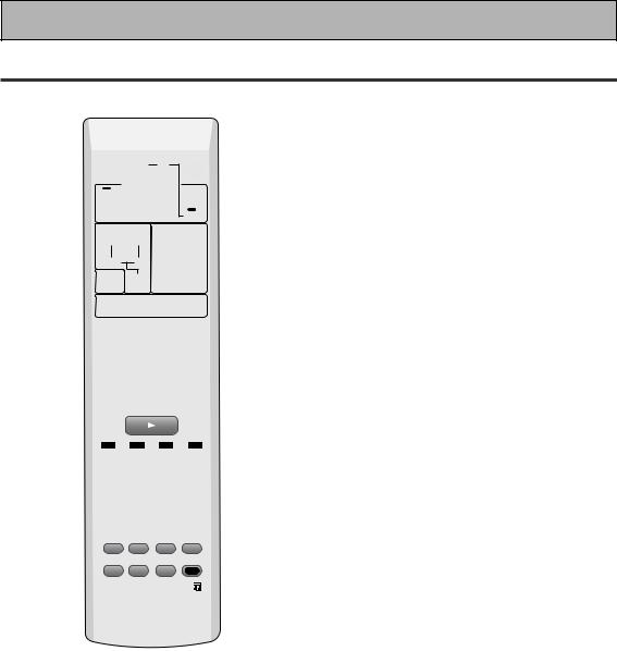
Displays & Controls
Remote Control
This page describes the buttons on the remote control used to operate the receiver.
1
2
3
RECEIVER MULTI |
SYSTEM |
OPERATION |
OFF |
MULTI CONTROL
DVD/LD TV/SAT VCR1/DVR
VCR 2 |
C D |
TUNER |
MOVIE |
MUSIC |
ACOUSTIC |
EQ |
||
SURROUND |
SB CH |
|
MODE |
MODE |
|
STEREO/ |
ENTER |
MIDNIGHT |
DIRECT |
||
SOURCE
TV CONT
RECEIVER |
INPUT
MULTI CH
INPUT
MUTE
9
0
-
=
~
MASTER |
|
|
VOLUME |
! |
|
MENU TUNER EDIT |
TEXT ON TOP MENU |
|
4 |
TUNE |
@ |
SYSTEM |
GUIDE |
|
SETUP |
|
|
ST |
ST |
# |
|
ENTER |
|
AUDIO |
|
RETURN |
5 |
TUNE |
$ |
|
CHANNEL− |
TEXT OFF |
BAND |
CHANNEL+ |
|
6 |
RF ATT |
D.ACCESS |
MPX |
|
CLASS |
|
DIMMER |
LOUDNESS |
TONE |
EFFECT/CH SEL |
|
|
|
|
|
ENTER |
|
7 |
SIGNAL SEL |
DNR |
BASS/TREBLE |
|
DISC |
|
|
|
+ |
|
|
|
VIDEO SEL |
HI-BIT |
|
+10 |
|
|
|
− |
|||
8 |
TV CONTROL |
SUB TITLE |
% |
||
INPUT |
CHANNEL |
VOLUME |
REMOTE |
||
|
|||||
SELECT |
|
||||
|
|
|
SETUP |
^ |
|
|
|
|
|
||
RECEIVER
1  RECEIVER (STANDBY/ON) button
Press to turn power of the receiver on or to standby (off).
2MULTI CONTROL buttons
These buttons are the basic controls that switch the mode of the receiver and the remote control, which allows you to control your other components.
TV CONT: Press so that the remote control can operate the TV control commands.
3Listening mode buttons (see page 4345)
SURROUND buttons (MOVIE, MUSIC, | \
& ENTER):
MOVIE: Press to put the receiver into MOVIE listening mode (see page 44).
MUSIC: Press to put the receiver into MUSIC listening mode (see page 45).
30 |
| \: Use to select the MOVIE or MUSIC |
En |
listening mode. |
ENTER: Use this button to enter information concerning the listening modes.
STEREO/DIRECT: Switches the receiver into STEREO mode if it was in a different sound mode or toggles between DIRECT and STEREO mode (see page 43).
4SYSTEM SETUP button
Use for all system setups, including the speaker and sound systems. For more information see. “Setting up for Surround Sound“ starting on page 34. For a DVD player use this button to bring up the DVD menu and for a tuner use this button in the same way as the TUNER EDIT button.
5AUDIO button
Use to switch the audio tracks of a DVD when in DVD mode.
6Command button for other components (see pages 65–66)
Use these buttons to control other components you selected with the MULTI CONTROL buttons. You must input the preset code in order use this function (see page 63).
7Number buttons
These can be used for many purposes depending on the mode of the remote control.
When in receiver mode the buttons operate as below:
DIMMER button (see page 53)
Use to adjust the brightness of the receiver's display.
LOUDNESS button (see page 48)
Switches the LOUDNESS mode on or off (for all modes except THX CINEMA and MULTI CH IN).
TONE button (see page 49)
This button switches between TONE ON and TONE BYPASS, which bypasses the tone circuitry.
SIGNAL SELECT button (see page 42)
Press SIGNAL SELECT repeatedly to select one of the following:
AUTO – If there are analog and digital signals input, the receiver automatically selects the digital signal.
DIGITAL – To select an optical or coaxial digital signal.
ANALOG – To select an analog signal.
 Loading...