


VSX-909RDS

Operating Instructions
AUDIO/VIDEO
MULTI-CHANNEL RECEIVER
VSX-909RDS
VSX-909RDS-G

2
En
Thank you for buying this Pioneer product.
Please read through these operating instructions
so you will know how to operate your model prop-
erly. After you have finished reading the instruc-
tions, put them away in a safe place for future ref-
erence.
In some countries or regions, the shape of the
power plug and power outlet may sometimes dif-
fer from that shown in the explanatory drawings.
However, the method of connecting and operat-
ing the unit is the same.
Power cord CAUTION
Handle the power cord by the plug. Do not pull
out the plug by tugging the cord and never
touch the power cord when your hands are
wet as this could cause a short circuit or
electric shock. Do not place the unit, a piece of
furniture, etc., on the power cord, or pinch the
cord. Never make a knot in the cord or tie it
with other cords. The power cords should be
routed such that they are not likely to be
stepped on. A damaged power cord can cause
a fire or give you an electrical shock. Check the
power cord once in a while. When you find it
damaged, ask your nearest PIONEER
authorized service center or your dealer for a
replacement.
WARNING: TO PREVENT FIRE OR SHOCK
HAZARD, DO NOT EXPOSE THIS APPLIANCE TO
RAIN OR MOISTURE.
THE ON/OFF BUTTON IS SECONDARY CONNECTED
AND THEREFORE DOES NOT SEPARATE THE UNIT
FROM MAINS POWER IN STANDBY POSITION.
[For European model]
If the socket outlets on the associated equipment
are not suitable for the plug supplied with the
product the plug must be removed and
appropriate one fitted.
The cut-off plug must be disposed of as an
electrical shock hazard could exist if connected to
a socket outlet.
Maintenance of External Surfaces
• Use a polishing cloth or dry cloth to wipe off dust and dirt.
• When the surfaces are dirty, wipe with a soft cloth dipped in some neutral cleanser diluted five or six times
with water, and wrung out well, and then wipe again with a dry cloth. Do not use furniture wax or cleansers.
• Never use thinners, benzine, insecticide sprays or other chemicals on or near this unit, since these will corrode
the surfaces.
RISK OF ELECTRIC SHOCK
DO NOT OPEN
CAUTION
IMPORTANT
CAUTION:
TO PREVENT THE RISK OF ELECTRIC SHOCK, DO
NOT REMOVE COVER (OR BACK). NO USER-
SERVICEABLE PARTS INSIDE. REFER SERVICING TO
QUALIFIED SERVICE PERSONNEL.
The exclamation point within an equilateral triangle is
intended to alert the user to the presence of important
operating and maintenance (servicing) instructions in
the literature accompanying the appliance.
The lightning flash with arrowhead symbol, within an
equilateral triangle, is intended to alert the user to the
presence of uninsulated "dangerous voltage" within the
product's enclosure that may be of sufficient magnitude
to constitute a risk of electric shock to persons.
IMPORTANT
Do not connect either wire to the earth terminal of a
three - pin plug.
NOTE
After replacing or changing a fuse, the fuse cover in the
plug must be replaced with a fuse cover which corre-
sponds to the colour of the insert in the base of the plug
or the word that is embossed on the base of the plug, and
the appliance must not be used without a fuse cover. If
lost replacement fuse covers can be obtained from:
your dealer.
Only 5 A fuses approved by B.S.I. or A.S.T.A. to B.S.
1362 should be used.
The cut-off plug should be disposed of and must not be
inserted into any 13 amp socket as this can result in electric
shock. The plug or adaptor or the distribution panel should
be provided with 5 amp fuse. As the colours of the wires in
the mains lead of this appliance may not correspond with
coloured markings identifying the terminals in your plug,
proceed as follows :
The wire which is coloured blue must be connected to the
terminal which is marked with the letter N or coloured black.
The wire which is coloured brown must be connected
to the terminal which is marked with the letter L or coloured
red.
FOR USE IN THE UNITED
KINGDOM
The wires in this mains lead are coloured in
accordance with the following code :
Blue : Neutral
Brown : Live
If the plug provided is unsuitable for your socket
outlets, the plug must be cut off and a suitable plug
fitted.
This product complies with the Low Voltage
Directive (73/23/EEC), EMC Directives (89/336/
EEC, 92/31/EEC) and CE Marking Directive (93/
68/EEC).
III
En
Quick Start Guide
Before making or changing the connections, switch off the power and disconnect the power cord from
the AC outlet.
This is a quick guide to setting up your new receiver so you can get home theater surround sound. For more
details on any of the information presented here check the main section of the manual.
11
11
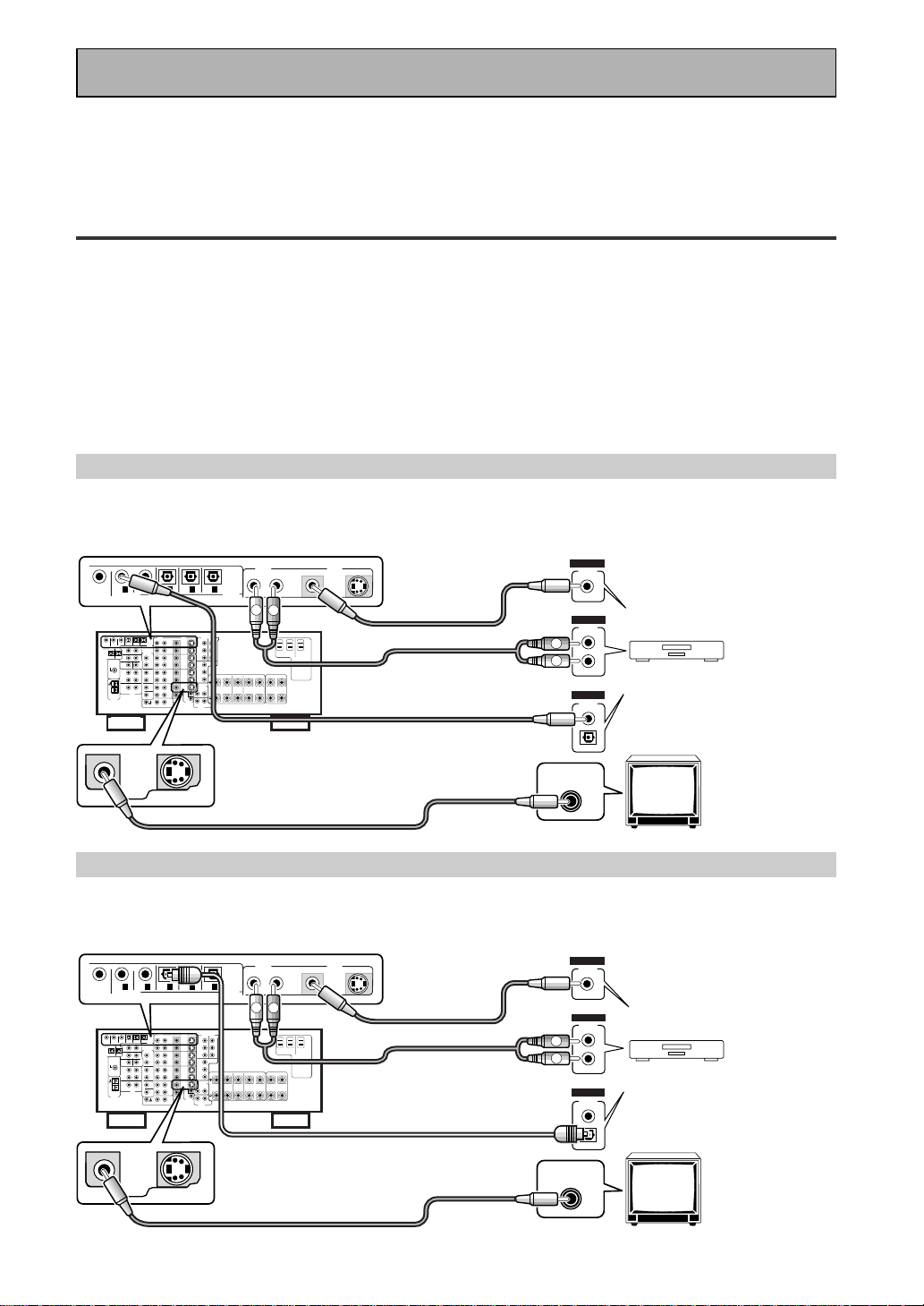
1 Hooking Up Your DVD Player & TV
In order to use Dolby Digital/DTS soundtracks which are at the heart of home theater you need to hook up your
DVD player with digital audio connections. You can do this by either a coaxial or an optical connection, you don’t
need to do both. The quality of these two types of connections is the same but since some digital components
only have one type of digital terminal you need to figure out which yours has and hook it up to the appropriate
terminal on the receiver. In order to do this you will need the proper cable. For coaxial connections you can use a
regular RCA stereo cord or the specially-made coaxial cords, they have the same type of plugs. For optical
connections you will need a special optical cord which you can buy at your local stereo store. Also hook up the
video connection of your DVD player, the analog audio (for recording the audio on DVDs, use regular RCA stereo
cords), and your TV (it's easiest to use a regular composite RCA video cords) as shown below. It is important
that you hook up your TV (or monitor) in order to see a video image as well as the on screen displays (OSDs)
shown by this receiver (for more on p.16-17). We also recommend hooking up your all your digital components
to analog audio jacks. For this you can use regular RCA stereo cords.
Coaxial Digital Connection
If your DVD player has a coaxial terminal (not a PCM-only output) for the audio out hook it up using this terminal.
Follow the diagram below. This is the best scenario, as you will be able to follow the default settings of this
receiver and won't need to assign the digital inputs.
Optical Digital Connection
If your DVD player has an optical terminal (not a PCM-only output) for the audio out you can hook it up using this
following the diagram below. You will need to assign the digital input (tell the receiver which input you put your
DVD digital audio into). See page VI for this.
(not a PCM-only output)
(not a PCM-only output)
DVD player
OUTPUT
DIGITAL
STEREO
R
L
ANALOG
VIDEO
OUT
VIDEO
VIDEO INPUT
DVD /
LD
IN
S VIDEOVIDEO
VIDEOAUDIO
IN
IN
5
IN
4
IN
3
2
RF IN
(AC-3)
IN
2
IN
1
MONITOR
OUT1
PCM/
2
/
DTS/
MPEG
DIGITAL
L
R
R
L
RCA video cord
RCA video cord
RCA stereo cord
coaxial cord
DVD player
OUTPUT
DIGITAL
STEREO
R
L
ANALOG
VIDEO
OUT
VIDEO
VIDEO INPUT
DVD /
LD
IN
S VIDEOVIDEO
VIDEOAUDIO
IN
IN
5
IN
4
IN
3
2
RF IN
(AC-3)
IN
2
IN
1
MONITOR
OUT1
L
R
R
L
RCA video cord
RCA video cord
RCA stereo cord
optical cord
PCM/
2
/
DTS/
MPEG
DIGITAL
IV
En
Quick Start Guide
22
22
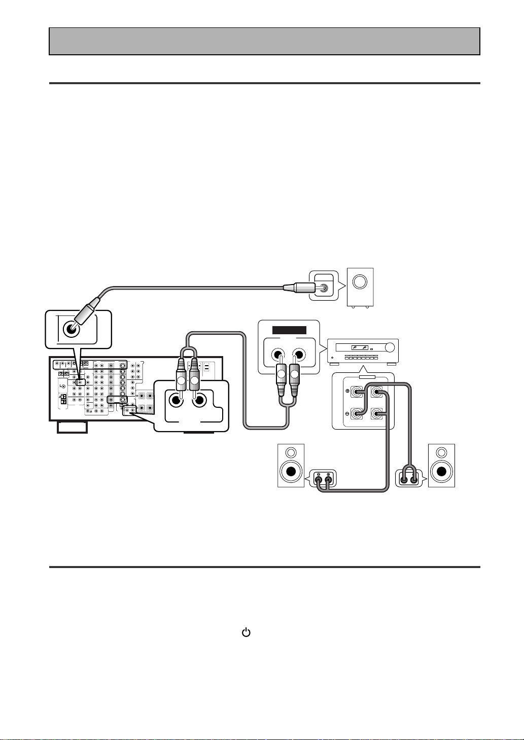
2 Speaker Connections
Home theater is designed to be setup with five, or seven speakers (front left & right; center; surround left &
right; and, optimally, surround back left & right) and a subwoofer but you can use this receiver with fewer
speakers. Hook up the speakers you have to the A speaker terminals on the back of the receiver. If you only
have two speakers hook them up as “FRONT“. If you have three hook up the single speaker as “CENTER“.
Follow the diagram on p.19 in order to hook up all your speakers. A center speaker is very important for
watching films because the dialog comes from the center speaker in digital soundtracks. If you do not have a
CENTER speaker you must tell the receiver the CENTER channel is OFF or when you listen to digital
soundtracks you won't hear any dialog. Use the instructions on page 33-34 in order to do this.
Follow the diagram below to hook up an additional amplifier in order to use surround back speakers. These
speakers are important to hear all the sound channels on new, eight channel home theater DVDs. The diagram
below also explains how to hook up a subwoofer which provides realistic bass sounds.
Make sure you connect the speaker on the right to the right terminal and the speaker on the left to the left
terminal. Also make sure the positive and negative (+/–) terminals on the amplifier match those on the speakers.
33
33
3 Setting up the Remote Control & Unit
1 Put the batteries in the remote control.
2 Plug the main unit into a wall outlet.
3 Press
_ ON/ — OFF button and the STANDBY/ON button on the receiver to
put the receiver in ON mode.
R
L (Single)
SURROUND
BACK
PRE OUT
SUB
WOOFER
Surround back
speaker (Right)
Surround back
speaker (Left)
INPUT
Powered
subwoofer
Additional Amplifier (See p.21)
INPUT
L
L
R
R
ANALOG
FRONT
SPEAKERS
L
L
R
R
RCA stereo cord
RCA audio cord
V
En
Quick Start Guide
44
44
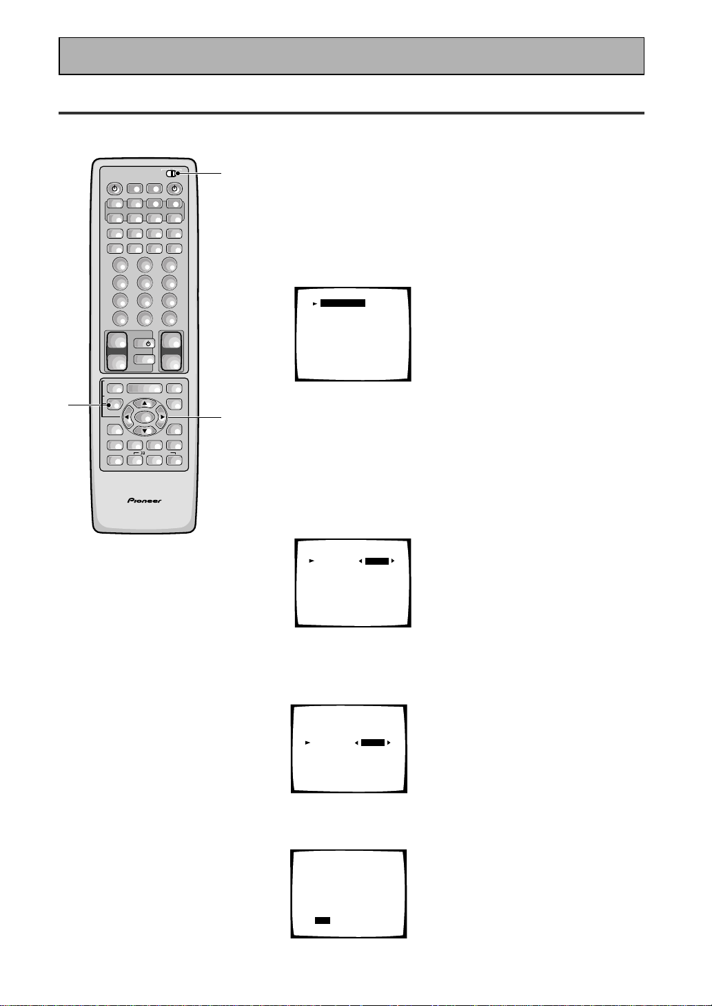
4 Digital Input Assignment
This is only necessary if you did not hook up your DVD to DIGITAL IN 1, as in the first diagram on p.III
1 Set the remote control slide switch to SETUP.
Also make sure your TV is on and set to the receiver.
• When you're done setting up the receiver, remember to set
the slide switch back to USE.
2 Press the SYSTEM SETUP button.
You should see the following display on your TV.
System Setup
[Digital-In Select]
[Speaker Setting]
[Channel Delay]
[Channel Level]
[Crossover Network]
[Bass Peak Level]
[D-Range Control]
[Multi Channel In]
• You can escape from this screen at any time by pressing the
SYSTEM SETUP button again. None of the settings you
made will be entered in this case.
• If don't enter any settings the receiver will revert back to its
previous state after three minutes.
3 Digital in Select should be selected (if it isn't use
the 5¥∞ buttons to select it). Press ENTER.
You should see the following display on your TV.
Digital-In Select
Digital-1
Digital-2
Digital-3
Digital-4
Digital-5
AC-3 RF
[EXIT] L
[DVD/LD]
[ CD ]
[ MD ]
[TV/SAT ]
[ VCR1 ]
[DVD/LD]
4 Choose the Digital-3 you hooked up your DVD
player to and assign "DVD/LD" to it.
Use the 2 or 3 buttons to choose the DVD/LD setting.
5 Select EXIT with 5¥∞ buttons and press ENTER
to return to the SYSTEM SETUP MENU.
AV PRE-PROGRAMMED AND LEARNING
REMOTE CONTROL UNIT
3-5
1
2
/DTS/MPEG
S0URCE
DVD/LD TV/SAT VCR1 VCR2
CD
TV VOL
TV FUNC
MENU
ENTER
STEREO/
DIRECT
DSP
THXLIGHT
MUTE
TV
VOLUME
MD/
TAPE1
TUNER TVCONT
RECEIVER
USE SETUP
MULTI
OPERATION
CLASS MPX
DIRECT ACCESS
CHANNEL
STATION
TUNING
DISPLAY
RF ATT
TV CONTROL
FUNCTION
REMOTE SETUP
SYSTEM SETUP
INPUT
ATT
ADVANCED
MIDNIGHT
MULTI CH
INPUT
STANDARD
DIGITAL
NR
EFFECT/
CH SEL
SIGNAL
SELECT
BAND
SYSTEM
OFF
123
456
789
0
DISC
Î
873
1¡4¢
+
-
+
-
+
-
MULTI CONTROL
++
––
+
–
+10
Digital-In Select
Digital-1
Digital-2
Digital-3
Digital-4
Digital-5
AC-3 RF
[EXIT] L
[DVD/LD]
[ CD ]
[DVD/LD]
[TV/SAT ]
[ VCR1 ]
[DVD/LD]
Digital-In Select
Digital-1
Digital-2
Digital-3
Digital-4
Digital-5
AC-3 RF
[EXIT] L
[ OFF ]
[ CD ]
[DVD/LD]
[TV/SAT ]
[ VCR1 ]
[DVD/LD]
VI
En
Quick Start Guide
66
66
6 For Better Surround Sound
1 Go through the entire "system setup" procedures as outlined on pages 12-21
of this instruction manual.
If you don't hook up any other components with digital audio or do so following the default settings of
the receiver (see page 14) you won't have to assign any more digital inputs, but many other adjust-
ments will improve the sound tremendously.
2 Experiment with the different sound settings offered with the 2/DTS/MPEG
and DSP buttons.
For more information see pages 42-46.
3 As mentioned above you should go through the "speaker setup" instructions
on pages 29-41 to set up your speakers properly. If you don't do this you, at
least, need to make sure the CENTER channel is turned off if you don't have a
center speaker. Use the instructions on pages 30-34.
Speaker Setting
[FREE] [THX]
[LARGE]
[LARGE]
[LARGE]
[LARGEx2]
[ YES ]
Front L
Center
Surround
SurrBack
Subwoofer
[EXIT]
55
55
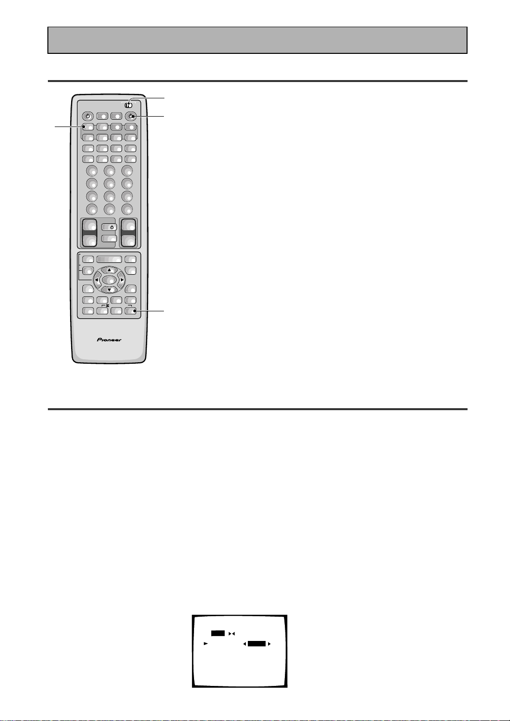
5 Playing a DVD with Surround Sound
AV PRE-PROGRAMMED AND LEARNING
REMOTE CONTROL UNIT
1
2
3
2
/DTS/MPEG
S0URCE
DVD/LD TV/SAT VCR1 VCR2
CD
TV VOL
TV FUNC
MENU
ENTER
STEREO/
DIRECT
DSP
THXLIGHT
MUTE
TV
VOLUME
MD/
TAPE1
TUNER TVCONT
RECEIVER
USE SETUP
MULTI
OPERATION
CLASS MPX
DIRECT ACCESS
CHANNEL
STATION
TUNING
DISPLAY
RF ATT
TV CONTROL
FUNCTION
REMOTE SETUP
SYSTEM SETUP
INPUT
ATT
ADVANCED
MIDNIGHT
MULTI CH
INPUT
STANDARD
DIGITAL
NR
EFFECT/
CH SEL
SIGNAL
SELECT
BAND
SYSTEM
OFF
123
456
789
0
DISC
Î
873
1¡4¢
+
-
+
-
+
-
MULTI CONTROL
++
––
+
–
+10
Set the remote control slide switch to USE.
1 Turn on the receiver, your TV, and the DVD player.
2 Press the DVD/LD button on the remote control.
You should see "DVD/LD" in the display on the receiver.
3 Press the STANDARD button for the basic
surround sound setting.
4 Play a DVD.
7
En
PREPARATION
Table of Contents
Before You Start ................................... 9
Checking the Supplied Accessories .......................... 9
How to Use This Manual ............................................ 9
Preparing the Remote Control ................................... 9
Loading the batteries .............................................. 9
Operating range of remote control unit .............. 10
Operating other PIONEER components .............. 10
Installing the Receiver .............................................. 11
Ventilation ............................................................. 11
Opening the Front Panel .......................................... 11
Connecting Your Equipment ............. 12
Audio Components ................................................... 12
Cassette deck placement ...................................... 12
Digital Connections .................................................. 13
Example Connection for a DVD/LD or LD player .... 14
Digital Input Assignment ..................................... 14
Video Components ................................................... 15
Satellite TV Components ......................................... 16
TV ............................................................................... 17
Multi Channel Input (External Decoder) ................. 17
Connecting the Radio Antennas .............................. 18
Using external antennas ...................................... 18
Speakers .................................................................... 19
Speaker impedance .............................................. 20
Placing Your Speakers .............................................. 20
Speaker placement ............................................... 20
Connecting Additional Amplifiers ........................... 21
Plugging In (Except for the U.K. model) ................. 21
Displays & Controls ........................... 22
Display ....................................................................... 22
Remote Control ......................................................... 24
Front Panel ................................................................ 26
Initial Set Up ....................................... 29
On Screen Display .................................................... 29
Switching video system between
PAL and NTSC .................................................. 29
Setting Up for Surround Sound .............................. 30
Digital-In Select ..................................................... 32
Speaker Setting ..................................................... 33
Channel Delay ....................................................... 35
Channel Level ........................................................ 36
Crossover Network ............................................... 38
Bass Peak Level ..................................................... 39
Dynamic Range Control ....................................... 40
Multi Channel In Setting ...................................... 41
Multi Channel In Setting Using the Main Unit ... 41
Basic Playback .................................... 42
Sound Modes ............................................................ 42
Selecting a Sound Mode .......................................... 45
Playing Sources with Dolby Digital,
DTS or MPEG .......................................................... 46
Playing Stereo Sources ............................................ 47
Switching Analog and Digital Signal Input ............ 48
Reducing Noise During Playback ............................ 49
Listening in Midnight Mode ..................................... 50
Using the Loudness Mode ....................................... 50
Adjusting Bass and Treble ....................................... 51
MULTI CHANNEL IN Playback ................................. 52
96kHz 24bit Performance ......................................... 52
Direct Playback .......................................................... 53
Adjusting the Brightness of the Display ................. 53
DUAL MONO Setting ................................................ 54
Using the Tuner .................................. 55
Automatic and Manual Tuning ................................ 55
MPX mode ............................................................. 55
RF ATT mode......................................................... 55
Direct Access Tuning ................................................ 56
Memorizing Frequently Used Stations ................... 57
Recalling Memorized Stations ................................. 58
Using the remote control ..................................... 58
Using the front panel ............................................ 58
Memorizing a broadcast station name
(Manual Station Name Memory) ..................... 59
To erase and change the memorized
station name ..................................................... 59
An Introduction to RDS & EON ................................ 60
Basics of EON ........................................................ 61
The receiver’s internal Program
Identification function ...................................... 61
RDS (Radio Data System) Broadcast Reception .... 62
Displaying RDS data ............................................. 62
Searching for a program by
program type (PTY) .......................................... 63
Using EON search ................................................. 64
Remote Control of Other Components ...
65
Setting Up the Remote Control to Control Other
Components .............................................................. 65
Recalling Preset Codes ......................................... 65
Learning Commands from Other
Remote Controls ............................................... 67
Using the Remote Control with Other
Components ............................................................ 69
Using Other Functions....................... 76
Recording from Audio Components ....................... 76
Record monitor (TAPE 2 MONITOR) ................... 76
Recording from Digital Audio Components ........... 77
Recording from Video Components ....................... 77
Multi Operations ....................................................... 78
Performing Multi Operations ............................... 79
System Off ................................................................. 80
Using the System Off Button ............................... 81
Setting Up the Direct Function ................................ 81
Remote Back Light .................................................... 82
Resetting the Remote Control ................................. 82
Erasing Multi Operations ..................................... 82
Erasing Learned Remote Control Commands ........ 83
Erasing All Learned Commands and
Preset Codes ........................................................... 83
Video Select .............................................................. 84
Techno Tidbits & Problem-solving.... 85
Preset Code List ........................................................ 88
Troubleshooting ........................................................ 92
Specifications ............................................................ 95
OPERATION
SET
UP
8
En
Features
Multi Channel Stereophonic Concept
The VSX-909RDS/909RDS-G receiver is constructed with Pioneer’s industry-leading multi channel stereophonic
concept. This well-developed approach to receiver circuitry takes the high level base technology that, up until
now, has been only used for stereo equipment and applies it to multi-channel audio-visual receivers. The result
is that the product, in addition to being expertly built, and gives you optimal sound reproduction of DVDs, other
multi channel sources and stereo sources as well. This receiver is designed capture to a true reproduction of the
intentions of a filmmaker or music producer at the time they were mastering the soundtrack in the studio. It
incorporates 5 independent 110 watt built in power amplifiers, with high-performance Hex power Direct Power
MOS FET output transistors. This construction provides improved linearity and accurate representation of each
channel for true high fidelity reproduction from even the most demanding Dolby Digital and DTS program
sources. In addition, the amplifier uses Direct Construction to give the purest sound available. All these
elements consolidated in one receiver afford the listener a new surround sound experience in his or her home.
Universal Player Compatibility
This receiver incorporates the latest technology and is able to handle cutting edge audio formats, like DVD
Audio, which are just hitting the market. Its high compatibility offers a variety of inputs to decode all types of
sources at the highest possible quality. The receiver’s multi channel in connections lets you hook up eight
discrete channels of audio. It also has multi channel direct inputs and the ability to decode the cutting edge
formats.
Decoding of Next Generation Digital Source Film Formats
Built into this receiver is the latest in film sound format technology. This technology includes the recent THX
SURROUND EX and HOME THX CINEMA surround modes which employ special processing to allow you to
enjoy movie soundtracks with the same level of power and realism you experience in well-designed movie
theaters. The THX SURROUND EX mode has been especially designed to incorporate surround back channels
that some new source material uses. This receiver has the ability to decode Dolby Digital, Dolby Pro Logic,
MPEG and DTS (Digital Theater Systems) sources, which are the standards of home theater today. It also offers
component video terminals for the sharpest video transmission available to the consumer.
Advanced Theater Modes & DSP Surround Modes
Advanced Theater modes enhance the sound of either film or music so a more dramatic effect can be achieved.
The four modes are each designed to accentuate specific sound qualities, giving the listener a wide range of
possibilities. DSP (Digital Signal Processing) surround modes give you the capability of transforming your living
room into seven different sonic environments when listening to music.
RDS (Radio Data System)
With the RDS system, FM station can send additional signals with their regular program signals. For example,
the stations send their station names, and information about the type of programs they broadcast, such as
news, sport or music. This unit receives three types of RDS signals: RT, PS, and PTY.
The Energy-saving Design
This unit is designed to use less than 1 W of energy when the receiver is in standby mode.
“DTS”, "ES" and “DTS Digital Surround” are
trademarks of Digital Theater Systems, Inc.
Manufactured under licence from Digital Theater
Systems, Inc.
Manufactured under license from Dolby Laboratories.
“Dolby”, “AC-3”, “Pro Logic”, and double-D symbol
are trademarks of Dolby Laboratories. Confidential
unpublished works. © 1992 - 1997 Dolby Laboratories.
All rights reserved.
Manufactured under license from Lucasfilm Ltd. U.S.
patent numbers 5,043,970; 5,189,703; and/or
5,222,059. European patent number 0323830. Other
U.S. and foreign patents pending. Lucasfilm and THX
are registered trademarks of Lucasfilm Ltd. Surround
EX is a trademark of Dolby Labs. Used under
authorization.
The MPEG logo is a registered trademark of Royal
Philips Electronics.
9
En
PREPARATION
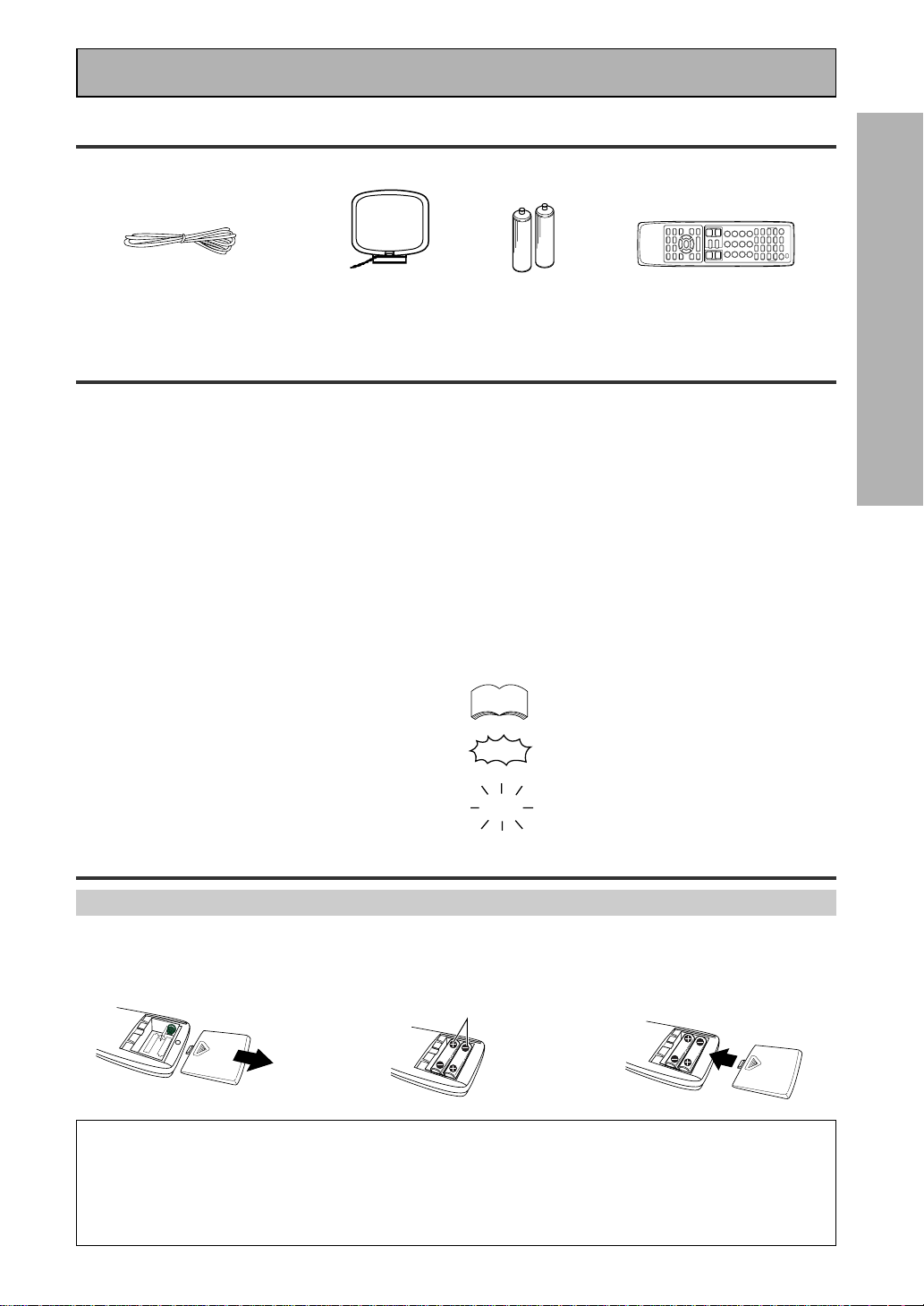
Checking the Supplied Accessories
Please check that you have received all of the following supplied accessories.
How to Use This Manual
This manual is for the VSX-909RDS/909RDS-G Audio/
Video Multi-Channel Receiver.
This manual is divided into three main sections which
will tell you how to setup and use the unit :
PREPARATION
First carry out the tasks below in this “Before You
Start“ section to prepare the remote control, then
connect the receiver to your other components as
described in “Connecting Your Equipment“ (p.12).
Take special care to connect your digital equipment
like DVDs and LDs properly to be able to take
advantage of the receiver’s surround sound systems
(p.13-14). To learn about a specific button, control, or
indicator, see “Displays & Controls“ starting on p.22.
SET UP
Performing the tasks in “Initial Set Up“ (from p.29) is
essential to get proper surround sound.
“AA” IEC LR6
batteries x 2
FM wire antenna
AM loop antenna
1
2
3
\
\
Remote control unit
Before You Start
memo
OPERATION
To play some music or soundtrack refer to “Basic
Playback“ on p.42. “Using the Tuner“ (p.55) explains
how to use the radio of this unit. Doing the operations
in “Remote Control of Other Components“ (p.65) is
highly recommended so you can use this unit’s
remote control for all your components. “Using Other
Functions“ (p.76) explain the other possibilities of the
receiver.
“Techno Tidbits & Problem-solving“ (p.85) provide
detailed technical information and a troubleshooting
guide.
The following marks and symbols are used throughout
the manual:
Provides additional information,
precautions, and advice.
Indicates a blinking button, indicator, or
display.
Indicates a steadily lit button, indicator, or
display.
• Operating Instructions
"AA" IEC LR6
batteries x 2
Preparing the Remote Control
Loading the batteries
Load the batteries into the remote control as shown below. Please use alkaline batteries. When you notice a
decrease in the operating range of the remote control, replace all batteries with new ones.
CAUTION!
Incorrect use of batteries may result in such hazards as leakage and bursting. Observe the following precautions.
• Never use new and old batteries together.
• Insert the plus and minus sides of the batteries properly according to the marks in the battery case.
• Batteries with the same shape may have different voltages. Do not use different batteries together.
• When disposing of used batteries, please comply with governmental regulations or environmental public institution’s
rules that apply in your country or area.
10
En
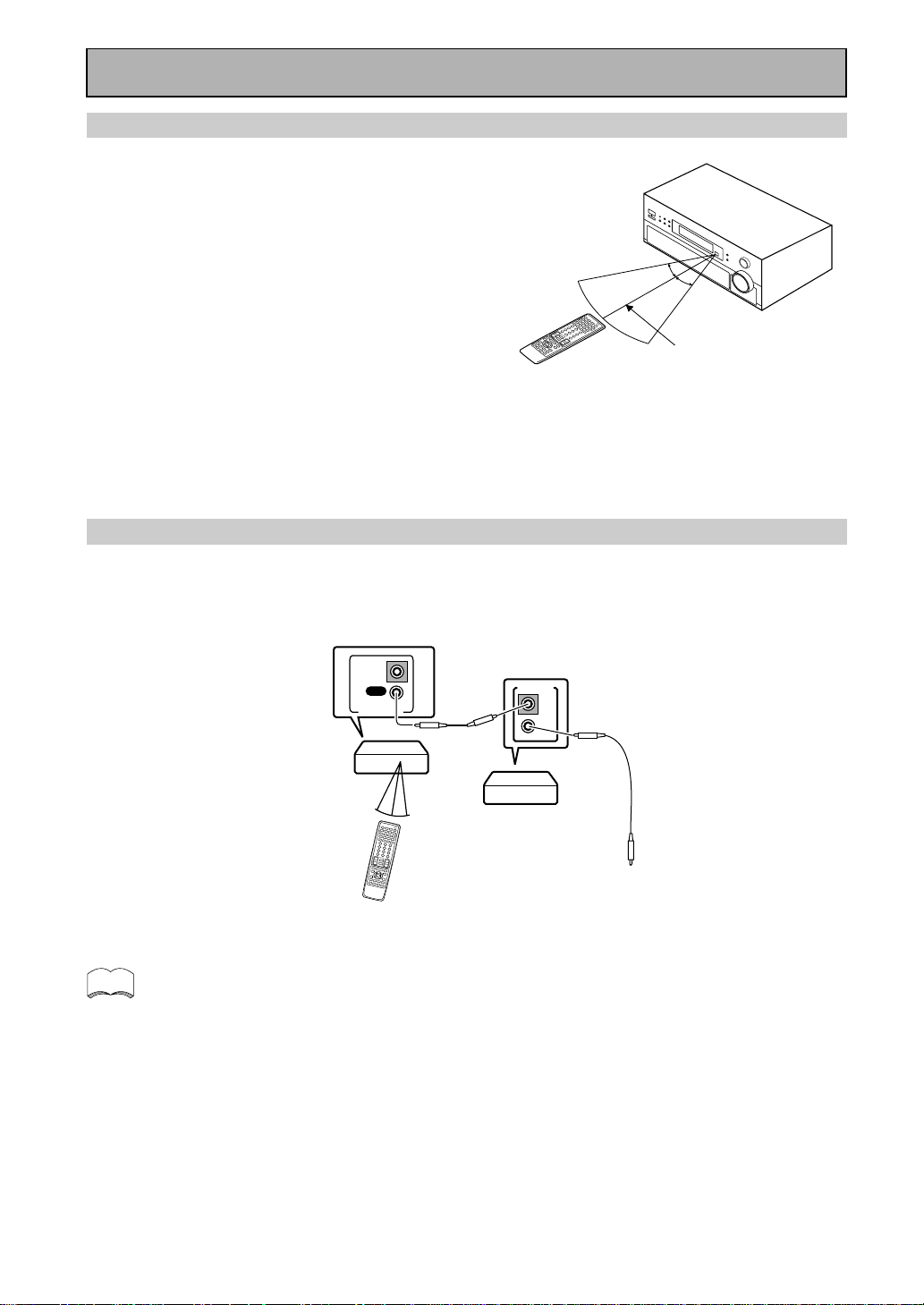
Operating range of remote control unit
The area in which you can use the remote control to operate
the VSX-909RDS/909RDS-G is fairly large. To use, point the
remote control toward the remote sensor on the front panel of
this unit while within the range shown right.
Remote control may not function properly if:
• There are obstacles between the remote control and the
remote sensor.
• Direct sunlight or fluorescent light is shining onto the
remote sensor.
• The receiver located near a device emitting infrared rays.
• Operated simultaneously with another remote control which
uses infrared rays.
30°
30°
7m
Before You Start
memo
OUT
IN
CONTROL
OUT
IN
CONTROL
PIONEER component
bearing the Î mark.
Remote Control
To CONTROL IN
terminal of another
PIONEER component
bearing the Î mark.
Receiver
• You can also control PIONEER components (and those made by other manufacturers) by pointing the
receiver’s remote control directly at the respective components. This type of operation does not require
control cords. All you have to do is recall the appropriate preset code (refer to “Recalling preset
codes” on page 65).
• If you use a remote control hooked up via the CONTROL IN jack with a control cord, you won't be able
to use this unit's remote control.
Operating other PIONEER components
Connecting an optional control cord allows you to operate other PIONEER components simply by pointing the
receiver’s remote control at the remote sensor on the front panel of the receiver. The receiver then sends the
remote control signals to the other components via the CONTROL OUT terminal.
11
En
PREPARATION
Before You Start
Installing the Receiver
Ventilation
• When installing this unit, make sure to leave space around the unit for ventilation to improve heat radiation (at
least 60 cm at the top, 10 cm at the rear, and 30 cm at each side). If not enough space is provided between
the unit and walls or other equipment, heat will build up inside, interfering with performance or causing
malfunctions.
• Do not place on a thick carpet, bed, sofa or fabric having a thick pile. Do not cover with fabric or other
covering.
Anything that blocks ventilation will cause the internal temperature to rise, which may lead to breakdown or
fire hazard.
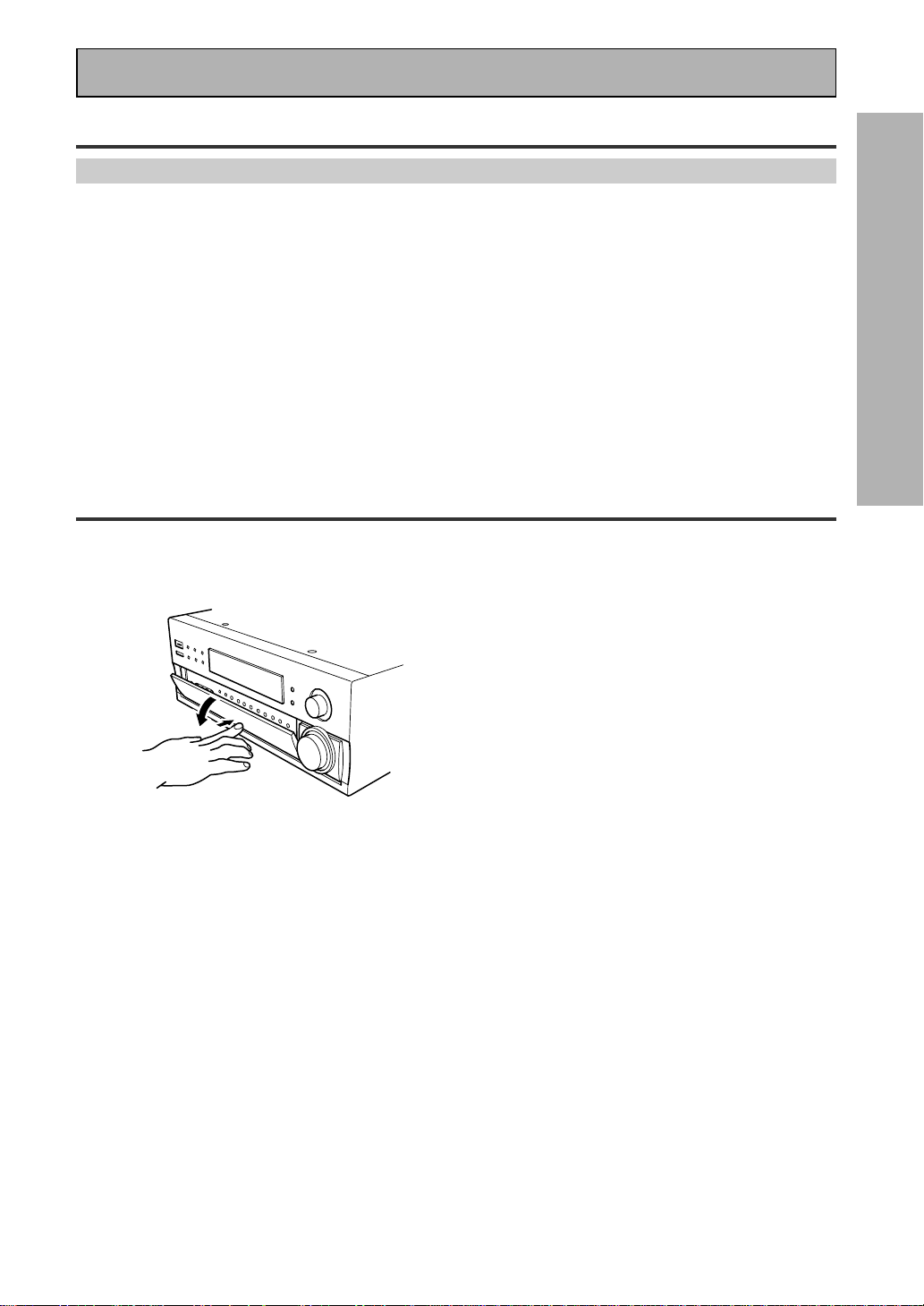
Opening the Front Panel
To open the front panel push gently on the lower third of the panel with your finger.
12
En
Connecting Your Equipment
Cassette deck placement
Depending on where the cassette deck is placed,
noise may occur during playback of your cassette
deck which is caused by leakage flux from the
transformer in the receiver. If you experience noise,
move the cassette deck farther away from the
receiver.
7 Audio cords
Use audio cords (not supplied) to connect the
audio components.
Connect red plugs to R (right)
and white plugs to L (left).
Be sure to insert completely.
L
R
Before making or changing the connections, switch off the power and
disconnect the power cord from the AC outlet.
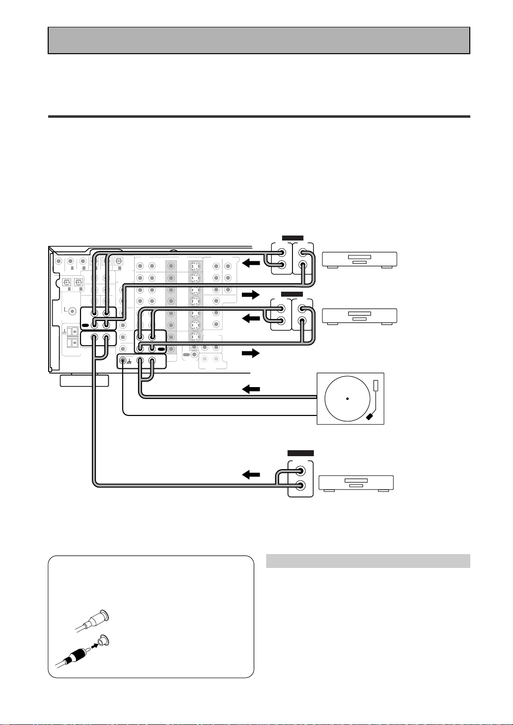
Audio Components
To begin set up connect your audio components to the jacks as shown below. These are all analog connections
and your analog audio components (turntable, cassette deck) use these jacks. Remember that for components
you want to record with you need to hook up four plugs (a set of stereo ins and a set of stereo outs), but for
components that only play (like a turntable) you only need to hook up one set of stereo plugs (two plugs). To use
DTS or Dolby Digital surround sound features you must hook up your digital components to the digital inputs
(see p.13). We also recommend hooking up your digital components to analog audio jacks. If you want to record
to/from digital components (like an MD) to/from analog components you must hook up your digital equipment
with these analog connections. See p.13 & 14 for more on digital connections.
*The arrows indicate the direction of the audio signal.
If your turntable
has a ground
wire, connect it
to the SIGNAL
GND terminal.
CD
IN
SURR-
OUND
SUB
WOOFER
CENTER
FRONT
MULTI CH IN
SURR-
OUND
RL
R
L
R
L
R
L
R
L (Single)
R
R
L
L
R
L
R
L
FRONT
AUDIO
SUB
WOOFER
PRE OUT
CENTER
COMPONENT VIDEO
DVD/LD
IN
TV/SAT
IN
Y
P
B
P
R
MONITOR
OUT
MONITOR
OUT 1
MONITOR
OUT 2
P
B
P
R
Y
MULTI CH IN
SURROUND
BACK
SURROUND
BACK
PRE OUT
DVD /
LD
IN
S VIDEOVIDEO
VIDEOAUDIO
IN
TV /
SAT
IN
IN
OUT
IN
VCR1 /
DVR
OUT
IN
OUT
IN
VCR2
OUT
IN
CONTROL
IN
OUT
MD /
TAPE1/
CD-R
PLAY
REC
TAPE2
MONITOR
PLAY
REC
PCM/
2
/
DTS/
MPEG
DIGITAL
IN
5
IN
4
IN
3
2
RF IN
(AC-3)
IN
2
IN
1
IN
PHONO
FM UNBAL
75‰
FM
ANTENNA
AM LOOP
ANTENNA
OUTOUT
21
CD player
Turntable
OUTPUT
L
R
ANALOG
Recorder 1(MD/Tape)
OUTPUT
(PLAY)
L
R
INPUT
(REC)
L
R
ANALOG
Recorder 2(MD/Tape)
OUTPUT
(PLAY)
L
R
INPUT
(REC)
L
R
ANALOG
Please don't hook up any other component to the phono jacks other than a turntable. It could damage the
equipment. If your turntable has a built-in amplifier please hook it up to an input other than PHONO.
13
En
PREPARATION
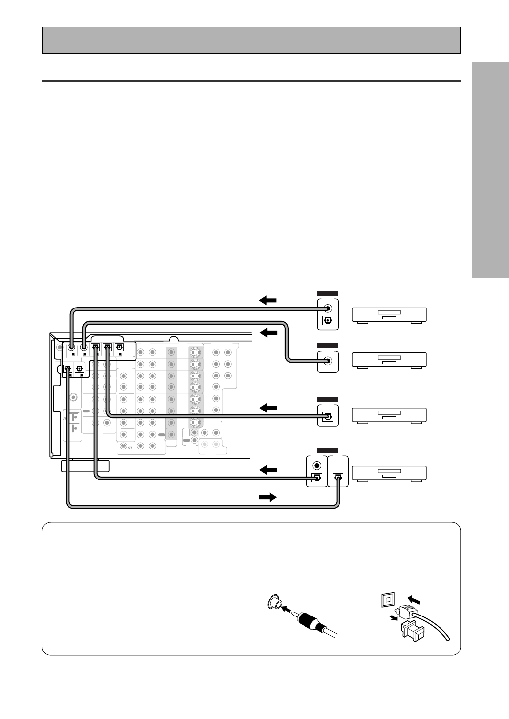
Digital Connections
In order to use Dolby Digital/DTS soundtracks which are at the heart of home theater you need to make digital
audio connections. You can do this by either a coaxial or an optical connection (you don’t need to do both). The
quality of these two types of connections is the same but since some digital components only have one type of
digital terminal, it is a matter of matching like with like (for example, the coaxial out from the component to
coaxial in on the receiver). The receiver has two coaxial and three optical inputs for a total of five digital inputs. A
DVD/LD player or LD player should be connected to a digital jack and the special 2 RF jack (if the LD has one)
as well as a pair of analog jacks (see the next page). If possible, hook up your digital equipment in accordance
with this receiver's default settings. See “Digital Input Assignment“ below left, in order to do this.We also
recommend hooking up your digital components to analog audio jacks in order to make recording from some
digital sources which may be copy protected.
Connect your digital components as shown below.
There are two optical digital out jacks (the MD recorder is connected to one in the diagram below). If you
connect this to the optical input on a digital recorder (currently these include MD, DAT and CD-R) you can make
direct digital recordings with this unit.
Before making or changing the connections, switch off the power and disconnect the power cord from the AC
outlet.
*The arrows indicate the direction of the audio signal.
CD
IN
SURR-
OUND
SUB
WOOFER
CENTER
FRONT
MULTI CH IN
SURR-
OUND
RL
R
L
R
L
R
L
R
L (Single)
R
R
L
L
R
L
R
L
FRONT
AUDIO
SUB
WOOFER
PRE OUT
CENTER
COMPONENT VIDEO
DVD/LD
IN
TV/SAT
IN
Y
P
B
P
R
MONITOR
OUT
MONITOR
OUT 1
MONITOR
OUT 2
P
B
P
R
Y
MULTI CH IN
SURROUND
BACK
SURROUND
BACK
PRE OUT
DVD /
LD
IN
S VIDEOVIDEO
VIDEOAUDIO
IN
TV /
SAT
IN
IN
OUT
IN
VCR1 /
DVR
OUT
IN
OUT
IN
VCR2
OUT
IN
CONTROL
IN
OUT
MD /
TAPE1/
CD-R
PLAY
REC
TAPE2
MONITOR
PLAY
REC
PCM/
2
/
DTS/
MPEG
DIGITAL
IN
5
IN
4
IN
3
2
RF IN
(AC-3)
IN
2
IN
1
IN
PHONO
FM UNBAL
75‰
FM
ANTENNA
AM LOOP
ANTENNA
OUTOUT
21
MD recorder
OUTPUT
(PLAY)
INPUT
(REC)
DIGITAL
TV tuner
DVD player
OUTPUT
DIGITAL
OUTPUT
DIGITAL
CD player
OUTPUT
DIGITAL
Connecting Your Equipment
7 Coaxial cords/Optical cables
Commercially available digital audio coaxial
cords (standard video cords can also be
used) or optical cables (not supplied) are
used to connect digital components to this
receiver.
When you use optical digital input or output
terminals, pull off the caps and insert the
plugs. Be sure to insert completely.
Coaxial cord
(or standard video cord)
Optical cable
(not a PCM-only output)
14
En
memo
CD
IN
SURR-
OUND
SUB
WOOFER
CENTER
FRONT
MULTI CH IN
SURR-
OUND
RL
R
L
R
L
R
L
R
L (Single)
R
R
L
L
R
L
R
L
FRONT
AUDIO
SUB
WOOFER
PRE OUT
CENTER
COMPONENT VIDEO
DVD/LD
IN
TV/SAT
IN
Y
Y
P
B
P
R
MONITOR
OUT
MONITOR
OUT 1
MONITOR
OUT 2
P
B
P
R
Y
MULTI CH IN
SURROUND
BACK
SURROUND
BACK
PRE OUT
DVD /
LD
IN
S VIDEOVIDEO
VIDEOAUDIO
IN
TV /
SAT
IN
IN
OUT
IN
VCR1 /
DVR
OUT
IN
OUT
IN
VCR2
OUT
IN
CONTROL
IN
OUT
MD /
TAPE1/
CD-R
PLAY
REC
TAPE2
MONITOR
PLAY
REC
PCM/
2
/
DTS/
MPEG
DIGITAL
IN
5
IN
4
IN
3
2
RF IN
(AC-3)
IN
2
IN
1
IN
PHONO
FM UNBAL
75‰
FM
ANTENNA
AM LOOP
ANTENNA
OUTOUT
21
DVD/LD player
or LD player
1
23
DIGITAL OUT
(AC-3)(LD)
RF OUT
2
COMPO-
NENT
VIDEO
OUT
VIDEO
S-VIDEO
P
B
P
R
STEREO
L
R
ANALOG
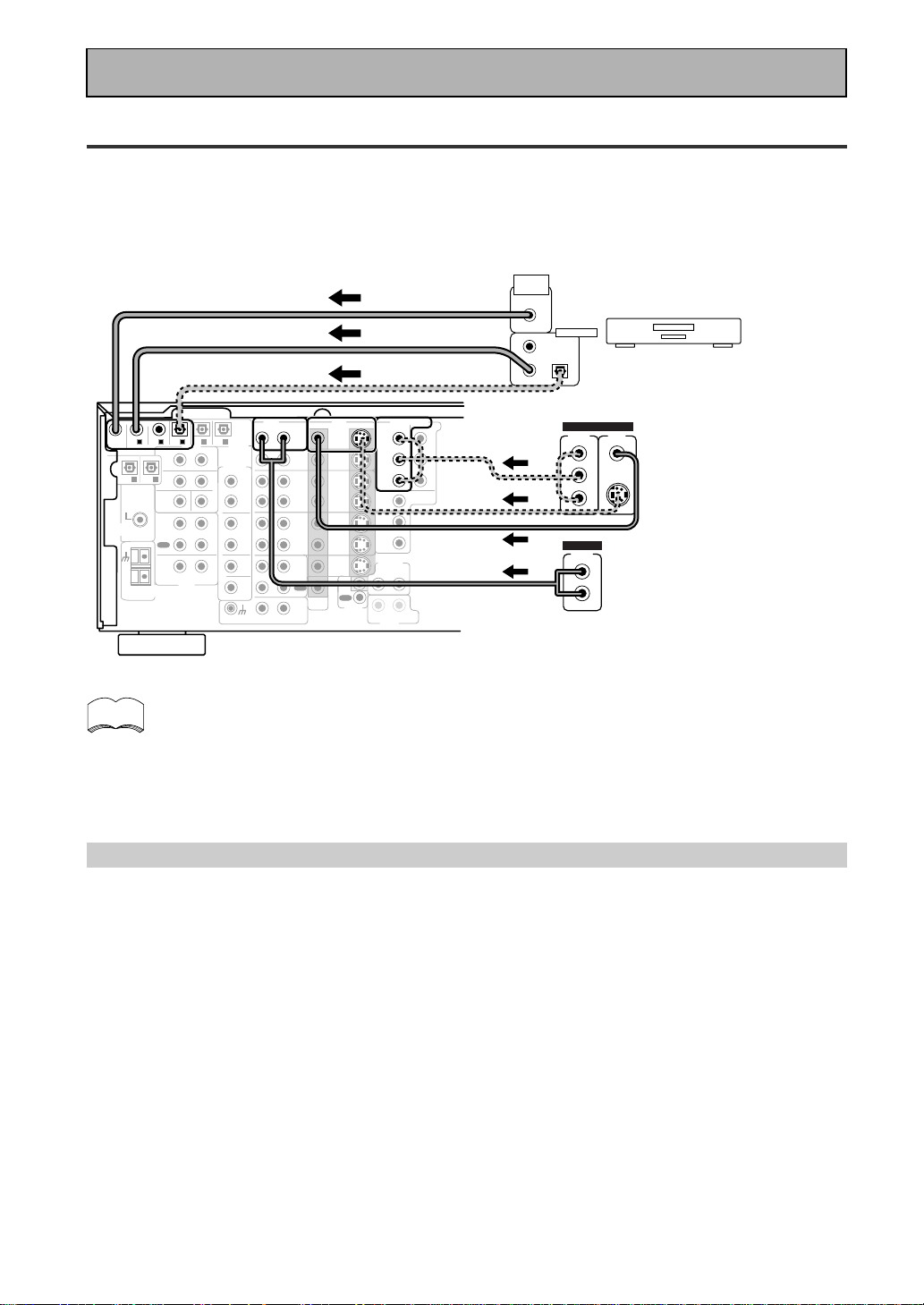
Connecting Your Equipment
Example Connection for a DVD/LD or LD player
Make sure you connect your DVD/LD or LD players using both the 2 RF jack and either a coaxial or optical (you
don't need to do both of these) digital connections. If your player has an 2 RF output this will ensure you can
use all LDs (see p.15). We also recommend hooking up your digital components to analog audio jacks.
Before making or changing the connections, switch off the power and disconnect the power cord from the AC
outlet.
*The arrows indicate the direction of the audio signal.
Be sure to make either a digital coaxial or digital optical connection (pictured as DIGITAL jack 1
or DIGITAL jack 3 in this diagram) as well, but you DON'T need to make both.
Also, be sure to assign the jacks to the proper component(s) with the
Digital-In Select
procedure
(see p.32) if necessary. See the explanation below for details.
(not a PCM-only output)
Digital Input Assignment
Unlike analog connections, the jacks for digital connections are not dedicated to one type of component, they
can be used freely. Thus you must tell the receiver what digital component in which jack so your components
will be in sync with the the names on the remote control buttons and the like. To avoid having to assign the
digital inputs you can hook up your equipment in accordance with the receiver's default settings.
The default settings are:
DIGITAL IN 1: DVD/LD
DIGITAL IN 2: CD
DIGITAL IN 3: MD
DIGITAL IN 4: TV/SAT
DIGITAL IN 5: VCR1
AC-3 RF: DVD/LD
You will notice that Digital IN 1, for example, is a coaxial jack. If your DVD/LD player only has an optical out jack on
it then you won't be able to hook up your components in accordance with the VSX-909RDS/909RDS-G default
setting. In this case you will need to assign the digital inputs. See
Digital-In Select
on p.32 in order to do this.
15
En
PREPARATION
CD
IN
SURR-
OUND
SUB
WOOFER
CENTER
FRONT
MULTI CH IN
SURR-
OUND
RL
R
L
R
L
R
L
R
L (Single)
R
R
L
L
R
L
R
L
FRONT
AUDIO
PRE OUT
CENTER
COMPONENT VIDEO
DVD/LD
IN
TV/SAT
IN
Y
P
B
P
R
MONITOR
OUT
MONITOR
OUT 1
MONITOR
OUT 2
P
B
P
R
Y
MULTI CH IN
SURROUND
BACK
SURROUND
BACK
PRE OUT
DVD /
LD
IN
S VIDEOVIDEO
VIDEOAUDIO
IN
TV /
SAT
IN
IN
OUT
IN
VCR1 /
DVR
OUT
IN
OUT
IN
VCR2
OUT
IN
CONTROL
IN
OUT
MD /
TAPE1/
CD-R
PLAY
REC
TAPE2
MONITOR
PLAY
REC
PCM/
2
/
DTS/
MPEG
DIGITAL
IN
5
IN
4
IN
3
2
RF IN
(AC-3)
IN
2
IN
1
IN
PHONO
FM UNBAL
75‰
FM
ANTENNA
AM LOOP
ANTENNA
OUTOUT
21
SUB
WOOFER
DVD/LD player
COMPO-
NENT
VIDEO
OUT
L
VIDEO
STEREO
L
R
DIGITAL
ANALOG
PCM/
2
/ DTS
DIGITAL
S-VIDEO
Y
P
B
P
R
RF OUT (LD)
2
RF OUT
(LD)
CD
IN
SURR-
OUND
SUB
WOOFER
CENTER
FRONT
MULTI CH IN
SURR-
OUND
RL
R
L
R
L
R
L
R
L (Single)
R
R
L
L
R
L
R
L
FRONT
AUDIO
PRE OUT
CENTER
COMPONENT VIDEO
DVD/LD
IN
TV/SAT
IN
Y
P
B
P
R
MONITOR
OUT
MONITOR
OUT 1
MONITOR
OUT 2
P
B
P
R
Y
MULTI CH IN
SURROUND
BACK
SURROUND
BACK
PRE OUT
DVD /
LD
IN
S VIDEOVIDEO
VIDEOAUDIO
IN
TV /
SAT
IN
IN
OUT
IN
VCR1 /
DVR
OUT
IN
OUT
IN
VCR2
OUT
IN
CONTROL
IN
OUT
MD /
TAPE1/
CD-R
PLAY
REC
TAPE2
MONITOR
PLAY
REC
PCM/
2
/
DTS/
MPEG
DIGITAL
IN
5
IN
4
IN
3
2
RF IN
(AC-3)
IN
2
IN
1
IN
PHONO
FM UNBAL
75‰
FM
ANTENNA
AM LOOP
ANTENNA
OUTOUT
21
SUB
WOOFER
PHONES
S-VIDEO VIDEO L AUDIO R
VIDEO INPUT
LV
R
VIDEO INPUT
VCR 1/DVR
VCR 2
VIDEO
S-VIDEO
VIDEO
S-VIDEO
AUDIO
(PLAY)
L
R
AUDIO
(REC)
L
R
S-VIDEO
VIDEOVIDEO
S-VIDEO
AUDIO
(PLAY)
L
R
AUDIO
(REC)
L
R
OUT IN
OUT IN
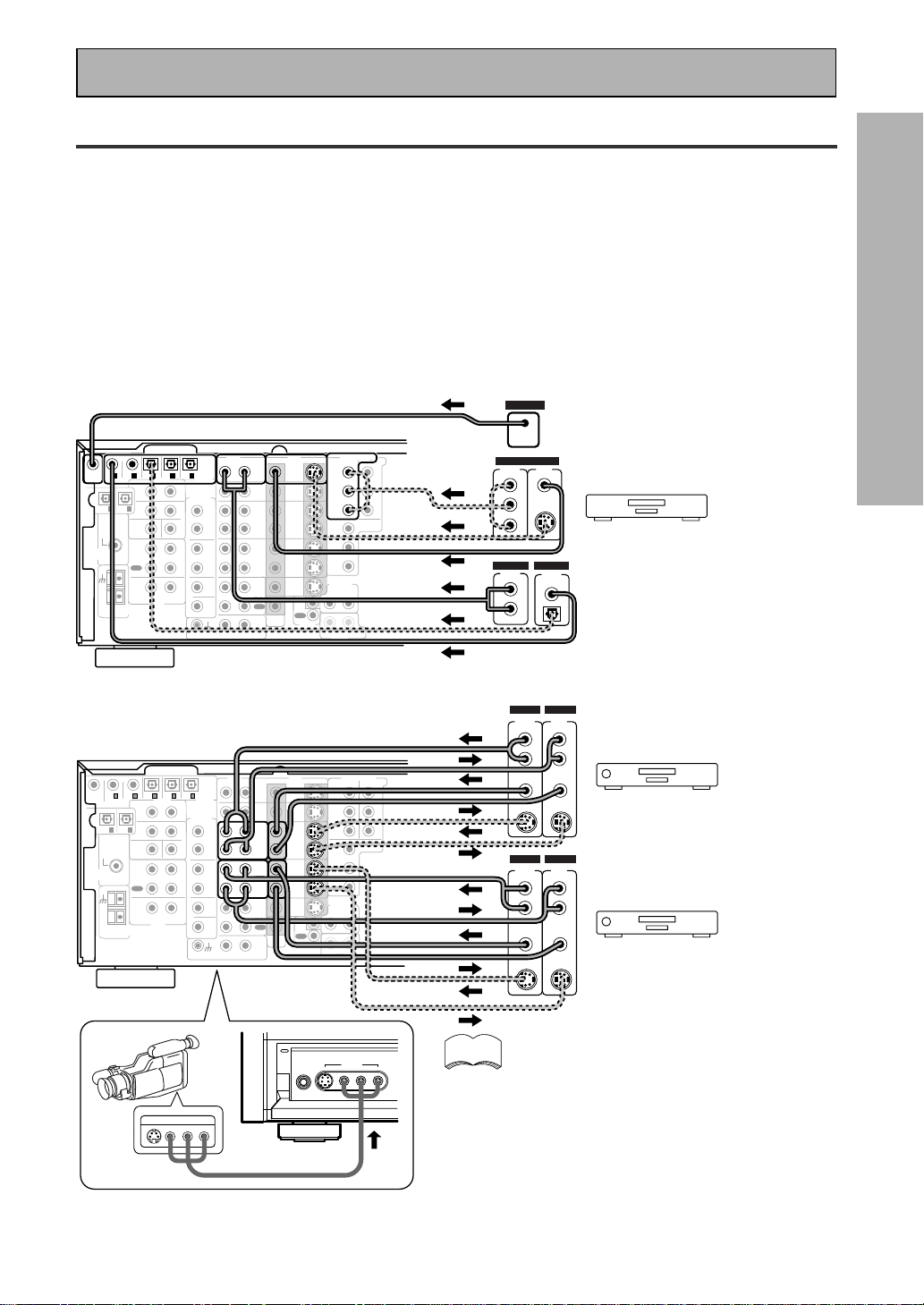
Connecting DVD/LD players
Connecting VCRs or DVRs
(LD player only)
Connecting Your Equipment
Video Components
Connect your video components to the jacks as shown below. Regarding a DVD there are two types of
connections to make. Hook up your video signal with either component video, S-video, or composite video cords
(the quality descends in this order) but remember, the video component you are watching and your TV must be
hooked up with same type of video cord or you won't be able to see the picture. For the audio signal, order to use
Dolby Digital/DTS you must hook up a digital input. It is also a good idea to hook up your DVD components with
analog audio connections as well, since some DVDs may not have a digital audio track. To cover all possible laser
discs a DVD/LD player or LD player requires an analog connection and two digital connections (a coaxial or optical
and a specialized 2 RF connection shown at the very top of the first diagram below).
Before making or changing the connections, switch off the power and disconnect the power cord from the AC
outlet.
*The arrows indicate the direction of the video signal.
(not a PCM-only output)
If you hook up your DVD/LD player
using component video
connections be sure to select
component video output on your
DVD player as well. See you DVD
manual for details.
Front video connections are accessed via the
front panel input selector as “VIDEO.“
If your video components have S-video jacks,
you could use S-video cords (not supplied) to connect
them on the back of the receiver. These jacks are
labeled by the Japanese designation
“
S2
“
on the VSX-
909RDS/909RDS-G but they are simply S-video jacks.
However, if you use S-video cords for your video hook
ups you must also hook up your TV with S-video
connections. Conversely, if you use regular composite
video cords for video hook ups, you should use them
for your TV as well.
memo
16
En
CD
IN
SURR-
OUND
SUB
WOOFER
CENTER
FRONT
MULTI CH IN
SURR-
OUND
RL
R
L
R
L
R
L
R
L (Single)
R
R
L
L
R
L
R
L
FRONT
AUDIO
PRE OUT
CENTER
COMPONENT VIDEO
DVD/LD
IN
TV/SAT
IN
Y
P
B
P
R
MONITOR
OUT
MONITOR
OUT 1
MONITOR
OUT 2
P
B
P
R
Y
MULTI CH IN
SURROUND
BACK
SURROUND
BACK
PRE OUT
DVD /
LD
IN
S VIDEOVIDEO
VIDEOAUDIO
IN
TV /
SAT
IN
IN
OUT
IN
VCR1 /
DVR
OUT
IN
OUT
IN
VCR2
OUT
IN
CONTROL
IN
OUT
MD /
TAPE1/
CD-R
PLAY
REC
TAPE2
MONITOR
PLAY
REC
PCM/
2
/
DTS/
MPEG
DIGITAL
IN
5
IN
4
IN
3
2
RF IN
(AC-3)
IN
2
IN
1
IN
PHONO
FM UNBAL
75‰
FM
ANTENNA
AM LOOP
ANTENNA
OUTOUT
21
TV/Satellite tuner
COMPO-
NENT
VIDEO
OUT
L
VIDEO
STEREO
L
R
DIGITAL
ANALOG
PCM/
2
/ DTS
DIGITAL
S-VIDEO
Y
P
B
P
R
SUB
WOOFER
Connecting Your Equipment
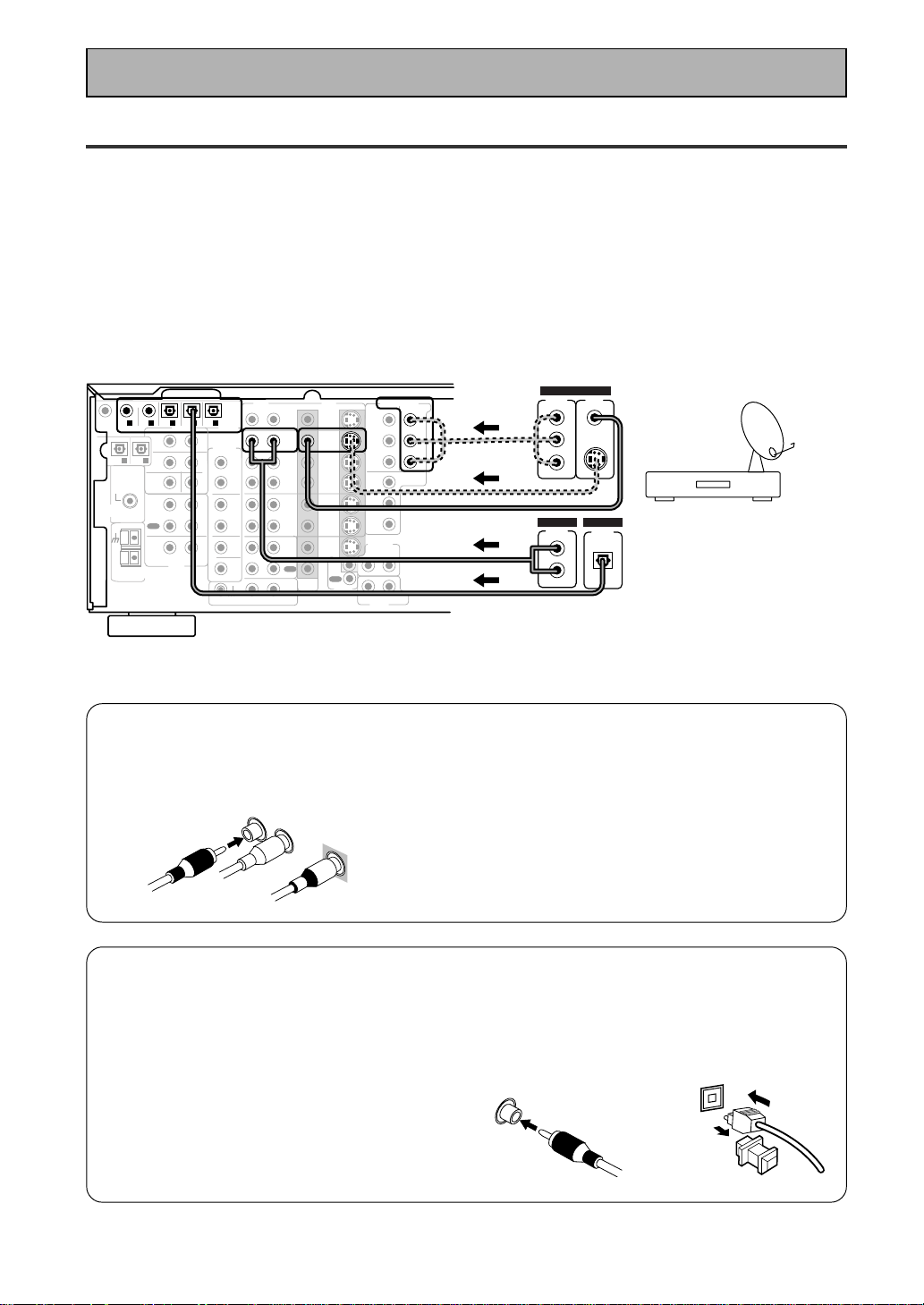
7 Analog audio/video cords
Use audio/video cords (not supplied) to
connect the video components and a video
cord to connect the monitor TV.
Connect red plugs to R (right), white plugs to
L (left), and the yellow plugs to VIDEO.
Be sure to insert completely.
7 Digital audio coaxial cords/
Optical cables
Commercially available digital audio coaxial
cords (standard video cords can also be
used) or optical cables (not supplied) are
used to connect digital components to this
receiver.
When you use optical digital input or output
terminals, pull off the caps and insert the
plugs. Be sure to insert completely.
Digital audio coaxial
cord
(or standard video
cord)
Optical cable
L
R
VIDEO
Satellite TV Components
Connect your satellite TV components to the jacks as shown below. Hook up the video signal with either
component video, S-video, or composite video cords (the quality descends in this order) but remember, the
video component you are watching and your TV must be hooked up with same type of video cord or you won't
be able to see the picture. For the audio signal, order to use digital soundtracks (sometimes broadcast over
digital satellite TV) you must hook up a digital input. Use either a coaxial or optical cables, it doesn't matter
which (you don't need to use both). It's also a good idea to hook up your audio with analog cables (see below).
This connection is called STEREO AUDIO OUT in the diagram.
Before making or changing the connections, switch off the power and disconnect the power cord from the AC
outlet.
*The arrows indicate the direction of the TV signal.
17
En
PREPARATION
CD
IN
SURR-
OUND
SUB
WOOFER
CENTER
FRONT
MULTI CH IN
SURR-
OUND
RL
R
L
R
L
R
L
R
L (Single)
R
R
L
L
R
L
R
L
FRONT
AUDIO
PRE OUT
CENTER
COMPONENT VIDEO
DVD/LD
IN
TV/SAT
IN
Y
P
B
P
R
MONITOR
OUT
MONITOR
OUT 1
MONITOR
OUT 2
P
B
P
R
Y
MULTI CH IN
SURROUND
BACK
SURROUND
BACK
PRE OUT
DVD /
LD
IN
S VIDEOVIDEO
VIDEOAUDIO
IN
TV /
SAT
IN
IN
OUT
IN
VCR1 /
DVR
OUT
IN
OUT
IN
VCR2
OUT
IN
CONTROL
IN
OUT
MD /
TAPE1/
CD-R
PLAY
REC
TAPE2
MONITOR
PLAY
REC
PCM/
2
/
DTS/
MPEG
DIGITAL
IN
5
IN
4
IN
3
2
RF IN
(AC-3)
IN
2
IN
1
IN
PHONO
FM UNBAL
75‰
FM
ANTENNA
AM LOOP
ANTENNA
OUTOUT
21
TV/monitor
COMPO-
NENT
VIDEO
L
VIDEO IN
S-VIDEO
Y
P
B
P
R
SUB
WOOFER
CD
IN
SURR-
OUND
SUB
WOOFER
CENTER
FRONT
MULTI CH IN
SURR-
OUND
RL
R
L
R
L
R
L
R
L (Single)
R
R
L
L
R
L
R
L
FRONT
AUDIO
PRE OUT
CENTER
COMPONENT VIDEO
DVD/LD
IN
TV/SAT
IN
Y
P
B
P
R
MONITOR
OUT
MONITOR
OUT 1
MONITOR
OUT 2
P
B
P
R
Y
MULTI CH IN
SURROUND
BACK
SURROUND
BACK
PRE OUT
DVD /
LD
IN
S VIDEOVIDEO
VIDEOAUDIO
IN
TV /
SAT
IN
IN
OUT
IN
VCR1 /
DVR
OUT
IN
OUT
IN
VCR2
OUT
IN
CONTROL
IN
OUT
MD /
TAPE1/
CD-R
PLAY
REC
TAPE2
MONITOR
PLAY
REC
PCM/
2
/
DTS/
MPEG
DIGITAL
IN
5
IN
4
IN
3
2
RF IN
(AC-3)
IN
2
IN
1
IN
PHONO
FM UNBAL
75‰
FM
ANTENNA
AM LOOP
ANTENNA
OUTOUT
21
SUB
WOOFER
Components equipped with
7.1 (5.1) channel analog output jack
SUB
WOOFER
SURR-
OUND BACK
L
R
CENTER
SURR-
OUND
L
R
FRONT
L
R
ANALOG
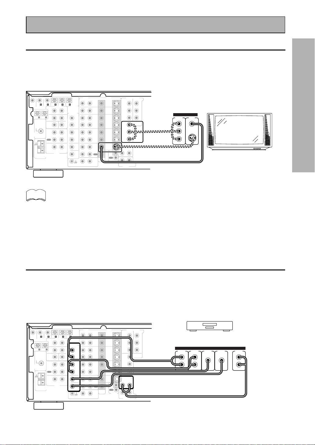
Connecting Your Equipment
TV
Connect your TV to the jacks as shown below. Hook up the signal with either component video, S-video, or
composite video cords (the quality descends in this order) but remember, the video component you are
watching and your TV must be hooked up with same type of video cord or you won't be able to see the picture.
Before making or changing the connections, switch off the power and disconnect the power cord from the AC
outlet.
The COMPONENT VIDEO OUT jack can be used to get a TV picture but it doesn't show this
receiver's on screen display (OSD).
If you use S video cords to hook up a component the OSDs from the receiver will only be able
to be seen on the S video out terminals.
Multi Channel Input (External Decoder)
In some cases you may want to have your source material (DVD, etc) decoded externally. If you find you need a
multi channel external decoder hook one up as shown below, but for most people this component is
unnecessary (For more on this see p.52).
Before making or changing the connections, switch off the power and disconnect the power cord from
the AC outlet.
memo
18
En
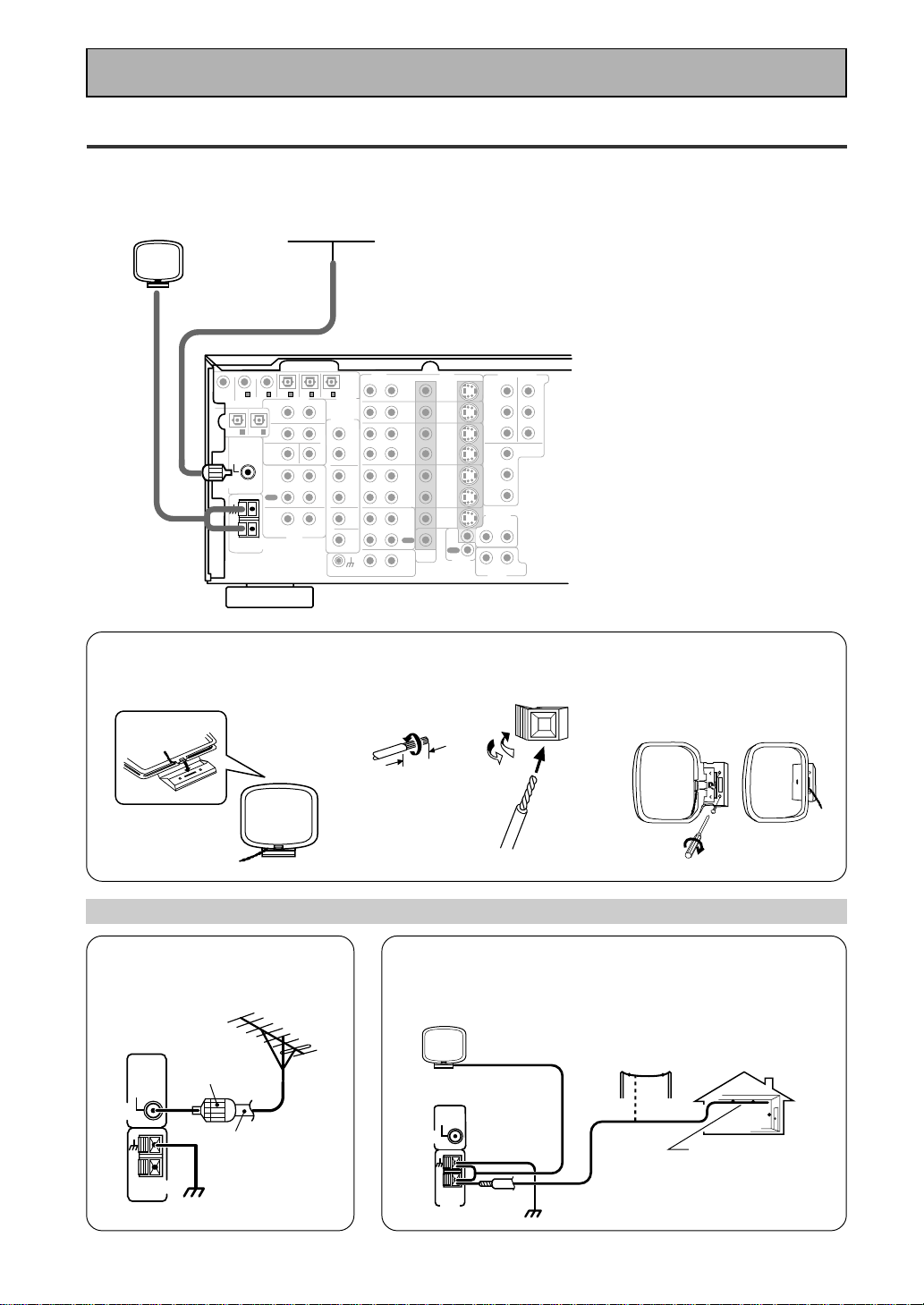
Connecting the Radio Antennas
Connect the supplied FM wire antenna and the AM loop antenna to the antenna terminals as shown below.
These antennas should provide adequate reception quality in most cases, but connecting outdoor antennas
should noticeably improve sound quality.
CD
IN
SURR-
OUND
SUB
WOOFER
CENTER
FRONT
MULTI CH IN
SURR-
OUND
RL
R
L
R
L
R
L
R
L (Single)
R
R
L
L
R
L
R
L
FRONT
AUDIO
PRE OUT
CENTER
COMPONENT VIDEO
DVD/LD
IN
TV/SAT
IN
Y
P
B
P
R
MONITOR
OUT
MONITOR
OUT 1
MONITOR
OUT 2
P
B
P
R
Y
MULTI CH IN
SURROUND
BACK
SURROUND
BACK
PRE OUT
DVD /
LD
IN
S VIDEOVIDEO
VIDEOAUDIO
IN
TV /
SAT
IN
IN
OUT
IN
VCR1 /
DVR
OUT
IN
OUT
IN
VCR2
OUT
IN
CONTROL
IN
OUT
MD /
TAPE1/
CD-R
PLAY
REC
TAPE2
MONITOR
PLAY
REC
PCM/
2
/
DTS/
MPEG
DIGITAL
IN
5
IN
4
IN
3
2
RF IN
(AC-3)
IN
2
IN
1
IN
PHONO
FM UNBAL
75‰
FM
ANTENNA
AM LOOP
ANTENNA
OUTOUT
21
SUB
WOOFER
FM wire antenna
AM loop antenna
7 AM loop antenna
1 Assemble the antenna. 2 Twist exposed wire strands
together and insert.
3 Attach to a wall, etc. (if
desired) and face toward the
direction providing the best
reception.
Using external antennas
7 To improve FM reception
Connect an external FM antenna.
7 To improve AM reception
Connect a 5–6 meter length of vinyl-coated wire to the AM
antenna terminal in addition to the supplied AM loop antenna.
For the best possible reception, suspend horizontally outdoors.
10 mm
FM
ANTENNA
FM UNBAL
75‰
AM LOOP
ANTENNA
75 Ω coaxial
cable
PAL
connector
ground
AM LOOP
ANTENNA
Indoor antenna
(Vinyl-coated
wire)
ground
Outdoor antenna
5–6 m
FM
ANTENNA
FM UNBAL
75‰
Connecting Your Equipment

19
En
PREPARATION
SPEAKERS
A
FRONT
CENTER
SURROUND
FRONT
B
SUB
WOOFER
CD
IN
SURR-
OUND
SUB
WOOFER
CENTER
FRONT
MULTI CH IN
SURR-
OUND
RL
R
L
R
L
R
RL R
R
L
L
L
R
L (Single)
R
R
L
L
R
L
R
L
FRONT
AUDIO
PRE OUT
CENTER
COMPONENT VIDEO
DVD/LD
IN
TV/SAT
IN
Y
P
B
P
R
MONITOR
OUT
MONITOR
OUT 1
MONITOR
OUT 2
P
B
P
R
Y
MULTI CH IN
SURROUND
BACK
SURROUND
BACK
PRE OUT
DVD /
LD
IN
S VIDEOVIDEO
VIDEOAUDIO
IN
TV /
SAT
IN
IN
OUT
IN
VCR1 /
DVR
OUT
IN
OUT
IN
VCR2
OUT
IN
CONTROL
IN
OUT
MD /
TAPE1/
CD-R
PLAY
REC
TAPE2
MONITOR
PLAY
REC
PCM/
2
/
DTS/
MPEG
DIGITAL
IN
5
IN
4
IN
3
2
RF IN
(AC-3)
IN
2
IN
1
IN
PHONO
FM UNBAL
75‰
FM
ANTENNA
AM LOOP
ANTENNA
OUTOUT
21
Surround
speaker
(Right)
Surround back
speaker (Right)
Surround back
speaker (Left)
INPUT
Powered
sub-woofer
Surround
speaker
(Left)
Front
speaker (A)
(Left)
Front
speaker (A)
(Right)
TV/monitor
Center
speaker
Additional Amplifier (See p.21)
memo
Connecting Your Equipment
Speakers
A full complement of eight speakers is shown here but, naturally, everyone's home set up will vary. Simply connect
the speakers you have in the manner described below. The receiver will work with just two stereo speakers (called
"front" speakers in the diagram) but the receiver is designed to be used with at least three speakers.
One of the latest features of home theater is the use of SURROUND BACK speakers. These speakers add even
greater realism in movie sound effects and new discs with soundtracks in Dolby Digital or DTS incorporates these
channels. In order to be able to use these channels you must hook your SURROUND BACK speakers up to an
external amplifier and then connect that to the VSX-909RDS/909RDS-G, as shown in the diagram below. If you only
have one SURROUND BACK speaker hook it up to the SURROUND BACK L (SINGLE) terminal on the back of the
receiver.
In general, make sure you connect the speaker on the right to the right terminal and the speaker on the left to the
left terminal. Also make sure the positive and negative (+/–) terminals on the receiver match those on the speakers.
Before making or changing the connections, switch off the power and disconnect the power cord from the AC
outlet.
The receiver has two speaker systems, A & B. A is the main system supporting the full complement of surround
sound speakers. If you switch on both A & B speaker systems, only front speakers and the subwoofer will be
audible. No sound will come from the center or surround speakers but multi channel sources will be down-mixed
to the active speakers so no sound will be lost. Similarly, if you choose just the B system you‘ll only hear the
front speakers connected to the B system and multi channel sources will be down-mixed to these two speakers.
Please use speakers with a nominal impedance rated 6Ω-16Ω.
7 Speaker terminals
1 Twist exposed wire
strands together.
2 Loosen speaker terminal
and insert exposed wire.
3 Tighten
terminal.
10mm
20
En
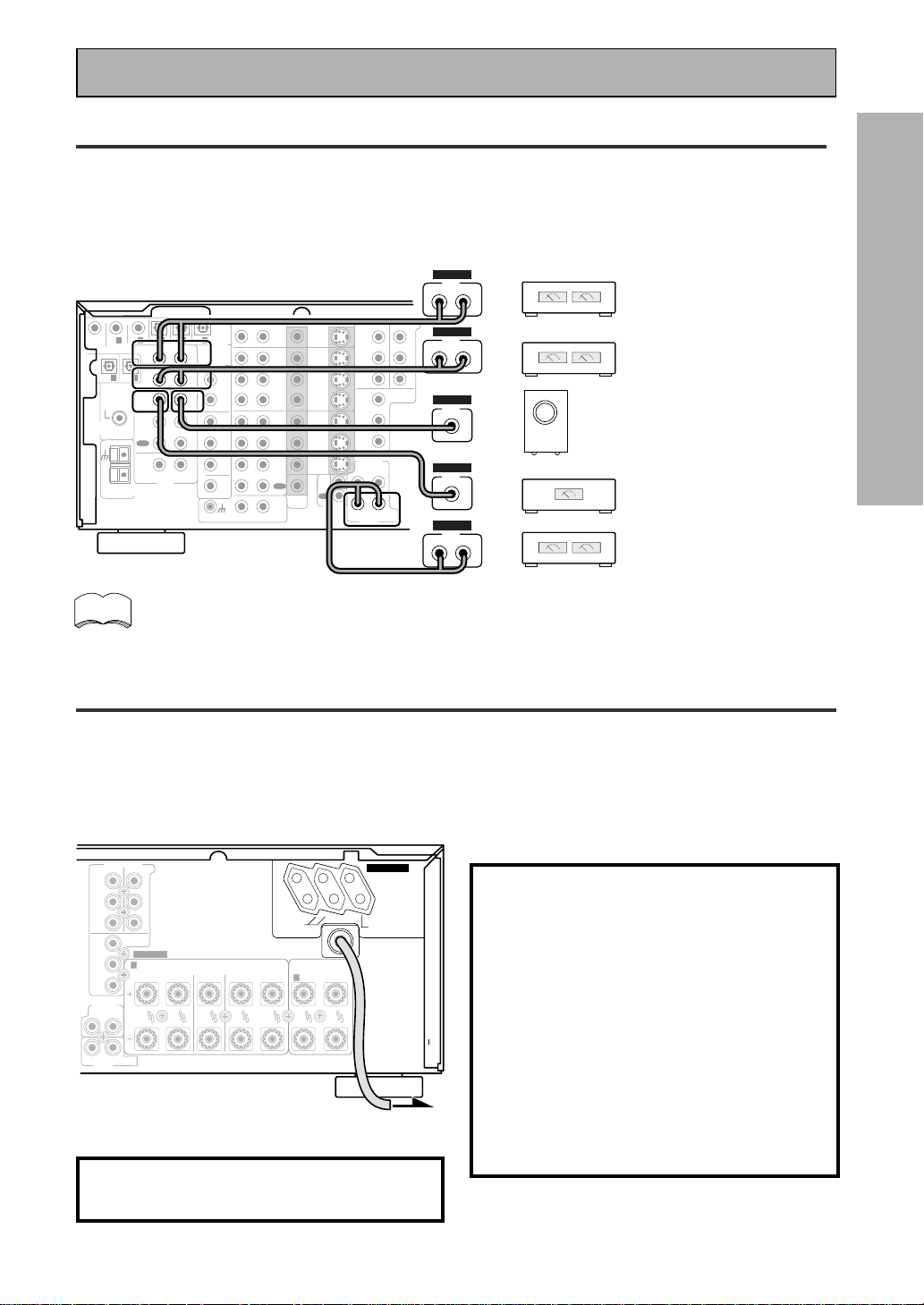
Placing Your Speakers
Proper speaker placement is essential to realize the best sound from your system. The diagram and tips given
here are just a rough guide; be sure to read the instructions that come with your speakers.
• Install the left and right front speakers at equal distances from the TV.
•
When installing speakers near the TV, we recommend using magnetically shielded speakers to prevent
possible interference such as distortion in the color of the TV screen. If you do not have magnetically
shielded speakers and notice discoloration of the TV screen, place the speakers farther away from the TV.
• Install the center speaker above or below the TV so that the sound of the center channel is localized at
the TV screen.
CAUTION:
When installing the center speaker on top of the TV, be sure to secure it with tape or some other
suitable means. Otherwise, the speaker may fall from the TV due to external shocks such as
earthquakes, and it may lead to endangering those nearby or damaging the speaker.
• If possible, install the surround speakers slightly above ear level.
• It may be difficult to obtain a cohesive surround effect if the surround speakers are installed farther
away from the listening position than the front and center speakers.
Speaker placement
If you have a multiple speaker arrangement the placement of the speakers is extremely important. To achieve
the best possible surround sound, install your speakers as shown below. Make sure all speakers are installed
securely to prevent accidents and improve sound quality. Be sure to consult your speaker manuals for the best
placement of the speakers. Some speakers are designed to be floor-standing but others benefit greatly from
speakers stands which raise them off the floor.
memo
Surround
Left
Surround Back
Left
Surround
Right
Surround Back
Right
Listening
Position
Front
Left
Front
RightCenter
Sub
Woofer
Connecting Your Equipment
Speaker impedance
You can change the speaker impedance to suit the kind of speakers you have in your home system. We
recommend, however, using speakers with an impedance of 8 Ω-16 Ω (the default setting). If you are using 6 Ω
−less than 8 Ω impedance speakers, you need to change the impedance setting.
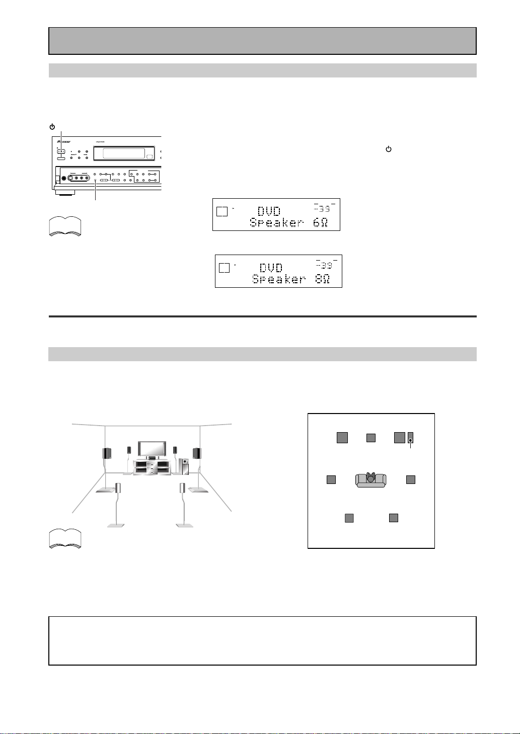
Before operating the receiver, be sure to press the main power button
on the front panel to turn the power ON (_).
First turn the receiver off, then press the STANDBY/ON
button while holding down the SPEAKERS button.
Choose the impedance setting by pressing the SPEAKERS button
again. You can choose the 8Ω-16Ω setting or the 6Ω-8Ω setting.
To check which impedance setting
to hold down the SPEAKERS button
for 2-3 seconds. You'll get a display
like these telling you the speaker
impedance setting.
(This display indicates a 6Ω-
less than 8Ω impedance
setting.)
(This display indicates an 8Ω-
16Ω impedance setting.)
memo
dB
SIGNAL
SELECT
ANALOG
SP
A
VOLUME
dB
SIGNAL
SELECT
ANALOG
SP
A
VOLUME
STANDBY/ON
DSP
MODE
THX CINEMA ADVANCED STANDARD
STANDBY
AUDIO/VIDEO MULTI-CHANNEL RECEIVER
STEREO/
DIRECT
/DTS/MPEG
PHONES
S-VIDEO VIDEO
MULTI CH
INPUT
SIGNAL
SELECT
RF ATT CLASS
TUNER CONTROL
BAND TUNING
STATION
F
DIM
M
E
O
MO
TAPE 2
MONITOR
VIDEO
SELECT
TONE
CHANNEL
SELECT
LOUDNESS
DIGITAL
NR
-
+
-
+
SPEAKERS
-
TREBLE +
-
BASS +
L AUDIO R
VIDEO INPUT
CHARACTER/
SEARCH
MEMORY
— OFF _ ON
STANDBY/ON
SPEAKERS
21
En
PREPARATION
CD
IN
SURR-
OUND
SUB
WOOFER
CENTER
FRONT
MULTI CH IN
SURR-
OUND
RL
R
L
R
L
R
L
R
L (Single)
R
R
L
L
R
L
R
L
FRONT
AUDIO
PRE OUT
CENTER
COMPONENT VIDEO
DVD/LD
IN
TV/SAT
IN
Y
P
B
P
R
MONITOR
OUT
MONITOR
OUT 1
MONITOR
OUT 2
P
B
P
R
Y
MULTI CH IN
SURROUND
BACK
SURROUND
BACK
PRE OUT
DVD /
LD
IN
S VIDEOVIDEO
VIDEOAUDIO
IN
TV /
SAT
IN
IN
OUT
IN
VCR1 /
DVR
OUT
IN
OUT
IN
VCR2
OUT
IN
CONTROL
IN
OUT
MD /
TAPE1/
CD-R
PLAY
REC
TAPE2
MONITOR
PLAY
REC
PCM/
2
/
DTS/
MPEG
DIGITAL
IN
5
IN
4
IN
3
2
RF IN
(AC-3)
IN
2
IN
1
IN
PHONO
FM UNBAL
75‰
FM
ANTENNA
AM LOOP
ANTENNA
OUTOUT
21
Surround channel amplifier
Front channel amplifier
Center channel amplifier (mono)
Surround back channel amplifier
Powered subwoofer
SUB
WOOFER
INPUT
RL
ANALOG
INPUT
RL
ANALOG
INPUT
RL
ANALOG
INPUT
ANALOG
INPUT
ANALOG
R
A
LRLRL
FRONT
CENTER
SURROUND
FRONT
B
SPEAKERS
COMPONENT VIDEO
DVD/LD
IN
TV/SAT
IN
MONITOR
OUT
Y
P
B
P
R
P
B
P
R
Y
RL
L(Single)R
MULTI CH IN
SURROUND
BACK
SURROUND
BACK
PRE OUT
UNSWITCHED
100W MAX
SWITCHED
TOTAL 100W MAX
AC OUTLETS
Connecting Your Equipment
The illustration is not applicable to the U.K. model.
Connecting Additional Amplifiers
To hook up surround back speakers you need to use an additional amplifier. Other than for that purpose this
receiver has more than sufficient power for any home use, but it is possible to add additional amplifiers to
every channel of your system. Make the connections shown below to add amplifiers to power your speakers.
Before making or changing the connections, switch off the power and disconnect the power cord from the AC
outlet.
You can use the additional amplifier on the surround back channels for a single speaker as well. In
this case plug the amplifier into the L (SINGLE) terminal only.
We suggest using a Pioneer M-10X, A-509R amplifier as your additional amp.
memo
Plugging In (Except for the U.K. model)
Up to three components can be powered from this receiver. Two of the outlets are switched, which means that
power is switched on and off with the receiver. The third is unswitched, which means that power is delivered so
long as the receiver is plugged in.
Before making or changing the connections, switch off the power and disconnect the power cord from the AC
outlet.
After connecting all your components, plug the receiver's power cord into a standard wall power outlet.
Caution!
Power consumption of any equipment con-
nected to the switched power outlets should
not exceed 100W (0.8A).
Power consumption of any equipment con-
nected to the unswitched power outlet should
not exceed 100W (0.8A).
To avoid overheating, fire risk and possible
malfunction, do not connect high-wattage
appliances such as heaters, irons, monitors or
TV sets to this units AC outlets.
Disconnect the receiver from the power outlet
when it's not in regular use, for example,
when on vacation.
Caution!
Do not connect a monitor or TV to this unit's AC
OUTLETS.
22
En
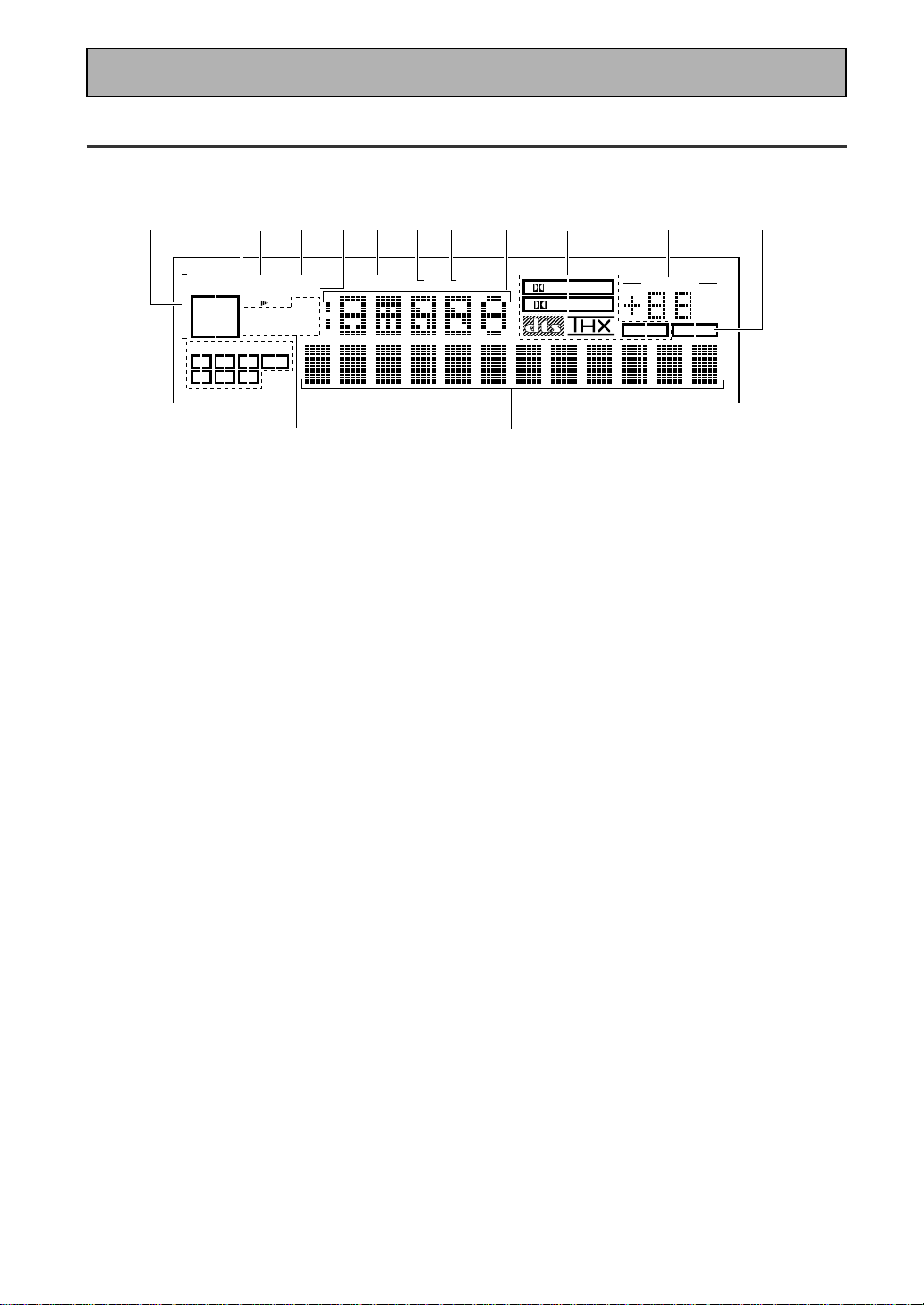
Display
All the display information is explained and/or referenced here.
4 Speaker indicators
Light to indicate the current speaker system, A
and/or B.
5 LOUDNESS indicator (See p.50)
Lights when the LOUDNESS mode is on.
6 H.P (headphones)
Lights when headphones are connected to the
PHONES jack (speakers systems A and B both
turn off automatically).
7 MIDNIGHT indicator (See p.50)
Lights when the MIDNIGHT LISTENING mode
is on.
8 DSP indicator (See p.42-46,48)
Light when a DSP or Advanced Theater modes
are selected.
9 STEREO indicator
Lights when a STEREO mode is selected.
10 Function indicator
Displays the function.
11 2/dts/MPEG mode indicators
2 DIGITAL : When the 2 /dts/MPEG mode on
the receiver is on, this indicator lights to indicate
playback of a Dolby Digital signal. However,
2
PRO LOGIC lights during 2 channel playback of
Dolby Digital.
2 PRO LOGIC : When the 2 /dts/MPEG mode
on the receiver is on, this indicator lights during 2
channel playback.
dts : Lights when DTS signals are input.
THX: Lights when the HOME THX CINEMA mode
is selected.
MPEG: Lights when MPEG signals are input.
12
MASTER VOLUME indication
Displays current volume level.
1 SIGNAL SELECT indicators
Light to indicate the input signal you selected.
ANALOG : Lights when analog signals are
assigned.
DIGITAL : Lights when digital audio signals are
selected.
AC-3 RF : Lights when AC-3 RF signals are
assigned.
AUTO : Lights when the receiver is set to select
the input signal automatically.
2
Program Format indicators
AC-3 : Lights when a source with Dolby Digital
signals is played.
DTS: Lights when a source with DTS audio signals
is played.
MPEG: Lights when a source with MPEG audio
signals is played.
For Dolby Digital or DTS sources, these
indicators change according to which channels
are active in the source. When all three LS (left
surround), S (surround) and RS (right surround)
light at the same time it means a Source with
Surround EX or DTS-ES flag is being used.
L – Left front channel.
C – Center channel.
R – Right front channel.
LS – Left surround channel.
S – Surround channel (mono).
RS – Right surround channel.
LFE – Low Frequency Effects channel.
3 Analog level indicators
OVER – When the source signal is analog, this
lights if the signal is in danger of distorting.
Press INPUT ATT on the remote control to
lower the signal level.
ATT – Lights when INPUT ATT is used to
reduce the level of the analog source signal.
DIGITAL
dB
PRO LOGIC
STEREO
DSP
MIDNIGHTLOUDNESSATTSIGNAL
SELECT
OVER
H.P
ANALOG
SP AB
L
C
R
LFE
LS S RS
DIGITAL
AC-3RF
AUTO
TAPE 2
VOLUME
AC-3DTS MPEG
EON
RDS
RF ATT
MPEG
MONO STEREO
TUNED AMFM
1
34
5
6
789
10
11
12
13
14
15
2
Displays & Controls

23
En
PREPARATION
Displays & Controls
13
TAPE 2 indicator
Lights when the TAPE 2 monitor is on.
14
Character display
Displays sound modes, general information.
15
Tuner indicators
MONO: Lights when the tuner is set to receive
FM broadcasts and when selected MPX mode.
STEREO: Lights when a FM stereo broadcast is
received in the auto stereo mode.
TUNED: Lights when a broadcast is received.
AM/FM: Light to indicate the current band (FM or
AM).
EON: Lights when an RDS stations transmitting
the EON data service is being received.
RF ATT: Lights when the RF attenuator is on.
RDS: Lights when RDS broadcast is being
received.
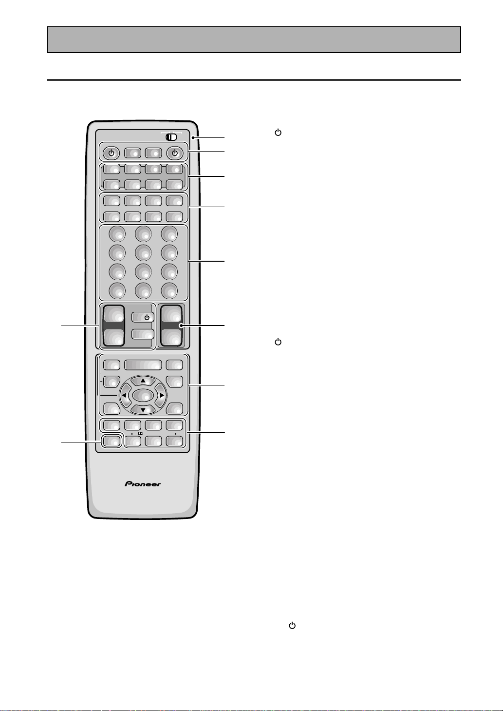
24
En
Remote Control
1 USE/SETUP slide switch
Use to put the remote into receiver SETUP, or
receiver USE mode.
2 SOURCE button
Use to turn on the power of your other
components after you have recalled or taught
the signals to this remote control.
MULTI OPERATION button
Use this button to start the MULTI OPERATION
mode. See page 78-79 for how to program and
use the MULTI OPERATION mode.
SYSTEM OFF button
This button turns off components in two ways.
First, when pressed it will turn off all PIONEER
components. Secondly, any component that
has programmed into the SYSTEM OFF
settings will also be turned off (see p.80).
For example : If you programmed power on for
your TV and VCR, pressing the SYSTEM OFF
button will turn off these components even if
they are not PIONEER products.
RECEIVER button
Press to turn power of the receiver on or to
STANDBY (off).
3 MULTI CONTROL buttons
Use these to select a source and the
corresponding remote operation mode.
For example, pressing TUNER selects the built
in tuner and sets the remote operation to the
tuner functions.
4 Component Control buttons
Use to control specific components, like a CD
player or DVD player, after you have
programmed the remote control to do these
operations (see pages 65–68) and the remote is
put in that operation mode.
5 Number buttons
These buttons can perform a variety of
different functions depending on the remote
operation mode. They are most useful for CD
and tuner operations.
6 TV CONTROL buttons
The following buttons are used to control the
TV only and can be used no matter what
function the remote control is set to.
TV
button – Press to turn the power of the
TV on/off.
TV FUNC button – Press TV FUNC to select
the TV for remote control operation.
TV VOL +/- button – Use to adjust the TV
volume.
Displays & Controls
AV PRE-PROGRAMMED AND LEARNING
REMOTE CONTROL UNIT
/DTS/MPEG
S0URCE
DVD/LD TV/SAT VCR1 VCR2
CD
TV VOL
TV FUNC
MENU
ENTER
STEREO/
DIRECT
DSP
THXLIGHT
MUTE
TV
VOLUME
MD/
TAPE1
TUNER TVCONT
RECEIVER
USE SETUP
MULTI
OPERATION
CLASS MPX
DIRECT ACCESS
CHANNEL
STATION
TUNING
DISPLAY
RF ATT
TV CONTROL
FUNCTION
REMOTE SETUP
SYSTEM SETUP
INPUT
ATT
ADVANCED
MIDNIGHT
MULTI CH
INPUT
STANDARD
DIGITAL
NR
EFFECT/
CH SEL
SIGNAL
SELECT
BAND
SYSTEM
OFF
123
456
789
0
DISC
Î
873
1¡4¢
+
-
+
-
+
-
MULTI CONTROL
++
––
+
–
+10
1
2
3
4
5
76
8
9
10

25
En
PREPARATION
5(+)/∞(–)/2/3/ENTER buttons
Use to operate the on-screen menu on your TV
screen and enter commands when setting up
surround sound, speakers levels & settings,
and other set up features see p.29–41).
Specific use of these buttons is described in
conjunction with the operations they perform.
For more information see each individual
section.
DIGITAL NR button
Press to switch Digital NR on or off. (See page
49)
SIGNAL SELECT button
Press SIGNAL SELECT repeatedly to select one
of the following:
ANALOG – Analog signal.
DIGITAL – Digital signal (DVD/LD, TV/SAT, CD,
MD/TAPE 1/CD-R, VCR 1/DVR, VCR 2, LINE).
AC-3 RF – 2 RF signal (DVD/LD, TV/SAT, VCR
1, VCR 2).
AUTO – This is the default. If there are both
analog, digital, 2 RF input signals, the
receiver automatically selects the best possible
signal.
9 STEREO/DIRECT button (See p.44 & 53)
Switches the receiver into STEREO mode if it
was in a different sound mode (like ADVANCED
THEATER) or toggles between DIRECT and
STEREO mode. For more on STEREO mode
see p.53.
DIRECT playback bypasses the tone controls
and channel level for the most accurate
reproduction of a program source.
DSP button (See p.42-46, 48)
Press repeatedly to select a DSP sound mode.
/DTS/MPEG buttons (See p.42-46)
Press these buttons to put the receiver in the
selected sound mode. For more information on
the sound modes see p.85&86.
MULTI CH INPUT button
Press to switch to MULTI CH IN mode.
MIDNIGHT button (See p.50)
Switches the MIDNIGHT mode on or off.
10 LIGHT button
Press to light the remote control buttons.
7 MASTER VOLUME buttons
Use to raise or lower the volume of the
receiver.
8 INPUT ATT button (when USE mode is
selected)
Use to lower the input level of an analog signal
that is too powerful, thus causing the sound to
distort (the OVERLOAD indicator will light).
REMOTE SETUP button (when SETUP
mode is selected)
Use to customize the remote control functions
and the remote control itself. (See “Setting Up
the Remote Control to Control Other Compo-
nents“ starting on p.65, “Multi Operation“
starting on p.78)
MENU button
Use to get the various menus for your TV or
DVD.
MUTE button
Press to mute or restore the volume.
EFFECT/CH SEL,5(+)/∞(–) (when USE
mode is selected) button (see memo on
p.45)
EFFECT – Use these buttons to increase or
decrease the amount of effect applied in a DSP
or Advanced Theater mode. When the amount
of effect is increased in a DSP/Advanced
Theater mode the characteristics of that mode
become stronger and more noticeable. The
scale ranges from 10-90 with 70 as the default
setting. First turn on the DSP/Advanced
Theater you want (by pressing the DSP/
Advanced Theater button until you get the
mode) and then increase or decrease the
amount of effect.
CH SEL – You may want to adjust the channels
when listening to some sound sources. Use
this button to select the channel you want to
adjust.
SYSTEM SET UP button (when SETUP
mode is selected)
Use to set up the speaker and sound systems.
For more information see “Setting up for
Surround Sound“
starting on p.30.
FUNCTION button
Press to select a source. The button will cycle
through all the possible sources.
Displays & Controls
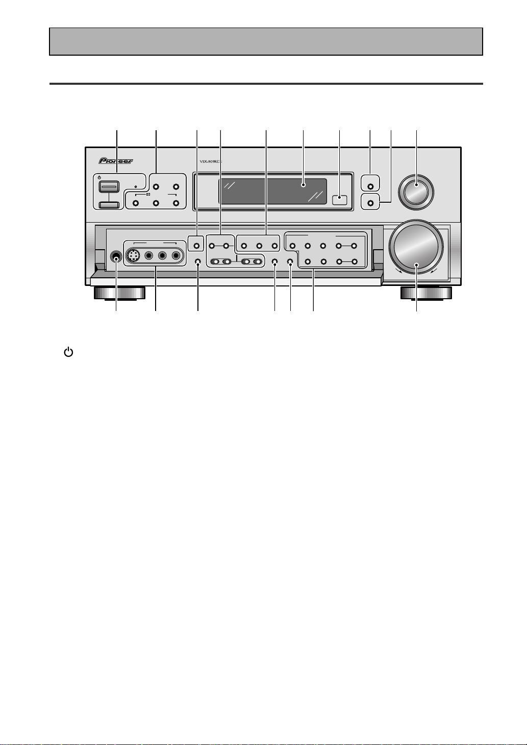
26
En
Front Panel
All the controls on the front panel are explained and/or referenced here. To open the front panel push
gently on the lower third of the panel.
1 STANDBY/ON button
Press to switch the receiver ON or into
STANDBY mode.
STANDBY indicator
Lights when the receiver is in STANDBY mode.
(Please note that this receiver consumes a
small amount of power [1.0 W] in the standby
mode.)
_ ON/ — OFF button
If the button is OFF (—), the power of the
receiver is shut off and the STANDBY/ON
button on the receiver or the remote control do
not function. Pressing the button again will
turn the receiver ON (_) and the receiver
enters the standby mode. In the standby mode,
you can turn on the receiver using the STAND-
BY/ON button on the receiver or the remote
control.
2 DSP MODE button (See p.44 & 45)
Press repeatedly to select a DSP sound mode.
(HALL 1, HALL 2, JAZZ, DANCE, THEATER 1,
or THEATER 2, 5/7 CH STEREO). Use these
modes to produce surround sound from
standard (two channel) stereo sources and
create different listening environments.
STEREO/DIRECT button (See p.44 & 53)
Switches the receiver into STEREO mode if it
was in a different sound mode (like ADVANCED
THEATER) or toggles between DIRECT and
STEREO mode. For more on STEREO mode
see p.44.
DIRECT playback bypasses the tone controls,
DIGITAL NR, LOUDNESS, MIDNIGHT and
channel level for the most accurate reproduc-
tion of a program source.
2/ DTS/ MPEG buttons (See p.42-46,
85, 86)
THX CINEMA – Cycles through the THX
CINEMA, THX SURROUND EX or THX AUTO
sound modes. If you have THX-certified
speaker setup or want to re-create a THX-style
sound environment. It is also appropriate for
Dolby Digital, Dolby Pro Logic, DTS or MPEG
sources. Those with surround back speakers
can use all three THX modes, those without
can only use the THX CINEMA mode.
ADVANCED – Use to select one of the four
Advanced Theater modes. Use to create certain
types of sound environments when listening to
Dolby Digital, Dolby Pro Logic, DTS or MPEG
sources.
STANDARD – Use for pure decoding of multi
channel sources, especially Dolby Digital, Dolby
Pro Logic, DTS or MPEG sources. Each press
toggles between STANDARD and STANDARD
7.1 mode (for use with SURROUND BACK
speakers) and STANDARD auto (the receiver
chooses the appropriate STANDARD mode).
Those with surround back speakers can use all
three STANDARD modes, those without can
only use the STANDARD mode.
STANDBY/ON
— OFF _ ON
DSP
MODE
INPUT
SELECTOR
MASTER
VOLUME
THX CINEMA ADVANCED STANDARD
STANDBY
AUDIO/VIDEO MULTI-CHANNEL RECEIVER
STEREO/
DIRECT
/DTS/MPEG
DOWN UP
PHONES
S-VIDEO VIDEO
MULTI CH
INPUT
SIGNAL
SELECT
RF ATT CLASS
TUNER CONTROL
BAND TUNING
STATION
FL
DIMMER
EON
MODE
TAPE 2
MONITOR
VIDEO
SELECT
TONE
CHANNEL
SELECT
LOUDNESS
DIGITAL
NR
-
+
-
+
SPEAKERS
-
TREBLE +
-
BASS +
L AUDIO R
VIDEO INPUT
CHARACTER/
SEARCH
MEMORY
12 53678109
11 12 13 14 15 16
17
4
Displays & Controls

27
En
PREPARATION
3 MULTI CH INPUT (See p.41, 52)
Use to hook up an external component that can
decode other types of signals and input them
into the VSX-909RDS/909RDS-G.
4 TONE buttons
This button has two functions. Firstly, it
switches between TONE ON and TONE
BYPASS, which bypasses the tone circuitry.
Secondly, you need to press the button before
using the CHANNEL SELECT buttons to adjust
the BASS & TREBLE (cannot be used in THX or
MULTI CH IN modes).
CHANNEL SELECT button
Switches the tone adjust controls between the
FRONT, CENTER, SURROUND and SUR-
ROUND BACK speakers. You can then use the
BASS and TREBLE controls to adjust the
sound.
BASS (–/+) buttons (See p.51)
Use to adjust low frequencies.
TREBLE (–/+) buttons (See p.51)
Use to adjust the high frequencies.
5 LOUDNESS button (See p.50)
Switches the LOUDNESS mode on or off (can
not be used in THX and MULTI CH IN.
DIGITAL NR button (See p.49)
Switches the DIGITAL NR on or off (cannot be
used in THX or MULTI CH IN mode).
SIGNAL SELECT button (See p.48)
Use to select the type of signal being input into
the receiver. Press SIGNAL SELECT repeatedly
to select one of the following:
ANALOG – To select an analog signal.
DIGITAL – To select a optical or coaxial digital
signal.
AC-3 RF – To select an 2 RF signal.
AUTO – This is the default. If there are analog,
digital and 2 RF signals input, the receiver
automatically selects the 2 RF signal. If there
are analog and digital signals input the digital
will be selected.
6 Display (See page 22)
7 Remote sensor
Point the remote control toward the remote
sensor to operate the receiver.
8 EON MODE button/indicator
Press to select the EON mode in the FM mode
(see “Setting EON” on page 64). The indicator
lights when the EON mode is selected.
9 FL DIMMER button (See p.53)
Use to adjust the brightness of the main
display.
10 INPUT SELECTOR dial
Turn to select a source component.
DVD/LD – DVD player or Laser Disc player.
TV/SAT– TV or satellite tuner.
CD – Compact Disc player.
MD/TAPE1/CD-R – Tape deck, Mini Disc
recorder or CD recorder connected to MD/
TAPE 1/CD-R inputs/outputs.
TUNER – The built-in tuner.
PHONO – Turntable.
VIDEO – Video camera (etc.) connected to the
VIDEO INPUT on the front panel.
VCR1/DVR – Video cassette recorder connect-
ed to VCR1/DVR inputs.
VCR 2 – Video cassette recorder or other
component connected to VCR 2 inputs.
11 PHONES jack
Connect headphones for private listening (no
sound will be heard through the speakers).
12 VIDEO INPUT jacks (See p.15)
S-VIDEO: Video input for connecting a video
camera (etc.), that has an S-Video out.
VIDEO / AUDIO (L/R): Video input for connect-
ing a video camera, etc. that has standard
video/audio outputs.
13
SPEAKERS (A/B) button
Use to select the speaker system. A is the
primary setting. It plays all speakers hooked up
to the A system. A & B setting only plays the
front speakers of both the A & B systems and
the subwoofer. Multi channel sources will be
down-mixed to these speakers so no sound will
be lost. B setting only plays the front speakers
connected to the B system and multi channel
sources will be down-mixed to these two
speakers. The button cycles through the
speaker systems as follows: A]B]A&B]off.
14
VIDEO SELECT button
Switches the receiver between the various
types of video input.
15 TAPE 2 MONITOR button (See p.76)
Selects the tape deck (MD recorder, etc.)
connected to the TAPE 2 MONITOR inputs/
outputs. Allows monitoring of a recording as
it's being made.
Displays & Controls

28
En
Displays & Controls
16
TUNER CONTROL buttons (See p.55-63)
CLASS button – Press repeatedly to switch
the preset station classes.
RF ATT button – Press to turn the RF attenua-
tor on when receiving strong FM signals
(nearby stations) to reduce sound distortion.
Normally, set the RF attenuator to off. This
button does not affect AM reception.
BAND button – Press to select the AM or FM
band.
TUNING –/+ button – Use to manually tune to
radio stations.
CHARACTER/ SEARCH button – Press to select
the character input mode, or initiate an RDS
PTY search (see “Memorizing a broadcast
station name” on p.59 and “Searching for a
program by program type (PTY)“ on p.63).
MEMORY button – Press to start the memori-
zation of a preset station.
STATION –/+ button – Use to choose pro-
grammed radio stations.
17
MASTER VOLUME
Adjusts the overall receiver volume.
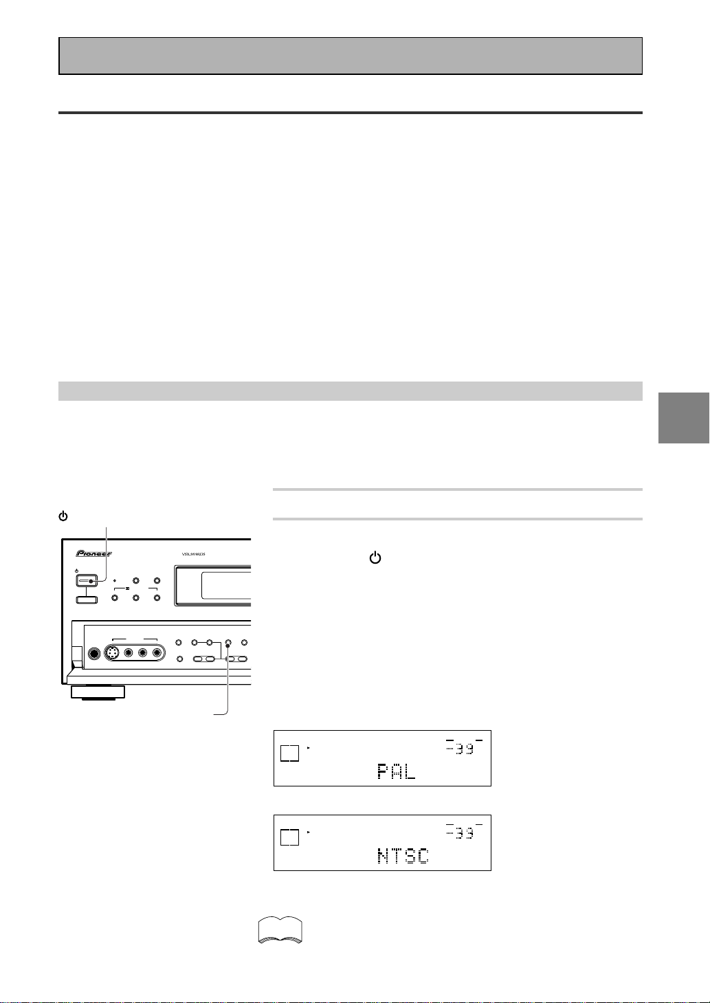
29
En
SET
UP
Switching video system between PAL and NTSC
This receiver is able to use two types of video systems for its OSD (on screen display) and you need to set the
receiver to the type of video system you have, either PAL or NTSC. If you do not match the system on the
receiver with your home system no OSD will appear on your TV. People with multi-system TVs do not need to
worry about changing the setting. If necessary, follow the instructions below to switch the type of video
system.
1 Put the receiver in the STANDBY mode.
2 While holding down the LOUDNESS button,
press the STANDBY/ON button.
The video system type will change depending on the state the
receiver was previously in. The new type, either PAL or NTSC,
will appear in the display. It will be shown for about seven
seconds and then the receiver returns to normal operating
mode.
To change the video system type again repeat steps 1 and 2.
Make sure you press the LOUDNESS button, using others
buttons may change this receiver’s settings.
dB
SIGNAL
SELECT
SP
A
DIGITAL
VOLUME
When a PAL system is selected
dB
SIGNAL
SELECT
SP
A
DIGITAL
VOLUME
When a NTSC system is selected
When using the PAL setting the OSD does not get displayed
in color.
On Screen Display
There are a number of possible ways to hook up the receiver to your video components, like a DVD player, and
hook up to your receiver to your TV, but some of them will not allow you to use the on-screen display of this
unit. To avoid this, you simply need to keep the following rules:
1 Always use the same type of video cords to hook up your video components to the receiver as you use to
hook up the receiver to your TV. For example, if you use composite video cords to hook up your DVD player
to the receiver, use composite video cords to hook up the receiver to your TV. If you use S video cords to
hook up your DVD player and the receiver, use S video cords to hook up the receiver to your TV.
2 Always make sure your TV is set to the appropriate input channel (for example, video 1). Your TV may have a
number of input channels and if you do not select the proper one, you will not be able to use this receiver’s
on-screen display, or, in fact see any picture from this receiver at all. If you are unsure how to choose an
input channel for your TV, refer to the manual which came with your TV.
You might, for example, use both composite and S video cords to hook up your video components with this
receiver and then use composite video cords to hook up this receiver to your TV. This arrangement would still
NOT let you see the on-screen displays from this receiver on your TV. The best idea is just to use one type of
video cords for all your video component and TV hook ups.
STANDBY/ON
DSP
MODE
THX CINEMA ADVANCED STANDARD
STANDBY
AUDIO/VIDEO MULTI-CHANNEL RECEIVER
STEREO/
DIRECT
/DTS/MPEG
PHONES
S-VIDEO VIDEO
MULTI CH
INPUT
TONE
CHANNEL
SELECT
LOUDNESS
DIGITAL
NR
SPEAKERS
-
TREBLE +
-
BASS +
L AUDIO R
VIDEO INPUT
— OFF _ ON
STANDBY/ON
LOUDNESS
memo
Initial Set Up
 Loading...