


AUDIO/VIDEO
MULTI-CHANNEL RECEIVER
VSX-709RDS VSX-609RDS
Operating Instructions
IMPORTANT 1
The lightning flash with arrowhead symbol, within an equilateral triangle, is intended to alert the user to the presence of uninsulated "dangerous voltage" within the product's enclosure that may be of sufficient magnitude to constitute a risk of electric shock to persons.
CAUTION
RISK OF ELECTRIC SHOCK
DO NOT OPEN
CAUTION:
TO PREVENT THE RISK OF ELECTRIC SHOCK, DO NOT REMOVE COVER (OR BACK). NO USERSERVICEABLE PARTS INSIDE. REFER SERVICING TO QUALIFIED SERVICE PERSONNEL.
The exclamation point within an equilateral triangle is intended to alert the user to the presence of important operating and maintenance (servicing) instructions in the literature accompanying the appliance.
IMPORTANT 2 |
The cut-off plug should be disposed of and must not be |
Do not connect either wire to the earth terminal of a |
||
inserted into any 13 amp socket as this can result in electric |
three - pin plug. |
|||
shock. The plug or adaptor or the distribution panel should |
|
|||
FOR USE IN THE UNITED |
be provided with 5 amp fuse. As the colours of the wires in |
NOTE |
||
the mains lead of this appliance may not correspond with |
After replacing or changing a fuse, the fuse cover in the |
|||
KINGDOM |
|
|||
|
coloured markings identifying the terminals in your plug, |
plug must be replaced with a fuse cover which corre- |
||
The wires in this mains lead are coloured in |
proceed as follows : |
sponds to the colour of the insert in the base of the plug |
||
accordance with the following code : |
The wire which is coloured blue must be connected to the |
or the word that is embossed on the base of the plug, and |
||
Blue |
: Neutral |
terminal which is marked with the letter N or coloured black. |
the appliance must not be used without a fuse cover. If |
|
Brown |
: Live |
The wire which is coloured brown must be connected |
lost replacement fuse covers can be obtained from: |
|
If the plug provided is unsuitable for your socket |
to the terminal which is marked with the letter L or coloured |
your dealer. |
||
outlets, the plug must be cut off and a suitable plug |
red. |
Only 5 A fuses approved by B.S.I. or A.S.T.A. to B.S. |
||
fitted. |
|
|
1362 should be used. |
|
Thank you for buying this Pioneer product. Please read through these operating instructions so you will know how to operate your model properly. After you have finished reading the instructions, put them away in a safe place for future reference.
In some countries or regions, the shape of the power plug and power outlet may sometimes differ from that shown in the explanatory drawings. However, the method of connecting and operating the unit is the same.
WARNING:TOPREVENTFIREORSHOCKHAZARD, DO NOT EXPOSE THIS APPLIANCE TO RAIN OR MOISTURE.
This product complies with the Low Voltage Directive (73/23/EEC), EMC Directives (89/336/EEC, 92/31/EEC) and CE Marking Directive (93/68/EEC).
THE POWER SWITCH IS SECONDARY CONNECTED AND THEREFORE DOES NOT SEPARATE THE UNIT FROM MAINS POWER IN STANDBY POSITION.
Power cord CAUTION!
Handle the power cord by the plug. Do not pull out the plug by tugging the cord and never touch the power cord when your hands are wet as this could cause a short circuit or electric shock. Do not place the unit, a piece of furniture, etc., on the power cord, or pinch the cord. Never make a knot in the cord or tie it with other cords. The power cords should be routed such that they are not likely to be stepped on. A damaged power cord can cause a fire or give you an electrical shock. Check the power cord once in a while. When you find it damaged, ask your nearest PIONEER authorized service center or your dealer for a replacement.
Maintenance of External Surfaces
•Use a polishing cloth or dry cloth to wipe off dust and dirt.
•When the surfaces are dirty, wipe with a soft cloth dipped in some neutral cleanser diluted five or six times with water, and wrung out well, and then wipe again with a dry cloth. Do not use furniture wax or cleansers.
•Never use thinners, benzine, insecticide sprays or other chemicals on or near this unit, since these will corrode the surfaces.
2
En
Table of Contents |
|
Features........................................................................................ |
4 |
Introductory Information ............................................................ |
5 |
Checking the Supplied Accessories .............................................................................. |
5 |
Using this Manual .......................................................................................................... |
5 |
Installing the Receiver ................................................................................................... |
5 |
When Making Cable Connections ................................................................................. |
5 |
Preparing the Remote Control ....................................................................................... |
6 |
Connecting Your System ............................................................ |
7 |
Audio Components ........................................................................................................ |
7 |
Video Components ........................................................................................................ |
8 |
Digital Components ....................................................................................................... |
9 |
DVD 5.1 Channel Components .................................................................................... |
11 |
Antennas ..................................................................................................................... |
12 |
Speakers ...................................................................................................................... |
13 |
Preparations............................................................................... |
15 |
Setting Up for Surround Sound ................................................................................... |
15 |
Setting the Volume Level of Each Channel ................................................................. |
21 |
Setting Up the Remote Control ................................................................................... |
22 |
Clearing One of the Remote Control Settings (VSX-709RDS) ....................................... |
25 |
Clearing All the Remote Control Settings .................................................................... |
25 |
Direct Function ............................................................................................................ |
26 |
Programming a Different Component into a MULTI CONTROL Button (VSX-709RDS) . 27 |
|
Checking Preset Code (VSX-709RDS) .......................................................................... |
27 |
Displays & Controls................................................................... |
28 |
Front Panel .................................................................................................................. |
28 |
Remote Control (VSX-709RDS) ................................................................................... |
30 |
Remote Control (VSX-609RDS) ................................................................................... |
32 |
Display ......................................................................................................................... |
34 |
Sound Modes ............................................................................ |
35 |
Learning About the Sound Modes ............................................................................... |
35 |
Switching ANALOG/DIGITAL Signal Input ................................................................... |
36 |
Playing a Source .......................................................................................................... |
37 |
Playing Sources with Dolby Digital or DTS Sound ....................................................... |
38 |
Selecting a Sound Mode ............................................................................................. |
39 |
Using in MIDNIGHT Listening Mode ........................................................................... |
41 |
Using the Tuner ......................................................................... |
42 |
Finding a Station .......................................................................................................... |
42 |
Tuning Directly to a Station .......................................................................................... |
43 |
Memorizing Stations .................................................................................................... |
44 |
Naming Memorized Stations ....................................................................................... |
45 |
Recalling Memorized Stations ..................................................................................... |
46 |
An Introduction to RDS & EON ................................................................................... |
47 |
Searching for RDS Programmes .................................................................................. |
49 |
Setting EON ................................................................................................................. |
50 |
Making a Recording .................................................................. |
51 |
Making an Audio or a Video Recording ........................................................................ |
51 |
Controlling the Rest of Your System ....................................... |
52 |
CD/MD/CD-R/VCR/LD Player Controls ......................................................................... |
52 |
Cassette Deck Controls ............................................................................................... |
53 |
DVD Player/DVR Controls ............................................................................................ |
54 |
Cable TV/Satellite TV/TV Controls ................................................................................ |
55 |
Additional Information.............................................................. |
56 |
Troubleshooting ........................................................................................................... |
56 |
Preset Code List for VSX-709RDS ............................................................................... |
58 |
Preset Code List for VSX-609RDS ............................................................................... |
63 |
Specifications .............................................................................................................. |
66 |
up Set
Operation
3
En

Features
Decoding of DTS (Digital Theater Systems)
This is the latest and most widely used digital theater system for cinemas throughout the world. The decoder has been incorporated into this receiver and is able to achieve high sound quality as well as produce dynamic surround sound effects.
Manufactured under license from Digital Theater Systems, Inc. US Pat. No. 5,451,942 and other worldwide patents issues and pending. “DTS” and “DTS Digital Surround” are trademarks of Digital Theater Systems, Inc. © 1996 Digital Theater Systems, Inc. All right reserved.
Decoding of Dolby Digital and Dolby Pro Logic
No need to worry about program formats. When playing Dolby Digital or Dolby Surround software in the 2(Dolby) Surround mode, decoding switches automatically according to the input signal. When connecting a DVD/LD player or LD player using the 2RF output, a commercially available RF demodulator (RFD-1) is required.
Manufactured under license from Dolby Laboratories. “Dolby”, “Pro Logic” and the double-D symbol are trademarks of Dolby Laboratories. Confidential unpublished works.
© 1992 - 1997 Dolby Laboratories. All rights reserved.
RDS (Radio-Data System)
With the RDS system, FM stations can send additional information with their regular programs. For example, the stations send their station name, and information about the type of programs they broadcast, such as news, sports or music. This unit receives three types of RDS information: Radio Text (RT), Programme Service Name (PS), and Programme Type (PTY). When EON is turned on and a function other than the tuner is set, the function will switch to the FM station automatically when Traffic Information or News begins.
Advanced Theater Modes
Four sound modes that enhance DTS and Dolby Surround performance by simulating the environment of a movie theater (DRAMA, ACTION), or the ambience of a concert hall (MUSICAL). With EXPANDED THEATER, you can enjoy Dolby Surround encoded software in simulated Dolby Digital.
DSP Surround Modes
DSP (Digital Signal Processing) surround modes give you the capability of transforming your living room into six different sonic environments when listening to music or movies.
Midnight Listening Mode
Midnight Listening mode allows you to obtain excellent surround sound effects even when listening at low volumes, something that was previously impossible.
DVD 5.1 channel input
A special 5.1 Channel input makes the VSX-709RDS/609RDS fully compatible with Dolby Digital decoders and DVD players with 5.1 channel outputs.
Remote Control of Other Components
The supplied remote control can be used to operate a variety of other components simply by recalling the appropriate preset codes. Only the VSX-709RDS has a learning function in the remote control which can be used to teach it new commands.
The Energy-saving Design
This unit is designed to use less than 1 W of energy when this unit is in standby mode.
4
En
Introductory Information
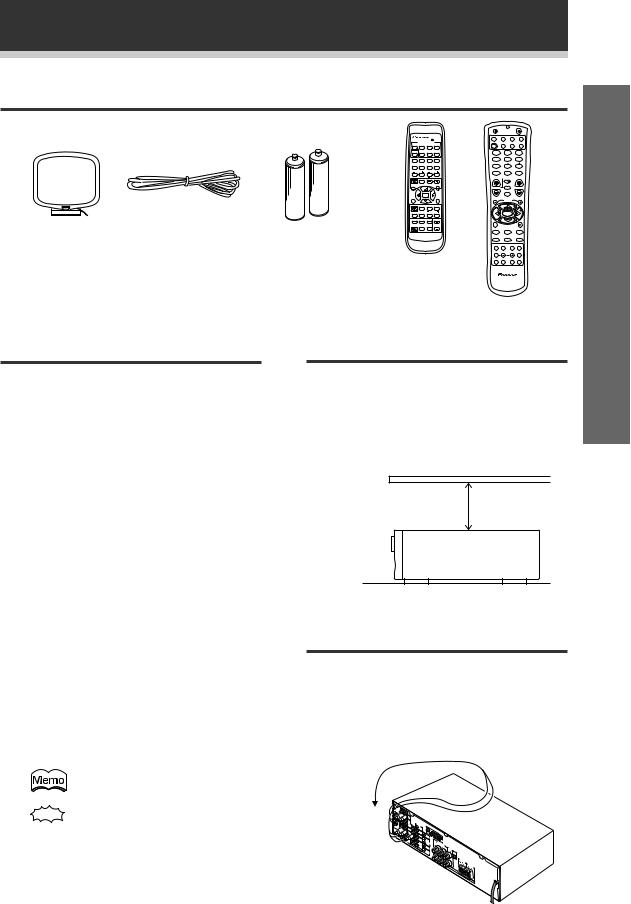
Checking the Supplied Accessories
Please check that you’ve received the following supplied accessories:
|
FM wire antenna |
AM loop antenna |
VSX-609RDS: |
|
AA size IEC R6P batteries (x2) |
|
VSX-709RDS: |
|
AA size IEC LR6 batteries (x2) |
Î
MULTI CONTROL
DVD/LD TV/SAT VCR/DVR CD
CD-R/
RECEIVER TUNER TAPE/MD TVCONT
2DSPMODE MIDNIGHT 5.1CH
1 |
2 |
3 |
4 |
|
CHANNEL |
TEST |
ATT |
SIGNAL |
|
SELECT |
TONE |
SELECT |
|
|
5 |
6 |
7 |
8 |
|
CHANNEL |
EFFECT |
|
||
LEVEL |
|
|||
9 |
0 |
‡ |
ENTER |
|
|
|
10 |
DISC |
|
|
FUNC |
CH |
|
|
|
|
|
|
|
VOL |
TV CONTROL |
VOL |
|
|
|
FQ |
|
|
|
ST |
|
ST |
|
|
|
ENTER |
TOP |
|
|
MENU |
|
|
MENU |
|
|
FQ |
|
|
|
SOUCE |
CLASS |
MPX |
BAND |
|
|
7 |
8 |
3 |
|
D.ACCESS |
|
CHANNEL |
|
|
|
DISPLAY |
RFATT |
|
|
1 ¡ 4 ¢
LOUDNESS FUNCTION MUTING
FL |
REMOTE MASTER |
RECEIVER DIMMER |
SETUP VOLUME |
AUDIO/VIDEOPRE-PROGRAMMED
REMOTECONTROLUNIT
VSX-609RDS
Remote control
SOURCE |
RECEIVER |
|
|
DVD |
TV |
VCR |
CD-R |
|
MULTI CONTROL |
|
|
RCV |
CD |
TUN |
TVC |
1 |
2 |
3 |
|
MIDNIGHT |
5.1CH |
ATT |
|
4 |
5 |
6 |
|
SIGNAL SELECT |
EFFECT |
||
7 |
8 |
9 |
|
+10 |
0 |
DISC |
|
TV CONTROL |
|
||
|
TV |
|
|
TV VOL |
TVFUNC MASTERVOLUME |
||
|
MENU |
|
|
|
CHANNEL |
|
|
|
|
FQ |
|
ST |
|
|
ST |
|
ENTER |
|
|
|
|
FQ |
|
8 |
|
|
|
D.ACCESS |
BAND |
CLASS |
|
3 |
1 |
¡ |
|
MPX |
DISPLAY |
RF ATT |
|
7 |
4 |
¢ |
|
2 |
DSP |
TEST TONE |
|
CH SELECT |
CH LEVEL |
FL DIMMER |
|
LOUDNESS FUNCTION |
MUTING |
SETUP |
|
|
|
|
Î |
AV PRE-PROGRAMMED AND LEARNING
REMOTE CONTROL UNIT
VSX-709RDS
Using this Manual
This manual is for the VSX-709RDS/ VSX-609RDS audio/video multi-channel receivers.
It is divided into two main sections:
Set up
This section covers installing your receiver and connecting up all the other components in your home theater system to it. It also describes how to set up a multi-channel speaker system to take full advantage of the great surround sound features of your receiver.
Installing the Receiver
Please note:
•Do not place objects directly on top of this unit.
This would prevent proper heat dispersal.
•When installing in a rack, shelf, etc., be sure to leave more than 20 cm of space above the receiver.
20 cm
Receiver
Operation
This section shows you how to use every feature of the receiver and its remote control. It also covers using the supplied remote control to operate your other home theater components. To find out more about a specific button, control or indicator, see Displays & Controls starting on page 28. This will point you to the relevant chapter in the manual.
In the Additional Information section (p.56 – 66) you’ll find a troubleshooting section and specifications.
The following symbols are used throughout this manual:
Provides detailed precautions and advice on operations, etc.
When Making Cable
Connections
Be careful not to arrange cables in a manner that bends the cables over the top of this unit as shown in the illustration. If the cables are brought over this unit, the magnetic field produced by the transformers in this unit may cause a humming noise to come from the speakers.
Indicates that display is blinking.
up Set
5
En
Introductory Information
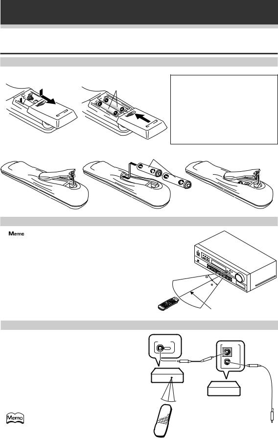
Preparing the Remote Control
Loading the batteries
VSX-609RDS
Dry cell batteries (AA size IEC R6P × 2)
VSX-709RDS |
Dry cell batteries |
|
(AA size IEC LR6 × 2) |
CAUTION!
Incorrect use of batteries may result in such hazards as leakage and bursting. Observe the following precautions:
¶Never use new and old batteries together.
¶Insert the plus and minus sides of the batteries properly according to the marks in the battery case.
¶Batteries with the same shape may have different voltages. Do not use different batteries together.
Operating range of remote control
 The remote control may not work properly if:
¶There are obstacles between the remote control and the receiver’s remote sensor.
¶Direct sunlight or fluorescent light is shining onto the remote sensor.
¶The receiver is located near a device that is emitting infrared rays.
¶The receiver is operated simultaneously with another infrared remote control.
30
30
7m
Operating other Pioneer components
By connecting a control cord (optional), you can control other Pioneer equipment using this remote control. Point the remote control towards the remote sensor of this unit, even when operating other equipment.
The remote control signals are received by the remote sensor of this unit, and sent to the other devices via the CONTROL OUT terminal.
CONTROL
OUT
VSX-709RDS/ VSX-609RDS
You can also control Pioneer components by pointing the receiver’s remote control directly at the component. This type of
operation does not require control cords.
Remote control
6
CONTROL
IN
OUT
Other Pioneer products with Î mark
Connect to CONTROL IN terminal of other Pioneer products with Î mark.
En
Connecting Your Equipment
Before making or changing the connections, switch off the power and disconnect the power cord from the AC outlet.
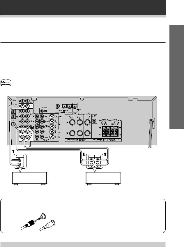
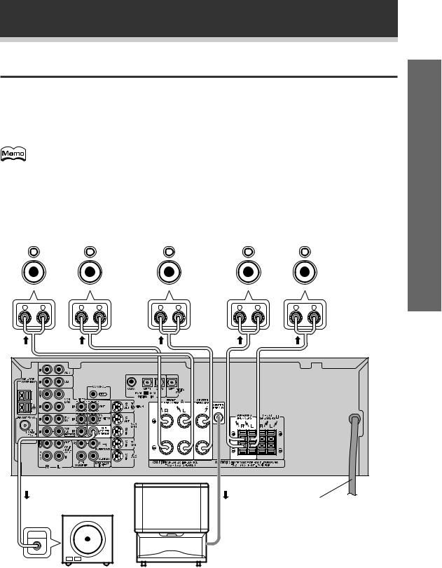
Audio Components
To begin set up connect your audio components to the jacks as shown below. These are all analog connections and your analog audio components (cassette deck etc.) use these jacks. Remember that for components you want to record with you need to hook up four plugs (a set of stereo ins and a set of stereo outs), but for components that only play you only need to hook up one set of stereo plugs (two plugs). To use Digital sources features you must hook up your digital components to the digital inputs, but it is also a good idea to hook up your digital components to analog audio jacks. If you want to record to/from digital components (like an MD) to/ from analog components you must hook up your digital equipment with these analog connections. See p.9, 10 for more on digital connections.
• Only the VSX-709RDS has S-video jacks and optical digital out jack. |
|
• The arrows indicate the direction of the audio signal. |
VSX-709RDS |
|
OUTPUT |
REC |
PLAY |
L |
|
L |
R |
|
R |
CD-R
CD player or Cassette deck or MD recorder
up Set
7 Audio cords
Use audio cords (not supplied) to connect the audio components.
R
L
Connect red plugs to R (right) and white plugs to L (left). Be sure to insert completely.
Cassette deck placement
Depending on where the cassette deck is placed, noise may occur during playback of your cassette deck which is caused by leakage flux from the transformer in the receiver. If you experience noise, move the cassette deck farther away from the receiver.
7
En

Connecting Your Equipment
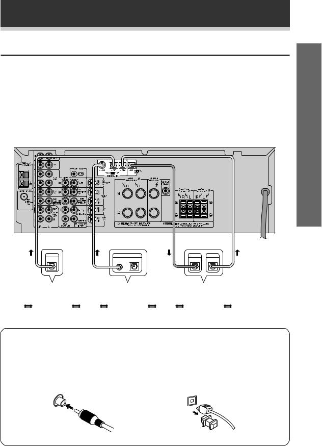
Video Components
Connect your video components to the jacks as shown below. Regarding digital video components (like a DVD player), you must use the analog connections pictured on this page for the video signal but in order to use a digital source you should hook up their audio to a digital input (see the next page). It is also a good idea to hook up your digital components with analog audio connections as well (see the previous page). To cover all possible laser discs a DVD/LD player or LD player requires an analog connection (as shown here) and two digital connections (see the next page).
TV tuner |
Video deck |
|
(or Satellite tuner) |
or DVR |
|
OUTPUT |
INPUT |
OUTPUT |
VIDEO |
VIDEO |
VIDEO |
L |
L |
L |
R |
R |
R |
|
|
VSX-709RDS |
VSX-709RDS only
7 Front
OUTPUT |
INPUT |
 VIDEO
VIDEO
VIDEO
L
Video R camera
(etc.)
DVD player |
TV |
|
|
(monitor) |
|
|
|
(or LD player) |
|
|
|
V |
L |
R |
|
|
VIDEO OUTPUT |
|
|
7 Audio/Video cords
Use audio/video cords (not supplied) to connect the video components and a video cord to connect the monitor TV.
R |
|
|
Connect red |
L |
|
plugs to R (right), |
|
|
VIDEO |
white plugs to L |
|
|
|
||
|
|
(left), and the |
|
|
|
|
|
|
|
|
yellow plugs to |
|
|
|
VIDEO. |
|
|
|
Be sure to insert |
|
|
|
completely. |
Front video connection are accessed via the front panel input selector as “VIDEO.”
VSX-709RDS only
If your video components have S-video jacks, you could use S-video cords (not supplied) to the S-video connector on the front and rear of the receiver.
However, if you use S-video cords for your video hookups you must also hook up your TV with S-video connections. Conversely, if you use regular composite video cords for video hookups, you should use them for your TV as well.
8
En
Connecting Your Equipment
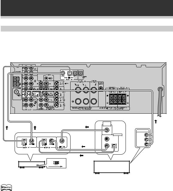
Digital Components
In order to hear PCM/Dolby Digital/DTS soundtracks you need to make digital audio connections. You can do this by either coaxial or optical connections (you do not need to do both). The quality of these two types of connections is the same, but since some digital components only have one type of digital terminal, it is a matter of matching like with like. The receiver has one coaxial and two optical inputs for a total of three digital inputs. You must assign the jacks to the proper component(s) (refer to pages 19 – 20).
Connect your digital components as shown below. There is one digital out jack (VSX-709RDS only). If you connect this to the optical input on a digital recorder (currently these include MD, DAT and CD-R), you can make direct digital recordings with this receiver.
|
Set |
VSX-709RDS |
up |
|
|
VSX-709RDS |
|
only |
|
DIGITAL |
DIGITAL OUT |
DIGITAL |
DIGITAL |
|
OUT |
COAX. |
OPT. |
IN |
OUT |
CD player |
|
DVD player |
|
CD-R |
|
|
or MD recorder |
||
|
|
|
|
or DAT |
7 Digital audio cords/Optical cables
Commercially available digital audio coaxial cords (standard video cords can also be used) or optical cables (not supplied) are used to connect digital components to this receiver.
When you use optical digital input or output terminals, pull off the caps and insert the plugs. Be sure to insert completely.
Digital audio cord |
Optical cable |
||
|
|||
(or standard video cord) |
|
||
|
|
|
|
9
En
Connecting Your Equipment
Example of connection using a DVD/LD or LD player
When playing an LD recorded in Dolby Digital
To connect a DVD/LD or LD player with its 2RF output, a commercially available RF demodulator (RFD-1) is required. The RF demodulator changes the digital signal to a form which can be processed by the VSX-709RDS/ VSX-609RDS models through their digital input jacks. For more details, refer to the instruction manual supplied with the RFD-1.
VSX-709RDS |
 RF OUT (AC-3)(LD)
OUTPUT
DIGITAL OUT |
VIDEO |
|
|
PCM (OPT.) |
|
1
L
R
2 3
DIGITAL IN |
|
OPTICAL COAXIAL |
DVD/LD player |
|
or LD player |
RF demodulator RFD-1
Make sure the RF demodulator digital in switch is set correctly (optical or coaxial depending on the connection).
10
En
Connecting Your Equipment
DVD 5.1 Channel Components
In some cases, you may need an external decoder to play special DVD discs and the like. If you find you need an external decoder, hook one up as shown below. For most people this component is unnecessary. (See p.40)
VSX-709RDS |
up Set |
Components equipped with 5.1 channel analog output jacks
The 5.1 channel input can only be used when DVD 5.1 CH is selected.
11
En
Connecting Your Equipment
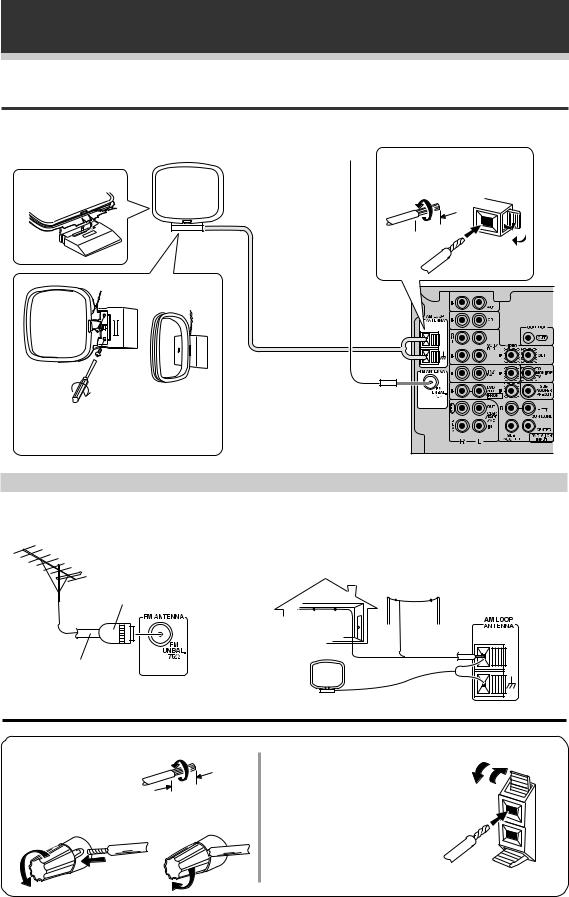
Antennas
Hook up the supplied radio antennas as shown below.
AM loop antenna |
FM wire antenna |
Assemble the antenna.
Twist exposed wire strands together and insert into the hole, then snap the connector shut. 
 10mm
10mm
Attach to a wall, etc. (if desired) and face toward the direction providing the best reception.
Connect the FM wire antenna and fully extend vertically along a window frame, etc.
Using external antennas
7 To improve FM reception |
7 To improve AM reception |
Connect an external FM antenna.
Connect a 5 – 6 meter length of vinyl-coated wire to the AM antenna terminal without disconnecting the supplied AM loop antenna.
For the best possible reception, suspend horizontally outdoors.
Outdoor antenna
PAL connector
Indoor antenna  (Vinyl-coated
wire)
5 – 6 m
75 Ω coaxial cable
7 Speaker terminals
1 Twist exposed wire |
|
strands together. |
|
2 Loosen speaker |
10 mm |
|
|
terminal and insert |
3 Tighten terminal. |
exposed wire. |
VSX-709RDS only
Use good quality speaker wire to connect the speakers to the receiver.
1Twist around 10 mm of bare wire strands together.
2Unclip the speaker terminal and insert the wire.
3Snap shut the speaker terminal to secure.
ª ·
12
En
Connecting Your Equipment
Speakers
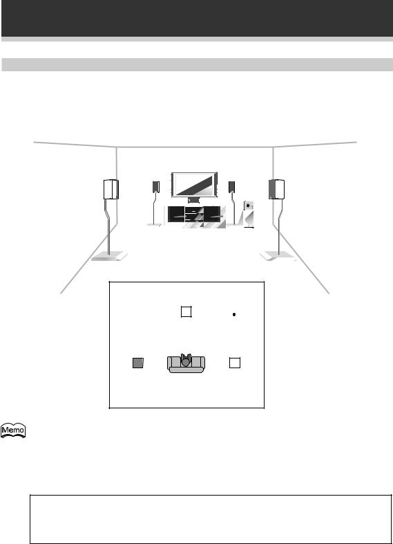
A full complement of six speakers is shown here but, naturally, everyone’s home setup will vary. Simply connect the speakers you have in the manner described below. The receiver will work with just two stereo speakers (called “front” speakers in the diagram) but it is recommended to be used with at least three speakers.
Make sure you connect the speaker on the right to the R (right) terminal and the speaker on the left to the L (left) terminal. Also make sure the positive and negative (+/–) terminals on the receiver match those on the speakers.
The receiver has two speaker systems, A & B. A is the main system supporting the full complement of surround sound speakers. If you switch on both A & B speaker systems, only the front speakers and the sub woofer will be audible. No sound will come from the center or surround speakers but multi channel sources will be down-mixed to the active speakers so no sound will be lost. Similarly, if you choose just the B system you‘ll only hear the speakers connected to the B system, and multi channel sources will be down-mixed to these two speakers. Please use speakers rated between 8 Ω – 16 Ω.
|
|
Front Speakers (A) |
Center Speaker |
|
Surround Speakers |
|||||||||||||||||||||||||||||||||
|
|
L |
|
|
|
R |
|
|
|
C |
|
|
SR |
|
|
|
SL |
|||||||||||||||||||||
|
|
|
|
|
|
|
|
|
|
|
|
|
|
|
|
|
|
|
|
|
|
|
|
|
|
|
|
|
|
|
|
|
|
|
|
|
|
|
|
|
|
|
|
|
|
|
|
|
|
|
|
|
|
|
|
|
|
|
|
|
|
|
|
|
|
|
|
|
|
|
|
|
|
|
|
|
|
up Set
VSX-709RDS |
TV
(To be used Powered sub woofer as the center
speaker)
INPUT
Be sure to complete all other connections before connecting this unit to the AC power source.
When using the speaker on your TV as the center speaker, connect the CENTER PREOUT jack on this unit to the audio input jack on your TV. In this case, the center speaker shown is unnecessary.
13
En
Connecting Your Equipment
Speaker placement
If you have a multiple speaker arrangement, the placement of the speakers is extremely important. To achieve the best possible surround sound, install your speakers as shown below. Make sure all speakers are installed securely to prevent accidents and improve sound quality. Be sure to consult your speaker manuals for the best placement of the speakers. Some speakers are designed to be floor-standing but others benefit greatly from speaker stands which raise them off the floor.
|
|
|
|
|
|
|
|
|
|
|
|
|
|
|
|
|
|
|
|
|
|
|
|
|
|
|
|
|
|
|
|
|
|
|
|
|
|
|
|
|
|
|
|
|
|
|
|
|
|
|
|
|
|
|
|
|
|
|
|
|
|
|
|
|
|
|
|
|
|
|
|
|
|
|
|
|
|
|
|
|
|
|
|
|
|
|
|
|
|
|
|
|
|
|
|
|
|
|
|
|
|
|
|
|
|
|
|
|
|
|
|
|
|
|
|
|
|
|
|
|
|
|
|
|
|
|
|
|
|
|
|
|
|
|
|
|
|
|
|
|
|
|
|
|
|
|
|
|
|
|
|
|
|
|
|
|
|
|
|
|
|
|
|
|
|
|
|
|
|
|
|
|
|
|
|
|
|
|
|
|
|
|
|
|
|
|
|
|
|
|
|
|
|
|
|
|
|
|
|
|
|
|
|
|
|
|
|
|
|
|
|
|
|
|
|
|
|
|
|
|
|
|
|
|
|
|
|
|
|
|
|
|
|
|
|
|
|
|
|
|
|
|
|
|
|
|
|
|
|
|
|
|
|
|
|
|
|
|
|
|
|
|
|
|
|
|
|
|
|
|
|
|
|
|
|
|
|
|
|
|
|
|
|
|
|
|
|
|
Front |
|
|
|
|
|
|
|
Front |
|
|
|
|
|
|
|
|||||||
|
|
|
|
|
|
|
|
|
|
|
|
|
|
|
|
|
|||||||||
|
|
|
|
|
|
|
|
|
|
|
|
|
|
|
|
|
|||||||||
|
|
|
Left |
Center |
Right |
|
|
|
|
|
|
|
|||||||||||||
|
|
|
|
|
|
|
|
|
|
|
|
|
|
|
|
|
|
|
|
|
|
|
|
|
|
|
|
|
|
|
|
|
|
|
|
|
|
|
|
|
|
|
|
|
|
|
|
|
|
|
|
|
|
|
|
|
|
|
|
|
|
|
|
|
|
|
|
|
|
|
|
|
|
|
|
|
|
Sub
Woofer
|
|
|
|
|
|
Surround |
Listening |
Surround |
|||
Left |
Right |
||||
Position |
|||||
|
|
|
|
||
• Install the left and right front speakers at equal distances from the TV.
•When installing speakers near the TV, we recommend using magnetically shielded speakers to prevent possible interference such as distortion in the color of the TV screen. If you do not have magnetically shielded speakers, and notice discoloration of the TV screen, place the speakers farther away from the TV.
•Install the center speaker above or below the TV so that the sound of the center channel is localized at the TV screen.
CAUTION:
When installing the center speaker on top of the TV, be sure to secure it with tape or some other suitable means. Otherwise, the speaker may fall from the TV due to external shocks such as earthquakes, and it may endanger those nearby or damage the speaker.
•If possible, install the surround speakers slightly above ear level.
•It may be difficult to obtain a cohesive surround effect if the surround speakers are installed farther away from the listening position than the front and center speakers.
14
En
Preparations
Before operating the receiver, be sure to press the main power button on the front panel to turn the power ON (_).
Setting Up for Surround Sound
To ensure the best possible surround sound, be sure to complete the following setup operations. This is particularly important when using the 2(Dolby)/DTS mode. You only need to make these settings once (unless you change the placement of your current speaker system or add new speakers, etc.). Refer to the following pages for detailed descriptions of the settings available for each mode.
VSX-709RDS |
|
|
|
|
|
SOURCE |
RECEIVER |
|
|
2 |
DVD |
TV |
VCR |
CD-R |
|
MULTI CONTROL |
|
||
RCV |
CD |
TUN |
TVC |
|
|
1 |
|
2 |
3 |
|
MIDNIGHT |
|
5.1CH |
ATT |
|
4 |
|
5 |
6 |
|
SIGNAL SELECT |
EFFECT |
|
|
|
7 |
|
8 |
9 |
|
+10 |
|
0 |
DISC |
|
TV CONTROL |
|
||
|
|
|
TV |
|
|
TV VOL |
|
TVFUNC MASTERVOLUME |
|
|
|
|
MENU |
|
|
|
CHANNEL |
|
|
|
|
|
FQ |
|
ENTER |
ST |
|
|
ST |
|
|
ENTER |
|
|
|
|
|
FQ |
|
|
8 |
|
|
|
|
D.ACCESS |
|
BAND |
CLASS |
|
3 1 ¡ |
|||
|
MPX |
DISPLAY |
RF ATT |
|
|
7 4 ¢ |
|||
VSX-609RDS |
|
|
|
|
|
|
|
|
Î |
|
MULTI CONTROL |
|
||
|
DVD/LD TV/SAT VCR/DVR |
CD |
||
2 |
|
|
CD-R/ |
|
RECEIVER TUNER TAPE/MD TVCONT |
||||
2 DSPMODE MIDNIGHT 5.1CH |
||||
|
1 |
2 |
3 |
4 |
CHANNEL |
TEST |
ATT |
SIGNAL |
SELECT |
TONE |
SELECT |
|
5 |
6 |
7 |
8 |
CHANNEL |
EFFECT |
||
LEVEL |
|||
9 |
0 |
10 |
DISC |
1
4
3
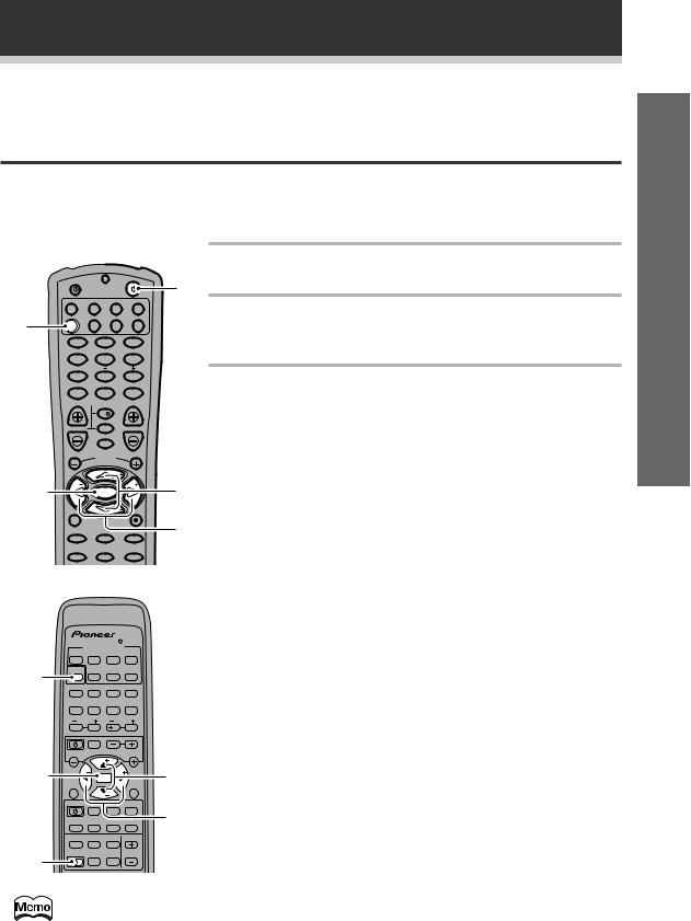
1 Press RECEIVER  to turn the power on.
The STANDBY indicator goes out.
2 Press RCV (VSX-709RDS) or RECEIVER (VSX609RDS).
This switches the remote control to the surround setup mode.
3 Press @ or #to select the mode you want to set.
For best results, start with “Speakers setting mode” and make your initial adjustments in the order described below.
The current settings are displayed automatically.
Speakers (Front, Center, Surround) setting mode (page 16)
Use to specify the type of speakers you have connected.
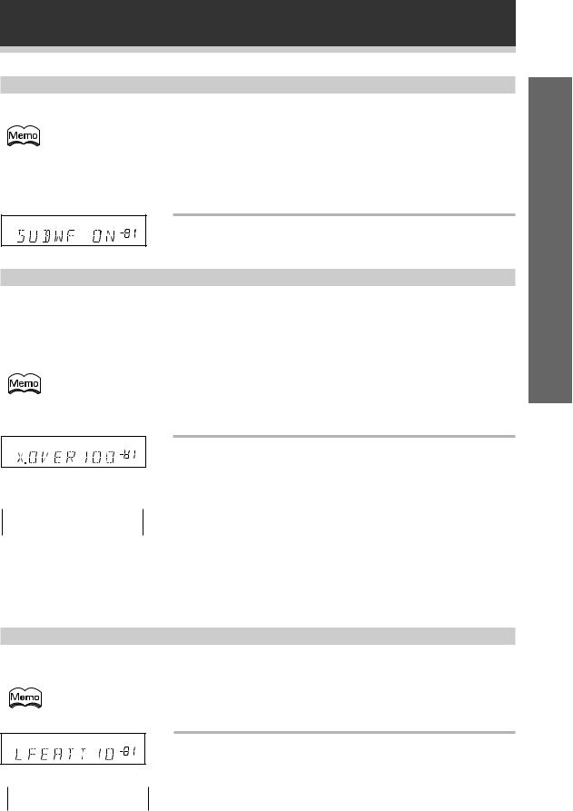
SUB WOOFER ON/PLUS/OFF setting mode (page 17)
Use to specify the sub woofer as on or off.
Crossover frequency setting mode (page 17)
Use to determine which frequencies will be sent to the sub woofer (or “Large” speakers if you don’t have a sub woofer).
LFE attenuator setting mode (page 17)
Use to specify the peak level for the LFE channel and the crossover network for rerouted bass frequencies.
Low cut filter ON/OFF setting mode (page 18)
Use to cut the distorted sound from the sub woofer.
FRONT speakers distance setting mode (page 18)
Use to specify the distance from your listening position to your front speaker.
CENTER speaker distance setting mode (page 18)
Use to specify the distance from your listening position to your center speaker.
SURROUND speakers distance setting mode (page 18)
ENTER
1
|
FUNC |
CH |
|
|
|
VOL |
TV CONTROL |
VOL |
|
||
|
FQ |
|
ST |
ST |
|
ENTER |
|
TOP |
MENU |
MENU |
FQ
SOURCE CLASS MPX BAND
|
7 |
8 |
3 |
D.ACCESS |
|
CHANNEL |
|
DISPLAY RFATT |
|
||
1 |
¡ |
4 |
¢ |
LOUDNESS FUNCTION MUTING
FL |
REMOTE MASTER |
RECEIVER DIMMER |
SETUP VOLUME |
4
3
Use to specify the distance from your listening position to your surround speakers.
Dynamic range control setting mode (page 19)
Use to compress the dynamic range of the soundtrack.
Dual mono setting mode (page 19)
Use with Dolby Digital software that has dual mono encoding if you want to isolate one channel or listen in this specialized mono mode.
Coaxial digital input setting (page 19)
Use to specify the input to be assigned to the coaxial digital input.
Optical digital input setting (page 20)
Use to specify the input to be assigned to the optical digital input.
Press ENTER to exit |
|
|
|
4 |
Press % or fi to select the setting you want. |
||
the setting mode. |
|||
The setting mode is |
|
The setting is entered automatically. |
|
automatically exited if |
|
||
|
|
||
no operation is per- |
|
|
|
5 |
Repeat steps 3 and 4 to set other surround |
||
formed within 20 sec- |
|||
onds. |
|
modes. |
up Set
15
En
Preparations
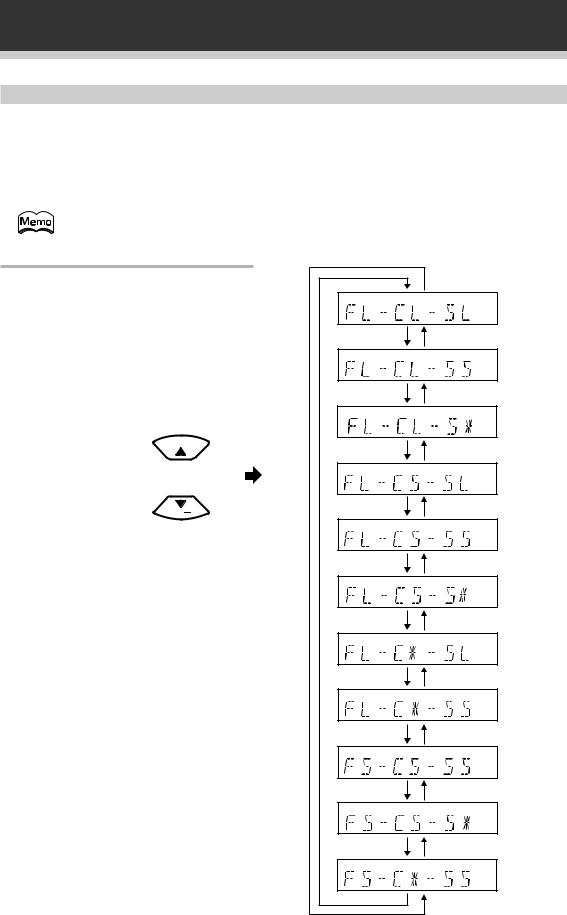
Speakers (Front, Center, Surround) setting mode
This setting establishes the size and configuration of the speaker system you have connected. So, for example, here you set whether you have connected surround speakers or not, and how big they are. Selecting “Large” or “Small” will determine how much bass is sent by the receiver to the speakers being set. This setup system has certain constraints. For example, all your speakers cannot be set to “Large.” You need to decide which speakers should receive the most bass and set them to “Large.”
In the display, “F”, “C”, and “S” refer to front, center, and surround speakers respectively. Speaker size is denoted as “L” for large speakers, “S” for small speakers, and “*” (asterisk) if no speaker is connected.
If the cone size (diameter) of the speaker is larger than 12 cm, please set to Large.
Switch the speakers setting mode according to the speakers you hooked up. Use the % or fi buttons.
The configurations shown on the right will appear in the display on the front of the receiver. One of them should match your speaker setup. Cycle through the different possibilities until you find the one that matches your setup.
FQ 
FQ
÷ Press #to advance to the next receiver setting, and press @ to return to a previous receiver setting.
16
En
Preparations
SUB WOOFER ON/PLUS/OFF setting mode
Sets whether the sub woofer is used or not. Also, when used you have the option to use the “PLUS” setting.
• Initial setting is “ON”.
• Setting the front speaker size to “Small” in the Speakers setting mode automatically locks the sub woofer in the “ON” position.
•Use the PLUS for extra bass. When you use PLUS, you will get the bass sounds from the sub woofer even if the front speakers are set to “Large”.
|
Press % or fi to select sub woofer ON, PLUS or |
dB |
OFF. |
Crossover frequency setting mode
Crossover frequency is the point where the receiver divides the high and low sounds (the frequencies) between the speakers. Since most smaller speakers can’t handle deep bass tones, this setting allows you to send those sounds to the sub woofer (or speakers set to “Large” if you don’t have a sub woofer) instead of the speakers set to “Small” in your system. Choose the point at which you want the frequency routed to the sub woofer (or “Large” speakers).
We recommend setting this to 200 Hz if smaller bookshelf-type speakers are used for your “Small” speakers.
•Initial setting is “100 Hz”.
•If all speakers (front, center, and surround) are set to “Large” in Speakers setting mode,
crossover frequency cannot be set because there are no “Small” speakers (*** appears in the display).
 Press % or fi to specify the crossover frequency dB for your small speakers (100 Hz, 150 Hz or 200
Hz).
 100Hz
100Hz
 150Hz
150Hz
 200Hz
200Hz
100 Hz
Sends bass frequencies below 100 Hz to the sub woofer (or “Large” speakers).
150 Hz
Sends bass frequencies below 150 Hz to the sub woofer (or “Large” speakers).
200 Hz
Sends bass frequencies below 200 Hz to the sub woofer (or “Large” speakers).
up Set
LFE attenuator setting mode
Dolby Digital and DTS audio sources include ultra-low bass tones. Set the LFE (Low Frequency Effect) attenuator as needed to prevent the ultra-low bass tones from distorting the sound from the speakers.
• Initial setting is “0 dB”.
• When ∞ is selected ( appears in the display), LFE is not available.
dB
Press % or fi to set the attenuation level (0 dB, 10 dB or dB(∞)).
 0 dB
0 dB 
 10 dB
10 dB
 ∞ (display "**")
17
En
Preparations
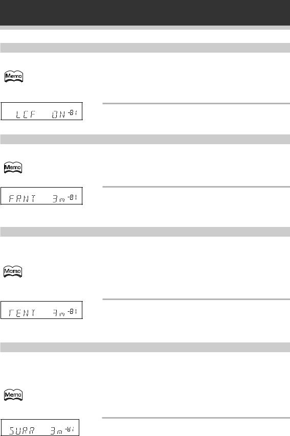
Low cut filter ON/OFF setting mode
Turn the low cut filter ON when distorted sound is output through the sub woofer.
• Initial setting is “OFF”.
• If the SUB WOOFER is set to “OFF” in the SUB WOOFER ON/OFF setting mode, the low cut filter cannot be set.
Press % or fi to select low cut filter ON or OFF.
dB
FRONT speakers distance setting mode
Sets the distance from the front speakers to the listening position.
• Adjust the speaker distance in 0.3 m increments from 0.3 m to 9.0 m.
• Initial setting is 3.0 m.
dB
Press % or fi to set the distance of the FRONT speakers from the main listening position (up to 30 steps).
CENTER speaker distance setting mode
Normally, the front and center speakers are placed at different distances from the listening position. This means that the sound from these speakers will not coincide. To compensate for this, set the center speaker distance setting.
• Adjust the speaker distance in 0.3 m increments from 0.3 m to 9.0 m.
•Initial setting is 3.0 m.
•When “C ” is selected in Speakers setting mode, the center distance cannot be set.
dB
Press % or fi to set the distance of the CENTER speaker from the main listening position (up to 30 steps).
SURROUND speakers distance setting mode
Adding the proper delay to the surround speakers is necessary to achieve a surround effect. The surround speakers are placed at various distances from the listening position. So to compensate for this, set the surround speakers distance setting.
• Adjust the speaker distance in 0.3 m increments from 0.3 m to 9.0 m.
• Initial setting is 3.0 m.
• When “S ” is selected in Speakers setting mode, the surround distance cannot be set.
dB
Press % or fi to set the distance of the
SURROUND speakers from the main listening position (up to 30 steps).
18
En
Preparations
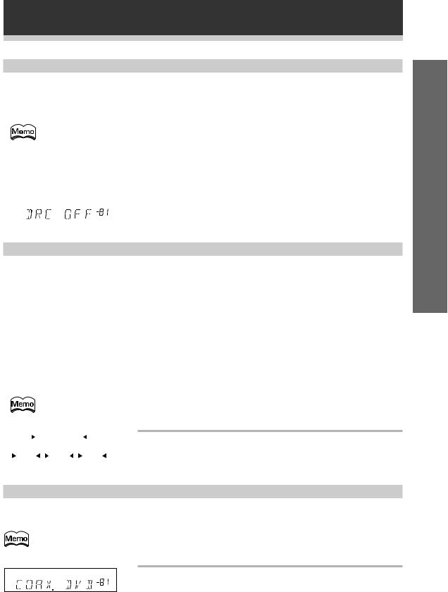
Dynamic range control setting mode
Dynamic range is the difference between the loudest and softest sounds in any given signal. The dynamic range control helps you play back sounds so the quieter sounds are audible yet the louder sounds don’t get distorted. It does this by compressing the dynamic range. When watching a movie at low volume, setting this function enables you to hear low level sounds to more easily but you won’t be jolted by lounder sounds.
• Initial setting is “OFF”.
•When the volume level is increased, set to “OFF”.
•For listening enjoyment at low volumes, set to “MAX” for maximum dynamic range compression.
•Dynamic range control is effective only when a Dolby Digital signal is being played back.
|
|
Press % or fi to set the dynamic range control |
dB |
|
(OFF, MAX, or MID). |
Dual mono setting mode
The dual mono setting can only be used when listening to Dolby Digital discs that contain a dual mono soundtrack. With this setting you can choose which channel is the dual mono setting you want to listen to. Thus, it is useful for soundtracks that have one language on one channel and a different language on the other. Remember you can only use this setting if you have Dolbly Digital software with this feature and want to isolate one of the channels therein.
There are two different ways to route the sound in the dual mono setting, one is with Dolby Digital mode on, the other with Dolby Digital mode off. If Dolby Digital mode is switched on, the ch1 setting will play channel 1 through your center speaker. The ch2 setting will play channel 2 though your center speaker and the MIX setting will play both channels through the center speaker. With Dolby Digital mode off, the dual mono sound routing is as follows: In the ch1 setting your will hear channel 1 out of both front speakers. In the ch2 setting you will hear channel 2 out of both speakers. In the L. c1 R. c2 setting the speakers will play the soundtrack independently of each other. The left front speaker will play channel 1 and the right front speaker will play channel 2. The last setting, MIX, mixes both channels and plays them out of both speakers .
• The default setting of this feature is L. c1 R. c2.
|
|
L. c 1 R. c 2 |
|
|
|
Press % or fi to cycle through the possible Dual |
||||
|
|
|
|
|
||||||
|
MIX |
|
ch2 |
|
|
ch1 |
|
mono settings. |
||
|
|
|
|
|
|
|||||
Coaxial digital input setting
Sets the input component to be assigned to the COAX (coaxial) digital input jack.
• Initial setting is “DVD”.
up Set
dB
Press % or fi to select the coaxial digital input
(DVD, TV, CD, CD-R, VCR, DVR or OFF).
After you assign the component to the COAX digital jack, when you select that component, for example DVD, the receiver will automatically change to the digital input setting. You can see this in the DIGITAL/ANALOG indicator on the front of the receiver.
19
En
Preparations
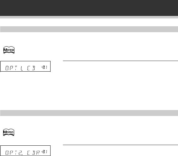
Optical digital input setting 1
Sets the input component to be assigned to the OPT 1 (optical) input jack.
• Initial setting is “CD”.
dB
Press % or fi to select the optical digital input 1
(DVD, TV, CD, CD-R, VCR, or OFF).
After you assign the component to the OPT 1 digital jack, when you select that component, for example CD, the receiver will automatically change to the digital input setting. You can see this in the DIGITAL/ ANALOG indicator on the front of the receiver.
Optical digital input setting 2
Sets the input component to be assigned to the OPT 2 (optical) input jack.
• Initial setting is “CD-R”.
dB
Press % or fi to select the optical digital input 2
(DVD, TV, CD, CD-R, VCR, or OFF).
After you assign the component to the OPT 2 digital jack, when you select that component, for example CD-R, the receiver will automatically change to the digital input setting. You can see this in the DIGITAL/ ANALOG indicator on the front of the receiver.
20
En
Preparations
Setting the Volume Level of Each Channel (Adjusting the Speaker Volume Balance)
• Test tone is only output in Dolby Digital/Dolby surround/DTS modes.
•Levels can be set for each surround mode.
•Initial setting is 0 dB.
•Since the SUB WOOFER transmits ultra-low frequencies, its sound may seem quieter than it actually is.
VSX-709RDS
1 Press RCV (VSX-709RDS) or RECEIVER (VSX-
SOURCE RECEIVER |
609RDS). |
1 |
DVD |
MULTI CONTROL |
CD-R |
|
|
This switches the remote control to the surround setup mode. |
|||
TV |
VCR |
|
|
|
|
|
|||
RCV |
CD |
TUN |
TVC |
|
|
|
|
|
|
|
1 |
2 |
3 |
|
2 |
Press 2. |
|
|
|
|
MIDNIGHT |
5.1CH |
ATT |
|
|
|
|||
|
4 |
5 |
6 |
|
|
|
|
|
|
|
SIGNAL SELECT |
EFFECT |
|
|
|
|
|
|
|
|
7 |
8 |
9 |
|
3 |
Press MASTER VOLUME + or – to adjust the |
|||
|
+10 |
0 |
DISC |
|
|||||
|
TV CONTROL |
|
|
|
|
volume to an appropriate level. |
|||
|
|
TV |
|
3 |
|
||||
|
TV VOL |
TVFUNC MASTERVOLUME |
|
|
|
|
|||
|
|
MENU |
|
4 |
Press TEST TONE to output the test tone. |
||||
|
|
CHANNEL |
|
|
|||||
|
|
|
FQ |
|
|
|
The test tone is output in the following order. |
||
|
ST |
|
|
ST |
|
|
|
|
|
|
|
ENTER |
|
|
|
|
CT |
FR |
|
|
|
|
FQ |
|
|
|
FL |
||
|
|
|
|
|
|
|
|
|
|
|
8 |
|
|
|
|
|
SW |
SL |
SR |
|
D.ACCESS |
BAND |
CLASS |
|
|
||||
|
3 1 ¡ |
|
|
|
|
|
|||
|
MPX |
DISPLAY |
RF ATT |
|
|
|
|
|
|
2 |
7 4 ¢ |
4,6 |
5 |
Adjust speaker levels so that you hear the test |
|||||
CH SELECT |
CH LEVEL FL DIMMER |
||||||||
|
2 |
DSP |
TEST TONE |
|
|
|
|
|
|
1 |
LOUDNESS FUNCTION |
MUTING |
SETUP |
|
tone at the same volume from each speaker |
||||
52 |
|
|
|
Î |
|
|
when seated in the main listening position. |
||
|
|
|
|
|
The channel level range is ± 10 dB. |
|
|||
|
|
|
|
|
|
|
|||
|
|
|
|
|
|
|
|
||
|
AV PRE-PROGRAMMED AND LEARNING |
|
|
|
|
|
|||
|
REMOTE CONTROL UNIT |
|
|
|
|
|
|||
|
|
|
|
|
|
6 |
Press TEST TONE to turn off the test tone. |
||
up Set
VSX-609RDS
1
2
1
5
2
|
|
|
Î |
|
|
MULTI CONTROL |
|
|
|
DVD/LD TV/SAT VCR/DVR |
CD |
|
||
|
|
CD-R/ |
|
|
RECEIVER TUNER TAPE/MD TVCONT |
|
|||
2 DSPMODE MIDNIGHT 5.1CH |
|
|||
1 |
2 |
3 |
4 |
4,6 |
CHANNEL |
TEST |
ATT |
SIGNAL |
|
SELECT |
TONE |
SELECT |
||
5 |
6 |
7 |
8 |
|
CHANNEL |
EFFECT |
|||
LEVEL |
||||
9 |
0 |
10 |
DISC |
|
|
FUNC |
|
CH |
|
|
|
|
|
|
VOL |
TV CONTROL |
VOL |
|
|
|
|
|
||
|
FQ |
|
|
|
ST |
ST |
|
||
|
ENTER |
TOP |
|
|
MENU |
|
|
|
|
|
|
MENU |
||
|
FQ |
|
|
|
SOURCE CLASS |
MPX |
BAND |
|
|
|
7 |
8 |
3 |
|
D.ACCESS |
|
CHANNEL |
|
|
|
DISPLAY RF ATT |
¢ |
||
1 |
¡ |
4 |
||
LOUDNESS FUNCTION |
MUTING |
3 |
||
RECEIVER |
FL |
REMOTE MASTER |
||
DIMMER |
SETUP |
VOLUME |
||
AUDIO/VIDEOPRE-PROGRAMMED
REMOTECONTROLUNIT
The speaker volume balance can be adjusted without outputting the test tone by pressing CH (CHANNEL) SELECT and CH (CHANNEL) LEVEL +/–.
1Press CH (CHANNEL) SELECT to select the channel you want to adjust.
2 Press CH (CHANNEL) LEVEL + or – to adjust the volume.
21
En
 Loading...