


VSX-52

VSX-53
VSX-52
IMPORTANT
CAUTION
RISK OF ELECTRIC SHOCK
The lightning flash with arrowhead symbol,
within an equilateral triangle, is intended to
alert the user to the presence of uninsulated
“dangerous voltage” within the product’s
enclosure that may be of sufficient
magnitude to constitute a risk of electric
shock to persons.
WARNING
This equipment is not waterproof. To prevent a fire or
shock hazard, do not place any container filled with
liquid near this equipment (such as a vase or flower
pot) or expose it to dripping, splashing, rain or
moisture.
WARNING
Before plugging in for the first time, read the following
section carefully.
The voltage of the available power supply differs
according to country or region. Be sure that the
power supply voltage of the area where this unit
will be used meets the required voltage (e.g., 230 V
or 120 V) written on the rear panel.
VENTILATION CAUTION
When installing this unit, make sure to leave space
around the unit for ventilation to improve heat radiation
(at least 40 cm at top, 10 cm at rear, and 20 cm at each
side).
WARNING
Slots and openings in the cabinet are provided for
ventilation to ensure reliable operation of the product,
and to protect it from overheating. To prevent fire
hazard, the openings should never be blocked or
covered with items (such as newspapers, table-cloths,
curtains) or by operating the equipment on thick carpet
or a bed.
CAUTION:
TO PREVENT THE RISK OF ELECTRIC
SHOCK, DO NOT REMOVE COVER (OR
BACK). NO USER-SERVICEABLE PARTS
INSIDE. REFER SERVICING TO QUALIFIED
SERVICE PERSONNEL.
D3-4-2-1-3_A1_En
D3-4-2-1-4*_A1_En
D3-4-2-1-7b*_A1_En
DO NOT OPEN
The exclamation point within an equilateral
triangle is intended to alert the user to the
presence of important operating and
maintenance (servicing) instructions in the
literature accompanying the appliance.
WARNING
To prevent a fire hazard, do not place any naked flame
sources (such as a lighted candle) on the equipment.
Operating Environment
Operating environment temperature and humidity:
+5 °C to +35 °C (+41 °F to +95 °F); less than 85 %RH
(cooling vents not blocked)
Do not install this unit in a poorly ventilated area, or in
locations exposed to high humidity or direct sunlight (or
strong artificial light)
If the AC plug of this unit does not match the AC
outlet you want to use, the plug must be removed
and appropriate one fitted. Replacement and
mounting of an AC plug on the power supply cord of
this unit should be performed only by qualified
service personnel. If connected to an AC outlet, the
cut-off plug can cause severe electrical shock. Make
sure it is properly disposed of after removal.
The equipment should be disconnected by removing
the mains plug from the wall socket when left unused
for a long period of time (for example, when on
vacation).
CAUTION
The STANDBY/ON switch on this unit will not
completely shut off all power from the AC outlet.
Since the power cord serves as the main disconnect
device for the unit, you will need to unplug it from the
AC outlet to shut down all power. Therefore, make
sure the unit has been installed so that the power
cord can be easily unplugged from the AC outlet in
case of an accident. To avoid fire hazard, the power
cord should also be unplugged from the AC outlet
when left unused for a long period of time (for
example, when on vacation).
D3-4-2-1-1_A1_En
D3-4-2-1-7a_A1_En
D3-4-2-1-7c*_A1_En
D3-4-2-2-1a_A1_En
D3-4-2-2-2a*_A1_En
Only use attachments/accessories specified by
Read these instructions.
1)
Keep these instructions.
2)
Heed all warnings.
3)
Follow all instructions.
4)
Do not use this apparatus near water.
5)
Clean only with dry cloth.
6)
Do not block any ventilation openings. Install in
7)
accordance with the manufacturer’s
instructions.
Do not install near any heat sources such as
8)
radiators, heat registers, stoves, or other
apparatus (including amplifiers) that produce
heat.
Do not defeat the safety purpose of the polarized
9)
or grounding-type plug. A polarized plug has two
blades with one wider than the other. A
grounding type plug has two blades and a third
grounding prong. The wide blade or the third
prong are provided for your safety. If the provided
plug does not fit into your outlet, consult an
electrician for replacement of the obsolete outlet.
Protect the power cord from being walked on or
10)
pinched particularly at plugs, convenience
receptacles, and the point where they exit from
the apparatus.
NOTE:
This equipment has been tested and found to comply with the limits for a Class B digital device, pursuant to Part 15
of the FCC Rules. These limits are designed to provide reasonable protection against harmful interference in a
residential installation. This equipment generates, uses, and can radiate radio frequency energy and, if not installed
and used in accordance with the instructions, may cause harmful interference to radio communications. However,
there is no guarantee that interference will not occur in a particular installation. If this equipment does cause
harmful interference to radio or television reception, which can be determined by turning the equipment off and on,
the user is encouraged to try to correct the interference by one or more of the following measures:
— Reorient or relocate the receiving antenna.
— Increase the separation between the equipment and receiver.
— Connect the equipment into an outlet on a circuit different from that to which the receiver is connected.
— Consult the dealer or an experienced radio/TV technician for help.
Caution
To prevent fire hazard, the Class 2 Wiring Cable
should be used for connection with speaker, and
should be routed away from hazards to avoid damage
to the insulation of the cable.
Information to User
Alterations or modifications carried out without
appropriate authorization may invalidate the user’s
right to operate the equipment.
D3-7-13-67*_A1_En
D8-10-2_A1_En
11)
the manufacturer.
Use only with the cart, stand, tripod, bracket, or
12)
table specified by the manufacturer, or sold with
the apparatus. When a cart is used, use caution
when moving the cart/apparatus combination to
avoid injury from tip-over.
Unplug this apparatus during lightning storms
13)
or when unused for long periods of time.
Refer all servicing to qualified service personnel.
14)
Servicing is required when the apparatus has
been damaged in any way, such as power-supply
cord or plug is damaged, liquid has been spilled
or objects have fallen into the apparatus, the
apparatus has been exposed to rain or moisture,
does not operate normally, or has been dropped.
D3-7-13-69_En
D8-10-1-2_A1_En
WARNING: Handling the cord on this product or
cords associated with accessories sold with the
product may expose you to chemicals listed on
proposition 65 known to the State of California and
other governmental entities to cause cancer and
birth defect or other reproductive harm.
D36-P5_B1_En
En
2

IMPORTANT NOTICE
THE MODEL NUMBER AND SERIAL NUMBER OF
THIS EQUIPMENT ARE ON THE REAR OR BOTTOM.
RECORD THESE NUMBERS ON YOUR ENCLOSED
WARRANTY CARD AND KEEP IN A SAFE PLACE
FOR FUTURE REFERENCE.
CAUTION
This product satisfies FCC regulations when shielded
cables and connectors are used to connect the unit
to other equipment. To prevent electromagnetic
interference with electric appliances such as radios
and televisions, use shielded cables and connectors
for connections.
This product is for general household purposes. Any
failure due to use for other than household purposes
(such as long-term use for business purposes in a
restaurant or use in a car or ship) and which requires
repair will be charged for even during the warranty
period.
This Class B digital apparatus complies with
Canadian ICES-003.
CAUTION:
HOT SURFACE. DO NOT TOUCH.
The top surface over the internal
heatsink may become hot when
operating this product continuously.
D36-AP9-1_A1_En
D8-10-3a_A1_En
K041_A1_En
D8-10-1-3_A1_En
The Safety of Your Ears is in Your Hands
Get the most out of your equipment by playing it at a
safe level – a level that lets the sound come through
clearly without annoying blaring or distortion and, most
importantly, without affecting your sensitive hearing.
Sound can be deceiving. Over time, your hearing
“comfort level” adapts to higher volumes of sound, so
what sounds “normal” can actually be loud and
harmful to your hearing. Guard against this by setting
your equipment at a safe level BEFORE your hearing
adapts.
ESTABLISH A SAFE LEVEL:
• Set your volume control at a low setting.
• Slowly increase the sound until you can hear it
comfortably and clearly, without distortion.
• Once you have established a comfortable sound
level, set the dial and leave it there.
BE SURE TO OBSERVE THE FOLLOWING
GUIDELINES:
• Do not turn up the volume so high that you can’t
hear what’s around you.
• Use caution or temporarily discontinue use in
potentially hazardous situations.
• Do not use headphones while operating a motorized
vehicle; the use of headphones may create a traffic
hazard and is illegal in many areas.
S001a_A1_En
En
3

Thank you for buying this Pioneer
product. Please read through these
operating instructions so you will
know how to operate your model
properly. After you have finished reading the instructions, put them away
in a safe place for future reference.
Contents
01 Before you start
Our philosophy ................................................ 6
Features ...........................................................6
Checking what’s in the box ............................ 6
Installing the receiver ..................................... 6
Loading the batteries ...................................... 6
Operating range of remote control unit........ 7
About using AVNavigator (included
CD-ROM) .........................................................7
02 Controls and displays
Remote control ............................................... 8
Display ............................................................. 9
Front panel .................................................... 10
03 Connecting your equipment
Connecting your equipment ........................ 11
Rear panel ..................................................... 11
Determining the speakers’ application ...... 12
Placing the speakers .................................... 13
Connecting the speakers ............................. 13
Installing your speaker system .................... 14
Selecting the Speaker system ..................... 15
About the audio connection ........................16
About the video converter ............................ 16
About HDMI ..................................................16
Connecting your TV and playback
components .................................................. 17
Connecting an HDD/DVD recorder, BD
recorder and other video sources ............... 19
Connecting a satellite/cable receiver or
other set-top box ........................................... 19
Connecting other audio components ......... 20
En
4
Connecting additional amplifiers ................ 20
Connecting AM/FM antennas ..................... 21
MULTI-ZONE setup ....................................... 21
Connecting a SiriusConnect Tuner ............. 22
Connecting to the network through
LAN interface ................................................22
Connecting optional Bluetooth
ADAPTER ...................................................... 22
Connecting an iPod ...................................... 23
Connecting a USB device ............................ 23
Connecting an HDMI-equipped
component to the front panel input ............ 23
Connecting to a wireless LAN ..................... 23
Connecting an IR receiver ........................... 23
Operating other Pioneer components
with this unit’s sensor .................................. 24
Switching components on and off
using the 12 volt trigger ................................ 24
Plugging in the receiver ............................... 25
04 Basic Setup
Switching the speaker impedance ............. 26
Changing the OSD display language
(OSD Language) ........................................... 26
Automatically conducting optimum
sound tuning (Full Auto MCACC) ............... 26
The Input Setup menu .................................. 28
Operation Mode Setup ................................. 28
05 Basic playback
Playing a source ........................................... 30
Playing an iPod ............................................. 30
Playing a USB device ................................... 31
Listening to the radio .................................... 33
Listening to Satellite Radio .......................... 33
Bluetooth ADAPTER for Wireless
Enjoyment of Music ...................................... 35
06 Listening to your system
Enjoying various types of playback
using the listening modes ........................... 37
Selecting MCACC presets ........................... 39
Choosing the input signal ............................ 39
Better sound using Phase Control ..............39
Better sound using Phase Control and
Full Band Phase Control .............................. 39
07 Playback with HOME MEDIA
GALLERY inputs
Enjoying the Home Media Gallery ............... 41
Features of Home Media Gallery ................. 41
Introduction ................................................... 41
Playback with Home Media Gallery ............ 42
Advanced operations for Internet radio ...... 43
Checking about the Accounts ..................... 43
About network playback............................... 44
About playable file formats .......................... 45
08 Control with HDMI function
About the Control with HDMI function .......47
Making Control with HDMI connections .... 47
HDMI Setup................................................... 47
Before using synchronization ...................... 48
About synchronized operations .................. 48
Setting the PQLS function ...........................48
Cautions on the Control with HDMI
function ......................................................... 49
09 Using other functions
Setting the Audio options ............................ 50
Setting the Video options ............................. 52
Switching the speaker terminals ................ 53
Using the MULTI-ZONE controls ................. 53
Making an audio or a video recording ........ 54
Reducing the level of an analog signal ....... 54
Using the sleep timer ................................... 54
Dimming the display ....................................54
Switching the HDMI output ......................... 54
Checking your system settings ................... 55
Resetting the system ....................................55
10 Controlling the rest of your system
About the Remote Setup menu................... 56
Operating multiple receivers ....................... 56
Setting the remote to control other
components .................................................. 56
Selecting preset codes directly ................... 56
Programming signals from other
remote controls ............................................. 57
Erasing one of the remote control
button settings .............................................. 57
Erasing all learnt settings that are in
one input function ........................................57
Direct function .............................................. 57
Setting the backlight mode ......................... 58
Multi Operation and System Off .................. 58
Resetting the remote control settings ........59
Controlling components .............................. 59
11 The Advanced MCACC menu
Making receiver settings from the
Advanced MCACC menu ............................. 62
Automatic MCACC (Expert) ......................... 62
Manual MCACC setup ................................. 64
Checking MCACC Data ................................66
Data Management........................................ 67
12 The System Setup and Other
Setup menus
Making receiver settings from the
System Setup menu .....................................69
Manual speaker setup ..................................69
Network Setup menu ................................... 71
Checking the Network Information ............. 73
The Other Setup menu ................................. 73
13 Additional information
Troubleshooting 1 ......................................... 76
Troubleshooting 2 ......................................... 82
Troubleshooting of wireless LAN ................ 85
About status messages ............................... 86
Speaker Setting Guide.................................. 86
Important information regarding the
HDMI connection ......................................... 87
Cleaning the unit .......................................... 87
Surround sound formats ............................. 88
About THX ..................................................... 88
About iPod ..................................................... 89
About SIRIUS ................................................ 89
About FLAC ................................................... 89
Auto Surround, ALC and Stream Direct
with different input signal formats ..............90
Glossary ......................................................... 91
Features index ............................................... 94
Specifications ............................................... 95
Preset code list.............................................. 96

Flow of settings on the receiver
Flow for connecting and setting the receiver
The unit is a full-fledged AV receiver equipped with an abundance of functions and terminals. It can
be used easily after following the procedure below to make the connections and settings.
Required setting item: 1, 2, 3, 4, 6, 8, 10
Setting to be made as necessary: 5, 7, 9, 11, 12, 13, 14
Important
The receiver’s initial settings can be made on the computer using Wiring Navi on the AVNavigator
CD-ROM included with the receiver. In this case, virtually the same connections and settings as
in steps 2, 3, 4, 6, 7, 8 and 9 can be made interactively. For instructions on using AVNavigator, see
About using AVNavigator (included CD-ROM) on page 7 .
1 Before you start
! Checking what’s in the box on page 6
! Loading the batteries on page 6
j
2 Determining the speakers’ application (page 12)
! 7.2 channel surround system (Front height)
! 7.2 channel surround system (Front wide)
! 7.2 channel surround system & Speaker B connection
! 5.2 channel surround system & Front Bi-amping connection (High quality surround)
! 5.2 channel surround system & ZONE 2 connection (Multi Zone)
j
3 Connecting the speakers
! Placing the speakers on page 13
! Connecting the speakers on page 13
! Installing your speaker system on page 14
! Bi-amping your speakers on page 15
j
4 Connecting the components
! About the audio connection on page 16
! About the video converter on page 16
! Connecting your TV and playback components on page 17
! Connecting AM/FM antennas on page 21
! Plugging in the receiver on page 25
j
5 Switching the speaker impedance (page 26)
(Only if the impedance of the connected speakers is 6 W to 8 W)
j
6 Power On
j
7 Changing the OSD display language (OSD Language) (page 26)
j
8 MCACC speaker settings
! Automatically conducting optimum sound tuning (Full Auto MCACC) on page 26
j
9 The Input Setup menu (page 28)
(When using connections other than the recommended connections)
j
10 Basic playback (page 30)
j
11 Switching the HDMI output (page 54)
VSX-53 only
j
12 Adjusting the sound and picture quality as desired
! Using the various listening modes (page 37)
! Better sound using Phase Control (page 39)
! Better sound using Phase Control and Full Band Phase Control (VSX-53 only) (page 39)
! Measuring the all EQ type (SYMMETRY/ALL CH ADJ/FRONT ALIGN) (page 62)
! Changing the channel level while listening (page 70)
! Switching on/off the Acoustic Calibration EQ, Auto Sound Retriever or
Dialog Enhancement (page 50)
! Setting the PQLS function (page 48)
! Setting the Audio options (page 50)
! Setting the Video options (page 52)
j
13 Other optional adjustments and settings
! Control with HDMI function (page 47)
! The Advanced MCACC menu (page 62)
! The System Setup and Other Setup menus (page 69)
j
14 Making maximum use of the remote control
! Operating multiple receivers (page 56)
! Setting the remote to control other components (page 56)
En
5
01 Before you start
Before you start
Our philosophy
Pioneer is dedicated to making your home
theater listening experience as close as possible to the vision of the moviemakers and mastering engineer when they created the original
soundtrack. We do this by focusing on three
important steps:
1 Designing with carefully selected
components so as to transmit the original
soundtrack accurately
2 Allowing for customized acoustic
calibration according to any listening area
3 Tuning that transmits soul
Features
% HDMI (3D, Audio Return Channel)
A compatible component is required to use the
above function.
% HOME MEDIA GALLERY
This receiver can play back contents stored
on your computer when your computer is connected to the LAN terminal of this receiver.
% About operation of the receiver with a
mobile terminal (iPod, iPhone, etc.)
The receiver can be controlled from the mobile
terminal by installing a special application on
the mobile terminal. For details, see the product
information on the Pioneer website.
This special application may be changed or
discontinued without notice.
% Remote operation on an iPod touch/
iPhone/iPad
Operation via LAN is possible from an iPod
touch, iPhone or iPad by downloading a
Pioneer original application (iControlAV2) from
the iTunes Store.
En
6
% AVNavigator
The CD-ROM (AVNavigator) included with this
unit provides a variety of functions, such as
Wiring Navi with a guide for connecting the
unit and setting up from the computer and an
Interactive Manual for operating the unit while
reading the manual.
% PQLS
Jitterless high quality playback is possible by
connecting a PQLS-compatible player with
HDMI connections.
% iPod playback
Your iPod can be connected to the receiver’s
USB terminal to play the music/video files on
the iPod.
Also, the iPod is charged when it is connected
to the receiver.
% Advanced Direct Energy design
This receiver offers a new advancement in discrete design unique to Pioneer for high-power
drivability, low distortion and stable imaging.
% Dolby Pro Logic llz compatible
Adding a pair of speakers above the front left
and right speakers adds expressiveness in the
vertical direction to the previous horizontallyoriented sound field. The height channel
strengthens the sound field’s sense of threedimensionality and air, producing presence and
expansion.
% Internet Radio
By connecting this receiver to the network via
the LAN terminal, you can listen to Internet
radio stations.
% SIRIUS Ready
With the SIRIUS Radio terminal, you’ll be up
and running in no time.
% Bluetooth compatible
Using the Bluetooth ADAPTER (AS-BT100 or
AS-BT200) lets you enjoy music files on an
iPhone or other Bluetooth wireless technology
device wirelessly.
% Auto Sound Retriever
The Auto Sound Retriever feature employs
DSP technology to restore sound pressure
and smooth jagged artifacts left over after
compression.
% Easy setup using Advanced MCACC
The Auto MCACC Setup provides a quick but
accurate surround sound setup, which includes
the advanced features of Professional Acoustic
Calibration EQ.
Checking what’s in the box
Please check that you’ve received the following
supplied accessories:
! Setup microphone (cable: 5 m (16.4 ft.))
! Remote control unit
! AAA size IEC R03 dry cell batteries (to confirm
system operation) x2
! AM loop antenna
! FM wire antenna
! iPod cable
! Power cord
! CD-ROM (AVNavigator)
! Warranty card
! These operating instructions
Installing the receiver
! When installing this unit, make sure to put it
on a level and stable surface.
! Don’t install it on the following places:
— on a color TV (the screen may distort)
— near a cassette deck (or close to a device that
gives off a magnetic field). This may interfere
with the sound.
— in direct sunlight
— in damp or wet areas
— in extremely hot or cold areas
— in places where there is vibration or other
movement
— in places that are very dusty
— in places that have hot fumes or oils (such as
a kitchen)
! Do not touch this receiver’s bottom panel
while the power is on or just after it is turned
off. The bottom panel becomes hot when the
power is on (or right after it is turned off) and
could cause burns.
Loading the batteries
The batteries included with the unit are to check
initial operations; they may not last over a long
period. We recommend using alkaline batteries
that have a longer life.
WARNING
! Do not use or store batteries in direct sunlight
or other excessively hot place, such as inside a
car or near a heater. This can cause batteries
to leak, overheat, explode or catch fire. It
can also reduce the life or performance of
batteries.
CAUTION
Incorrect use of batteries may result in such
hazards as leakage and bursting. Observe the
following precautions:
! Never use new and old batteries together.
! Insert the plus and minus sides of the
batteries properly according to the marks in
the battery case.
Before you start
01
! Batteries with the same shape may have
different voltages. Do not use different
batteries together.
! When disposing of used batteries, please
comply with governmental regulations or
environmental public instruction’s rules that
apply in your country or area.
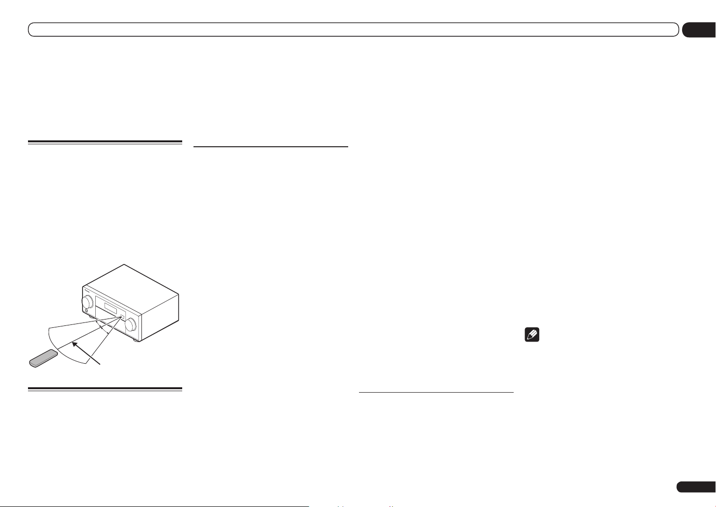
Operating range of remote
control unit
The remote control may not work properly if:
! There are obstacles between the remote
control and the receiver’s remote sensor.
! Direct sunlight or fluorescent light is shining
onto the remote sensor.
! The receiver is located near a device that is
emitting infrared rays.
! The receiver is operated simultaneously with
another infrared remote control unit.
30°
30°
7 m (23 ft.)
About using AVNavigator
(included CD-ROM)
The included AVNavigator CD-ROM contains
Wiring Navi allowing you to easily make the
receiver’s connections and initial settings in
dialog fashion. High precision initial settings
can be completed easily simply by following the
instructions on the screen to make the connections and settings.
There are also other features enabling easy use
of various functions, including an Interactive
Manual that operates in association with the
receiver, updating of various types of software,
and MCACC Application that lets you check the
MCACC measurement results on 3D graphs.
Installing AVNavigator
1 Load the included AVNavigator
CD-ROM into your computer’s CD drive.
! The installation screen is displayed. Proceed
to step 2.
! If the installation screen does not appear,
double-click on the CD-ROM icon then start
the installer (AVNV_XXX_xxx.exe).
2 Follow the instructions on the screen
to install.
When “Finish” is selected, installation is
completed.
3 Remove the included AVNavigator
CD-ROM from the computer’s CD drive.
Handling the CD-ROM
Operating Environment
! This CD-ROM can be used with Microsoft®
Windows® XP/Vista/7.
! A browser is at times used for AVNavigator
functions. The supported browser is Microsoft
Internet Explorer 6, 7 and 8. With other
browsers, some functions may be limited or
the display may not appear properly.
Also, even with a supported browser,
depending on the browser’s settings, some
functions may be limited and the display may
not appear properly.
Precautions For Use
! This CD-ROM is for use with a personal
computer. It cannot be used with a DVD
player or music CD player. Attempting to play
this CD-ROM with a DVD player or music
CD player can damage speakers or cause
impaired hearing due to the large volume.
License
! Please agree to the “Terms of Use” indicated
below before using this CD-ROM. Do not use if
you are unwilling to consent to the terms of its
use.
Also agree to the “License Agreement”
displayed when installing AVNavigator.
Terms of Use
! Copyright to data provided on this CD-ROM
belongs to PIONEER CORPORATION.
Unauthorized transfer, duplication, broadcast,
public transmission, translation, sales,
lending or other such matters that go beyond
the scope of “personal use” or “citation” as
defined by Copyright Law may be subject
to punitive actions. Permission to use this
CD-ROM is granted under license by PIONEER
CORPORATION.
General Disclaimer
! PIONEER CORPORATION does not
guarantee the operation of this CD-ROM with
respect to personal computers using any
of the applicable OS. In addition, PIONEER
CORPORATION is not liable for any damages
incurred as a result of use of this CD-ROM
and is not responsible for any compensation.
The names of private corporations, products
and other entities described herein are the
registered trademarks or trademarks of their
respective firms.
Using AVNavigator
1 Click [AVNavigator] on the desktop to
launch AVNavigator.
AVNavigator is launched and Wiring Navi
starts up. The language selection screen
appears. Follow the instructions on the screen
to make the connections and automatic
settings.
Wiring Navi only starts up automatically the
first time AVNavigator is launched.
2 Select and use the desired function.
AVNavigator includes the following functions:
! Wiring Navi – Guides you through
connections and initial settings in dialog
fashion. High precision initial settings can be
made easily.
! Interactive Manual – Automatically displays
the pages explaining the functions that have
been operated on the receiver. It is also
possible to operate the receiver from the
Interactive Manual.
! Glossary – Displays glossary pages.
! MCACC Appli – Displays Advanced
MCACC measurement results vividly on the
computer.
There are special operating instructions
for MCACC Application. These instructions
are included in the AVNavigator
Interactive Manual’s menus. Refer to them
when using MCACC Application.
! Software Update – Allows various types of
software to be updated.
! Settings – Used to make various
AVNavigator settings.
! Detection – Used to detect the receiver.
Note
To use the AVNavigator of another model, first
uninstall (delete) this receiver’s AVNavigator,
then install the AVNavigator of the other model.
Deleting the AVNavigator
You can use the following method to uninstall
(delete) the AVNavigator from your PC.
% Delete from the Control Panel of the
PC.
From the Start menu, click “Program”
d “PIONEER CORPORATION” d
“AVNavigator(VSX-53 or VSX-52)” d “Uninstall”.
En
7
02 Controls and displays
Controls and displays
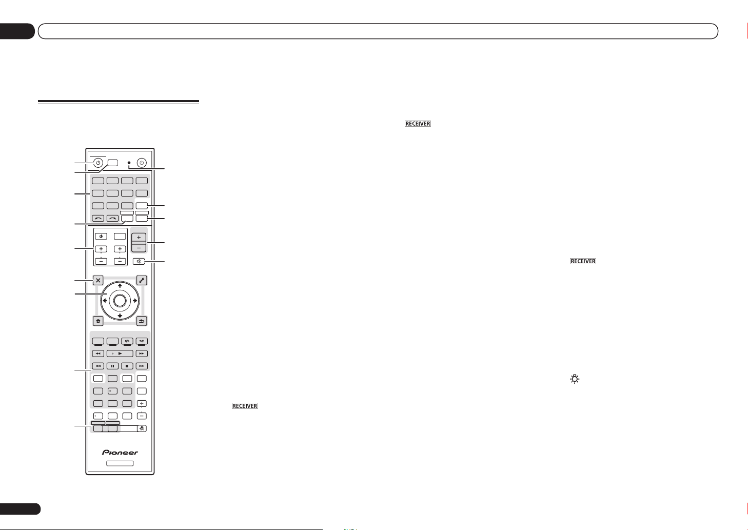
Remote control
This section explains how to operate the remote
control for the receiver.
MULTI
SOURCERECEIVER
1
2,3
4
5
6
7
8
9
10
OPERATION
RCU SETUP
BDR
BD DVD DVR
SAT
HMG
CDTV
USB OPTION
iPod
TUNER
SIRIUS
RECEIVER
TV CTRL
SELECT
INPUT
MASTER
VOLUME
INPUT
TV CONTROL
VOL
CH
AUDIO
PARAMETER
TOP MENU
BAND GUIDE
PRESET
CATEGORY
HOME
MENU
iPod CTRL
AUTO / ALC /
DIRECT
HDD DVD
TV
/
DTV MPX PQLS
1 32
SIGNAL SEL
CH LEVEL A.ATT DIMMER
D.ACCESS
/ CLR
ZONE 2 ZONE 3
LIST
TUNE
ENTER
TUNE
PGM
STEREO
PHASE
HDMI OUT
MCACC SLEEP
54 6
807 9
RECEIVER
TOOLS
MEMORY
STANDARD
CTRL STATUSTHX
3
CLASS
ENTER
MUTE
PARAMETER
RETURN
MENU
ADV SURR
AUDIO
HDMI
ADPT
VIDEO
T.EDIT
INFO
DISP
LIGHT
11
12
13
14
15
PRESET
CH
The remote has been conveniently color-coded
according to component control using the following system:
! White – Receiver control, TV control
! Blue – Other controls (See pages 30, 31, 33, 35
and 59.)
1 u RECEIVER
This switches between standby and on for this
receiver.
2 MULTI OPERATION
Use this button to perform multi operations
(page 58).
3 RCU SETUP
Use to input the preset code when making
remote control settings and to set the remote
control mode (page 56).
4 Input function buttons
Press to select control of other components
(page 56).
Use INPUT SELECT c/ d to select the input
function (page 30).
5 TV CTRL
Set the preset code of your TV’s manufacturer
when controlling the TV (page 56).
6 TV CONTROL buttons
These buttons are dedicated to control the TV
assigned to the TV CTRL button.
7 Receiver setting buttons
Press first to access:
! AUDIO PARAMETER – Use to access the
Audio options (page 50).
! VIDEO PARAMETER – Use to access the
Video options (page 52).
! HOME MENU – Use to access the Home
Menu (pages 26, 28, 47, 62 and 69).
! RETURN – Press to confirm and exit the
current menu screen.
8 i/j/k/l/ENTER
Use the arrow buttons when setting up your
surround sound system (see page 62) and the
Audio or Video options (page 50 or 52).
9 Receiver Control buttons
Press first to access:
! AUTO/ALC/DIRECT – Switches between
Auto Surround (page 37), Auto Level Control,
Optimum Surround mode and Stream Direct
mode (page 38).
! STEREO – Press to select stereo playback
mode (page 37).
! STANDARD – Press for Standard decoding
and to switch various modes (2 Pro Logic,
Neo:6, etc.) (page 37).
! ADV SURR – Use to switch between the
various surround modes (page 38).
! THX – Press to select a Home THX listening
mode (page 38).
! PHASE CTRL – Press to switch on/off Phase
Control (page 39).
On the VSX-53, Full Band Phase Control can
also be switched (page 39).
! STATUS – Press to check selected receiver
settings (page 55).
! PQLS – Press to select the PQLS setting
(page 48).
! HDMI OUT – Switch the HDMI output
terminal (page 54).
This function is only provided on the VSX-53.
It cannot be used on the VSX-52.
! SIGNAL SEL – Use to select an input signal
(page 39).
! MCACC – Press to switch between MCACC
presets (page 39).
! SLEEP – Use to put the receiver in sleep
mode and select the amount of time before
sleep (page 54).
! CH LEVEL – Press repeatedly to select a
channel, then use k/l to adjust the level
(page 70).
! A.ATT – Attenuates (lowers) the level of an
analog input signal to prevent distortion
(page 54).
! DIMMER – Dims or brightens the display
(page 54).
10 MULTI-ZONE select buttons
Switch to perform operations in ZONE 2 and
ZONE 3 (page 53).
ZONE 3 function is only provided on the VSX-53.
ZONE 3 button cannot be used on the VSX-52.
11 Remote control LED
Lights when a command is sent from the
remote control.
12 OPTION
The preset codes of desired devices can be
registered in the remote control and button
operations can be registered using the learning
mode.
13
Switches the remote to control the receiver
(used to select the white commands).
Switch to perform operations in the main zone.
Also use this button to set up surround sound.
14 MASTER VOLUME +/–
Use to set the listening volume.
15 MUTE
Mutes the sound or restores the sound if it has
been muted (adjusting the volume also restores
the sound).
16 LIGHT
Press to turn on/off the illumination for the
buttons.
The way the buttons light can be selected from
four modes (page 58).
En
8
Controls and displays
02
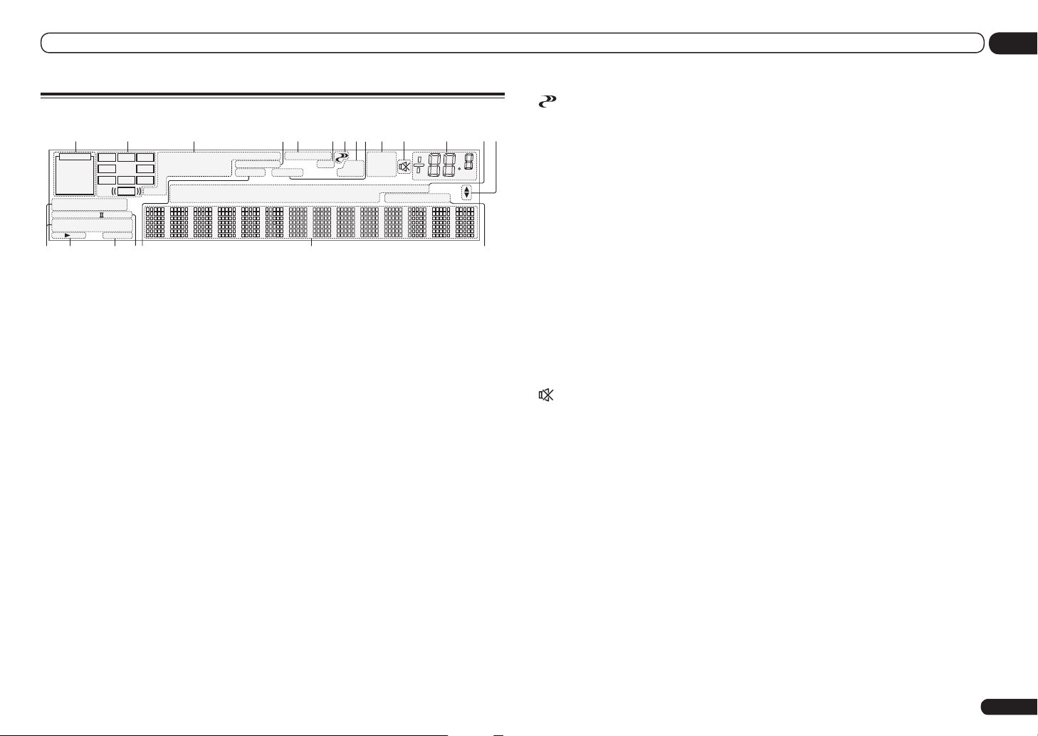
Display
21 3 8654 107 11 12 13
2
AUTO
HDMI
DIGITAL
ANALOG
AUTO SURROUND
STREAM DIRECT
2
PROLOGIC x
THX ADV.SURROUND
STANDARD
SP AB
6
L C R
SL SR
XL XR
XC
LFE
Neo:6
SLEEP
DIGITAL PLUS
2
TrueHD
DTS HD ES 96/24
CD
MSTR
1 Signal indicators
Light to indicate the currently selected input
signal. AUTO lights when the receiver is set to
select the input signal automatically (page 39).
2 Program format indicators
Light to indicate the channels to which digital
signals are being input.
! L/R – Left front/Right front channel
! C – Center channel
! SL/SR – Left surround/Right surround
channel
! LFE – Low frequency effects channel (the (( ))
indicators light when an LFE signal is being
input)
! XL/XR – Two channels other than the ones
above
! XC – Either one channel other than the ones
above, the mono surround channel or matrix
encode flag
3 Digital format indicators
Light when a signal encoded in the corresponding format is detected.
! 2 DIGITAL – Lights with Dolby Digital
decoding.
! 2 DIGITAL PLUS – Lights with Dolby Digital
Plus decoding.
! 2 TrueHD – Lights with Dolby TrueHD
decoding.
! DTS – Lights with DTS decoding.
! DTS HD – Lights with DTS-HD decoding.
DSD PCM
MULTI-ZONE
S.RTRV SOUND UP MIX
TUNER
SIRIUS
iPod
9
FULL BAND
PQLS
TV
DVD
DVR
BD
19 2015 16 17 18
ALC
ATT
OVER
VIDEO HMG
HDMI
TUNED
STEREO
MONO
[ 2 ]
USB
[ 3 ]
dB
[ 4 ]
! 96/24 – Lights with DTS 96/24 decoding.
! DSD PCM – Light during DSD (Direct Stream
Digital) to PCM conversion with SACDs.
! PCM – Lights during playback of PCM
signals.
! MSTR – Lights during playback of DTS-HD
Master Audio signals.
4 MULTI-ZONE
Lights when the MULTI-ZONE feature is active
(page 53).
5 FULL BAND
VSX-53 only: Lights when the Full Band Phase
Control is switched on (page 39).
6 Listening mode indicators
! AUTO SURROUND – Lights when the Auto
Surround feature is switched on (page 37).
! ALC – Lights when the ALC (Auto level
control) mode is selected (page 37).
! STREAM DIRECT – Lights when Direct/Pure
Direct is selected (page 38).
! ADV.SURROUND – Lights when one of
the Advanced Surround modes has been
selected (page 38).
! STANDARD – Lights when one of the
Standard Surround modes is switched on
(page 37).
! THX – Lights when one of the Home THX
modes is selected (page 38).
7 (PHASE CONTROL)
Lights when the Phase Control (page 39) or Full
Band Phase Control (page 39) is switched on.
14
Full Band Phase Control is only apply to the
VSX-53.
8 Analog signal indicators
Light to indicate reducing the level of an analog
signal (page 54).
9 SOUND
Lights when the DIALOG E (Dialog
Enhancement) or TONE (tone controls) features
is selected (page 50).
10 Tuner indicators
! TUNED – Lights when a broadcast is being
received.
! STEREO – Lights when a stereo FM
broadcast is being received in auto stereo
mode.
! MONO – Lights when the mono mode is set
using MPX.
11
Lights when the sound is muted.
12 Master volume level
Shows the overall volume level.
“---” indicates the minimum level, and “+12dB”
indicates the maximum level.
13 Input function indicators
Light to indicate the input function you have
selected.
14 Scroll indicators
Light when there are more selectable items
when making the various settings.
15 Speaker indicators
Lights to indicate the current speaker system
using SPEAKERS (page 53).
16 SLEEP
Lights when the receiver is in sleep mode (page
54).
17 Matrix decoding format indicators
! 2PRO LOGIC IIx – This lights to indicate 2
Pro Logic II / 2 Pro Logic IIx decoding (page
37).
! Neo:6 – When one of the Neo:6 modes of the
receiver is on, this lights to indicate Neo:6
processing (page 37).
18 S.RTRV
Lights when the Auto Sound Retriever function
is active (page 50).
19 Character display
Displays various system information.
20 Remote control mode indicator
Lights to indicate the receiver’s remote control
mode setting. (Not displayed when set to 1.)
(page 74)
En
9
02 Controls and displays
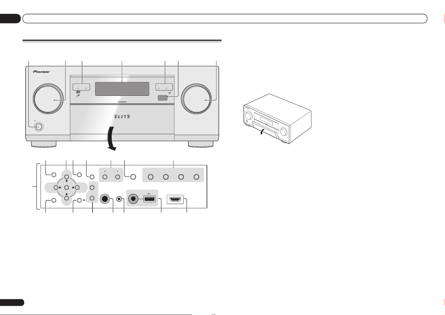
Front panel
1 2 43 5 6
ADVANCED
MCACC
FL OFF
INPUT
SELECTOR
STANDBY/ON
8 9 10 11 12 13 14
TUNE
ENTER
TUNE
VIDEO
PARAMETER
AUTO SURR/A LC/
MCACC
SETUP MIC
iPod iPhone iPad
STREAM DIRE CT HOME THX
DIRECT CONTROL
iPod iPhone iPad
BAND
MULTI-ZONE
CONTROL ON/OFF
PHONES
SPEAKERS
PRESETPRESET
TUNER EDIT
AUDIO
PARAMETER
7
HOME MENU RETURN
15 16 17 1918 20 21
1 u STANDBY/ON
This switches between standby and on for this
receiver.
2 INPUT SELECTOR dial
Use to select an input function.
3 Indicators
! ADVANCED MCACC – Lights when EQ is
set to ON in the AUDIO PARAMETER menu
(page 50).
En
10
! FL OFF – Lights when “off” (nothing
displayed) is selected with the display’s
dimmer adjustment (page 54).
! HDMI – Blinks when connecting an HDMI-
equipped component; lights when the
component is connected (page 17).
! iPod iPhone iPad – Lights to indicate iPod/
iPhone/iPad is connected (page 23).
4 Character display
See Display on page 9 .
USB
5V 2.1 A
3
iPod iPhone iPadHDMI
ADVANCED
SURROUND
STANDARD
SURROUND
HDMI 3 INPUT
MASTER
VOLUME
5 Remote sensor
Receives the signals from the remote control
(page 7).
6 MASTER VOLUME dial
7 Front panel controls
To access the front panel controls, catch the
sides of the door with your fingers and pull
forward.
INPUT
SELECTOR
STANDBY/ON
MASTER
VOLUME
8 AUDIO PARAMETER
Use to access the Audio options (page 50).
9 i/j/k/l (TUNE/PRESET) /ENTER
Use the arrow buttons when setting up your
Home Menu. Use TUNE i/j to find radio fre-
quencies and use PRESET k/l to find preset
stations (page 33).
10 VIDEO PARAMETER
Use to access the Video options (page 52).
11 SPEAKERS
Use to change the speaker terminal (page 53).
12 MULTI-ZONE controls
If you’ve made MULTI-ZONE connections (page
21) use these controls to control the sub zone
from the main zone (page 53).
13 iPod iPhone iPad DIRECT CONTROL
Change the receiver’s input to the iPod and
enable iPod operations on the iPod (page 31).
14 Listening mode buttons
! AUTO SURR/ALC/STREAM DIRECT –
Switches between Auto Surround (page 37),
Auto Level Control, Optimum Surround mode
and Stream Direct mode (page 38).
! STANDARD SURROUND – Press for
Standard decoding and to switch various
modes (2 Pro Logic, Neo:6, Stereo etc.)
(page 37).
! ADVANCED SURROUND – Use to switch
between the various surround modes (page
38).
! HOME THX – Press to select a Home THX
listening mode (page 38).
15 HOME MENU
Use to access the Home Menu (page 26, 28, 47,
62 and 69).
16 RETURN
Press to confirm and exit the current menu
screen.
17 TUNER controls
! BAND – Switches between AM and FM radio
bands (page 33).
! TUNER EDIT – Use with TUNE i/j, PRESET
k/l and ENTER to memorize and name
stations for recall (page 33).
18 PHONES jack
Use to connect headphones. When the headphones are connected, there is no sound output
from the speakers.
19 MCACC SETUP MIC jack
Use to connect the supplied microphone (page
26).
20 iPod iPhone iPad USB terminals
Use to connect your Apple iPod/iPhone/iPad as
an audio and video source (page 23), or connect a USB device for audio and photo playback
(page 23).
21 HDMI input connector
Use for connection to a compatible HDMI
device (Video camera, etc.) (page 23).
Connecting your equipment
ANTENN
O
03
Connecting your equipment
Connecting your equipment
This receiver provides you with many connection possibilities, but it doesn’t have to be difficult. This
chapter explains the kinds of components you can connect to make up your home theater system.
CAUTION
Before making or changing the connections, switch off the power and disconnect the power cord
from the power outlet. Plugging in should be the final step.
Important
Illustration shows the VSX-53, however connections for the VSX-52 are the same except where
noted.
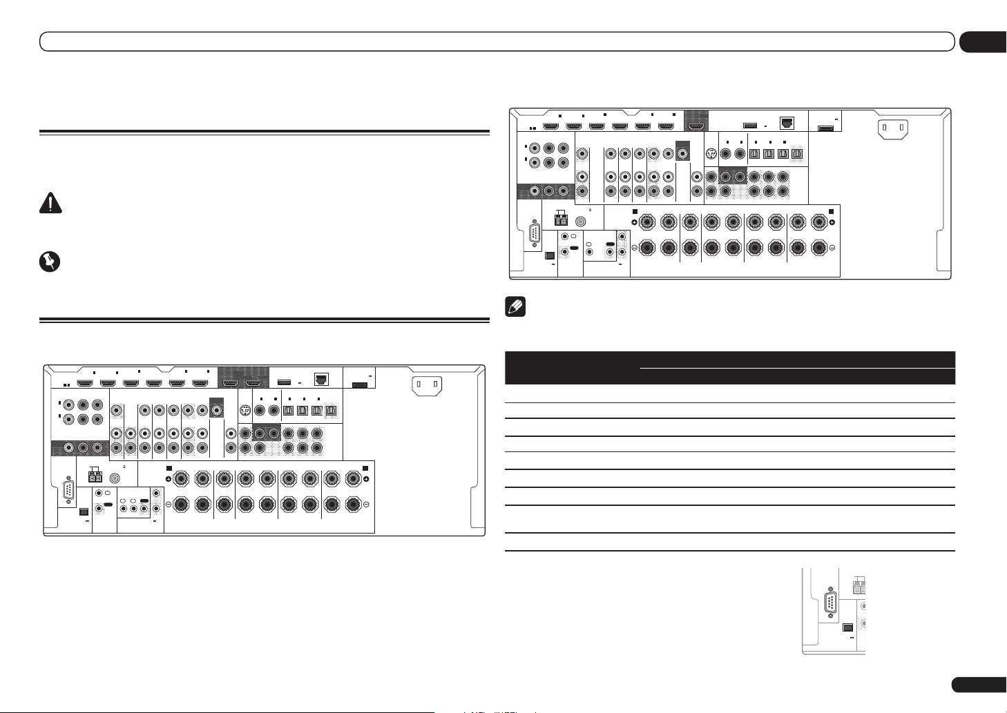
Rear panel
VSX-53
ASSIGNABLE
MONITOR
IN
(
DVD
IN
(
DVR/
BDR
OUT
HDMI
ASSIGNABLE
1 6
Y PBP
1
)
2
)
RS-232C
(
OUTPUT 5 V
150 mA MAX
COMPONENT VIDEO
AM LOOP
EXTENSION
IN1IN
R
ANTENNA
CONTROL
)
ZONE 2
FM UNBAL 75
IN
OUT
2
ZONE 3
OUT
1IN2
IN
4
IN
(VIDEO)
IR
(OUTPUT 12 V
TOTAL 150 mA MAX)
12 V TRIGGER
DVD
IN IN IN IN
SPEAKERS
OUT
5
6
IN
IN
(DVD)
BD IN
TV/SAT VIDEO
(DVR/BDR)
MONITOR
OUT
DVR/BDR
OUTOUT
AUDIO
FRONT CENTER
R L R L
A
1
2
VIDEO
CD
IN
OUT 1
(CONTROL)
SIRIUS
FRONT
IN
SURROUND
OUT 2
COAXIAL
ASSIGNABLE
IN1IN
)
DVD
SUBWOOFER
1 2
CENTER
DC OUTPUT
for WIRELESS LAN
OPTICAL
ASSIGNABLE
2
IN1IN2IN3OUT
(CD)(
SURROUND SURR BACK
SURROUND BACK
R
(
5 V
0.6 A MAX
)
OUTPUT
(
DVR/BDR)(TV/SAT
)
(
VIDEO
FH / FW
(
)
Single
L
LAN
(
10/100
)
PRE OUT
L
R
(
)
FRONT HEIGHT / FRONT WIDE /
Single
R L
ADAPTER PORT
)
(
OUTPUT 5 V
0.1 A MAX
AC IN
)
B
VSX-52
ASSIGNABLE
IN
(
IN
(
BDR
MONITOR
OUT
DVD
DVR/
HDMI
ASSIGNABLE
1 6
Y PBP
1
)
2
)
RS-232C
(
OUTPUT 5 V
150 mA MAX
COMPONENT VIDEO
ANTENNA
AM LOOP
)
EXTENSION
IN1IN
R
CONTROL
ZONE 2
FM UNBAL 75
IN
OUT
2
IN
4
IN
(VIDEO)
IR
(OUTPUT 12 V
TOTAL 150 mA MAX)
12 V TRIGGER
DVD
IN IN IN IN
SPEAKERS
OUT
5
6
IN
IN
(DVD)
BD IN
TV/SAT VIDEO
(DVR/BDR)
MONITOR
OUT
DVR/BDR
OUTOUT
AUDIO
FRONT CENTER
R L R L
A
1
2
VIDEO
OUT
DC OUTPUT
for WIRELESS LAN
(
OUTPUT
5 V
COAXIAL
ASSIGNABLE
IN1IN
)
DVD
SUBWOOFER
1 2
CENTER
0.6 A MAX
OPTICAL
ASSIGNABLE
2
IN1IN2IN3OUT
(CD)(
)
SURROUND SURR BACK
SURROUND BACK
R
(
DVR/BDR)(TV/SAT
SIRIUS
IN
CD
IN
FRONT
SURROUND
)
(
VIDEO
FH / FW
(
)
Single
(
Single
L
ADAPTER PORT
LAN
(
)
10/100
)
PRE OUT
L
R
)
FRONT HEIGHT / FRONT WIDE /
R L
(
OUTPUT 5 V
0.1 A MAX
AC IN
)
B
Note
! The input functions below are assigned by default to the receiver’s different input terminals. Refer to
The Input Setup menu on page 28 to change the assignments if other connections are used.
Input function
BD
HDMI Digital Component
(BD)
DVD IN 5 COAX-1 IN 1
TV/SAT OPT-1
DVR/BDR IN 6 OPT-2 IN 2
VIDEO IN 4 OPT-3
HDMI 1 IN 1
HDMI 2 IN 2
HDMI 3
(front panel)
IN 3
CD COAX-2
Input Terminals
! The CU-RF100 omni-directional remote control
(separately sold) can be connected to the
RS-232C
AM LOOP
RS-232C and EXTENSION terminals. Using
the CU-RF100 lets you display the receiver’s
display information on the remote control
display in your hands and operate it without
worrying about obstacles or the direction in
(
OUTPUT 5 V
150 mA MAX
EXTENSION
C
)
which the remote control is pointing.
En
11
03 Connecting your equipment
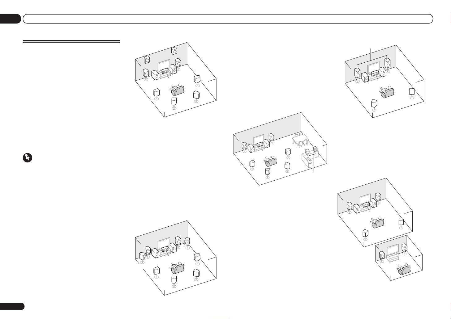
Determining the speakers’
application
This unit permits you to build various surround
systems, in accordance with the number of
speakers you have.
! Be sure to connect speakers to the front left
and right channels (L and R).
! It is also possible to only connect one of the
surround back speakers (SB) or neither.
! If you have two subwoofers, the second
subwoofer can be connected to the
SUBWOOFER 2 terminal. Connecting two
subwoofers increases the bass sound to
achieve more powerful sound reproduction. In
this case, the same sound is output from the
two subwoofers.
Choose one from Plans [A] to [E] below.
Important
! The Speaker System setting must be made if
you use any of the connections shown below
other than [A] (see Speaker system setting on
page 69 ).
! Sound does not come through simultaneously
from the front height, front wide, speaker B
and surround back speakers. Output speakers
are different depending on the input signal or
listening mode.
[A] 7.2 channel surround system (Front
height)
*Default setting
! Speaker System setting: Normal(SB/FH)
FHR
FHL
L
SW 1
SL
R
SW
2
C
SBL
SR
SBR
A 7.2 ch surround system connects the left and
right front speakers (L/R), the center speaker
(C), the left and right front height speakers
(FHL/FHR), the left and right surround speakers (SL/SR), the left and right surround back
speakers (SBL/SBR), and the subwoofers (SW 1/
SW 2).
It is not possible to produce sound simultaneously from the front height or front wide speakers and the surround back speakers.
This surround system produces a more true-tolife sound from above.
[B] 7.2 channel surround system (Front
wide)
! Speaker System setting: Normal(SB/FW)
R
SW
2
SBL
FWR
SR
SBR
FWL
L
C
SW 1
SL
This plan replaces the left and right front height
speakers shown in [A] with the left and right
front wide speakers (FWL/FWR).
It is not possible to produce sound simultaneously from the front height or front wide speakers and the surround back speakers.
This surround system produces a true-to-life
sound over a wider area.
[C] 7.2 channel surround system & Speaker
B connection
! Speaker System setting: Speaker B
R
L
SW
SW 2
C
1
SL
SBL
SR
SBR
R
L
Speaker B
With these connections you can simultaneously
enjoy 5.2-channel surround sound in the main
zone with stereo playback of the same sound
on the B speakers. The same connections also
allow for 7.2-channel surround sound in the
main zone when not using the B speakers.
[D] 5.2 channel surround system & Front
Bi-amping connection (High quality
surround)
! Speaker System setting: Front Bi-Amp
Bi-amping connection of the front speakers for
high sound quality with 5.2-channel surround
sound.
Front Bi-Amp
R
L
SW
SW 2
C
1
SR
SL
[E] 5.2 channel surround system & ZONE 2
connection (Multi Zone)
! Speaker System setting: ZONE 2
With these connections you can simultaneously
enjoy 5.2-channel surround sound in the main
zone with stereo playback on another component in ZONE 2. (The selection of input devices
is limited.)
R
L
SW 2
C
1
SW
SL
ZONE 2
Main zone
SR
Sub zone
R
L
12
En
Connecting your equipment
03
Other speaker connections
! Your favorite speaker connections can be
selected even if you have fewer than 5.2
speakers (except front left/right speakers).
! When not connecting a subwoofer, connect
speakers with low frequency reproduction
capabilities to the front channel. (The
subwoofer’s low frequency component
is played from the front speakers, so the
speakers could be damaged.)
! After connecting, be sure to conduct the
Full Auto MCACC (speaker environment
setting) procedure. See Automatically
conducting optimum sound tuning (Full Auto
MCACC) on page 26 .
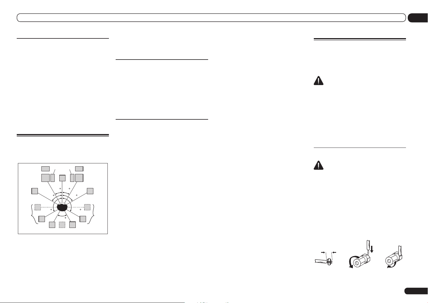
Placing the speakers
Refer to the chart below for placement of the
speakers you intend to connect.
SW
FHL
L
FWL
1 SW 2
C
30 30
60
SL
! Place the surround speakers at 120º from
the center. If you, (1) use the surround
back speaker, and, (2) don’t use the front
height speakers / front wide speakers, we
recommend placing the surround speaker
right beside you.
! If you intend to connect only one surround
back speaker, place it directly behind you.
120 120
60
SBL
SB
FHR
R
FWR
60
SR
SBR
! Place the left and right front height speakers
at least one meter (3.3 ft.) directly above the
left and right front speakers.
THX speaker system setup
If you are using a THX certified subwoofer, use
the THX INPUT jack on the subwoofer (if your
subwoofer has one) or switch the filter position
to THX on your subwoofer.
See also THX Audio Setting on page 71 to make
the settings that will give you the best sound
experience when using the Home THX modes
(page 38).
Some tips for improving sound
quality
Where you put your speakers in the room has
a big effect on the quality of the sound. The
following guidelines should help you to get the
best sound from your system.
! The subwoofer can be placed on the floor.
Ideally, the other speakers should be at about
ear-level when you’re listening to them.
Putting the speakers on the floor (except the
subwoofer), or mounting them very high on a
wall is not recommended.
! For the best stereo effect, place the front
speakers 2 m to 3 m (6 ft. to 9 ft.) apart, at
equal distance from the TV.
! If you’re going to place speakers around your
CRT TV, use shielded speakers or place the
speakers at a sufficient distance from your
CRT TV.
! If you’re using a center speaker, place the
front speakers at a wider angle. If not, place
them at a narrower angle.
! Place the center speaker above or below the
TV so that the sound of the center channel is
localized at the TV screen. Also, make sure the
center speaker does not cross the line formed
by the leading edge of the front left and right
speakers.
! It is best to angle the speakers towards the
listening position. The angle depends on
the size of the room. Use less of an angle for
bigger rooms.
! Surround and surround back speakers
should be positioned 60 cm to 90 cm (2 ft. to
3 ft.) higher than your ears and tilted slightly
downward. Make sure the speakers don’t
face each other. For DVD-Audio, the speakers
should be more directly behind the listener
than for home theater playback.
! Try not to place the surround speakers farther
away from the listening position than the front
and center speakers. Doing so can weaken the
surround sound effect.
Connecting the speakers
Each speaker connection on the receiver comprises a positive (+) and negative (–) terminal.
Make sure to match these up with the terminals
on the speakers themselves.
CAUTION
! These speaker terminals carry HAZARDOUS
LIVE voltage. To prevent the risk of electric
shock when connecting or disconnecting the
speaker cables, disconnect the power cord
before touching any uninsulated parts.
! Make sure that all the bare speaker wire is
twisted together and inserted fully into the
speaker terminal. If any of the bare speaker
wire touches the back panel it may cause the
power to cut off as a safety measure.
Bare wire connections
CAUTION
Make sure that all speakers are securely
installed. This not only improves sound quality,
but also reduces the risk of damage or injury
resulting from speakers being knocked over or
falling in the event of external shocks such as
earthquakes.
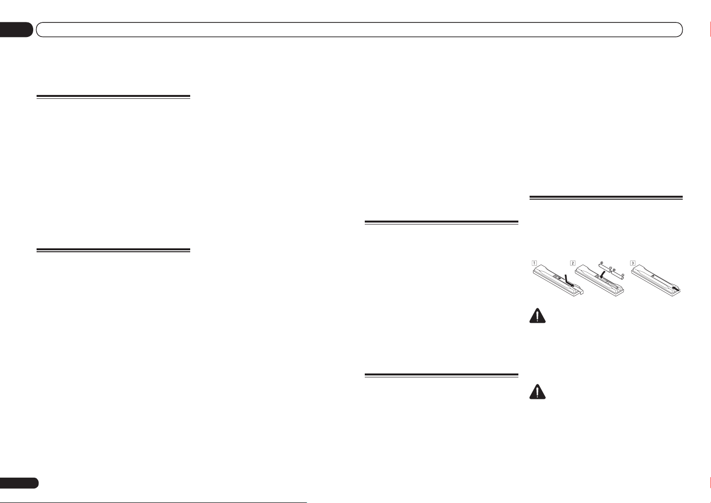
1 Twist exposed wire strands together.
2 Loosen terminal and insert exposed
wire.
3 Tighten terminal.
1 2 3
10 mm (3/8 in.)
En
13
03 Connecting your equipment
Note
! Please refer to the manual that came with
your speakers for details on how to connect
the other end of the speaker cables to your
speakers.
! Use an RCA cable to connect the subwoofer.
It is not possible to connect using speaker
cables.
! If you have two subwoofers, the second
subwoofer can be connected to the
SUBWOOFER 2 terminal. Connecting two
subwoofers increases the bass sound to
achieve more powerful sound reproduction. In
this case, the same sound is output from the
two subwoofers.
Banana plug connections
If you want to use speaker cables terminated
with banana plugs, screw the speaker terminal
fully shut, then plug the banana plug into the
end of the speaker terminal.
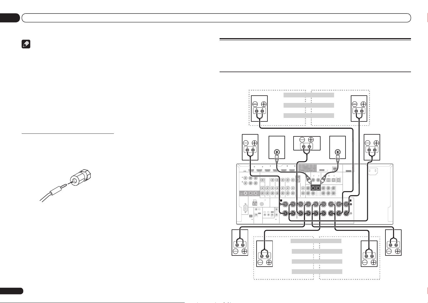
Installing your speaker system
At the very least, front left and right speakers only are necessary. Note that your main surround
speakers should always be connected as a pair, but you can connect just one surround back
speaker if you like (it must be connected to the left surround back terminal).
Standard surround connection
The front height terminals can also be used for the front wide and Speaker B speakers.
Front right
HDMI
ASSIGNABLE
1 6
ASSIGNABLE
Y PBP
1
IN
(
)
DVD
2
IN
(
DVR/
)
BDR
MONITOR
OUT
RS-232C
(
OUTPUT 5 V
150 mA MAX
EXTENSION
IN1IN
COMPONENT VIDEO
ANTENNA
AM LOOP
)
Front height right
Front height setting
Front wide setting
Front wide right
Speaker B - right Speaker B - left
Speaker B setting
Center Subwoofer 2Subwoofer 1
LINE LEVEL
INPUT
R
CONTROL
FM UNBAL 75
IN
OUT
ZONE 2
2
ZONE 3
IN
IN
(VIDEO)
OUT
IR
1IN2
(OUTPUT 12 V
TOTAL 150 mA MAX)
12 V TRIGGER
4
TV/SAT VIDEO
DVD
IN IN IN IN
SPEAKERS
OUT
6
IN5IN
(DVD)
(DVR/BDR)
BD IN
MONITOR
OUT
DVR/BDR
OUTOUT
AUDIO
FRONT CENTER
R L R L
A
1
2
OUT 1
(CONTROL)
SIRIUS
IN
VIDEO
CD
IN
FRONT
COAXIAL
1 2
CENTER
SURROUND
OUT 2
ASSIGNABLE
IN1IN
DVD
SUBWOOFER
)
Front height left
DC OUTPUT
for WIRELESS LAN
(
OUTPUT
5 V
0.6 A MAX
OPTICAL
ASSIGNABLE
2
IN1IN2IN3OUT
(CD)(
(
)
DVR/BDR)(TV/SAT
SURROUND SURR BACK
SURROUND BACK
R L
Front wide left
LINE LEVEL
INPUT
ADAPTER PORT
LAN
(
)
10/100
)
(
)
VIDEO
FH / FW
PRE OUT
(
)
Single
L
R
(
)
FRONT HEIGHT / FRONT WIDE /
Single
R L
(
OUTPUT 5 V
0.1 A MAX
Front left
AC IN
)
B
14
En
Surround right
The surround back terminals can also be used for ZONE 2.
Not connected Not connected
Not connected Surround back
Surround back right Surround back left
ZONE 2 - Right ZONE 2 - Left
5.2 ch surround setting
6.2 ch surround setting
7.2 ch surround setting
ZONE 2 setting
Surround left
Connecting your equipment
03
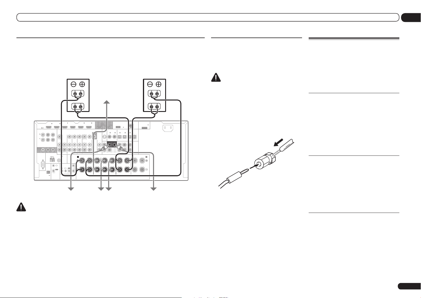
Bi-amping your speakers
Bi-amping is when you connect the high frequency driver and low frequency driver of your speakers
to different amplifiers for better crossover performance. Your speakers must be bi-ampable to do
this (having separate terminals for high and low) and the sound improvement will depend on the
kind of speakers you’re using.
LAN
(
)
10/100
)
PRE OUT
L
R
)
FRONT HEIGHT / FRONT WIDE /
R L
ADAPTER PORT
(
OUTPUT 5 V
0.1 A MAX
Front left
High
Low
)
B
AC IN
Bi-amp compatible
speaker
Front right
Bi-amp compatible
speaker
IN1IN
HDMI
ASSIGNABLE
1 6
ASSIGNABLE
COMPONENT VIDEO
Y PBP
1
IN
(
)
DVD
2
IN
(
DVR/
)
BDR
MONITOR
OUT
ANTENNA
RS-232C
AM LOOP
(
OUTPUT 5 V
)
150 mA MAX
EXTENSION
R
ZONE 2
FM UNBAL 75
IN
OUT
CONTROL
Subwoofer 1 Subwoofer 2
2
IN
IN
(VIDEO)
ZONE 3
OUT
IR
1IN2
(OUTPUT 12 V
TOTAL 150 mA MAX)
12 V TRIGGER
High
Low
4
TV/SAT VIDEO
DVD
IN IN IN IN
SPEAKERS
OUT
6
IN5IN
(DVD)
(DVR/BDR)
BD IN
MONITOR
OUT
DVR/BDR
OUTOUT
AUDIO
FRONT CENTER
R L R L
A
1
2
Surround right Surround left
VIDEO
OUT 1
(CONTROL)
CD
IN
Center
SIRIUS
IN
FRONT
SURROUND
OUT 2
COAXIAL
ASSIGNABLE
IN1IN
)
DVD
SUBWOOFER
1 2
CENTER
DC OUTPUT
for WIRELESS LAN
OPTICAL
ASSIGNABLE
2
IN1IN2IN3OUT
(CD)(
SURROUND SURR BACK
SURROUND BACK
R L
(
OUTPUT
5 V
)
0.6 A MAX
(
)
(
DVR/BDR)(TV/SAT
VIDEO
FH / FW
(
)
Single
(
Single
CAUTION
! Most speakers with both High and Low terminals have two metal plates that connect the High
to the Low terminals. These must be removed when you are bi-amping the speakers or you could
severely damage the amplifier. See your speaker manual for more information.
! If your speakers have a removable crossover network, make sure you do not remove it for bi-amping.
Doing so may damage your speakers.
Bi-wiring your speakers
Your speakers can also be bi-wired if they support bi-amping.
! With these connections, the Speaker System
setting makes no difference.
CAUTION
! Don’t connect different speakers from the
same terminal in this way.
! When bi-wiring as well, heed the cautions for
bi-amping shown above.
% To bi-wire a speaker, connect two
speaker cords to the speaker terminal on
the receiver.
Using a banana plug for the second connection
is recommended.
Selecting the Speaker system
The front height terminals can be used for front
wide and Speaker B connections, in addition to
for the front height speakers. Also, the surround
back terminals can be used for bi-amping and
ZONE 2 connections, in addition to for the surround back speakers. Make this setting according to the application.
Front height setup
*Default setting
1 Connect a pair of speakers to the front
height speaker terminals.
See Standard surround connection on page 14 .
2 If necessary, select ‘Normal(SB/FH)’
from the Speaker System menu.
See Speaker system setting on page 69 to do
this.
Front wide setup
1 Connect a pair of speakers to the front
height speaker terminals.
See Standard surround connection on page 14 .
2 Select ‘Normal(SB/FW)’ from the
Speaker System menu.
See Speaker system setting on page 69 to do
this.
Speaker B setup
You can listen to stereo playback in another
room.
1 Connect a pair of speakers to the front
height speaker terminals.
See Standard surround connection on page 14 .
2 Select ‘Speaker B’ from the
Speaker System menu.
See Speaker system setting on page 69 to do
this.
En
15
03 Connecting your equipment
Bi-Amping setup
Bi-amping connection of the front speakers for
high sound quality with 5.2-channel surround
sound.
1 Connect bi-amp compatible speakers
to the front and surround back speaker
terminals.
See Bi-amping your speakers on page 15 .
2 Select ‘Front Bi-Amp’ from the
Speaker System menu.
See Speaker system setting on page 69 to do
this.
ZONE 2 setup
With these connections you can simultaneously
enjoy 5.2-channel surround sound in the main
zone with stereo playback on another component in ZONE 2.
1 Connect a pair of speakers to the
surround back speaker terminals.
See Standard surround connection on page 14 .
2 Select ‘ZONE 2’ from the
Speaker System menu.
See Speaker system setting on page 69 to do
this.
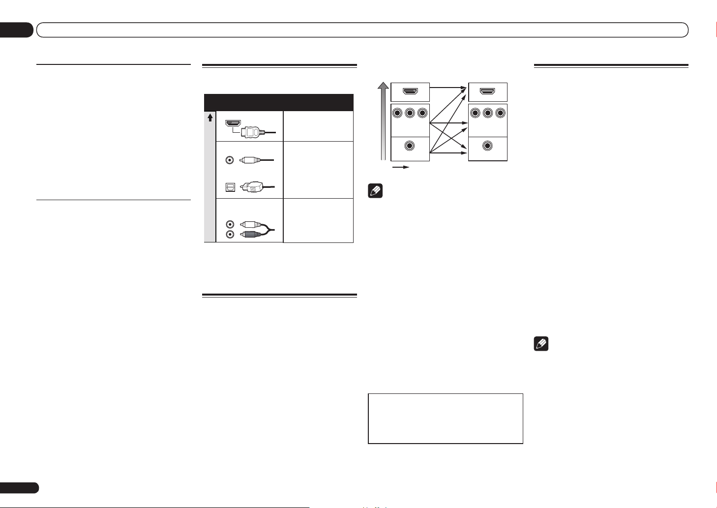
About the audio connection
Types of cables and
terminals
HDMI HD audio
Digital (Coaxial) Conventional digital audio
Digital (Optical)
Sound signal priority
RCA (Analog)
(White/Red)
! With an HDMI cable, video and audio signals
can be transferred in high quality over a single
cable.
Transferable audio
signals
Conventional analog audio
About the video converter
The video converter ensures that all video
sources are output through all of the MONITOR
VIDEO OUT jacks. The only exception is HDMI:
since this resolution cannot be downsampled,
you must connect your monitor/TV to the
receiver’s HDMI output when connecting this
video source.
If several video components are assigned to
the same input function (see The Input Setup
menu on page 28 ), the converter gives priority
to HDMI, component, then composite (in that
order).
Terminal for connection with
source device
HDMI IN HDMI OUT
Y PBP
High picture quality
R
COMPONENT
VIDEO IN
VIDEO IN
Video signals can be output
Terminal for connection
with TV monitor
B
P
Y
P
MONITOR OUT
VIDEO
MONITOR OUT
R
COMPONENT VIDEO
Note
! If the video signal does not appear on your
TV, try adjusting the resolution settings on
your component or display. Note that some
components (such as video game units) have
resolutions that may not be converted. In this
case, try switching Digital Video Conversion
(in Setting the Video options on page 52 ) OFF.
! The signal input resolutions that can be
converted from the component video input
for the HDMI output are 480i/576i, 480p/576p,
720p and 1080i. 1080p signals cannot be
converted.
! Only signals with an input resolution
of 480i/576i can be converted from the
component video input for the composite
MONITOR OUT terminals.
! For optimal video performance, THX
recommends switching Digital Video
Conversion (in Setting the Video options on
page 52 ) OFF.
This item incorporates copy protection technology that is protected by U.S. patents and other
intellectual property rights of Rovi Corporation.
Reverse engineering and disassembly are
prohibited.
About HDMI
The HDMI connection transfers uncompressed
digital video, as well as almost every kind of
digital audio.
This receiver incorporates High-Definition
Multimedia Interface (HDMI®) technology.
This receiver supports the functions described
below through HDMI connections.
! Digital transfer of uncompressed video
(contents protected by HDCP (1080p/24,
1080p/60, etc.))
! 3D signal transfer
! Deep Color signal transfer
! x.v.Color signal transfer
! ARC (Audio Return Channel)
! Input of multi-channel linear PCM digital
audio signals (192 kHz or less) for up to 8
channels
! Input of the following digital audio formats:
— Dolby Digital, Dolby Digital Plus, DTS, High
bitrate audio (Dolby TrueHD, DTS-HD Master
Audio, DTS-HD High Resolution Audio),
DVD-Audio, CD, SACD (DSD signal), Video
CD, Super VCD
! Synchronized operation with components
using the Control with HDMI function (see
Control with HDMI function on page 47 )
Note
! An HDMI connection can only be made
with DVI-equipped components compatible
with both DVI and High Bandwidth Digital
Content Protection (HDCP). If you choose to
connect to a DVI connector, you will need a
separate adaptor (DVIdHDMI) to do so. A DVI
connection, however, does not support audio
signals. Consult your local audio dealer for
more information.
16
En
Connecting your equipment
U
E
03
! If you connect a component that
is not compatible with HDCP, an
HDCP ERROR message is displayed on the
front panel display. Some components that
are compatible with HDCP still cause this
message to be displayed, but so long as there
is no problem with displaying video this is not
a malfunction.
! Depending on the component you have
connected, using a DVI connection may result
in unreliable signal transfers.
! This receiver supports SACD, Dolby Digital
Plus, Dolby TrueHD and DTS-HD Master
Audio. To take advantage of these formats,
however, make sure that the component
connected to this receiver also supports the
corresponding format.
! Use a High Speed HDMI® cable. If an HDMI
cable other than a High Speed HDMI® cable is
used, it may not work properly.
! When an HDMI cable with a built-in equalizer
is connected, it may not operate properly.
! Signal transfer is only possible when
connected to a compatible component.
! HDMI format digital audio transmissions
require a longer time to be recognized. Due to
this, interruption in the audio may occur when
switching between audio formats or beginning
playback.
! Turning on/off the device connected to this
unit’s HDMI OUT terminal during playback,
or disconnecting/connecting the HDMI
cable during playback, may cause noise or
interrupted audio.
HDMI, the HDMI logo and High-Definition
Multimedia Interface are trademarks or registered trademarks of HDMI Licensing, LLC in the
United States and other countries.
“x.v.Color” and are trademarks of Sony Corporation.
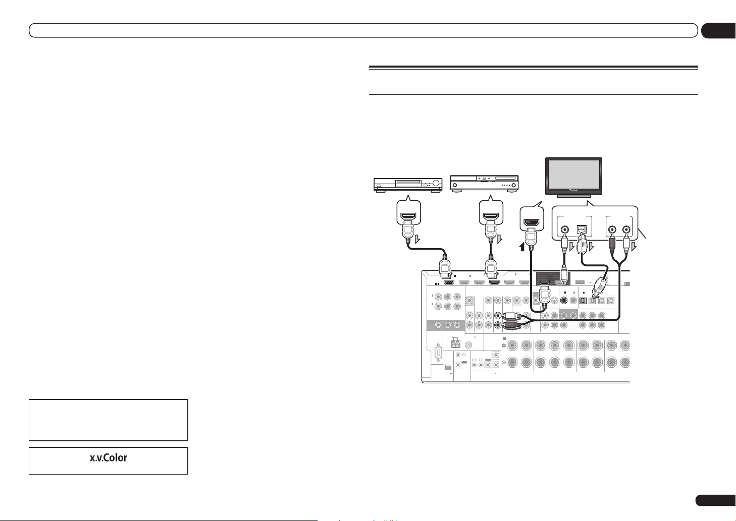
Connecting your TV and playback components
Connecting using HDMI
If you have an HDMI or DVI (with HDCP) equipped component (Blu-ray Disc player (BD), etc.), you
can connect it to this receiver using a commercially available HDMI cable.
If the TV and playback components support the Control with HDMI feature, the convenient Control
with HDMI functions can be used (see Control with HDMI function on page 47 ).
ASSIGNABLE
MONITOR
IN
(
DVD
IN
(
DVR/
BDR
OUT
HDMI
ASSIGNABLE
1
)
2
)
RS-232C
1 6
COMPONENT VIDEO
Y PBP
AM LOOP
(
OUTPUT 5 V
150 mA MAX
EXTENSION
HDMI/DVI-compatible
Blu-ray Disc player
4
IN
2
IN1IN
(VIDEO)
R
DVD
ZONE 2
ZONE 3
IN IN IN IN
OUT
ANTENNA
FM UNBAL 75
SPEAKERS
IR
IN
OUT
1IN2
IN
OUT
(OUTPUT 12 V
CONTROL
)
TOTAL 150 mA MAX)
12 V TRIGGER
HDMI IN
6
IN5IN
(DVD)
(DVR/BDR)
BD IN
MONITOR
OUT
VIDEO
DVR/BDR
OUTOUT
AUDIO
FRONT CENTER
CD
IN
TV/SAT VIDEO
R L R LRR
A
1
2
OUT 1
(CONTROL)
SIRIUS
FRONT
IN
SURROUND
DIGITAL OUT
COAXIAL OPTICAL
DC OUTPUT
for WIRELESS LAN
OUT 2
COAXIAL
ASSIGNABLE
2
IN1IN
(CD)(
)
DVD
SUBWOOFER
SURROUND SURR BACK
1 2
CENTER
Select one
(
OUTPUT
5 V
)
0.6 A MAX
OPTICAL
ASSIGNABLE
IN1IN2IN3OUT
(
)
(
DVR/BDR)(TV/SAT
VIDEO
FH / FW
(
)
Single
(
SURROUND BACK
Single
L
HDMI/DVI-compatible
monitor
AUDIO OUT
R L
ANALOG
This connection is
required in order to
listen to the sound
of the TV over the
receiver.
ADAPT
(
OUTP
LAN
0.1 A
(
)
10/100
)
PRE OUT
L
R
)
FRONT HEIGHT / FRONT WIDE
En
17
Other HDMI/DVIequipped component
HDMI OUT HDMI OUT
! VSX-53 only: When connecting to an HDMI/DVI-compatible monitor using the HDMI OUT 2
terminal, switch the HDMI output setting to HDMI OUT 2 or HDMI OUT ALL. See Switching the
HDMI output on page 54 .
! For input components, connections other than HDMI connections are also possible (see
Connecting your DVD player with no HDMI output on page 18 ).
! If you want to listen to the sound of the TV over the receiver, connect the receiver and TV with audio
cables.
— When the TV and receiver are connected by HDMI connections, if the TV supports the HDMI ARC
(Audio Return Channel) function, the sound of the TV is input to the receiver via the HDMI OUT
terminal, so there is no need to connect an audio cable. In this case, set TV Audio at HDMI Setup
to via HDMI (see HDMI Setup on page 47 ).
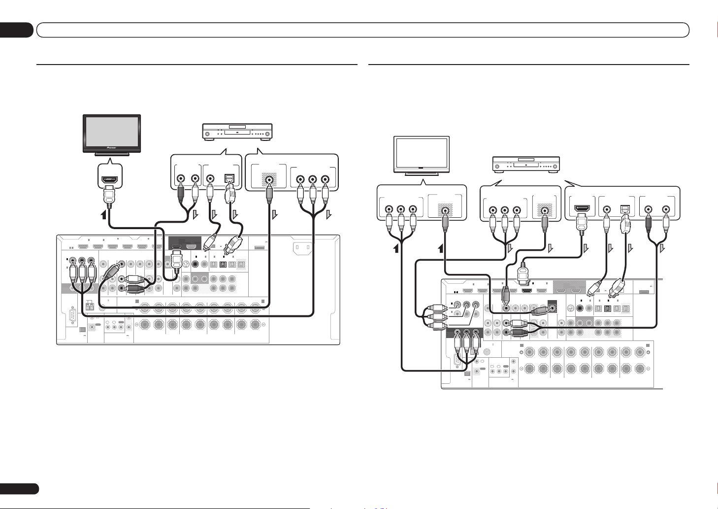
03 Connecting your equipment
Connecting your DVD player with no HDMI output
This diagram shows connections of a TV (with HDMI input) and DVD player (or other playback component with no HDMI output) to the receiver.
HDMI/DVI-compatible monitor
AUDIO OUT
R
(DVR/BDR)
ANALOG
6
OUT 1
(CONTROL)
SIRIUS
IN
MONITOR
OUT
VIDEO
CD
IN
FRONT
AUDIO
SURROUND
ASSIGNABLE
MONITOR
IN
(
DVD
IN
(
DVR/
BDR
OUT
HDMI
ASSIGNABLE
1
)
2
)
RS-232C
1 6
COMPONENT VIDEO
Y PBP
AM LOOP
(
OUTPUT 5 V
150 mA MAX
EXTENSION
IN1IN
ANTENNA
)
R
CONTROL
ZONE 2
FM UNBAL 75
IN
OUT
HDMI IN
2
IN
IN
(VIDEO)
ZONE 3
OUT
IR
1IN2
(OUTPUT 12 V
TOTAL 150 mA MAX)
4
IN5IN
(DVD)
BD IN
TV/SAT VIDEO
DVD
IN IN IN IN
SPEAKERS
R L R L
A
1
OUT
2
12 V TRIGGER
DVR/BDR
OUTOUT
FRONT CENTER
! If you want to listen to the sound of the TV over the receiver, connect the receiver and TV with audio
cables (page 17).
— When the TV and receiver are connected by HDMI connections, if the TV supports the HDMI ARC
(Audio Return Channel) function, the sound of the TV is input to the receiver via the HDMI OUT
terminal, so there is no need to connect an audio cable. In this case, set TV Audio at HDMI Setup
to via HDMI (see HDMI Setup on page 47 ).
! If you use an optical digital audio cable, you’ll need to tell the receiver which digital input you
connected the player to (see The Input Setup menu on page 28 ).
En
18
DVD player, etc.
Select one Select one
DIGITAL OUT
L
COAXIAL OPTICAL
DC OUTPUT
for WIRELESS LAN
OUT 2
(
OUTPUT
5 V
)
0.6 A MAX
COAXIAL
OPTICAL
ASSIGNABLE
ASSIGNABLE
2
IN1IN2IN3OUT
IN1IN
(CD)(
)
(
)
DVR/BDR)(TV/SAT
SURROUND SURR BACK
SURROUND BACK
R
(
VIDEO
FH / FW
(
)
Single
(
Single
L
DVD
SUBWOOFER
1 2
CENTER
ADAPTER PORT
LAN
(
)
10/100
)
PRE OUT
L
R
)
FRONT HEIGHT / FRONT WIDE /
R L
(
OUTPUT 5 V
0.1 A MAX
VIDEO OUT
VIDEO
)
B
AC IN
COMPONENT VIDEO OUT
PR
P
B
Connecting your TV with no HDMI input
This diagram shows connections of a TV (with no HDMI input) and DVD player (or other playback
component) to the receiver.
! With these connections, the picture is not output to the TV even if the DVD player is connected with
an HDMI cable. Connect the receiver and TV using the same type of video cable as used to connect
the receiver and player.
DVD player, etc.
VIDEO IN
VIDEO
ASSIGNABLE
MONITOR
IN
(
IN
(
DVR/
BDR
OUT
ASSIGNABLE
DVD
HDMI
1
2
)
RS-232C
)
TV
1 6
(
150 mA MAX
COMPONENT VIDEO
Y PBP
ANTENNA
AM LOOP
OUTPUT 5 V
)
EXTENSION
IN1IN
R
CONTROL
FM UNBAL 75
IN
OUT
ZONE 2
Select one Select one
COMPONENT VIDEO OUT
PR
4
IN
2
(VIDEO)
ZONE 3
OUT
IR
1IN2
IN
(OUTPUT 12 V
TOTAL 150 mA MAX)
12 V TRIGGER
P
B
Y
IN5IN
(DVD)
BD IN
TV/SAT VIDEO
DVD
IN IN IN IN
SPEAKERS
OUT
DVR/BDR
OUTOUT
FRONT CENTER
R L R L
A
1
2
VIDEO OUT
VIDEO
(DVR/BDR)
HDMI OUT
6
OUT 1
OUT 2
(CONTROL)
SIRIUS
COAXIAL
ASSIGNABLE
IN1IN
IN
MONITOR
OUT
AUDIO
VIDEO
)
DVD
CD
IN
SUBWOOFER
FRONT
1 2
CENTER
SURROUND
DC OUTPUT
for WIRELESS LAN
(
5 V
0.6 A MAX
OPTICAL
ASSIGNABLE
2
IN1IN2IN3OUT
(CD)(
)
SURROUND SURR BACK
SURROUND BACK
R
DIGITAL OUT
COAXIAL OPTICAL
OUTPUT
)
(
(
)
DVR/BDR)(TV/SAT
VIDEO
FH / FW
PRE OUT
(
)
Single
L
R
(
)
FRONT HEIGHT / FRONT WIDE /
Single
L
R L
LAN
(
10/100
ADAPTER PORT
)
(
OUTPUT 5 V
0.1 A MAX
AUDIO OUT
R
)
B
ANALOG
L
Y
Select one
COMPONENT VIDEO IN
P
R
P
B
Y
! Connect using an HDMI cable to listen to HD audio on the receiver. Do not use an HDMI cable to
input video signals.
Depending on the video component, it may not be possible to output signals connected by HDMI
and other methods simultaneously, and it may be necessary to make output settings. Please refer
to the operating instructions supplied with your component for more information.
! If you want to listen to the sound of the TV over the receiver, connect the receiver and TV with audio
cables (page 17).
! If you use an optical digital audio cable, you’ll need to tell the receiver which digital input you
connected the player to (see The Input Setup menu on page 28 ).
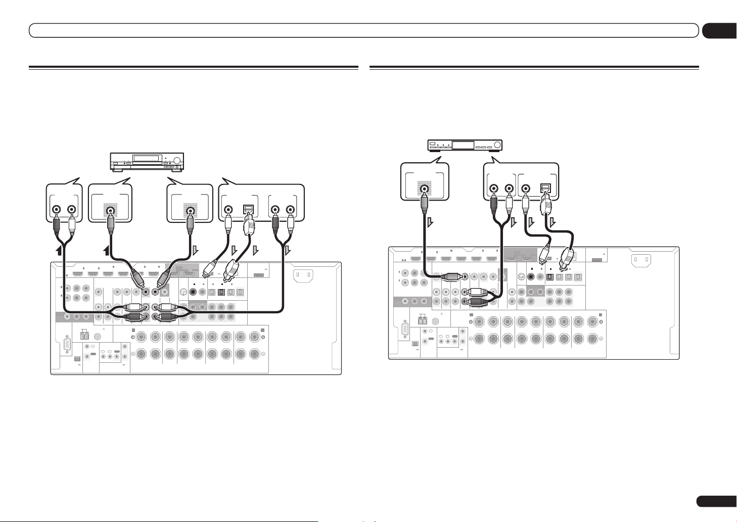
Connecting your equipment
03
Connecting an HDD/DVD recorder, BD recorder and other video
sources
This receiver has two sets of audio/video inputs and outputs suitable for connecting analog or digital video devices, including HDD/DVD recorders and BD recorders.
When you set up the receiver you’ll need to tell the receiver which input you connected the recorder
to (see also The Input Setup menu on page 28 ).
HDD/DVD recorder, BD recorder, etc.
AUDIO IN
R
ANALOG
ASSIGNABLE
MONITOR
IN
(
IN
(
DVR/
BDR
OUT
ASSIGNABLE
1
DVD
2
HDMI
)
)
RS-232C
L
1 6
COMPONENT VIDEO
Y PBP
AM LOOP
(
OUTPUT 5 V
150 mA MAX
EXTENSION
IN1IN
ANTENNA
)
R
CONTROL
ZONE 2
FM UNBAL 75
IN
OUT
2
ZONE 3
1IN2
IN
VIDEO IN
VIDEO
IN
(VIDEO)
OUT
IR
(OUTPUT 12 V
TOTAL 150 mA MAX)
12 V TRIGGER
4
IN5IN
BD IN
(DVD)
TV/SAT VIDEO
DVD
IN IN IN IN
SPEAKERS
R L R L
A
1
OUT
2
DVR/BDR
OUTOUT
FRONT CENTER
(DVR/BDR)
VIDEO OUT
VIDEO
6
OUT 1
DC OUTPUT
for WIRELESS LAN
OUT 2
(CONTROL)
SIRIUS
COAXIAL
OPTICAL
ASSIGNABLE
ASSIGNABLE
2
IN1IN
IN
MONITOR
OUT
AUDIO
VIDEO
(CD)(
)
DVD
CD
IN
SUBWOOFER
FRONT
SURROUND SURR BACK
1 2
CENTER
SURROUND
R
! In order to record, you must connect the analog audio cables (the digital connection is for playback
only) (page 54).
! If your HDD/DVD recorder, BD recorder, etc., is equipped with an HDMI output terminal, we
recommend connecting it to the receiver’s HDMI DVR/BDR IN terminal. When doing so, also
connect the receiver and TV by HDMI (see Connecting using HDMI on page 17 ).
DIGITAL OUT
COAXIAL OPTICAL
(
OUTPUT
5 V
)
0.6 A MAX
IN1IN2IN3OUT
(
)
(
)
DVR/BDR)(TV/SAT
VIDEO
FH / FW
(
)
Single
(
SURROUND BACK
Single
L
Select one
ADAPTER PORT
(
OUTPUT 5 V
LAN
0.1 A MAX
(
)
10/100
PRE OUT
L
R
)
FRONT HEIGHT / FRONT WIDE /
R L
B
)
AUDIO OUT
R L
ANALOG
AC IN
Connecting a satellite/cable receiver or other set-top box
Satellite and cable receivers, and terrestrial digital TV tuners are all examples of so-called ‘set-top
boxes’.
When you set up the receiver you’ll need to tell the receiver which input you connected the set-top
box to (see The Input Setup menu on page 28 ).
STB
VIDEO OUT
VIDEO
4
IN
2
MONITOR
ASSIGNABLE
(
OUT
ASSIGNABLE
IN
(
DVD
IN
DVR/
BDR
HDMI
1
)
2
)
RS-232C
1 6
COMPONENT VIDEO
Y PBP
ANTENNA
AM LOOP
(
OUTPUT 5 V
150 mA MAX
EXTENSION
IN1IN
)
R
CONTROL
ZONE 2
FM UNBAL 75
IN
OUT
(VIDEO)
DVD
ZONE 3
OUT
IN IN IN IN
SPEAKERS
IR
OUT
1IN2
IN
(OUTPUT 12 V
TOTAL 150 mA MAX)
12 V TRIGGER
BD IN
TV/SAT VIDEO
1
2
! If your set-top box is equipped with an HDMI output terminal, we recommend connecting it to the
receiver’s HDMI IN 1 or IN 2 terminal. When doing so, also connect the receiver and TV by HDMI
(see Connecting using HDMI on page 17 ).
Select one
AUDIO OUT
R
L
ANALOG
COAXIAL OPTICAL
6
IN5IN
(DVD)
OUTOUT
FRONT CENTER
R L R L
A
DVR/BDR
(DVR/BDR)
MONITOR
AUDIO
OUT 1
(CONTROL)
SIRIUS
IN
OUT
VIDEO
CD
IN
FRONT
DIGITAL OUT
COAXIAL
ASSIGNABLE
IN1IN
DVD
1 2
CENTER
SURROUND
OUT 2
)
SUBWOOFER
DC OUTPUT
for WIRELESS LAN
OPTICAL
ASSIGNABLE
2
IN1IN2IN3OUT
(CD)(
SURROUND SURR BACK
SURROUND BACK
R
ADAPTER PORT
(
OUTPUT 5 V
LAN
(
OUTPUT
(
)
10/100
5 V
)
0.6 A MAX
(
)
(
)
DVR/BDR)(TV/SAT
VIDEO
FH / FW
PRE OUT
(
)
Single
L
R
(
)
FRONT HEIGHT / FRONT WIDE /
Single
L
R L
0.1 A MAX
AC IN
)
B
En
19
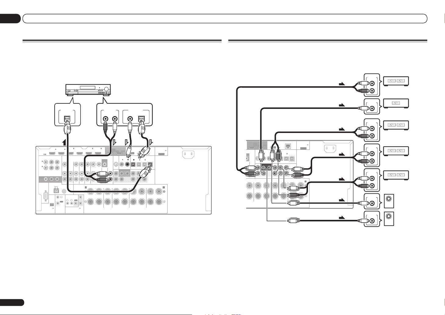
03 Connecting your equipment
Connecting other audio components
This receiver has both digital and analog inputs, allowing you to connect audio components for
playback.
When you set up the receiver you’ll need to tell the receiver which input you connected the component to (see also The Input Setup menu on page 28 ).
MD, DAT, etc.
Select one
AUDIO OUT
R L
ANALOG
6
IN5IN
(DVD)
(DVR/BDR)
MONITOR
OUT
VIDEO
CD
DVR/BDR
IN
OUTOUT
AUDIO
FRONT CENTER
R L R L
ASSIGNABLE
MONITOR
IN
(
IN
(
DVR/
BDR
OUT
HDMI
ASSIGNABLE
1 6
Y PBP
1
)
DVD
2
)
RS-232C
(
OUTPUT 5 V
150 mA MAX
COMPONENT VIDEO
AM LOOP
EXTENSION
IN1IN
R
ANTENNA
CONTROL
)
DIGITAL IN
ZONE 2
FM UNBAL 75
IN
OUT
OPTICAL
2
ZONE 3
OUT
1IN2
IN
4
IN
SPEAKERS
IR
(OUTPUT 12 V
TOTAL 150 mA MAX)
12 V TRIGGER
BD IN(VIDEO)
TV/SAT VIDEO
DVD
IN IN IN IN
A
1
OUT
2
! If your turntable has line-level outputs (i.e., it has a built-in phono pre-amp), connect it to the CD
inputs instead.
! You can’t hear HDMI audio through this receiver’s digital out jack.
En
20
OUT 1
(CONTROL)
SIRIUS
FRONT
IN
SURROUND
COAXIAL OPTICAL
OUT 2
COAXIAL
ASSIGNABLE
IN1IN
(CD)(
)
DVD
SUBWOOFER
1 2
CENTER
DIGITAL OUT
DC OUTPUT
for WIRELESS LAN
(
OUTPUT
5 V
0.6 A MAX
OPTICAL
ASSIGNABLE
2
IN1IN2IN3OUT
(
)
DVR/BDR)(TV/SAT
SURROUND SURR BACK
SURROUND BACK
R
)
(
VIDEO
FH / FW
(
)
Single
L
LAN
(
10/100
)
PRE OUT
L
R
(
)
FRONT HEIGHT / FRONT WIDE /
Single
R L
ADAPTER PORT
)
(
OUTPUT 5 V
0.1 A MAX
AC IN
)
B
Connecting additional amplifiers
This receiver has more than enough power for any home use, but it’s possible to add additional
amplifiers to every channel of your system using the pre-outs. Make the connections shown below
to add amplifiers to power your speakers.
ANALOG
INPUT
L
Front channel
R
amplifier
ANALOG
INPUT
Center channel
amplifier (mono)
ANALOG
INPUT
L
Surround
R
channel amplifier
ANALOG
INPUT
L
Front height or Front wide
R
channel amplifier
ANALOG
INPUT
L
Surround back
R
channel amplifier
ANALOG
INPUT
ANALOG
INPUT
Powered
subwoofer 2
Powered
subwoofer 1
OUT 1
DC OUTPUT
for WIRELESS LAN
OUT 2
(CONTROL)
SIRIUS
IN
ITOR
UT
VIDEO
CD
IN
FRONT
DIO
CENTER
R L
COAXIAL
ASSIGNABLE
IN1IN
DVD
1 2
CENTER
SURROUND
)
SUBWOOFER
OPTICAL
ASSIGNABLE
2
IN1IN2IN3OUT
(CD)(
SURROUND SURR BACK
SURROUND BACK
R
(
OUTPUT
5 V
0.6 A MAX
(
)
DVR/BDR)(TV/SAT
)
(
VIDEO
FH / FW
(
)
Single
(
Single
L
ADAPTER PORT
LAN
(
)
10/100
)
PRE OUT
L
R
)
FRONT HEIGHT / FRONT WIDE /
R L
(
OUTPUT 5 V
0.1 A MAX
AC IN
)
B
! If you’re not using a subwoofer, change the front speaker setting (see Speaker Setting on page 66 ) to
LARGE.
! You can use the additional amplifier on the surround back channel pre-outs for a single speaker as
well. In this case plug the amplifier into the left (SURROUND BACK L (Single)) terminal only.
! The sound from the surround back terminals will depend on how you have configured the Speaker
system setting on page 69 .
! If you have two subwoofers, the second subwoofer can be connected to the SUBWOOFER 2
terminal. Connecting two subwoofers increases the bass sound to achieve more powerful sound
reproduction. In this case, the same sound is output from the two subwoofers.
! To hear sound only from the pre-outs, switch the speaker system to OFF, or simply disconnect any
speakers that are connected directly to the receiver.

Connecting your equipment
RS-232C
ZONE 2
IN IN
OUT
ZONE 3
OUT
TV/SAT VDVD
COMPONENT VIDEO
Y PBP
R
ASSIGNABLE
MONITOR
OUT
(
DVD
)
IN
1
(
DVR/
BDR
)
IN
2
BD IN
EXTENSION
SPEAKERS
A
FM UNBAL 75
AM LOOP
ANTENNA
(
OUTPUT 5 V
150 mA MAX
)
CONTROL
IR
OUT
IN
OUT
IN
1IN2
2
1
12 V TRIGGER
(OUTPUT 12 V
TOTAL 150 mA MAX)
03
Connecting AM/FM antennas
Connect the AM loop antenna and the FM wire
antenna as shown below. To improve reception
and sound quality, connect external antennas
(see Connecting external antennas on page 21 ).
1
5
a b c
1 Pull off the protective shields of both
AM antenna wires.
2 Push open the tabs, then insert one
wire fully into each terminal, then release
the tabs to secure the AM antenna wires.
3 Fix the AM loop antenna to the
attached stand.
To fix the stand to the antenna, bend in the
direction indicated by the arrow (fig. a) then clip
the loop onto the stand (fig. b).
! If you plan to mount the AM antenna to a
wall or other surface, secure the stand with
screws (fig. c) before clipping the loop to the
stand. Make sure the reception is clear.
4 Place the AM antenna on a flat
surface and in a direction giving the best
reception.
ANTENNA
FM UNBAL 75 AM LOOP
5 Connect the FM wire antenna into the
FM antenna socket.
For best results, extend the FM antenna fully
and fix to a wall or door frame. Don’t drape
loosely or leave coiled up.
MULTI-ZONE setup
This receiver can power up to three (VSX-53)/
two (VSX-52) independent systems in separate
rooms after you have made the proper MULTIZONE connections.
Connecting external antennas
2
To improve FM reception, connect an external
FM antenna to FM UNBAL 75 W.
Different sources can be playing in three (VSX-
53)/two (VSX-52) zones at the same time or,
depending on your needs, the same source can
also be used. The main and sub zone have independent power (the main zone power can be off
3
4
75 Ω coaxial cable
ANTENNA
FM UNBAL 75 AM LOOP
while one (or both) of the sub zones is on) and
the sub zones can be controlled by the remote
or front panel controls.
Important
The explanations for ZONE 3 below only apply to
the VSX-53.
Sub
Input functions available
Zone
DVD, TV/SAT, DVR/BDR, VIDEO, CD,
ZONE 3
TUNER, ADAPTER PORT
(Outputs analog audio)
It is not possible to down-convert the audio
and video input signals from the HDMI input
terminals, digital input terminals (OPTICAL and
COAXIAL) and the COMPONENT VIDEO input
terminals and output them to ZONE 2.
Basic MULTI-ZONE setup (ZONE 2)
1 Connect a separate amplifier to the
AUDIO ZONE 2 OUT jacks on this receiver.
You should have a pair of speakers attached to
the sub zone amplifier as shown in the following illustration.
2 Connect a TV monitor to the VIDEO
To improve AM reception, connect a 5 m to 6 m
(16 ft. to 20 ft.) length of vinyl-coated wire to the
AM LOOP terminals without disconnecting the
supplied AM loop antenna.
For the best possible reception, suspend horizontally outdoors.
Outdoor antenna
Indoor antenna
ANTENNA
FM UNBAL 75 AM LOOP
(vinyl-coated wire)
5 m to 6 m
(16 ft. to 20 ft.)
Making MULTI-ZONE connections
It is possible to make these connections if
you have a separate TV and speakers for your
primary (ZONE 2) sub zone, and a separate TV
and a separate amplifier (and speakers) for your
secondary (ZONE 3) sub zone. You will also
need a separate amplifier if you are not using
the MULTI-ZONE setup using speaker terminals
(ZONE 2) on page 21 for your primary sub zone.
There are two primary sub zone setups possible
with this system. Choose whichever works best
for you.
MULTI-ZONE listening options
The following table shows the signals that can
be output to ZONE 2 and ZONE 3:
Sub
Input functions available
Zone
DVD, TV/SAT, DVR/BDR, VIDEO,
ZONE 2
HOME MEDIA GALLERY, iPod/USB,
CD, TUNER, ADAPTER PORT, SIRIUS
(Outputs analog audio, composite
video.)
ZONE 2 OUT jack on this receiver.
Sub zone (ZONE 2)
VIDEO IN
AUDIO IN
R L
Main zone
HDMI
ASSIGNABLE
1 6
IN1IN
4
IN
2
(VIDEO)
MULTI-ZONE setup using speaker
terminals (ZONE 2)
You must select ZONE 2 in Speaker system setting on page 69 to use this setup.
1 Connect a pair of speakers to the
surround back speaker terminals.
En
21
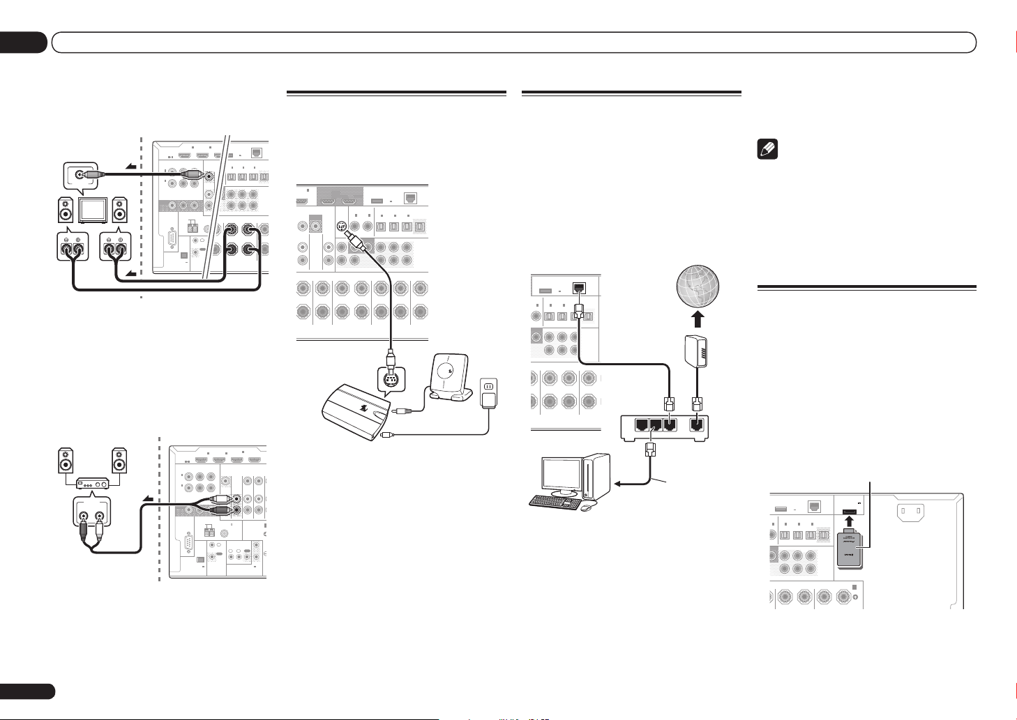
03 Connecting your equipment
F
L
R
PRE O
2
TER
SURROUND SURR BACK
FH / FW
(CD)
)
1IN2
(
DVR/BDR)(TV/SAT
)
OPTICAL
ASSIGNABLE
IN1IN2IN3OUT
(
VIDEO
)
DC OUTPUT
for WIRELESS LAN
(
10/10
LAN
(
OUTPUT
5 V
0.6 A MAX
)
SURROUND BACK
LRR L
(
Single
)
(
Single
)
FRONT HE
RS-232C
ZONE 2
OUT
ZONE 3
OUT
COMPONENT VIDEO
Y PBP
R
ASSIGNABLE
MONITOR
OUT
(
DVD
)
IN
1
(
DVR/
BDR
)
IN
2
HDMI
IN1IN
2
ASSIGNABLE
1 6
EXTENSION
FM UNBAL 75
AM LOOP
ANTENNA
(
OUTPUT 5 V
150 mA MAX
)
CONTROL
IR
OUT
IN
IN1IN
(OU
TO
RS-232C
ZONE 2
IN IN
OUT
ZONE 3
OUT
TV/SAT VDVD
COMPONENT VIDEO
Y PBP
R
ASSIGNABLE
MONITOR
OUT
(
DVD
)
IN
1
(
DVR/
BDR
)
IN
2
BD IN
EXTENSION
SPEAKERS
A
FM UNBAL 75
AM LOOP
ANTENNA
(
OUTPUT 5 V
150 mA MAX
)
CONTROL
IR
OUT
IN
OUT
IN
1IN2
2
1
12 V TRIGGER
(OUTPUT 12 V
TOTAL 150 mA MAX)
T
H
2 Connect a TV monitor to the VIDEO
ZONE 2 OUT jack on this receiver.
Sub zone (ZONE 2)
VIDEO IN
Main zone
RL
Secondary MULTI-ZONE setup (ZONE
3)
% Connect a separate amplifier to the
AUDIO ZONE 3 OUT jacks on this receiver.
You should have a pair of speakers attached to
the sub zone amplifier as shown in the following illustration.
Main zone
HDMI
ASSIGNABLE
1 6
22
Sub zone (ZONE 3)
En
R L
AUDIO IN
IN1IN
Connecting a SiriusConnect
Tuner
To receive SIRIUS Satellite Radio broadcasts,
you will need to activate your SiriusConnectTM
tuner.
6
IN
OUT 1
(CONTROL)
SIRIUS
IN
FRONT
SURROUND
SIRIUS
OUT 2
COAXIAL
ASSIGNABLE
IN1IN
)
DVD
SUBWOOFER
1 2
CENTER
TM
DC OUTPUT
for WIRELESS LAN
OPTICAL
ASSIGNABLE
2
IN1IN2IN3OUT
(CD)(
SURROUND SURR BACK
SURROUND BACK
H
LAN
(
OUTPUT
(
)
10/100
5 V
)
0.6 A MAX
(
)
(
)
DVR/BDR)(TV/SAT
VIDEO
FH / FW
PRE OU
(
)
Single
L
R
(
)
FRONT HEIG
Single
L
Antenna
H
SIRIUS
AC adapter
(DVR/BDR)
MONITOR
OUT
VIDEO
CD
BDR
IN
IN
AUDIO
T CENTER
L R LRR
SiriusConnect
HOME tuner
4
IN
2
(VIDEO)
You will also need to connect the antenna and
AC adapter to the SiriusConnectTM tuner.
! For instructions on playing the SIRIUS Radio,
see Listening to Satellite Radio on page 33 .
Connecting to the network
through LAN interface
By connecting this receiver to the network via
the LAN terminal, you can listen to Internet
radio stations. To listen to Internet radio stations, you must sign a contract with an ISP
(Internet Service Provider) beforehand.
When connected in this way, you can play audio
files stored on the components on the network,
including your computer, using HOME MEDIA
GALLERY inputs.
DC OUTPUT
for WIRELESS LAN
OPTICAL
LE
ASSIGNABLE
2
IN1IN2IN3OUT
IN
(CD)
OFER2SURROUND SURR BACK
LRR
Connect the LAN terminal on this receiver to
the LAN terminal on your router (with or without the built-in DHCP server function) with a
straight LAN cable (CAT 5 or higher).
Turn on the DHCP server function of your
(
OUTPUT
5 V
0.6 A MAX
(
)
DVR/BDR)(TV/SAT
SURROUND BACK
PC
LAN
(
)
10/100
)
(
)
VIDEO
FH / FW
PRE OUT
(
)
Single
L
R
(
)
FRONT HEIGHT /
Single
L
LAN
Internet
Modem
3 2 1
WAN
Router
LAN cable
(sold separately)
to LAN port
! LAN terminal : Ethernet jack
(10BASE-T/100BASE-TX)
Note
! Refer to the operation manual of the
equipment you have as the connected
equipment and connection method may differ
depending on your Internet environment.
! When using a broadband Internet connection,
a contract with an Internet service provider
is required. For more details, contact your
nearest Internet service provider.
Connecting optional Bluetooth
ADAPTER
When the Bluetooth® ADAPTER (AS-BT100 or
AS-BT200) is connected to this receiver, a product equipped with Bluetooth wireless technology (portable cell phone, digital music player,
etc.) can be used to listen to music wirelessly.
! The Bluetooth wireless technology enabled
device must support A2DP profiles.
! Pioneer does not guarantee proper connection
and operation of this unit with all Bluetooth
wireless technology enabled devices.
Bluetooth® ADAPTER
)
(
VIDEO
FH / FW
(
)
Single
L
LAN
(
)
10/100
)
PRE OUT
L
R
(
)
FRONT HEIGHT / FRONT WIDE /
Single
R L
ADAPTER PORT
(
OUTPUT 5 V
0.1 A MAX
AC IN
)
B
DC OUTPUT
for WIRELESS LAN
(
OUTPUT
5 V
0.6 A MAX
OPTICAL
ASSIGNABLE
2
IN1IN2IN3OUT
N
)
(
)
CD
DVR/BDR)(TV/SAT
ER2SURROUND SURR BACK
SURROUND BACK
R
router. In case your router does not have the
built-in DHCP server function, it is necessary
to set up the network manually. For details, see
Network Setup menu on page 71 .
LAN terminal specifications
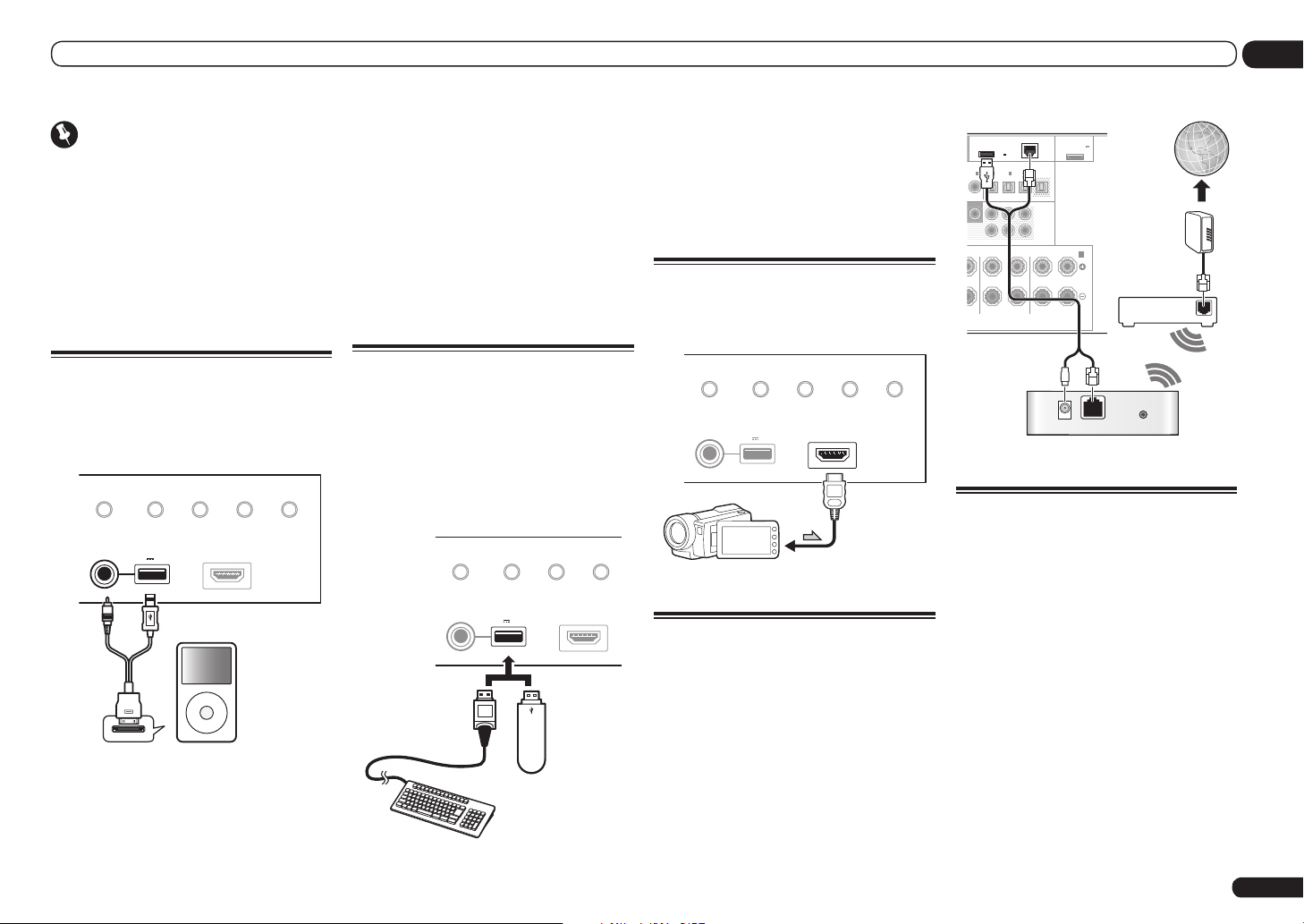
Connecting your equipment
03
Important
! Do not move the receiver with the Bluetooth
ADAPTER connected. Doing so could cause
damage or faulty contact.
% Switch the receiver into standby
and connect Bluetooth ADAPTER to the
ADAPTER PORT.
! For instructions on playing the Bluetooth
wireless technology device, see Pairing the
Bluetooth ADAPTER and Bluetooth wireless
technology device on page 35 .
Connecting an iPod
This receiver has a dedicated iPod terminal
that will allow you to control playback of audio
content from your iPod using the controls of
this receiver.
iPod iPhone iPad
DIRECT CONTROL
iPod cable
(supplied)
AUTO SURR/ALC/
STREAM DIRE CT HOME THX
USB
5V 2.1 A
iPod iPhone iPad
ADVANCED
SURROUND
iPod
HDMI 3 INPUT
MENU
STANDARD
SURROUND
% Switch the receiver into standby then
use the supplied iPod cable to connect
your iPod to the iPod iPhone iPad USB
terminal on the front panel of this
receiver.
! It is also possible to connect using the cable
included with the iPod, but in this case it is not
possible to view pictures via the receiver.
! For the cable connection, also refer to the
operating instructions for your iPod.
! For instructions on playing the iPod, see
Playing an iPod on page 30 .
Connecting a USB device
It is possible to play audio and photo files by
connecting USB devices to this receiver. It
is also possible to connect a USB keyboard
(US-international layout) to the receiver to enter
text in the following GUI screens.
! Change the input name in the Input Setup
menu (page 28).
! Add names to radio station presets (page 33).
iPod iPhone iPad
DIRECT CONTROL
AUTO SURR/ALC/
STREAM DIRE CT
USB
5V 2.1 A
iPod iPhone iPad
USB keyboard
USB mass
storage device
ADVANCED
SURROUND
STANDARD
SURROUND
HDMI 3 INPUT
% Switch the receiver into standby
then connect your USB device to the
USB terminal on the front panel of this
receiver.
! This receiver does not support a USB hub.
! For instructions on playing the USB device,
see Playing a USB device on page 31 .
Connecting an HDMI-equipped
component to the front panel
input
AUTO SURR/ALC/
iPod iPhone iPad
DIRECT CONTROL
STREAM DIRE CT HOME THX
USB
5V 2.1 A
iPod iPhone iPad
Video camera (etc.)
ADVANCED
SURROUND
STANDARD
SURROUND
HDMI 3 INPUT
Connecting to a wireless LAN
Wireless connection to the network is possible
through a wireless LAN connection. Use the
separately sold AS-WL300 for connection.
! For instructions on setting the wireless LAN
converter, see Network Setup menu on page
71 .
)
(
VIDEO
FH / FW
(
)
Single
L
LAN
(
10/100
)
PRE OUT
L
R
(
)
FRONT HEIGHT / FRONT WIDE /
Single
R L
ADAPTER PORT
)
(
OUTPUT 5 V
0.1 A MAX
)
Internet
Modem
B
DC OUTPUT
for WIRELESS LAN
(
OUTPUT
5 V
0.6 A MAX
L
OPTICAL
BLE
ASSIGNABLE
2
IN1IN2IN3OUT
IN
(CD)
)
OFER2SURROUND SURR BACK
SURROUND BACK
L
R
(
DVR/BDR)(TV/SAT
Router
WAN
DC 5V WPS
Ethernet
Wireless LAN converter (AS-WL300)
Connecting an IR receiver
If you keep your stereo components in a closed
cabinet or shelving unit, or you wish to use the
sub zone remote control in another zone, you
can use an optional IR receiver (such as a Niles
or Xantech unit) to control your system instead
of the remote sensor on the front panel of this
receiver.
! Remote operation may not be possible if direct
light from a strong fluorescent lamp is shining
on the IR receiver remote sensor window.
! Note that other manufacturers may not use
the IR terminology. Refer to the manual that
came with your component to check for IR
compatibility.
! If using two remote controls (at the same
time), the IR receiver’s remote sensor takes
priority over the remote sensor on the front
panel.
En
23
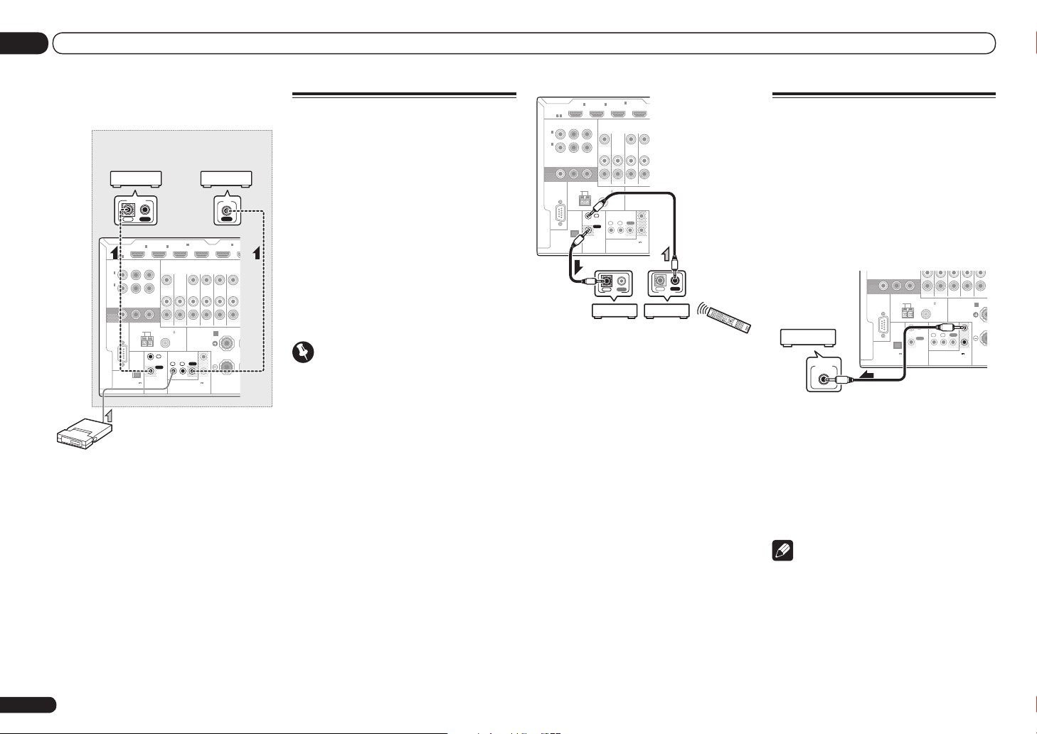
03 Connecting your equipment
T
1 Connect the IR receiver sensor to the IR
IN jack on the rear of this receiver.
Closet or shelving unit
Pioneer
component
CONTROL
IN OUT
HDMI
ASSIGNABLE
1 6
ASSIGNABLE
COMPONENT VIDEO
Y PBP
1
IN
(
)
DVD
2
IN
(
DVR/
)
BDR
MONITOR
OUT
RS-232C
AM LOOP
(
OUTPUT 5 V
150 mA MAX
EXTENSION
IN1IN
R
ANTENNA
CONTROL
)
FM UNBAL 75
OUT
Non-Pioneer
component
IR
IN
4
IN
2
(VIDEO)
ZONE 2
ZONE 3
OUT
IR
IN
1IN2
IN
(OUTPUT 12 V
TOTAL 150 mA MAX)
12 V TRIGGER
BD IN
TV/SAT VIDEODVD
IN IN IN
SPEAKERS
OUT
5
IN
(DVD)
DVR/
OUTOUT
FRON
R
A
1
2
IR receiver
2 Connect the IR IN jack of another
component to the IR OUT jack on the rear
of this receiver to link it to the IR receiver.
Please see the manual supplied with your IR
receiver for the type of cable necessary for the
connection.
! If you want to link a Pioneer component to
the IR receiver, see Operating other Pioneer
components with this unit’s sensor on page
24 to connect to the CONTROL jacks instead
of the IR OUT jack.
Operating other Pioneer
components with this unit’s
sensor
Many Pioneer components have SR CONTROL
jacks which can be used to link components
together so that you can use just the remote
sensor of one component. When you use a
remote control, the control signal is passed
along the chain to the appropriate component.
! If you want to control all your components
using this receiver’s remote control, see page
56.
! If you have connected a remote control to the
CONTROL IN jack (using a mini-plug cable),
you won’t be able to control this unit using the
remote sensor.
Important
! Note that if you use this feature, make sure
that you also have at least one set of analog
audio, video or HDMI jacks connected to
another component for grounding purposes.
1 Decide which component you want to
use the remote sensor of.
When you want to control any component in the
chain, this is the remote sensor at which you’ll
point the corresponding remote control.
2 Connect the CONTROL OUT jack of that
component to the CONTROL IN jack of
another Pioneer component.
Use a cable with a mono mini-plug on each end
for the connection.
4
IN
2
IN1IN
(VIDEO)
OUT
IN OUT
CONTROL
ZONE 3
OUT
IR
1IN2
IN
(OUTPUT 12 V
TOTAL 150 mA MAX)
12 V TRIGGER
IN IN
SPEAKERS
OUT
BD IN
TV/SATDVD
1
2
IN OUT
CONTROL
ASSIGNABLE
IN
(
DVD
IN
(
DVR/
BDR
MONITOR
OUT
HDMI
ASSIGNABLE
1 6
Y PBP
1
)
2
)
RS-232C
(
OUTPUT 5 V
150 mA MAX
COMPONENT VIDEO
ANTENNA
AM LOOP
)
EXTENSION
R
CONTROL
ZONE 2
FM UNBAL 75
IN
OUT
3 Continue the chain in the same way for
as many components as you have.
Switching components on and
off using the 12 volt trigger
You can connect components in your system
(such as a screen or projector) to this receiver
so that they switch on or off using 12 volt
triggers when you select an input function.
However, you must specify which input functions switch on the trigger using the The Input
Setup menu on page 28 . Note that this will only
work with components that have a standby
mode.
MONITOR
OUT
ANTENNA
RS-232C
FM UNBAL 75
AM LOOP
(
OUTPUT 5 V
)
12 V TRIGGER
INPUT
150 mA MAX
EXTENSION
% Connect the 12 V TRIGGER jack of this
receiver to the 12 V trigger of another
component.
Use a cable with a mono mini-plug on each end
for the connection.
After you’ve specified the input functions that
will switch on the trigger, you’ll be able to
switch the component on or off just by pressing
the input function(s) you’ve set on page 28.
Note
! VSX-53 only:
It is also possible to have the component
switch not when the input function is
switched, but when HDMI OUT is switched.
For details, see HDMI Setup on page 47 .
CONTROL
SPEAKERS
R
A
IR
IN
OUT
1IN2
IN
(OUTPUT 12 V
TOTAL 150 mA MAX)
OUT
12 V TRIGGER
1
2
24
En

Connecting your equipment
03
Plugging in the receiver
Only plug in after you have connected all your
components to this receiver, including the
speakers.
CAUTION
! Handle the power cord by the plug part. Do
not pull out the plug by tugging the cord, and
never touch the power cord when your hands
are wet, as this could cause a short circuit or
electric shock. Do not place the unit, a piece of
furniture, or other object on the power cord or
pinch the cord in any other way. Never make
a knot in the cord or tie it with other cables.
The power cords should be routed so that they
are not likely to be stepped on. A damaged
power cord can cause a fire or give you an
electric shock. Check the power cord once in a
while. If you find it damaged, ask your nearest
Pioneer authorized independent service
company for a replacement.
! Do not use any power cord other than the one
supplied with this unit.
! Do not use the supplied power cord for any
purpose other than that described below.
! The receiver should be disconnected by
removing the mains plug from the wall
socket when not in regular use, e.g., when on
vacation.
! Make sure the blue u STANDBY/ON light has
gone out before unplugging.
! If you have connected speakers with a 6 W
impedance, change the impedance setting
before turning on the power.
1 Plug the supplied power cord into the
AC IN socket on the back of the receiver.
2 Plug the other end into a power outlet.
! After this receiver is connected to an AC
outlet, a 2 second to 10 second HDMI
initialization process begins. You cannot
carry out any operations during this process.
The HDMI indicator in the front panel display
blinks during this process, and you can turn
on this receiver once it has stopped blinking.
When you set the Control with HDMI to OFF,
you can skip this process. For details about
the Control with HDMI feature, see Control
with HDMI function on page 47 .
En
25
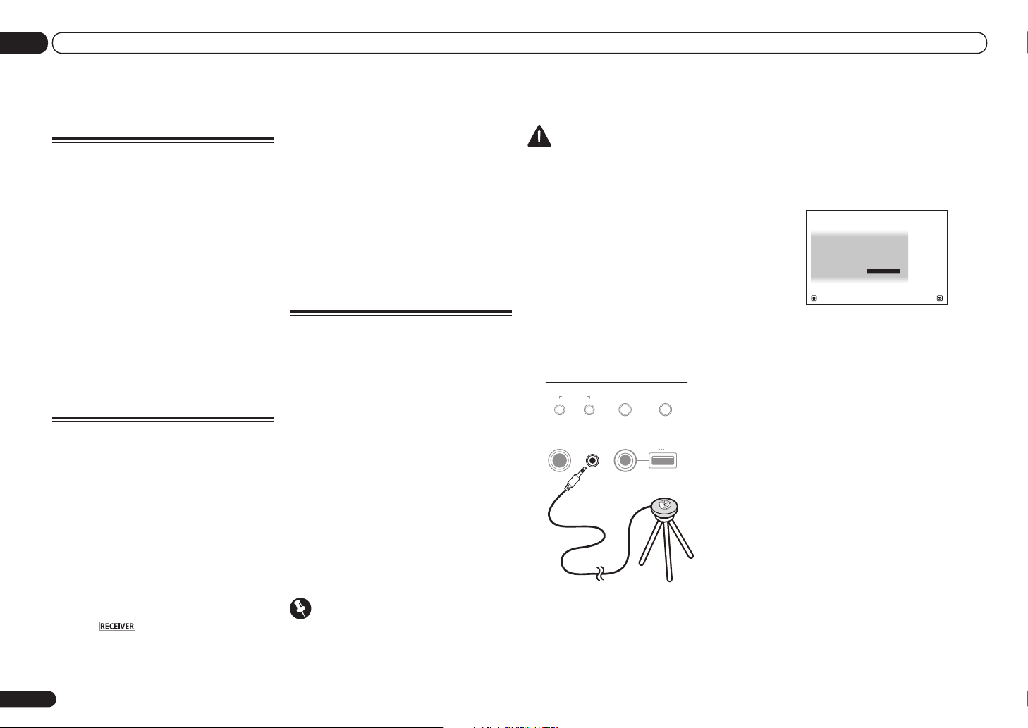
04 Basic Setup
Basic Setup
Switching the speaker
impedance
We recommend using speakers of 8 W with this
system, but it is possible to switch the impedance setting if you plan to use speakers with a 6
W impedance rating.
1 Switch the receiver into standby.
2 While holding down ENTER on the
front panel, press u STANDBY/ON.
The display shows RESET c NO d.
3 Use TUNE i/j to select SPEAKER c
8W d, and then use PRESET k/l to select
SPEAKER 8W or SPEAKER 6W.
! SPEAKER 8W – Use this setting if your
speakers are rated at 8 W or more.
! SPEAKER 6W – Use this setting if your
speakers are rated at 6 W.
Changing the OSD display
language (OSD Language)
The language used on the Graphical User
Interface screen can be changed.
! The explanations in these operating
instructions are for when English is selected
for the GUI screen.
1 Press u RECEIVER to switch on the
receiver and your TV.
Make sure that the TV’s video input is set to
this receiver (for example, if you connected this
receiver to the VIDEO jacks on your TV, make
sure that the VIDEO input is now selected).
2 Press on the remote control,
then press HOME MENU.
A Graphical User Interface (GUI) screen
appears on your TV. Use i/j/k/l and
ENTER to navigate through the screens and
En
26
select menu items. Press RETURN to exit the
current menu.
3 Select ‘System Setup’ from the Home
Menu.
4 Select ‘OSD Language’ from the
System Setup menu.
5 Select the desired language.
6 Select ‘OK’ to change the language.
The setting is completed and the System Setup
menu reappears automatically.
Automatically conducting
optimum sound tuning (Full
Auto MCACC)
The Full Auto MCACC Setup measures the
acoustic characteristics of your listening area,
taking into account ambient noise, speaker
connection and speaker size, and tests for both
channel delay and channel level. After you have
set up the microphone provided with your system, the receiver uses the information from a
series of test tones to optimize the speaker settings and equalization for your particular room.
VSX-53 only: By performing the Full Auto
MCACC Setup procedure, the frequency-phase
characteristics of the connected speakers are
also calibrated.
Once the Full Auto MCACC Setup procedure is
completed, the Full Band Phase Control function is automatically turned on (page 39).
Important
! Make sure the microphone and speakers are
not moved during the Full Auto MCACC Setup.
! Using the Full Auto MCACC Setup will
overwrite any existing settings for the MCACC
preset you select.
! Before using the Full Auto MCACC Setup, the
headphones should be disconnected.
CAUTION
! The test tones used in the Full Auto MCACC
Setup are output at high volume.
®
THX
! THX is a trademark of THX Ltd., which may
be registered in some jurisdictions. All rights
reserved.
1 Press u RECEIVER to switch on the
receiver and your TV.
Make sure that the TV’s video input is set to this
receiver.
2 Connect the microphone to the MCACC
SETUP MIC jack on the front panel.
Push down on the lower portion of the front
panel door to access the MCACC SETUP MIC
jack.
AUTO SURR/ALC/
MCACC
SETUP MIC
iPod iPhone iPad
DIRECT CONTROL
STREAM DIRE CT
5V 2.1 A
iPod iPhone iPad
USB
Microphone
Tripod
MULTI-ZONE
CONTROL ON/OFF
PHONES
Make sure there are no obstacles between the
speakers and the microphone.
If you have a tripod, use it to place the microphone so that it’s about ear level at your
normal listening position. If you do not have
a tripod, use some other object to install the
microphone.
Install the microphone on a stable floor.
Placing the microphone on any of the following
surfaces may make accurate measurement
impossible:
! Sofas or other soft surfaces.
! High places such as tabletops and sofa tops.
The Full Auto MCACC display appears once the
microphone is connected.
1a.Full Auto MCACC
A/V RECEIVER
Speaker System : Normal(SB/FH
EQ Type : SYMMETRY
MCACC : M1.MEMORY 1
THX Speaker : NO
START
Exit Retu rn
)
! If you leave the GUI screen for over five
minutes, the screen saver will appear.
3 Select the parameters you want to set.
! When data measurement is taken, the
reverb characteristics data (both before- and
after-calibration) that this receiver had been
storing will be overwritten.
! When measurement is taken of the reverb
characteristics data other than SYMMETRY,
the data are not measured after the
correction. If you will need to measure after
correcting data, take the measurement
using the EQ Professional menu in the
Manual MCACC setup (page 64).
If the speakers are connected using any setup
other than Normal(SB/FH), be sure to set
Speaker System before the Full Auto MCACC
Setup. See Speaker system setting on page 69 .
! Speaker System – Shows the current
settings. When this is selected and ENTER is
pressed, the speaker system selection screen
appears. Select the proper speaker system,
then press RETURN to return.
If you are planning on bi-amping your front
speakers, or setting up a separate speaker
system in another room, read through
Speaker system setting on page 69 and make
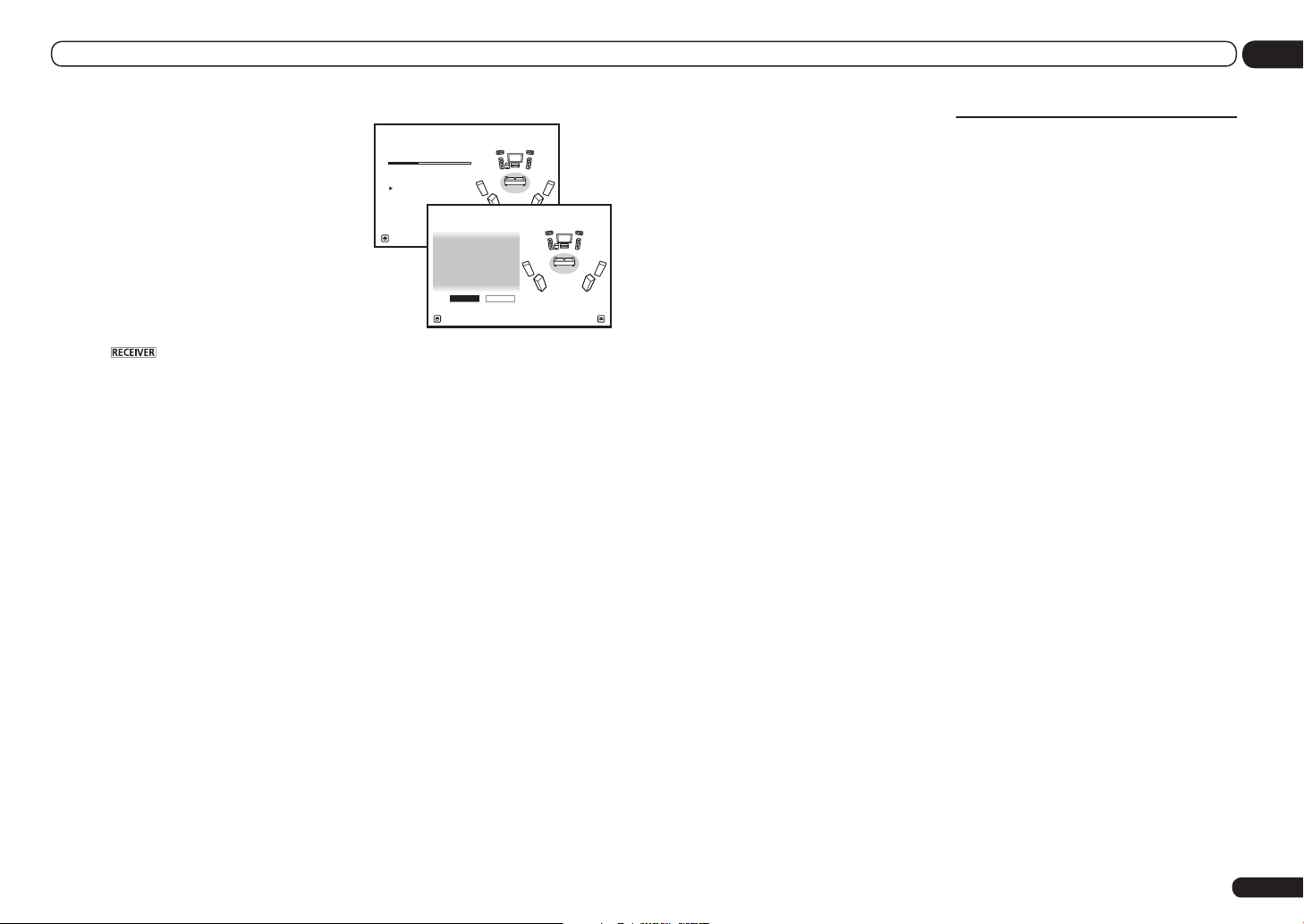
Basic Setup
04
sure to connect your speakers as necessary
before continuing to step 4.
! EQ Type – This determines how the
frequency balance is adjusted.
! MCACC – The six MCACC presets are used
for storing surround sound settings for
different listening positions. Simply choose
an unused preset for now (you can rename it
later in Data Management on page 67 ).
! THX Speaker – Select YES when using THX
speakers (all speakers other than the front
speakers are set to SMALL). In other cases,
leave at NO.
4 Press then select START.
5 Follow the instructions on-screen.
Make sure the microphone is connected, and
if you’re using a subwoofer, make sure it is
switched on and set to a comfortable volume
level.
6 Wait for the test tones to finish, then
confirm the speaker configuration in the
GUI screen.
A progress report is displayed on-screen while
the receiver outputs test tones to determine
the speakers present in your setup. Try to be as
quiet as possible while it’s doing this.
If no operations are performed for 10 seconds
while the speaker configuration check screen
is being displayed, the Full Auto MCACC Setup
will resume automatically. In this case, you
don’t need to select ‘OK’ and press ENTER in
step 7.
! With error messages (such as Too much
ambient noise! or Check microphone.),
select RETRY after checking for ambient
noise (see Problems when using the Auto
MCACC Setup on page 27 ) and verifying the
mic connection. If there doesn’t seem to be
a problem, you can simply select GO NEXT
and continue.
1a.Full Auto MCACC
Now Analyzin g... 2/10
Environmen t Check
A/V RECEIVER
Ambient No ise : OK
Microphone :
Speaker YES /NO :
Exit Cancel
1a.Full Auto MCACC
L : YES
FHL : YES
C : YE S
FHR : YES
R : YE S
SR : YES
SBR : YES
SBL : YES
SL : YES
SW : YE S
10
Exit Cancel
A/V RECEIVER
OK RE TRY
The configuration shown on-screen should
reflect the actual speakers you have.
! If you see an ERR message (or the speaker
configuration displayed isn’t correct),
there may be a problem with the speaker
connection. If selecting RETRY doesn’t work,
turn off the power and check the speaker
connections. If there doesn’t seem to be a
problem, you can simply use i/j to select
the speaker and k/l to change the setting
and continue.
! If the speaker is not pointed to the
microphone (listening position) or when
using speakers that affect the phase
(dipole speakers, reflective speakers, etc.),
Reverse Phase may be displayed even if the
speakers are properly connected.
If Reverse Phase is displayed, the speaker’s
wiring (+ and –) may be inverted. Check the
speaker connections.
— If the connections were wrong, turn off
the power, disconnect the power cord,
then reconnect properly. After this,
perform the Full Auto MCACC procedure
again.
— If the connections were right, select
GO NEXT and continue.
7 Make sure ‘OK’ is selected, then press
ENTER.
A progress report is displayed on-screen while
the receiver outputs more test tones to determine the optimum receiver settings.
Again, try to be as quiet as possible while this is
happening. It may take 3 to 10 minutes.
8 The Full Auto MCACC Setup procedure
is completed and the Home Menu menu
reappears automatically.
Be sure to disconnect the microphone from
this receiver upon completion of the Full Auto
MCACC Setup.
The settings made in the Full Auto MCACC
Setup should give you excellent surround
sound from your system, but it is also possible
to adjust these settings manually using The
Advanced MCACC menu on page 62 or The
System Setup and Other Setup menus on page
69 .
! Depending on the characteristics of your
room, sometimes identical speakers with
cone sizes of around 12 cm (5 inches) will
end up with different size settings. You
can correct the setting manually using the
Manual speaker setup on page 69 .
! The subwoofer distance setting may be
farther than the actual distance from the
listening position. This setting should
be accurate (taking delay and room
characteristics into account) and generally
does not need to be changed.
! If Full Auto MCACC Setup measurement
results are incorrect due to the interaction of
the speakers and viewing environment, we
recommend adjusting the settings manually.
Problems when using the Auto
MCACC Setup
If the room environment is not optimal for the
Auto MCACC Setup (too much background
noise, echo off the walls, obstacles blocking
the speakers from the microphone) the final
settings may be incorrect. Check for household
appliances (air conditioner, fridge, fan, etc.),
that may be affecting the environment and
switch them off if necessary. If there are any
instructions showing in the front panel display,
please follow them.
! Some older TVs may interfere with the
operation of the microphone. If this seems to
be happening, switch off the TV when doing
the Auto MCACC Setup.
En
27
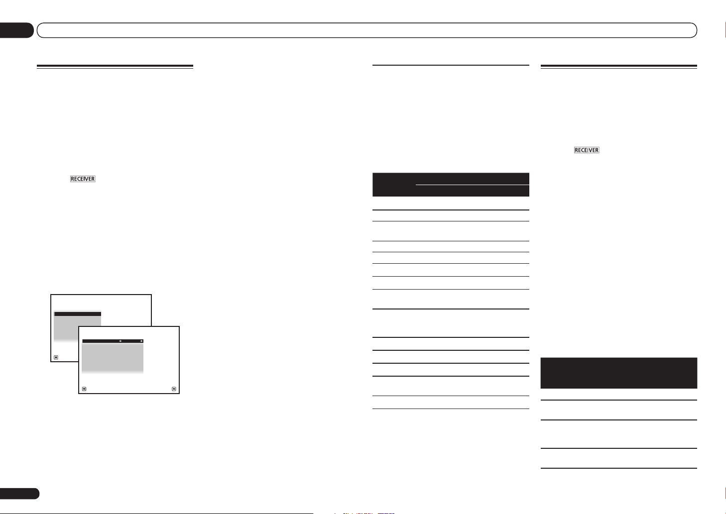
04 Basic Setup
The Input Setup menu
You only need to make settings in the
Input Setup menu if you didn’t hook up your
digital equipment according to the default
settings (see Input function default and possible
settings on page 28 ). In this case, you need to
tell the receiver what equipment is hooked up
to which terminal so the buttons on the remote
control correspond to the components you’ve
connected.
1 Press on the remote control,
then press HOME MENU.
A Graphical User Interface (GUI) screen
appears on your TV. Use i/j/k/l and
ENTER to navigate through the screens and
select menu items. Press RETURN to exit the
current menu.
2 Select ‘System Setup’ from the
Home Menu.
3 Select ‘Input Setup’ from the
System Setup menu.
4.System Setup
a.Ma nual SP S etup
b. Inpu t Set up
c. OSD Lang uage
d. Netw ork S etup
e. HDMI Set up
f. Othe r Set up
Exit Retu rn
4 Select the input function that you
want to set up.
The default names correspond with the names
next to the terminals on the rear panel (such as
DVD or BD) which, in turn, correspond with the
names on the remote control.
A/V RECEIVER
4b.Input Setup
Input : DVD
Input Name : Renam e
Input Skip : OFF
Digital In : COA X-1
HDMI Input : DVD
Component In : In-1
12V Trigger1 : OFF
12V Trigger2 : OFF
A/V RECEIVER
Exit Finish
5 Select the input(s) to which you’ve
connected your component.
For example, if your DVD player only has an
optical output, you will need to change the DVD
input function’s Digital In setting from COAX-1
(default) to the optical input you’ve connected
it to. The numbering (OPT-1 to OPT-2) corresponds with the numbers beside the inputs on
the back of the receiver.
6 When you’re finished, proceed to the
settings for other inputs.
There are optional settings in addition to the
assignment of the input jacks:
! Input Name – You can choose to rename the
input function for easier identification. Select
Rename to do so, or Default to return to the
system default.
! Input Skip – When set to ON, that input
is skipped when selecting the input using
INPUT SELECT. (DVD and other inputs can
be still be selected directly with the input
function buttons.)
! 12V Trigger1/2 – After connecting a
component to one of the 12 volt triggers (see
Switching components on and off using the
12 volt trigger on page 24 ), select MAIN,
ZONE 2, ZONE 3 (VSX-53 only) or OFF for the
corresponding trigger setting to switch it on
automatically along with the (main or sub)
zone specified.
— VSX-53 only:
Devices connected to 12 volt triggers can
be associated with HDMI OUT switching.
For details, see HDMI Setup on page 47 .
7 When you’re finished, press RETURN.
You will return to the System Setup menu.
Input function default and
possible settings
The terminals on the receiver generally correspond to the name of one of the input functions. If you have connected components to
this receiver differently from (or in addition to)
the defaults below, see The Input Setup menu
on page 28 to tell the receiver how you’ve
connected up. The dots (k) indicate possible
assignments.
Input
function
BD
DVD IN 5 COAX-1 IN 1
TV/SAT
DVR/BDR IN 6 OPT-2 IN 2
VIDEO IN 4 OPT-3
HDMI 1 IN 1
HDMI 2 IN 2
HDMI 3
(front panel)
HOME
MEDIA
GALLERY
iPod/USB
CD COAX-2
TUNER
ADAPTER
PORT
SIRIUS
a With Control with HDMI set to ON, assignments
cannot be made (see Control with HDMI function on
page 47 ).
Input Terminals
HDMI Digital Component
(BD)
k
<a>
IN 3
OPT-1
k
k
k
Operation Mode Setup
This receiver is equipped with a great number
of functions and settings. The Operation Mode
feature is provided for users who find it difficult
to master all these functions and settings.
One of two settings can be selected for the
Operation Mode: Expert and Basic.
1 Press on the remote control,
then press HOME MENU.
A Graphical User Interface (GUI) screen
appears on your TV. Use i/j/k/l and
ENTER to navigate through the screens and
select menu items. Press RETURN to exit the
current menu.
2 Select ‘Operation Mode Setup’ from
the Home Menu.
3 Select the Operation Mode setting you
want.
! Expert (default) – Users can set all the
functions by themselves.
! Basic – The number of operable functions is
restricted, and functions whose operations
are restricted are automatically set to achieve
the Pioneer-recommended sound and
picture quality. The functions that can be
operated are shown below. They can be set
as necessary by referring to the operating
instructions.
Operable
functions/
items
HOME MENU
Full Auto
MCACC
Input Name
Input Skip
Descriptions Page
Makes high precision
sound field settings easily.
Input names can be
changed as desired for
easier use.
Inputs not being used are
skipped (not displayed).
26
28
28
28
En

Basic Setup
04
Operable
functions/
items
Software
Update
Network
Information
Pairing
Bluetooth
Setup
Audio Parameters
MCACC
(MCACC
preset)
DELAY
(Sound Delay)
S.RTRV
(Auto Sound
Retriever)
DUAL
(Dual Mono)
V.SB
(Virtual Surround Back)
V.HEIGHT
(Virtual
Height)
V.DEPTH
(Virtual
Depth)
Other functions
INPUT
SELECT
(INPUT
SELECTOR)
MASTER
VOLUME +/–,
MUTE
LISTENING
MODE
PQLS
Descriptions Page
Updates to the latest version of the software.
Checks the receiver’s IP
address.
Pairs with a Bluetooth
device using AS-BT100 or
AS-BT200.
Selects your favorite
MCACC preset memory.
Adjusts the delay time of
the overall sound.
Plays compressed sound
with high sound quality. 50
Dual monaural audio
setting.
Creates a virtual surround
back channel sound for
playback.
Creates a virtual height
channel sound for playback.
Plays with a sound field
suited for 3D images.
Switches the input. 30
Use to set the listening
volume.
Only Pioneer-recommended
modes can be selected.
Plays using the PQLS
function.
74
73
35
50
50
50
50
50
50
30
37
48
Operable
functions/
Descriptions Page
items
PHASE CTRL
(Phase Control)
VSX-53 only:
PHASE CTRL
(Full Band
Phase Control)
iPod iPhone
iPad DIRECT
CONTROL
Plays with phase shifting in
the low range corrected.
The Full Band Phase
Control feature calibrates
the frequency-phase characteristics of the speakers
connected.
Switches the input to iPod/
USB and sets the mode
allowing operation from
the iPod.
39
39
31
4 When you’re finished, press RETURN.
You will return to the Home Menu.
En
29

05 Basic playback
Basic playback
Playing a source
Here are the basic instructions for playing a
source (such as a DVD disc) with your home
theater system.
1 Switch on your system components
and receiver.
Start by switching on the playback component (for example a DVD player), your TV and
subwoofer (if you have one), then the receiver
(press u RECEIVER).
Make sure that the TV’s video input is set to this
receiver.
2 Select the input function you want to
play.
You can use the input function buttons on the
remote control, INPUT SELECT, or the front
panel INPUT SELECTOR dial.
! If you need to manually switch the input
signal type press SIGNAL SEL (page 39).
3 Press to the receiver operation
mode.
4 Press AUTO/ALC/DIRECT
(AUTO SURR/ALC/STREAM DIRECT) to
select ‘AUTO SURROUND’ and start
playback of the source.
If you’re playing a Dolby Digital or DTS surround
sound source, you should hear surround sound.
If you are playing a stereo source, you will only
hear sound from the front left/right speakers in
the default listening mode.
! You may need to check the digital audio
output settings on your DVD player or digital
satellite receiver. It should be set to output
Dolby Digital, DTS and 88.2 kHz / 96 kHz PCM
(2 channel) audio, and if there is an MPEG
audio option, set this to convert the MPEG
audio to PCM.
En
30
! See also Listening to your system on page 37
for information on different ways of listening
to sources.
It is possible to check on the front panel display whether or not multi-channel playback is
being performed properly. For details, see Auto
Surround, ALC and Stream Direct with different
input signal formats on page 90 .
When using a surround back speaker,
2DIGITAL is displayed when playing Dolby
Digital 5.1 channel signals, and DTS is displayed when playing DTS 5.1-channel signals.
If the display does not correspond to the input
signal and listening mode, check the connections and settings.
5 Use the MASTER VOLUME +/– to adjust
the volume level.
Turn down the volume of your TV so that all
sound is coming from the speakers connected
to this receiver.
Playing a source with HDMI
connection
% Use INPUT SELECT to select the input
function connected to the receiver’s HDMI
input terminals.
You can also perform the same operation by
using the INPUT SELECTOR dial on the front
panel or by pressing HDMI on the remote control repeatedly.
! Set the HDMI parameter in Setting the Audio
options on page 50 to THROUGH if you want
to hear HDMI audio output from your TV (no
sound will be heard from this receiver).
! If the video signal does not appear on your
TV, try adjusting the resolution settings on
your component or display. Note that some
components (such as video game units) have
resolutions that may not be converted. In this
case, use an analog video connection.
Playing an iPod
This receiver has the iPod iPhone iPad USB
terminal that will allow you to control playback
of audio content from your iPod using the controls of this receiver.
! This receiver is compatible with the audio
and video of the iPod nano (audio only for the
iPod nano 1G/2G), iPod fifth generation (audio
only), iPod classic, iPod touch, iPhone and
iPad. However, some of the functions may be
restricted for some models. The receiver is not
compatible with the iPod shuffle.
! This receiver has been developed and tested
for the software version of iPod/iPhone/iPad
indicated on the website of Pioneer (http://
pioneer.jp/homeav/support/ios/na/).
! Installing software versions other than
indicated on the website of Pioneer to your
iPod/iPhone/iPad may result in incompatibility
with this receiver.
! iPod, iPhone and iPad are licensed for
reproduction of non-copyrighted materials
or materials the user is legally permitted to
reproduce.
! Features such as the equalizer cannot
be controlled using this receiver, and we
recommend switching the equalizer off before
connecting.
! Pioneer cannot under any circumstances
accept responsibility for any direct or indirect
loss arising from any inconvenience or loss
of recorded material resulting from the iPod
failure.
! When listening to a track on the iPod in the
main zone, it is possible to control the sub
zone, but not to listen to a different track in
the sub zone from the one playing in the main
zone.
1 Press u RECEIVER to switch on the
receiver and your TV.
See Connecting an iPod on page 23 .
! It is also possible to operate the iPod on the
iPod itself, without using the TV screen. For
details, see Switching the iPod controls on
page 31 .
2 Press iPod USB on the remote control
to switch the receiver to the iPod/USB.
Loading appears in the GUI screen while the
receiver verifies the connection and retrieves
data from the iPod.
When the display shows the iPod Top menu
you’re ready to play music from the iPod.
! The controls of your iPod will be inoperable
when connected to this receiver.
Playing back audio files stored on
an iPod
To navigate songs on your iPod, you can take
advantage of the GUI screen of your TV connected to this receiver. You can also control all
operations for music in the front panel display
of this receiver.
! Note that characters that cannot be displayed
on this receiver are displayed as #.
! This feature is not available for photos on your
iPod. To display photos, switch iPod operation
to the iPod (see Switching the iPod controls on
page 31 ).
Finding what you want to play
When your iPod is connected to this receiver,
you can browse songs stored on your iPod by
playlist, artist name, album name, song name,
genre or composer, similar to using your iPod
directly.
1 Use i/j to select ‘Music’ from the
iPod Top menu.
 Loading...