


AUDIO/VIDEO MULTI-CHANNEL RECEIVER
SINTOAMPLIFICATORE AUDIO/VIDEO MULTICANALE
VSX-415-S/-K VSX-515-S/-K
Operating Instructions
Istruzioni per l’uso
IMPORTANT
CAUTION
RISK OF ELECTRIC SHOCK
DO NOT OPEN
The lightning flash with arrowhead symbol, within an equilateral triangle, is intended to alert the user to the presence of uninsulated "dangerous voltage" within the product's enclosure that may be of sufficient magnitude to constitute a risk of electric shock to persons.
CAUTION:
TO PREVENT THE RISK OF ELECTRIC SHOCK, DO NOT REMOVE COVER (OR BACK). NO USER-SERVICEABLE PARTS INSIDE. REFER SERVICING TO QUALIFIED SERVICE PERSONNEL.
The exclamation point within an equilateral triangle is intended to alert the user to the presence of important operating and maintenance (servicing) instructions in the literature accompanying the appliance.
D3-4-2-1-1_En-A
Replacement and mounting of an AC plug on the power supply cord of this unit should be performed only by qualified service personnel.
IMPORTANT |
The cut-off plug should be disposed of and must |
Do not connect either wire to the earth terminal of a |
||
not be inserted into any 13 amp socket as this can |
three pin plug. |
|||
result in electric shock. The plug or adaptor or the |
NOTE |
|||
FOR USE IN THE UNITED |
distribution panel should be provided with 5 A fuse. |
|||
As the colours of the wires in the mains lead of this |
After replacing or changing a fuse, the fuse cover in |
|||
KINGDOM |
||||
appliance may not correspond with coloured |
the plug must be replaced with a fuse cover which |
|||
The wires in this mains lead are coloured in |
markings identifying the terminals in your plug, |
corresponds to the colour of the insert in the base |
||
accordance with the following code: |
proceed as follows ; |
of the plug or the word that is embossed on the |
||
Blue |
: Neutral |
The wire which is coloured blue must be connected |
base of the plug, and the appliance must not be |
|
Brown |
: Live |
to the terminal which is marked with the letter N or |
used without a fuse cover. If lost replacement fuse |
|
If the plug provided is unsuitable for your socket |
coloured black. |
covers can be obtained from your dealer. |
||
outlets, the plug must be cut off and a suitable plug |
The wire which is coloured brown must be |
Only 5 A fuses approved by B.S.I or A.S.T.A to |
||
fitted. |
|
connected to the terminal which is marked with the |
B.S.1362 should be used. |
|
|
|
letter L or coloured red. |
D3-4-2-1-2-2_En |
|
Thank you for buying this Pioneer product.
Please read through these operating instructions so you will know how to operate your model properly. After you have finished reading the instructions, put them away in a safe place for future reference.
WARNING
This equipment is not waterproof. To prevent a fire or shock hazard, do not place any container filed with liquid near this equipment (such as a vase or flower pot) or expose it to dripping, splashing, rain or moisture.
WARNING
Before plugging in for the first time, read the following section carefully.
The voltage of the available power supply differs according to country or region. Be sure that the power supply voltage of the area where this unit will be used meets the required voltage (e.g., 230V or 120V) written on the rear panel.
WARNING
To prevent a fire hazard, do not place any naked flame sources (such as a lighted candle) on the equipment.
Operating Environment
Operating environment temperature and humidity: +5 ºC – +35 ºC (+41 ºF – +95 ºF); less than 85 %RH (cooling vents not blocked)
Do not install this unit in a poorly ventilated area, or in locations exposed to high humidity or direct sunlight (or strong artificial light)
This product complies with the Low Voltage Directive (73/23/EEC, amended by 93/68/EEC), EMC Directives (89/336/EEC, amended by 92/31/EEC and 93/68/EEC).
VENTILATION CAUTION
When installing this unit, make sure to leave space around the unit for ventilation to improve heat radiation (at least 60 cm at top, 10 cm at rear, and 30 cm at each side).
WARNING
Slots and openings in the cabinet are provided for ventilation to ensure reliable operation of the product, and to protect it from overheating. To prevent fire hazard, the openings should never be blocked or covered with items (such as newspapers, table-cloths, curtains) or by operating the equipment on thick carpet or a bed.
This product is for general household purposes. Any failure due to use for other than household purposes (such as long-term use for business purposes in a restaurant or use in a car or ship) and which requires repair will be charged for even during the warranty period.
Manufactured under license from Dolby Laboratories. "Dolby", "Pro Logic", "Surround EX", and the double-D symbol are trademarks of Dolby Laboratories.
"DTS" ,"DTS-ES Extended Surround" and "Neo:6" are trademarks of Digital Theater Systems, Inc.
If the AC plug of this unit does not match the AC outlet you want to use, the plug must be removed and appropriate one fitted. Replacement and mounting of an AC plug on the power supply cord of this unit should be performed only by qualified service personnel. If connected to an AC outlet, the cut-off plug can cause severe electrical shock. Make sure it is properly disposed of after removal.
The equipment should be disconnected by removing the mains plug from the wall socket when left unused for a long period of time (for example, when on vacation).
CAUTION
The STANDBY/ON switch on this unit will not completely shut off all power from the AC outlet. Since the power cord serves as the main disconnect device for the unit, you will need to unplug it from the AC outlet to shut down all power. Therefore, make sure the unit has been installed so that the power cord can be easily unplugged from the AC outlet in case of an accident. To avoid fire hazard, the power cord should also be unplugged from the AC outlet when left unused for a long period of time (for example, when on vacation).

Contents
01 Before you start
Checking what’s in the box . . . . . . . . . . . . . . . 6
Loading the batteries . . . . . . . . . . . . . . . . . . . 6
Operating range of remote control unit. . . . . . 6 Installing the receiver . . . . . . . . . . . . . . . . . . . 6
02 5 minute guide
Introduction to home theater . . . . . . . . . . . . . 7 Listening to Surround Sound . . . . . . . . . . . . . 8
Using the Quick Setup . . . . . . . . . . . . . . . . . 11
03 Quick surround sound setup
Automatically setting up for surround
sound (MCACC) . . . . . . . . . . . . . . . . . . . . . . 13
Other problems during Auto MCACC . . . . . 14
04 Connecting up
Making cable connections . . . . . . . . . . . . . . 15
Analog audio cables. . . . . . . . . . . . . . . . . . 15 Digital audio cables . . . . . . . . . . . . . . . . . . 15 Video cables . . . . . . . . . . . . . . . . . . . . . . . . 15
Connecting a DVD player and TV . . . . . . . . . 16 Connecting the multichannel analog
outputs. . . . . . . . . . . . . . . . . . . . . . . . . . . . 17
Connecting a satellite receiver or other
digital set-top box . . . . . . . . . . . . . . . . . . . . . 17
Connecting other audio components . . . . . . 18 About the WMA9 Pro decoder . . . . . . . . . . 18 Connecting other video components . . . . . . 19
Connecting antennas . . . . . . . . . . . . . . . . . . 20 FM wire antenna. . . . . . . . . . . . . . . . . . . . . 20 AM loop antenna . . . . . . . . . . . . . . . . . . . . 20
Using external antennas. . . . . . . . . . . . . . . 20 Connecting the speakers (VSX-415) . . . . . . . 21 Connecting the speakers (VSX-515) . . . . . . . 22
Speaker terminals . . . . . . . . . . . . . . . . . . . 23
Hints on speaker placement. . . . . . . . . . . . 23 Speaker placement diagrams. . . . . . . . . . . 23
05 Controls and displays
Front panel . . . . . . . . . . . . . . . . . . . . . . . . . . 25 Display . . . . . . . . . . . . . . . . . . . . . . . . . . . . . 27 VSX-515 model: . . . . . . . . . . . . . . . . . . . . . 27 VSX-415 model: . . . . . . . . . . . . . . . . . . . . . 27 Remote control . . . . . . . . . . . . . . . . . . . . . . . 29
06 Listening to your system
Auto playback . . . . . . . . . . . . . . . . . . . . . . . . 31
Listening in surround sound . . . . . . . . . . . . . 31 Using the Advanced surround effects . . . . 32
Listening in stereo. . . . . . . . . . . . . . . . . . . . . 34
Listening with Acoustic Calibration EQ . . . . . 34 Choosing the input signal . . . . . . . . . . . . . . . 35
Using the surround back channel
(Extended mode) . . . . . . . . . . . . . . . . . . . . . . 36
Using the Virtual Surround Back
mode (VSB) . . . . . . . . . . . . . . . . . . . . . . . . . . 37
Using Midnight and Loudness listening . . . . 38
Enhancing dialog . . . . . . . . . . . . . . . . . . . . . 38
Using the tone controls . . . . . . . . . . . . . . . . . 38
Playing other sources . . . . . . . . . . . . . . . . . . 39
Selecting the multichannel analog inputs . . . 39
Using the sleep timer . . . . . . . . . . . . . . . . . . 39
07 Setting up the receiver
Choosing your receiver setup . . . . . . . . . . . . 40 Surround and sound setup options . . . . . . . . 41
Speaker setting . . . . . . . . . . . . . . . . . . . . . . 41 Subwoofer setting. . . . . . . . . . . . . . . . . . . . 41
Crossover frequency setting . . . . . . . . . . . . 41 LFE attenuator setting. . . . . . . . . . . . . . . . . 41 Front speaker distance setting . . . . . . . . . . 42 Center speaker distance setting . . . . . . . . . 42 Surround speaker distance setting . . . . . . . 42 Subwoofer distance setting. . . . . . . . . . . . . 42 Dynamic range control setting . . . . . . . . . . 42
Dual mono setting . . . . . . . . . . . . . . . . . . . 42
Digital input settings. . . . . . . . . . . . . . . . . . 43 Setting separate channel levels for
listening modes. . . . . . . . . . . . . . . . . . . . . . . 43
08 The System Setup menu
Making receiver settings from the System Setup menu. . . . . . . . . . . . . . . . . . . . . . . . . . 44
Manual MCACC speaker setup . . . . . . . . . . . 44
Fine Channel Level . . . . . . . . . . . . . . . . . . . 45
Fine Channel Distance . . . . . . . . . . . . . . . . 46 Acoustic Calibration EQ . . . . . . . . . . . . . . . 46
Manual speaker setup . . . . . . . . . . . . . . . . . . 48 Speaker setting . . . . . . . . . . . . . . . . . . . . . . 48 Crossover network . . . . . . . . . . . . . . . . . . . 49 Channel level . . . . . . . . . . . . . . . . . . . . . . . 50 Speaker Distance . . . . . . . . . . . . . . . . . . . . 50
The Input Assign menu . . . . . . . . . . . . . . . . . 51 The Other setup menu. . . . . . . . . . . . . . . . . . 51
Dynamic Range Control Setup . . . . . . . . . . 51
Dual Mono Setup . . . . . . . . . . . . . . . . . . . . 52 LFE Attenuator Setup . . . . . . . . . . . . . . . . . 52
09 Using the tuner
Listening to the radio. . . . . . . . . . . . . . . . . . . 53
Improving FM stereo sound . . . . . . . . . . . . 53 Saving station presets . . . . . . . . . . . . . . . . . . 53 Naming station presets. . . . . . . . . . . . . . . . 54 Listening to station presets . . . . . . . . . . . . . 54 An introduction to RDS . . . . . . . . . . . . . . . . . 55 Displaying RDS information . . . . . . . . . . . . 55 Searching for RDS programs . . . . . . . . . . . 55
Using EON . . . . . . . . . . . . . . . . . . . . . . . . . . 56
Clearing all stations from the RDS and
EON searches. . . . . . . . . . . . . . . . . . . . . . . 56

10 Making recordings
Making an audio or a video recording . . . . . . 57
11 Additional information
Troubleshooting . . . . . . . . . . . . . . . . . . . . . . 58
Resetting the main unit . . . . . . . . . . . . . . . . . 61 Switching the speaker impedance. . . . . . . . . 61
Specifications . . . . . . . . . . . . . . . . . . . . . . . . 62 Power cord caution . . . . . . . . . . . . . . . . . . . . 63 Cleaning the unit. . . . . . . . . . . . . . . . . . . . . . 63
Nederlands Deutsch Français Italiano English
Español
01 Before you start
Chapter 1:
Before you start
Checking what’s in the box
Please check that you've received the following supplied accessories:
•AM loop antenna
•FM wire antenna
•Dry cell batteries (AA size IEC R6) x2
•Remote control
•Setup microphone (VSX-515 model only)
•These operating instructions
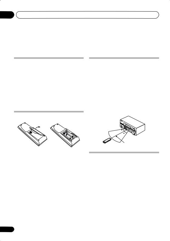
Operating range of remote control unit
The remote control may not work properly if:
•There are obstacles between the remote control and the receiver's remote sensor.
•Direct sunlight or fluorescent light is shining onto the remote sensor.
•The receiver is located near a device that is emitting infrared rays.
•The receiver is operated simultaneously with another infrared remote control unit.
Loading the batteries
30
30
7m
 Important
Incorrect use of batteries may result in such hazards as leakage and bursting. Observe the following precautions:
•Never use new and old batteries together.
•Insert the plus and minus sides of the batteries properly according to the marks in the battery case.
•Batteries with the same shape may have different voltages. Do not use different batteries together.
•When disposing of used batteries, please comply with governmental regulations or environmental public instruction’s rules that apply in your country or area.
6
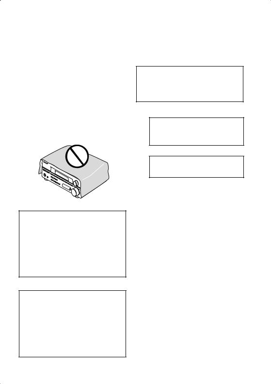
Installing the receiver
•When installing this unit, make sure to put it on a level and stable surface.
Don’t install it on the following places:
–on a color TV (the screen may distort)
–near a cassette deck (or close to a device that gives off a magnetic field). This may interfere with the sound.
–in direct sunlight
–in damp or wet areas
–in extremely hot or cold areas
–in places where there is vibration or other movement
–in places that are very dusty
–in places that have hot fumes or oils (such as a kitchen)
En

5 minute guide
Chapter 2:
5 minute guide
Introduction to home theater
You are probably used to using stereo equipment to listen to music, but may not be used to home theater systems that give you many more options (such as surround sound) when listening to soundtracks.
Home theater refers to the use of multiple audio tracks to create a surround sound effect, making you feel like you're in the middle of the action or concert. The surround sound you get from a home theater system depends not only on the speakers you have set up in your room, but also on the source and the sound settings of the receiver.
DVD-Video has become the basic source material for home theater due to its size, quality, and ease of use. Depending on the DVD, you can have up to seven different audio tracks coming from one disc, all of them being sent to different speakers in your system. This is what creates a surround sound effect and gives you the feeling of ‘being there’.
This receiver will automatically decode Dolby Digital, DTS, or Dolby Surround DVD-Video discs, according to your speaker setup. In most cases, you won’t have to make changes for realistic surround sound, but other possibilities (like listening to a CD with multichannel surround sound) are explained in Listening to your system on page 31.
02
Español Nederlands Italiano Français Deutsch English
7
En
02 5 minute guide
Listening to Surround Sound
This receiver was designed with the easiest possible setup in mind, so with the following quick setup guide, you should have your system hooked up for surround sound in no time at all. In most cases, you can simply leave the receiver in the default settings.
Be sure to complete all connections before connecting this unit to the AC power source.
1 Hook up your DVD player.
For surround sound, you’ll want to hook up using a digital connection from the DVD player to the receiver. You can do this with either a coaxial, or an optical connection (you don’t need to connect both). If you hook up using an optical cable, you will need to assign the optical input to DVD (for the VSX-415 see Digital input settings on page 43 and for the VSX-515 see The Input Assign menu on page 51).
Use a video cord to connect the video output on your DVD player to the receiver using the jacks shown below.
2 Hook up your TV.
Use a video cord to connect your receiver to the TV using the jacks as shown below.
Optical cable
VIDEO IN
TV
DIGITAL OUT |
Coaxial |
|
|
OPT |
|
|
cable |
1 |
|
|
|
|
(TV/SAT) |
|
|
ASSIGNABLE |
COAX |
|
DIGITAL IN |
|
|
|
2 |
|
|
(CD) |
|
|
COAX |
|
|
1 |
0 |
3 |
(DVD |
7 |
8 |
|
|
|
/LD) |
|
R |
AUDIO L |
|
|
|
FM UNBAL |
AM |
|
IN |
75 Ω |
LOOP ANTENNA |
|
CD |
|
|
|
OUT |
DVR/ |
|
|
|
VCR |
|
OPT |
IN |
VIDEO |
|
1 |
|
IN |
|
|
|
TV / |
OUT |
(TV/SAT) |
IN |
SAT |
|
|
|
DVD |
IN |
|
|
|
|
/LD |
|
MONITOR |
ASSIGNABLE |
|
IN |
FRONT |
|
OUT |
DIGITAL IN |
COAX |
|
|
D V D |
|
|
2 |
|
|
5.1CH |
SUB |
|
(CD) |
|
REC |
INPUT |
WOOFER |
|
COAX |
OUT |
CD-R |
IN |
PREOUT |
|
|
/TAPE |
|
|
|
|
1 |
|
/MD |
|
|
|
(DVD |
IN |
PLAY |
|
|
|
/LD) |
|
|
DVD player
VIDEO OUT |
DVD |
IN |
/ LD |
|
|
|
FRONT |
|
S |
|
D V D |
REC |
5.1CH |
|
|
INPUT |
|
/ |
CD-R |
IN |
TAPE |
|
|
|
/ MD |
|
Video cord
This receiver*
CENSUB
TER WOOFER
R 
 L
L
SURROUND
DVD 5.1CH INPUT
S |
|
VIDEO |
|
|
|
|
|
|
|
|
R |
FRONT |
L |
CENTER |
R SURROUND BACK |
L |
R |
SURROUND |
L |
||
P |
|
|
|
OUT |
|
|
|
|
|
|
E |
|
|
|
|
|
|
|
|
|
|
A |
|
|
|
|
|
SINGLE |
|
|
|
|
K IN |
|
|
|
|
|
SEEINSTRUCTION |
|
|
|
|
|
|
|
MONITOR |
MANUAL |
|
|
|
|
||
E |
|
|
|
OUT |
|
|
|
|
|
|
R |
|
|
|
|
|
|
|
|
|
|
S |
|
|
|
SUB |
|
|
|
|
|
|
|
|
|
|
|
|
|
|
|
|
|
|
|
|
|
WOOFER |
|
|
|
|
|
|
|
|
|
|
PREOUT |
|
|
|
|
|
|
Video cord
* The illustration shows the VSX-515, but connections for the VSX-415 are the same.
8
En
5 minute guide |
02 |
3 Connect your speakers.
A complete setup of speakers is shown here (six speakers for the VSX-415, and eight for the VSX-
515), but home setups may vary. Simply connect the speakers you have as shown below.1 The receiver will work with just two stereo speakers (the front speakers in the diagram) but using at least three speakers is recommended, and a complete setup is best.
Make sure you connect the speaker on the right to the right terminal and the speaker on the left to the left terminal. Also make sure the positive and negative (+/–) terminals on the receiver match those on the speakers. You can use speakers with a nominal impedance between 6–16Ω (please see Switching the speaker impedance on page 61 if you plan to use speakers with an impedance of less than 8Ω).
Front speakers |
Center speaker |
Surround speakers |
||
L |
R |
C |
LS |
RS |
|
|
|
|
|
|
TERCEN- |
SUB WOOFER |
|
|
|
R |
AUDIO L |
|
|
|
|
|
|
|
|
|
|
FM UNBAL |
AM |
|
|
|
|
|
|
IN |
CD |
75 Ω |
LOOP ANTENNA |
R |
|
L |
|
|
|
|
|
|
|
|
SURROUND |
|
|
|
|
OUT |
DVR/ |
|
|
|
DVD 5.1CH INPUT |
|
|
|
|
|
VCR |
|
|
|
|
|
|
|
DIGITAL IN |
IN |
|
|
|
|
|
|
|
|
OPT |
|
VIDEO |
|
|
|
|
|
|
|
|
|
|
|
S |
R FRONT L |
CENTER |
R SURROUND L |
||
1 |
|
TV / |
IN |
OUT |
|
||||
(TV / |
IN |
SAT |
|
|
|
P |
|
|
|
SAT) |
|
IN |
|
|
|
|
|
||
ASSIGNABLE COAX |
|
DVD |
|
|
E |
|
|
|
|
|
|
MONITOR |
|
|
|
|
|||
2 |
|
/LD |
|
OUT |
|
A |
|
|
|
(CD) |
IN |
FRONT |
D V D |
|
|
|
|
||
COAX |
|
REC |
5.1CH |
SUB |
|
K |
|
|
|
1 |
|
INPUT |
WOOFER |
|
E |
|
|
|
|
OUT |
CD-R |
IN |
PREOUT |
|
|
|
|
||
(DVD |
/TAPE |
|
|
|
|
|
|||
/LD) |
|
/MD |
|
|
|
R |
|
|
|
|
IN |
PLAY |
|
|
|
S |
|
|
|
Powered subwoofer |
VSX-415 |
SW |
|
INPUT
 Note
Note
1VSX-415 model only
•If you’re not using a subwoofer, change the front speaker setting (see Speaker setting on page 41) to large.
VSX-515 model only
•If you’re not using a subwoofer, change the front speaker setting (see Speaker setting on page 48) to LARGE.
•If you are using only one surround back speaker, connect the positive wire to the right channel (+) terminal, and the negative wire to the left channel (–) terminal as shown.
Español Nederlands Italiano Français Deutsch English
9
En
02 5 minute guide
Front speakers |
Center speaker |
Surround speakers |
Surround back speakers |
|||||||||||
L |
|
R |
|
C |
LS |
|
RS |
|
SBL |
SBR |
||||
|
|
|
|
|
|
|
|
|
|
|
|
|
|
|
|
|
|
|
|
|
|
CEN- |
SUB |
|
|
|
|
|
|
|
|
|
|
TER |
WOOFER |
|
|
|
|
|
R |
AUDIO L |
|
|
|
|
|
|
|
|
|
|
|
|
FM UNBAL |
AM |
|
|
|
|
|
|
|
|
IN |
CD |
75 Ω |
LOOP |
ANTENNA |
R |
L |
|
|
|
|
|
|
|
|
|
|
|
||||
|
|
|
|
|
|
|
SURROUND |
|
|
|
|
|
|
OUT |
DVR/ |
|
|
|
DVD 5.1CH INPUT |
|
|
|
|
|
|
|
|
|
|
|
|
|
|
||
|
|
|
VCR |
|
|
|
|
|
|
|
|
|
OPT |
IN |
|
VIDEO |
|
|
|
|
|
|
|
|
1 |
|
TV / |
IN |
|
|
|
R FRONT L |
CENTER |
R SURROUND BACK L |
R SURROUND L |
|
|
|
|
OUT |
|
S |
|||||
(TV/SAT) |
IN |
SAT |
|
|
|
||||||
|
|
|
DVD |
IN |
|
|
P |
|
|
|
|
|
|
|
|
MONITOR |
|
|
|
|
|
||
|
|
|
/LD |
|
|
E |
|
|
|
|
|
ASSIGNABLE |
|
IN |
FRONT |
|
OUT |
|
|
|
|
|
|
COAX |
D V D |
|
|
|
|
|
|
||||
DIGITAL IN |
|
|
|
|
A |
|
|
SINGLE |
|
||
|
2 |
|
|
5.1CH |
SUB |
|
|
|
|
||
|
(CD) |
|
REC |
INPUT |
WOOFER |
|
K |
|
|
SEEINSTRUCTION |
|
|
|
CD-R |
IN |
PREOUT |
|
|
|
MANUAL |
|
||
|
COAX |
OUT |
|
|
|
|
|
||||
|
|
/TAPE |
|
|
|
E |
|
|
|
|
|
|
1 |
|
/MD |
|
|
|
|
|
|
|
|
|
|
|
|
|
|
R |
|
|
|
|
|
|
(DVD |
IN |
PLAY |
|
|
|
|
|
|
|
|
|
/LD) |
|
|
|
|
|
|
|
|||
|
|
|
|
|
|
|
S |
|
|
|
|
VSX-515
|
Single |
|
Powered subwoofer |
surround |
|
SW |
back |
|
speaker |
||
|
||
INPUT |
|
4 Plug in the receiver and switch it on, followed by your DVD player, subwoofer and TV.
Make sure you’ve set the video input on your TV to this receiver. Check the manual that came with the TV if you don’t know how to do this.
Also make sure that DVD/LD is showing in the receiver’s display, indicating that the DVD input is selected. If it isn’t, press DVD on the remote control to set the receiver to the DVD input.
5Press QUICK SETUP on the front panel to specify your speaker setup, room size and listening position.
Use the MULTI JOG dial to select and ENTER to confirm your selection. See Using the Quick Setup on page 11 if you’re unsure about the settings.
6Play a DVD, and adjust the volume to your liking.
There are several other sound options you can select. See Listening to your system on page 31 for
more on this.1 See also Choosing your receiver setup on page 40 (VSX-415) or The System Setup menu on page 44 (VSX-515) for more setup options.
 Note
Note
1 Depending on your DVD player or source discs, you may only get digital 2 channel stereo and analog sound. In this case, the listening mode must be set to STANDARD (it should already be set—see Listening in surround sound on page 31 if you need to do this) if you want multichannel surround sound.
10
En
5 minute guide
Using the Quick Setup
You can use the Quick Setup to get your system up and running with just a few button presses. The receiver automatically makes the necessary settings after you have selected your speaker setup, room size and listening position.
•VSX-515 only – If you want a more complete setup option, refer to Automatically setting up for surround sound (MCACC) on
page 13. If you choose to do so, you can skip the Quick Setup.
If you want to make more specific settings, refer to Choosing your receiver setup on
page 40 (VSX-415) or The System Setup menu on page 44 (VSX-515).
Use the front panel controls for the steps below.
AUDIO/VIDEO MULTI-CHANNEL RECEIVER VSX-515
MULTI JOG
ENTER
CD |
CD-R/TAPE/MD |
FM |
AM |
MASTER
VOLUME
MCACC
SETUP MIC
DOWN |
UP |
1If the receiver is off, press STANDBY/ON to turn the power on.
2Press QUICK SETUP.
•VSX-515 model only – SW DET flashes in the display while the receiver checks your setup for a subwoofer. SW YES or SW NO confirms the subwoofer check, then the display prompts you to select your speaker setup.
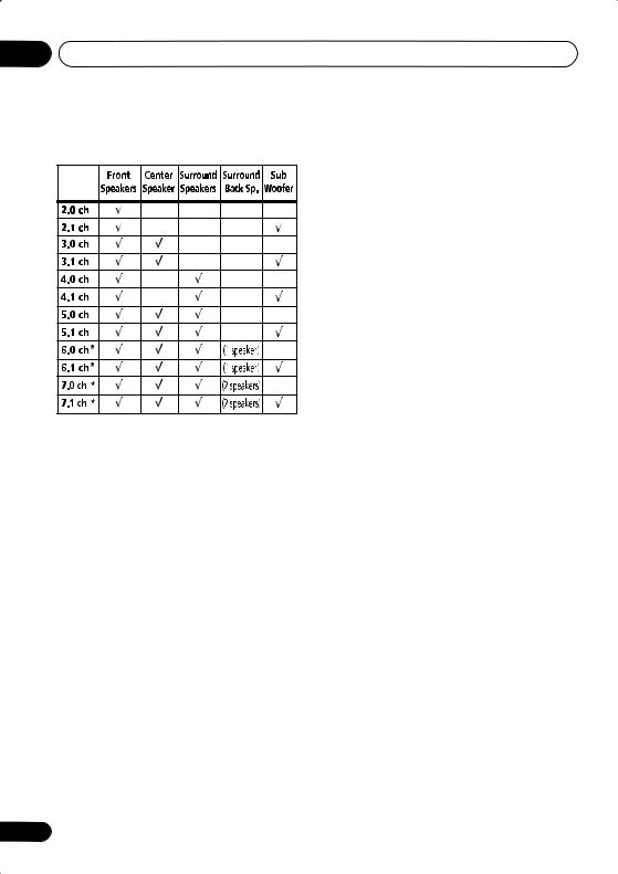
3Use the MULTI JOG dial to choose your speaker setup.
VSX-415 model:
The following choices are available:
2.0ch |
2.1ch |
3.0ch |
5.1ch |
|
3.1ch |
5.0ch |
4.1ch |
4.0ch |
VSX-515 model:
When a subwoofer was detected in step 2, the following choices are available:
2.1ch 3.1ch
7.1ch |
4.1ch |
6.1ch 5.1ch
If a subwoofer wasn’t detected in step 2, you can cycle between the following choices:
2.0ch 3.0ch
7.0ch |
4.0ch |
6.0ch 5.0ch
ADVANCED |
ST/DIRECT |
SIGNAL |
DVD/LD |
DVD 5.1 |
TV/SAT |
DVR/VCR |
|||
STANDARD SURR |
/AUTO SURR |
SELECT |
|||||||
LISTENING MODE |
|
|
|
|
|
|
|
|
|
|
|
|
EON |
PTY |
SPEAKER |
EXTENDED |
ACOUSTIC |
|
|
|
|
|
MODE |
SEARCH |
IMPEDANCE |
MODE |
EQ |
|
|
STANDBY/ON |
|
|
|
|
|
|
|
|
|
|
|
|
|
MULTI JOG |
|
|
|
|
|
|
PHONES |
|
TUNING |
TUNER |
|
QUICK |
SYSTEM |
|
|
|
|
|
|
|
RETURN |
||||
|
|
|
CLASS |
/STATION |
EDIT |
TONE |
SETUP |
SETUP |
|
MULTI JOG
02
Español Nederlands Italiano Français Deutsch English
* Illustration shows the VSX-515 model
11
En
025 minute guide
•Check the table below to find the speaker setup that corresponds with your system.
* VSX-515 model only
4Press ENTER.
5Use the MULTI JOG dial to choose your room size.
Depending on the distance of your speakers from the listening position, choose between small, medium, or large (S, M or L), M being an average-sized room.
6Press ENTER.
7Use the MULTI JOG dial to choose your listening position.
You can cycle between the following choices:
•FWD – If you are nearer to the front speakers than the surround speakers
•MID – If you are equal distance from the front and surround speakers
•BACK – If you are nearer to the surround speakers than the front speakers
8Press ENTER to confirm your setup.
The display shows the speaker setup, room size and listening position that you have selected.
12
En
Quick surround sound setup
Chapter 3:
Quick surround sound setup
VSX-515 model only
03
English
Automatically setting up for surround sound (MCACC)
The Auto Multi-Channel Acoustic Calibration (MCACC) setup measures the acoustic characteristics of your listening area, taking into account ambient noise, speaker size and distance, and tests for both channel delay and channel level. After you have set up the microphone provided with your system, the receiver uses the information from a series of test tones to optimize the speaker settings and equalization for your particular room.
 Important
•The Auto MCACC Setup will overwrite any existing speaker settings you’ve made.
•Make sure the headphones are unplugged.
 Caution
•The test tones used in the Auto MCACC Setup are output at high volume.
|
|
|
ADVANCED |
MIDNIGHT/ |
|
|
|
STANDARD SURROUND STEREO |
LOUDNESS |
RECEIVER SLEEP FL DIMMER INPUT ATT |
TOP MENU |
MENU |
||
|
|
|||
|
|
|
SYSTEM |
RETURN |
INPUT SELECTOR |
|
SETUP |
|
|
DVD/LD DVD 5.1CH |
TV/SAT |
DVR/VCR |
ENTER |
RECEIVER |
|
|
|
DVD |
|
CD-R/ |
FM |
AM |
|
|
CD TAPE/MD |
RECEIVER CONTROL |
|
||
|
|
|
|
|
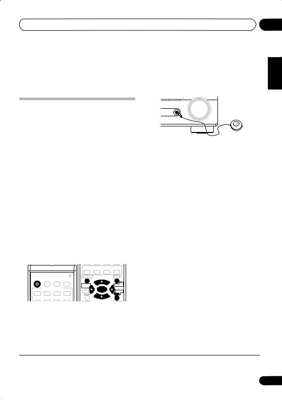
1 Connect the microphone to the MCACC SETUP MIC jack on the front panel.
Make sure there are no obstacles between the speakers and the microphone.
FM |
AM |
|
MASTER |
|
VOLUME |
|
MCACC |
|
SETUP MIC |
DOWN |
UP |
If you have a tripod, use it to place the microphone so that it’s about ear level at your normal listening position. Otherwise, place the microphone at ear level using a table or a chair.
2 If the receiver is off, press RECEIVER to turn the power on.
3If you have a subwoofer, turn it on.
4Press RECEIVER on the remote control, then press the SYSTEM SETUP button.
•Press SYSTEM SETUP again at any time to exit the System Setup menu.1
5Select ‘A. MCACC’ from the System Setup menu then press ENTER.
Try to be as quiet as possible after pressing ENTER. The system outputs a series of test tones to establish the ambient noise level.
If the noise level is too high, NOISY! blinks in the display for five seconds. To exit and check the noise levels again, press SYSTEM SETUP (see the notes about ambient noise below) or press ENTER when you’re prompted to RETRY?
•Do not adjust the volume during the test tones. This may result in incorrect speaker settings.
The system now checks the microphone and your speaker setup.
Español Nederlands Italiano Français Deutsch
 Note
Note
1 The receiver will automatically exit the current menu after three minutes of inactivity. If you cancel the Auto MCACC Setup at any time, the receiver automatically exits and no settings will be made.
13
En

03 Quick surround sound setup
If you see an ERR message in the display, there may be a problem with your mic or the speaker connections. Turn off the power, and check the problem indicated by the ERR message (see below), then try the auto surround setup again.
•ERR MIC – Check microphone connection.
•ERR Fch – Check front speaker connections.
•ERR Sch – Check surround speaker connections.
•ERR SBch – Check surround back speaker connections.
•ERR SW – Make sure the subwoofer has been switched on and volume on the subwoofer is turned up.
The settings made in the Auto MCACC Setup should give you excellent surround sound from your system, but it is also possible to adjust these settings manually using the System
Setup menu (starting on page 44).1
Optionally, when you see SKIP? you can press / (cursor left/right) to select one of the following options then / (cursor up/down) to check the settings:
•CHK SP – Check the size and number of speakers you’ve connected (see page 48 for more on this)
•CHK DIST. – Check the distance of your speakers from the listening position (see page 50 for more on this)
6When you see CHECK OK in the display,
confirm your speaker configuration.
Use / (cursor up/down) to check each speaker in turn. YES or NO should reflect the
actual speakers connected. If the speaker configuration displayed isn’t correct, use /(cursor left/right) to change the setting. When you’re finished, go to the next step.
7Select CHECK OK in the display then press ENTER.
The Auto MCACC finishes by checking the subwoofer level.
•If the subwoofer output level is too high/ low, SW.VOL.DWN/SW.VOL.UP blinks in the display for five seconds. To exit and check your subwoofer output level, press
SYSTEM SETUP or simply press ENTER when you’re prompted to RETRY?
8The Auto MCACC Setup has finished!
The front panel MCACC indicator lights to show the surround settings are complete.
•CHK LEVEL – Check the overall balance of your speaker system (see page 50 for more on this)
•CHK EQ – Select either ALL CH or F ALIGN to check the adjustments to the frequency balance of your speaker system based on the acoustic characteristics of your room (see page 46 for more on this)
9 When you’re finished, select ‘SKIP?’ to go back to the System Setup menu.
•Remember to disconnect the microphone after completing the Auto MCACC Setup.
Other problems during Auto MCACC
If the room environment is not optimal for the Auto MCACC Setup (too much background noise, echo off the walls, obstacles blocking the speakers from the microphone) the final settings may be incorrect. Check for household appliances (air conditioner, fridge, fan, etc.), that may be affecting the environment and
switch them off if necessary.2 If there are any instructions showing in the front panel display, please follow them.
 Note
Note
1• Depending on the characteristics of your room, sometimes identical speakers with cone sizes of around 12cm will end up with different size settings. You can correct the setting manually using the Speaker setting on page 48.
•The subwoofer distance setting may be farther than the actual distance from the listening position. This setting should be accurate (taking delay and room characteristics into account) and generally does not need to be changed.
2Some older TVs may interfere with operation of the mic. You may want to switch off your TV during the Auto MCACC Setup.
14
En
Connecting up
Chapter 4:
Connecting up
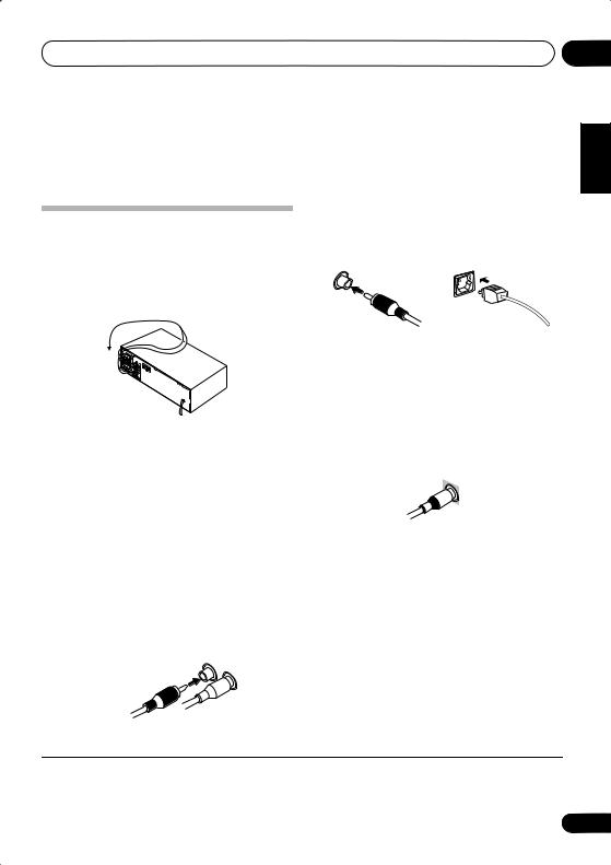
Making cable connections
Make sure not to bend the cables over the top of this unit (as shown in the illustration). If this happens, the magnetic field produced by the transformers in this unit may cause a humming noise from the speakers.
 Important
•Before making or changing any connections, switch off the power and disconnect the power cord from the AC outlet.
Analog audio cables
Use stereo RCA phono cables to connect analog audio components. These cables are typically red and white, and you should connect the red plugs to R (right) terminals and white plugs to L (left) terminals.
Analog audio cables
Right (red)
Left (white)
04
English
Digital audio cables
Commercially available coaxial digital audio |
Deutsch |
||
|
|||
cables or optical cables should be used to |
|
||
connect digital components to this receiver.1 |
|
||
Coaxial digital audio cable |
Optical cable |
Français |
|
|
|||
Video cables |
|
Italiano |
|
Standard RCA video cables |
|||
|
|||
These cables are the most common type of |
|
||
video connection and should be used to |
|
||
connect to the composite video terminals. They |
|
||
have yellow plugs to distinguish them from |
Nederlands |
||
cables for audio. |
|
||
|
|
||
Standard RCA video cable |
|
||
|
|
Español |
|
 Note
Note
1• When connecting optical cables, be careful when inserting the plug not to damage the shutter protecting the optical socket.
•When storing optical cable, coil loosely. The cable may be damaged if bent around sharp corners.
•You can also use a standard RCA video cable for coaxial digital connections.
15
En
04 Connecting up
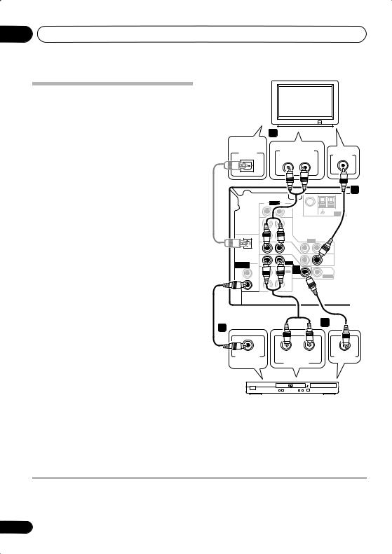
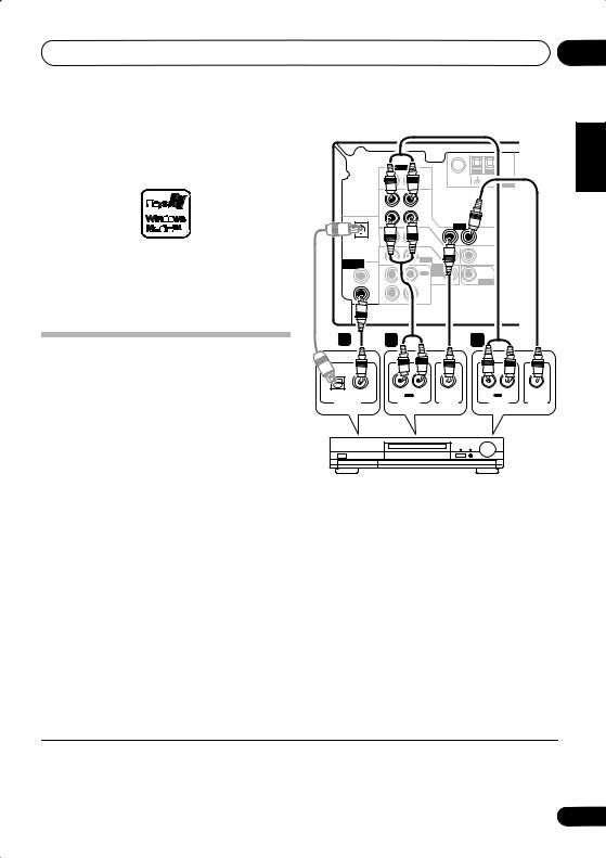
Connecting a DVD player and TV
This page shows you how to connect your DVD player and TV to the receiver.
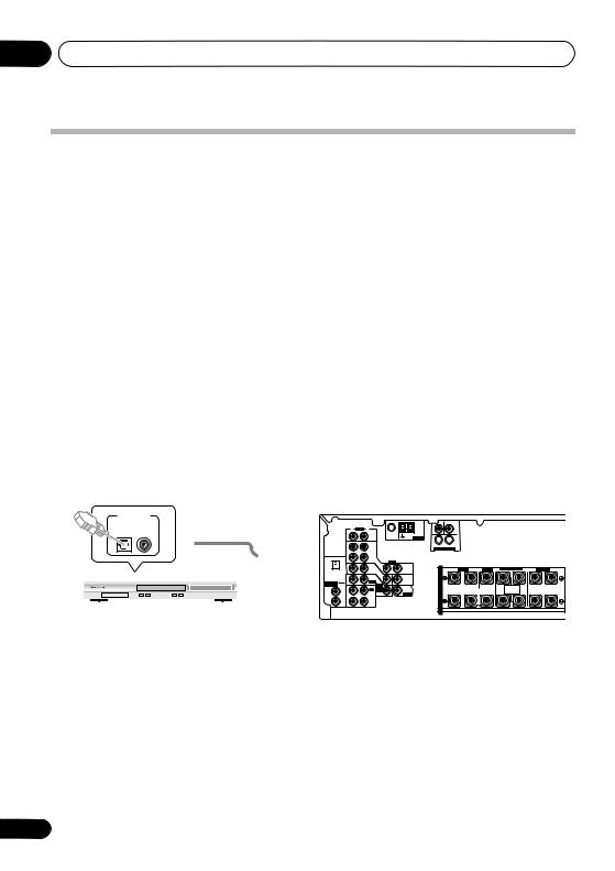
1 Connect a coaxial digital audio output on your DVD player to the DIGITAL COAX 1 (DVD/LD) input on this receiver.
Use a coaxial digital audio cable for the connection.1
2 Connect the composite video output and
the stereo analog audio outputs2 on your DVD player to the DVD/LD inputs on this receiver.
Use a standard RCA video cable and a stereo RCA phono cable for the connection.
•If your DVD player has multichannel analog outputs, see Connecting the multichannel analog outputs below for how to connect it.
3Connect the analog audio outputs from your TV to the TV/SAT inputs on this receiver.
This will allow you to play the sound from the TV's built-in tuner. Use a stereo RCA phono cable to do this.
•If your TV has a built-in digital decoder, you can also connect an optical digital audio output from your TV to the DIGITAL OPT 1 (TV/SAT) input on this receiver. Use an optical cable for the connection.
4Connect the MONITOR OUT video jack on this receiver to a video input on your TV.
Use a standard RCA video cable to connect to the composite video jack.
DIGITAL |
4 |
|
TV |
|
|
|
|
||
AUDIO OUT |
ANALOG AUDIO OUT |
|
||
OPTICAL |
VIDEO IN |
|||
R |
L |
|||
|
||||
|
|
|||
3
|
|
R |
AUDIO L |
|
|
|
|
|
|
FM UNBAL |
AM |
|
|
IN |
CD |
75 Ω |
LOOP ANTENNA |
|
|
OUT |
DVR/ |
|
|
|
|
|
VCR |
|
|
|
OPT |
IN |
|
VIDEO |
|
|
1 |
|
TV / |
IN |
OUT |
|
|
|
|
||
(TV/SAT) |
|
SAT |
|
||
IN |
|
|
|||
|
|
|
|
|
|
|
|
|
DVD |
IN |
|
|
|
|
|
MONITOR |
|
|
|
|
/LD |
|
|
|
|
|
|
OUT |
|
ASSIGNABLE |
|
IN |
FRONT |
|
|
COAX |
D V D |
|
|||
DIGITAL IN |
|
|
|
||
|
2 |
|
REC |
5.1CH |
SUB |
|
(CD) |
|
INPUT |
WOOFER |
|
|
COAX |
OUT |
CD-R |
IN |
PREOUT |
|
|
/ TAPE |
|
|
|
|
1 |
|
/ MD |
|
|
|
|
|
|
|
|
|
(DVD |
IN |
PLAY |
|
|
|
/LD) |
|
|
|
|
This receiver*
2
1
COAXIAL |
R AUDIO L |
VIDEO OUT |
DIGITAL OUT |
ANALOG OUT |
|
DVD player
* The illustration shows the VSX-515, but connections for the VSX-415 are the same.
 Note
Note
1If your DVD player only has an optical digital output, you can connect it to the optical input on this receiver using an optical cable. When you set up the receiver you'll need to tell the receiver which input you connected the player to (for the VSX-415 see
Digital input settings on page 43 and for the VSX-515 see The Input Assign menu on page 51).
2This connection will allow you to make analog recordings from your DVD player.
16
En
Connecting up |
04 |
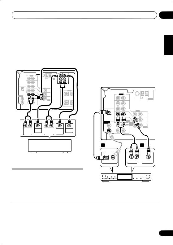
Connecting the multichannel analog outputs
For DVD Audio and SACD playback, your DVD player may have 5.1 channel analog outputs.In this case, you can connect them to the multi-
channel inputs of the receiver as shown below.1
This receiver*
|
|
|
|
|
|
CEN- |
SUB |
|
|
|
|
|
|
|
TER |
WOOFER |
|
|
|
R |
AUDIO L |
|
|
|
|
|
|
|
|
|
FM UNBAL |
AM |
|
|
|
|
|
IN |
CD |
75 Ω |
LOOP ANTENNA |
R |
L |
|
|
|
|
|
|
|
SURROUND |
|
|
|
|
OUT |
DVR/ |
|
|
DVD 5.1CH INPUT |
|
|
|
|
|
|
|
|
|
||
|
|
|
VCR |
|
|
|
|
|
|
OPT |
IN |
|
VIDEO |
|
|
|
|
|
1 |
|
TV / |
IN |
OUT |
|
R FRONT L |
CENT |
|
|
|
|
S |
||||
(TV/SAT) |
IN |
SAT |
|
|
||||
|
|
|
DVD |
IN |
|
P |
|
|
|
|
|
|
MONITOR |
|
|
||
|
|
|
/LD |
|
E |
|
|
|
ASSIGNABLE |
|
IN |
FRONT |
|
OUT |
|
|
|
DIGITAL IN |
COAX |
|
|
D V D |
|
A |
|
|
|
2 |
|
|
5.1CH |
SUB |
|
|
|
|
(CD) |
|
REC |
INPUT |
WOOFER |
K |
|
|
|
|
OUT |
CD-R |
IN |
PREOUT |
|
|
|
|
COAX |
/TAPE |
|
E |
|
|
||
|
1 |
|
/MD |
|
|
|
|
|
|
|
|
|
|
R |
|
|
|
|
(DVD |
IN |
PLAY |
|
|
|
|
|
|
/LD) |
|
|
S |
|
|
||
|
|
|
|
|
|
|
|
|
R |
L |
CENTER |
R |
L |
SUB |
VIDEO |
FRONT |
OUTPUT |
SURROUND |
WOOFER |
OUTPUT |
||
OUTPUT |
|
OUTPUT |
OUTPUT |
|
||
DVD/multi-channel decoder with multi-channel analog output jacks
* The illustration shows the VSX-515, but connections for the VSX-415 are the same.
Connecting a satellite receiver or other digital set-top box
Satellite and cable receivers, and terrestrial digital TV tuners are all examples of so-called `set-top boxes'.
1 Connect a set of audio/video outputs on the set-top box component to the TV/SAT
AUDIO and VIDEO inputs on this receiver.2
Use a stereo RCA phono cable for the audio connection and a standard RCA video cable for the video connection.
2 Connect an optical digital audio output from your set-top box component to the DIGITAL OPT 1 (TV/SAT) input on this receiver.
Use an optical cable for the connection.3
This receiver*
|
|
R |
AUDIO L |
|
|
|
|
|
|
FM UNBAL |
AM |
|
|
IN |
CD |
75 Ω |
LOOP ANTENNA |
|
|
OUT |
DVR/ |
|
|
|
|
|
VCR |
|
|
|
OPT |
IN |
|
VIDEO |
|
|
|
|
|
||
|
1 |
|
TV / |
IN |
OUT |
|
|
|
|
||
(TV/SAT) |
|
SAT |
|
||
IN |
|
|
|||
|
|
|
|
|
|
|
|
|
DVD |
IN |
|
|
|
|
|
MONITOR |
|
|
|
|
/LD |
|
|
ASSIGNABLE |
|
IN |
FRONT |
|
OUT |
COAX |
D V D |
|
|||
DIGITAL IN |
|
|
|
||
|
2 |
|
REC |
5.1CH |
SUB |
|
(CD) |
|
INPUT |
WOOFER |
|
|
COAX |
OUT |
CD-R |
IN |
PREOUT |
|
|
/ TAPE |
|
|
|
|
1 |
|
/ MD |
|
|
|
|
|
|
|
|
|
(DVD |
IN |
PLAY |
|
|
|
/LD) |
|
|
||
|
|
|
|
|
|
2 |
|
|
1 |
DIGITAL OUT |
|
|
|
OPTICAL |
COAXIAL |
R AUDIO L |
VIDEO |
|
|
|
AV OUT |
STB
* The illustration shows the VSX-515, but connections for the VSX-415 are the same.
Español Nederlands Italiano Français Deutsch English
 Note
Note
1The multichannel input can only be used when DVD 5.1 ch is selected (see page 39).
2If you've already connected your TV to the TV/SAT inputs, simply choose another input. However, you'll need to tell the receiver which input you connected the set-top box to (for the VSX-415 see Digital input settings on page 43 and for the VSX-515 see The Input Assign menu on page 51).
3If your set-top box doesn’t have a digital audio output, omit this step. If it only has a coaxial digital output, you can connect it to one of the coaxial inputs on this receiver, but you'll need to tell the receiver which input you connected the set-top box to (for the VSX-415 see Digital input settings on page 43 and for the VSX-515 see The Input Assign menu on page 51).
17
En
04 Connecting up
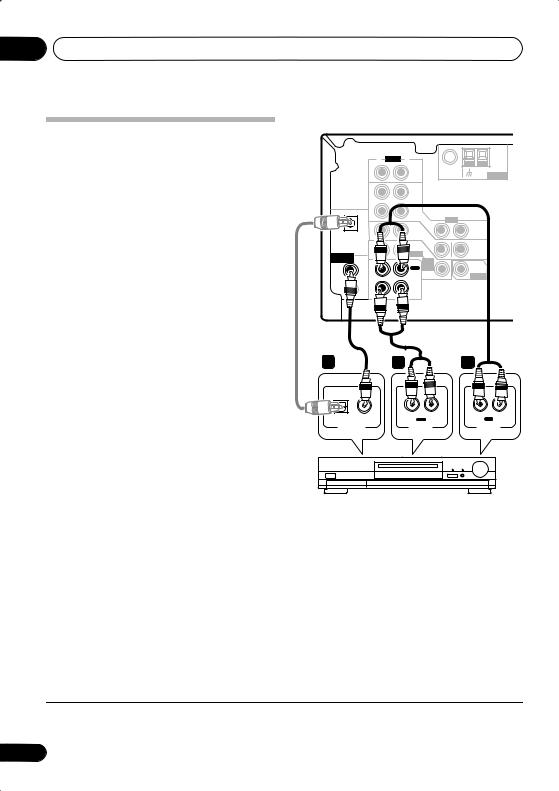
Connecting other audio components
The number and kind of connections depends
on the kind of component you’re connecting.1 Follow the steps below to connect a CD-R, MD, DAT, tape recorder or other audio component.
1If your component has a digital output, connect this to a digital input on the receiver as shown.
The example shows a coaxial connection to the CD digital input jack using a coaxial digital audio cable.
2If necessary, connect the analog audio outputs of the component to a set of spare audio inputs on this receiver.
You’ll need to make this connection for components without a digital output, or if you want to record from a digital component. Use a stereo RCA phono cable as shown.
3If you're connecting a recorder, connect the analog audio outputs (REC) to the analog audio inputs on the recorder.
The example shows an analog connection to the CD-R/TAPE/MD analog output jack using a stereo RCA phono cable.
This receiver*
|
|
R |
AUDIO L |
|
|
|
|
|
|
FM UNBAL |
AM |
|
|
IN |
CD |
75 Ω |
LOOP ANTENNA |
|
|
OUT |
DVR/ |
|
|
|
|
|
VCR |
|
|
|
OPT |
IN |
|
VIDEO |
|
|
|
|
|
||
|
1 |
|
TV / |
IN |
OUT |
|
|
|
|
||
(TV/SAT) |
|
SAT |
|
||
IN |
|
|
|||
|
|
|
|
|
|
|
|
|
DVD |
IN |
|
|
|
|
|
MONITOR |
|
|
|
|
/LD |
|
|
|
|
|
|
OUT |
|
ASSIGNABLE |
|
IN |
FRONT |
|
|
COAX |
D V D |
|
|||
DIGITAL IN |
|
|
|
||
|
2 |
|
REC |
5.1CH |
SUB |
|
(CD) |
|
INPUT |
WOOFER |
|
|
|
CD-R |
IN |
PREOUT |
|
|
|
OUT |
|||
|
COAX |
/ TAPE |
|
|
|
|
|
/ MD |
|
|
|
|
1 |
|
|
|
|
|
|
|
|
|
|
|
(DVD |
IN |
PLAY |
|
|
|
/LD) |
|
|
|
|
1 |
|
2 |
3 |
|
OPTICAL |
COAXIAL |
R OUT L |
R IN |
L |
|
|
PLAY |
REC |
|
DIGITAL OUT |
AUDIO OUT |
AUDIO IN |
|
|
CD-R, MD, DAT, Tape recorder, etc.
* The illustration shows the VSX-515, but connections for the VSX-415 are the same.
About the WMA9 Pro decoder
VSX-515 model only
This unit has an on-board Windows Media® Audio 9 Professional (WMA9 Pro) decoder, so it is possible to playback WMA9 Pro-encoded audio using a coaxial or optical digital connection when connected to a WMA9 Pro-
 Note
Note
1 Note that you must connect digital components to analog audio jacks if you want to record to/from digital components (like an MD) to/from analog components.
18
En
Connecting up |
04 |
compatible player. However, the connected PC, DVD player, set-top box, etc. must be able to output WMA9 Pro format audio signals through a coaxial or optical digital output.
Microsoft, Windows Media®, and the Windows logo are trademarks, or registered trademarks of Microsoft Corporation in the United States and/ or other countries.
Connecting other video components
This receiver has audio/video inputs and outputs suitable for connecting analog or digital video recorders, including VCRs, DVDrecorders and HDD recorders.
1Connect a set of audio/video outputs on the recorder to the DVR/VCR AUDIO and VIDEO inputs on this receiver.
Use a stereo RCA phono cable for the audio connection and a standard RCA video or S- video cable for the video connection.
2Connect a set of audio/video inputs on the recorder to the DVR/VCR AUDIO and VIDEO outputs on this receiver.
Use a stereo RCA phono cable for the audio connection and a standard RCA video or S- video cable for the video connection.
3If your video component has a digital audio output, connect it to a digital input on this receiver.
The example shows a recorder connected to
the DIGITAL COAX 1 (DVD/LD) input.1
This receiver*
|
|
|
R |
AUDIO |
L |
|
|
|
|
|
|
|
|
|
|
FM UNBAL |
AM |
|
|
|
|
|
IN |
|
CD |
75 Ω |
LOOP |
ANTENNA |
|
|
|
|
|
|
|
|
|
||
|
|
|
OUT |
|
DVR/ |
|
|
|
|
|
|
|
|
|
VCR |
|
|
|
|
|
|
OPT |
IN |
|
|
VIDEO |
|
|
|
|
|
1 |
|
|
TV / |
IN |
OUT |
|
|
|
|
|
|
|
|
|
|
||
|
(TV/SAT) |
|
|
SAT |
|
|
|
||
|
IN |
|
|
|
|
|
|||
|
|
|
|
|
|
|
|
|
|
|
|
|
|
|
DVD |
IN |
|
|
|
|
|
|
|
|
|
MONITOR |
|
|
|
|
|
|
|
|
/LD |
|
|
|
|
ASSIGNABLE |
|
IN |
|
FRONT |
|
OUT |
|
|
|
COAX |
|
D V D |
|
|
|
||||
DIGITAL IN |
|
|
|
|
|
|
|||
|
|
2 |
|
|
REC |
5.1CH |
SUB |
|
|
|
|
(CD) |
|
|
INPUT |
WOOFER |
|
|
|
|
|
COAX |
OUT |
|
CD-R |
IN |
PREOUT |
|
|
|
|
|
|
/ TAPE |
|
|
|
|
|
|
|
1 |
|
|
/ MD |
|
|
|
|
|
|
|
|
|
|
|
|
|
|
|
|
(DVD |
IN |
|
PLAY |
|
|
|
|
|
|
/LD) |
|
|
|
|
|
|
|
3 |
|
|
1 |
|
|
|
2 |
|
|
OPTICAL |
COAXIAL |
|
|
R OUT |
L |
|
R |
IN L |
|
|
|
|
|
PLAY |
|
|
|
REC |
|
DIGITAL OUT |
|
|
AUDIO OUT |
VIDEO OUT |
AUDIO IN |
VIDEO IN |
|||
VCR, DVR, LD player, etc.
* The illustration shows the VSX-515, but connections for the VSX-415 are the same.
Español Nederlands Italiano Français Deutsch English
 Note
Note
1 If your video component doesn’t have a digital audio output, omit this step. If it only has an optical digital output, you can connect it to the optical input on this receiver using an optical cable. When you set up the receiver you'll need to tell the receiver which input you connected the component to (for the VSX-415 see Digital input settings on page 43 and for the VSX-515 see The Input Assign menu on page 51).
19
En
04 Connecting up
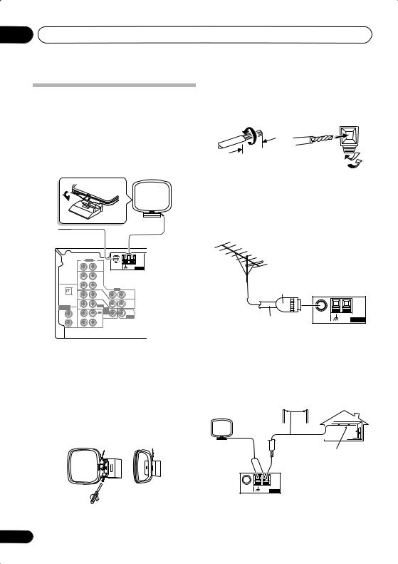
Connecting antennas
Connect the AM loop antenna and the FM wire antenna as shown below. To improve reception and sound quality, connect external antennas (see Using external antennas below). Always make sure that the receiver is switched off and unplugged from the wall outlet before making or changing any connections.
|
|
|
|
|
|
AM loop |
||
|
|
|
|
|
|
antenna |
||
FM wire |
|
|
|
|
|
|
||
antenna |
|
|
|
|
|
|
||
|
|
|
|
|
|
|
CEN- |
SUB |
|
|
|
|
|
|
|
TER |
WOOFER |
|
|
R AUDIO |
L |
|
|
|
|
|
|
|
|
|
FM UNBAL |
AM |
|
|
|
|
|
IN |
CD |
75 Ω |
LOOP ANTENNA |
R |
L |
|
|
|
|
|
|
|
|
SURROUND |
|
|
|
OUT |
DVR/ |
|
|
|
DVD 5.1CH INPUT |
|
|
|
|
|
|
|
|
||
|
|
|
VCR |
|
|
|
|
|
|
OPT |
IN |
|
VIDEO |
|
|
|
|
|
1 |
|
TV / |
IN |
OUT |
|
|
R F |
|
|
|
|
|
S |
|||
(TV/SAT) |
IN |
SAT |
|
|
|
|||
|
|
|
DVD |
IN |
|
|
P |
|
|
|
|
|
MONITOR |
|
|
||
|
|
|
/LD |
|
|
E |
|
|
ASSIGNABLE |
|
IN |
FRONT |
|
OUT |
|
|
|
COAX |
D V D |
|
|
|
||||
DIGITAL IN |
|
|
|
|
A |
|
||
|
2 |
|
|
5.1CH |
SUB |
|
|
|
|
(CD) |
|
REC |
INPUT |
WOOFER |
|
K |
|
|
|
OUT |
CD-R |
IN |
PREOUT |
|
|
|
|
COAX |
/TAPE |
|
|
E |
|
||
|
1 |
|
/MD |
|
|
|
|
|
|
|
|
|
|
|
R |
|
|
|
(DVD |
IN |
PLAY |
|
|
|
|
|
|
/LD) |
|
|
|
|
|
||
S
FM wire antenna
Connect the FM wire antenna and fully extend vertically along a window frame or another suitable place that gives good reception.
AM loop antenna
Assemble the antenna and connect to the receiver. Attach (if necessary) and face in the direction that gives the best reception.
20
Antenna snap connectors
Twist the exposed wire strands together and insert into the hole, then snap the connector shut.
10mm
Using external antennas
To improve FM reception
Use a PAL connector to connect an external FM antenna.
One-touch
PAL connector
75Ω coaxial cable |
FM UNBAL |
AM |
|
75 Ω |
LOOP ANTENNA |
||
|
To improve AM reception
Connect a 5–6 meter length of vinyl-coated wire to the AM antenna terminal without disconnecting the supplied AM loop antenna.
For the best possible reception, suspend horizontally outdoors.
Outdoor antenna
5–6m
Indoor antenna (vinyl-coated wire)
FM UNBAL |
AM |
75 Ω |
LOOP ANTENNA |
En
Connecting up
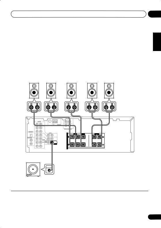
Connecting the speakers (VSX-415)
A complete setup of six speakers (including the subwoofer) is shown below, but everyone’s home setup will vary. Simply connect the speakers you have in the manner shown below. The receiver will work with just two stereo speakers (the front speakers in the diagram) but using at least three speakers is recommended, and a complete setup is best. If you’re not using a subwoofer, change the front speaker setting (see Speaker setting on page 41) to large.
Make sure you connect the speaker on the right to the right terminal and the speaker on the left to the left terminal. Also make sure the positive and negative (+/–) terminals on the receiver match those on the speakers. You can use speakers with a nominal impedance between 6–16Ω (please see Switching the speaker impedance on page 61 if you plan to use speakers with an impedance of less than 8Ω).
Be sure to complete all connections before connecting this unit to the AC power source.
Front speakers |
Center speaker |
Surround speakers |
||
L |
R |
C |
LS |
RS |
04
Italiano Français Deutsch English
VSX-415
|
|
|
|
|
|
TERCEN- |
SUB WOOFER |
|
|
|
R |
AUDIO L |
|
|
|
|
|
|
|
|
|
|
FM UNBAL |
AM |
|
|
|
|
|
|
IN |
CD |
75 Ω |
LOOP ANTENNA |
R |
|
L |
|
|
|
|
|
|
|
|
SURROUND |
|
|
|
|
OUT |
DVR/ |
|
|
|
DVD 5.1CH INPUT |
|
|
|
|
|
VCR |
|
|
|
|
|
|
|
DIGITAL IN |
IN |
|
|
|
|
|
|
|
|
OPT |
|
VIDEO |
|
|
|
|
|
|
|
|
|
|
|
S |
R FRONT L |
CENTER |
R SURROUND L |
||
1 |
|
TV / |
IN |
OUT |
|
||||
(TV / |
IN |
SAT |
|
|
|
P |
|
|
|
SAT) |
|
IN |
|
|
|
|
|
||
ASSIGNABLE COAX |
|
DVD |
|
|
E |
|
|
|
|
|
|
MONITOR |
|
|
|
|
|||
2 |
|
/LD |
|
OUT |
|
A |
|
|
|
(CD) |
IN |
FRONT |
D V D |
|
|
|
|
||
COAX |
|
REC |
5.1CH |
SUB |
|
K |
|
|
|
1 |
|
INPUT |
WOOFER |
|
E |
|
|
|
|
OUT |
CD-R |
IN |
PREOUT |
|
|
|
|
||
(DVD |
/TAPE |
|
|
|
R |
|
|
|
|
/LD) |
|
/MD |
|
|
|
|
|
|
|
|
IN |
PLAY |
|
|
|
S |
|
|
|
Powered subwoofer |
1 |
2 |
3 |
|
SW |
||||
|
|
|
||
INPUT |
|
10mm |
|
|
|
|
|
Español Nederlands
1Twist exposed wire strands together.
2Loosen terminal and insert exposed wire.
3Tighten terminal.
21
En
04 Connecting up
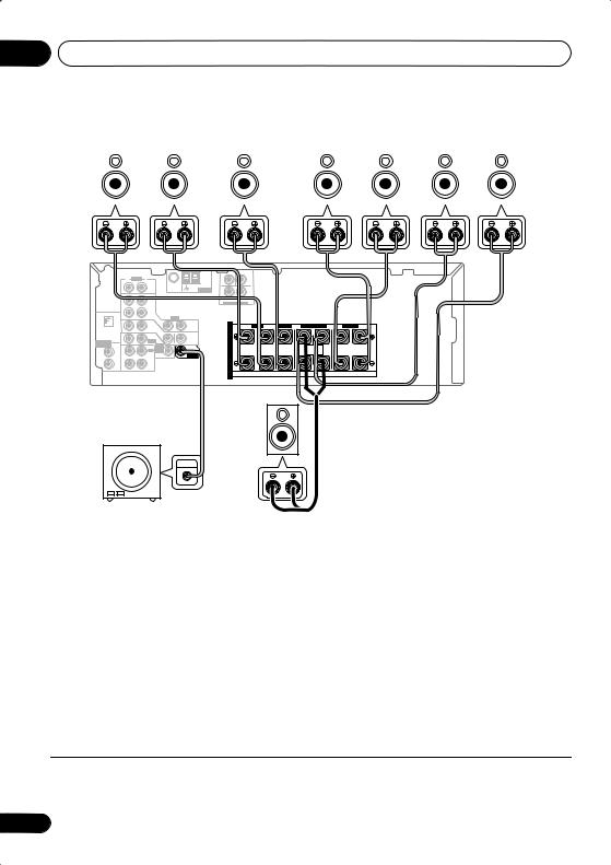
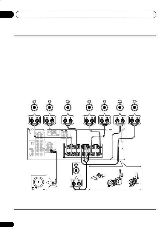
Connecting the speakers (VSX-515)
A complete setup of eight speakers (including the subwoofer) is shown below, but everyone’s home setup will vary. Simply connect the speakers you have in the manner shown below. The receiver will work with just two stereo speakers (the front speakers in the diagram) but using at least three speakers is recommended, and a complete setup is best for surround sound. If you’re not using a subwoofer, change the front speaker setting (see Speaker setting on page 48) to LARGE.
Make sure you connect the speaker on the right to the right terminal and the speaker on the left to the left terminal. Also make sure the positive and negative (+/–) terminals on the receiver match
those on the speakers.1 You can use speakers with a nominal impedance between 6–16Ω (please see Switching the speaker impedance on page 61 if you plan to use speakers with an impedance of less than 8Ω).
Be sure to complete all connections before connecting this unit to the AC power source.
Front speakers |
Center speaker |
Surround speakers |
Surround back speakers |
|||||||||||
L |
|
R |
|
C |
LS |
|
RS |
|
SBL |
SBR |
||||
|
|
|
|
|
|
|
|
|
|
|
|
|
|
|
|
|
|
|
|
|
|
CEN- |
SUB |
|
|
|
|
|
|
|
|
|
|
TER |
WOOFER |
|
|
|
|
|
R |
AUDIO L |
|
|
|
|
|
|
|
|
|
|
|
|
FM UNBAL |
AM |
|
|
|
|
|
|
|
|
IN |
CD |
75 Ω |
LOOP |
ANTENNA |
R |
L |
|
|
|
|
|
|
|
|
|
|
|
||||
|
|
|
|
|
|
|
SURROUND |
|
|
|
|
|
|
OUT |
DVR/ |
|
|
|
DVD 5.1CH INPUT |
|
|
|
|
|
|
|
|
|
|
|
|
|
|
||
|
|
|
VCR |
|
|
|
|
|
|
|
|
|
OPT |
IN |
|
VIDEO |
|
|
|
|
|
|
|
|
1 |
|
TV / |
IN |
|
|
|
R FRONT L |
CENTER |
R SURROUND BACK L |
R SURROUND L |
|
|
|
|
OUT |
|
S |
|||||
(TV/SAT) |
IN |
SAT |
|
|
|
||||||
|
|
|
DVD |
IN |
|
|
P |
|
|
|
|
|
|
|
/LD |
|
MONITOR |
|
E |
|
|
|
|
ASSIGNABLE |
|
IN |
FRONT |
|
OUT |
|
|
|
|
|
|
COAX |
D V D |
|
|
|
|
|
|
||||
DIGITAL IN |
|
|
|
|
A |
|
|
SINGLE |
|
||
|
2 |
|
REC |
5.1CH |
SUB |
|
|
|
|
||
|
(CD) |
|
INPUT |
WOOFER |
|
K |
|
|
SEEINSTRUCTION |
|
|
|
|
CD-R |
IN |
|
|
|
MANUAL |
|
|||
|
COAX |
OUT |
PREOUT |
|
|
|
|
|
|||
|
|
/TAPE |
|
|
|
E |
|
|
|
|
|
|
1 |
|
/MD |
|
|
|
|
|
|
|
|
|
|
|
|
|
|
R |
|
|
|
|
|
|
(DVD |
IN |
PLAY |
|
|
|
|
|
|
|
|
|
/LD) |
|
|
|
|
|
|
|
|||
|
|
|
|
|
|
|
S |
|
|
|
|
VSX-515 |
Single |
|
|
|
|
Powered subwoofer |
surround |
|
|
|
|
back |
1 |
2 |
3 |
||
SW |
speaker |
||||
|
|
|
|||
INPUT |
|
|
10mm |
|
|
|
|
|
|
1Twist exposed wire strands together.
2Loosen terminal and insert exposed wire.
3Tighten terminal.
 Note
Note
1 If you are using only one surround back speaker, connect the positive wire to the right channel (+) terminal, and the negative wire to the left channel (–) terminal (see illustration).
22
En
Connecting up |
04 |
Speaker terminals
Make sure that all the bare speaker wire is twisted together and inserted fully into the speaker terminal. If any of the bare speaker wire is touching the back panel when you switch the unit on, the power may cut off as a safety measure. Use good quality speaker wire to connect the speakers to the receiver.
 Caution
•These speaker terminals are hazardous when live. To prevent the risk of electric shock when connecting or disconnecting the speaker cables, disconnect the power cord.
Hints on speaker placement
Speakers are usually designed with a particular placement in mind. Some are designed to be floorstanding, while others should be placed on stands to sound their best. Some should be placed near a wall; others should be placed away from walls. We have provided a few tips on getting the best sound from your speakers (following), but you should also follow the guidelines on placement that the speaker manufacturer provided with your particular speakers to get the most out of them.
•Place the front left and right speakers at equal distances from the TV.
•When placing speakers near the TV, we recommend using magnetically shielded speakers to prevent possible interference, such as discoloration of the picture when the TV is switched on. If you do not have magnetically shielded speakers and notice discoloration of the TV picture, move the speakers farther away from the TV.
•Place the center speaker above or below the TV so that the sound of the center channel is localized at the TV screen.
•If possible, place the surround speakers slightly above ear level.
•Try not to place the surround speakers further away from the listening position than the front and center speakers. Doing so can weaken the surround sound effect.
•To achieve the best possible surround sound, install your speakers as shown below. Be sure all speakers are installed securely to prevent accidents and improve sound quality.
 Caution
•If you choose to install the center speaker on top of the TV, be sure to secure it with putty, or by other suitable means, to reduce the risk of damage or injury resulting from the speaker falling from the TV in the event of external shocks such as earthquakes.
•Make sure no exposed speaker wire is touching the rear panel, this may cause the receiver to turn off automatically.
Speaker placement diagrams
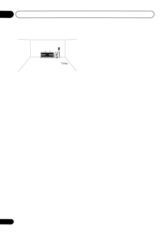
The following illustrations show 6.1 and 7.1 channel speaker setups.1
3-D view of 6.1 channel speaker setup
 Note
Note
1 VSX-415 model only – Follow the speaker placement diagrams, disregarding the surround back speakers.
Español Nederlands Italiano Français Deutsch English
23
En
04 Connecting up
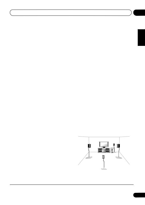
3-D view of 7.1 channel speaker setup
Overhead view of speaker setup
Front |
|
Front |
left |
Center |
right |
|
|
Subwoofer |
Surround |
|
Surround |
left |
|
right |
Listening position |
||
Surround back left |
|
Surround back right |
Single surround back speaker
Extra Power mode speaker setup
VSX-415 only – see Using the Advanced surround effects on page 32 to switch on the Extra Power mode (EX POWER).
Front left |
Center |
Front right |
|
Subwoofer |
|
Surround |
|
Surround |
left |
|
right |
Listening position
24
En
Controls and displays
Chapter 5:
Controls and displays
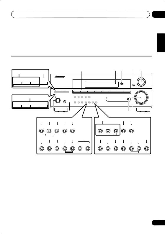
Front panel
1 |
2 |
3 |
4 |
5 |
10 |
11 |
|
|
|
|
|
|
|
|
|
|
AUDIO/VIDEO MULTI-CHANNEL RECEIVER |
|
ADVANCED |
ST/DIRECT |
SIGNAL |
|
|
|
|
|
|
MULTI JOG |
STANDARD |
|
|
|
|
|
|
|
|||
SURR |
/AUTO SURR |
SELECT |
|
|
|
|
|
|
|
|
|
|
|
|
|
|
|
|
|
|
ENTER |
LISTENING MODE |
|
|
|
|
|
|
|
|
||
VSX-515 model |
DVD/LD |
DVD 5.1 |
TV/SAT |
DVR/VCR |
CD |
CD-R/TAPE/MD |
FM |
MASTER |
||
|
|
|
AM |
|||||||
|
|
|
|
|
|
|
|
|
|
VOLUME |
18 |
MCACC |
SETUP MIC |
|
|
STANDBY/ON |
|
|
|
|
|
|
PHONES |
|
– |
STATION |
+ |
– |
TUNING |
+ |
DOWN |
UP |
VSX-415 model |
6 |
|
7 |
|
|
|
|
8 |
9 |
|
|
|
|
|
|
|
|
|
|
|
|||||
12 |
13 |
14 |
15 |
16 |
|
10 |
|
|
11 |
23 |
|
|
EON |
PTY |
SPEAKER |
EXTENDED |
ACOUSTIC |
|
STANDARD |
ADVANCED |
STEREO/ |
SIGNAL |
VSB |
|
|
MODE |
SEARCH |
IMPEDANCE |
MODE |
EQ |
|
SURROUND |
DIRECT |
SELECT |
MODE |
|
|
|
|
MULTI JOG |
|
|
|
|
LISTENING MODE |
|
|
|
|
||
17 |
18 |
19 |
20 |
21 |
22 |
14 |
24 |
12 |
13 |
19 |
20 |
21 |
|
TUNING |
TUNER |
|
QUICK |
SYSTEM |
SPEAKER |
|
EON |
PTY |
TUNER |
|
QUICK |
CLASS |
/STATION |
EDIT |
TONE |
SETUP |
SETUP RETURN |
IMPEDANCE |
MUTE |
MODE |
SEARCH |
EDIT |
TONE |
SETUP |
|
|
|
MULTI JOG |
|
|
|
|
|
MULTI JOG |
|
||
VSX-515 model
1 Input select buttons
Press to select an input source.
2Character display
See Display on page 27.
3MCACC indicator
Lights when Acoustic Calibration EQ (page 34) is on (Acoustic Calibration EQ is automatically set to ALL CH ADJUST after the Auto MCACC Setup (page 13) or EQ Auto Setup (page 46) is complete).
VSX-415 model
5 MULTI JOG dial
The MULTI JOG dial performs a number of tasks. Use it to select options after pressing the designated MULTI JOG buttons.
6 STANDBY/ON
Switches the receiver between on and standby.
7 PHONES jack
Use to connect headphones. When the headphones are connected, there is no sound output from the speakers.
4 ENTER
05
Español Nederlands Italiano Français Deutsch English
25
En

05 Controls and displays
8 MCACC SETUP MIC jack
Use to connect the supplied microphone (page 13).
9MASTER VOLUME
10LISTENING MODE buttons
STANDARD
Press for Standard decoding and to switch between the various Pro Logic II and Neo:6 options (page 31).
ADVANCED SURROUND
Use to switch between the various surround modes (page 32).
ST/DIRECT/AUTO SURR – VSX-515 model STEREO/DIRECT – VSX-415 model Switches between direct and stereo playback. Direct playback bypasses the tone controls and channel levels for the most accurate reproduction of a source (page 34).
VSX-515 model only – Selects the Auto Surround mode (page 31).
11SIGNAL SELECT
Use to select an input signal (page 35).
12 EON MODE
Use to search for programs that are broadcasting traffic or news information (page 56).
13 PTY SEARCH
Use this button to search for RDS program types (page 55).
14 SPEAKER IMPEDANCE
Use to change the impedance setting (page 61)
15 EXTENDED MODE
VSX-515 model only
Selects a surround back channel option (page 36) or (when the surround back speakers are not available) the Virtual Surround Back (VSB) mode (page 37).
26
16 ACOUSTIC EQ
Press to select an Acoustic Calibration EQ setting (page 34).
17 CLASS
VSX-515 model only
Switches between the three banks (classes) of station presets (page 53).
18 TUNING / STATION buttons
Selects the frequency (page 53) and station presets (page 54) when using the tuner.
19 TUNER EDIT
Press to memorize and name a station for recall (page 53).
20 TONE
Press this button to access the bass and treble controls, which you can then adjust with the MULTI JOG dial (page 38).
21 QUICK SETUP
See Using the Quick Setup on page 11.
22 System Setup menu controls
VSX-515 model only
SYSTEM SETUP
Use with the MULTI JOG dial to access the System Setup menu (page 44).
RETURN
Press to confirm and exit the current menu screen.
23 VSB MODE
VSX-415 model only
Selects the Virtual Surround Back (VSB) mode (page 37).
24 MUTE
VSX-415 model only
Mutes the sound (or restores the sound if it has been muted).
En

Controls and displays
Display
VSX-515 model:
1 |
2 |
13 14
3 |
4 |
5 |
6 |
|
7 |
8 |
9 |
10 |
11 |
12 |
|
|
|
|
|
|
|
|
|
|
EON |
[ L ] |
6 |
|
|
|
|
|
|
|
|
|
RDS |
[ C ] |
|
|
|
|
|
|
|
|
|
SP AB [ R ] |
|
||
|
|
|
|
|
|
|
|
|
|
[Rs] |
0 |
|
|
|
|
|
|
|
|
|
|
[SBR] |
|
|
|
|
|
|
|
|
|
|
|
[SBL] |
|
|
|
|
|
|
|
|
|
|
|
[Ls] |
6 |
|
|
|
|
|
|
|
|
|
|
|
|
|
|
|
|
|
|
|
|
|
|
|
40 125 250 4K13K |
|
15 |
|
16 |
17 |
18 |
19 |
|
20 |
21 |
|
22 |
VSX-415 model:
1 |
2 |
3 |
4 |
5 |
6 |
9 |
8 |
11 |
12 |
EON
RDS
13 |
15 |
17 |
19 |
|
10 |
21 |
|
1 SIGNAL SELECT indicators |
|
2 |
|
|
|
|
|
|
|
|
|
|
|
||
Lights to indicate the type of input signal: |
|
|
|
|
|
|
|
|
When the STANDARD mode of the receiver is |
||||||
• AUTO – Lights when AUTO signal select is |
|
||||||
|
on, this lights to indicate decoding of a DTS |
||||||
on. |
|
multichannel signal. |
|
||||
• SB – Depending on the source, this lights |
|
3 |
2 DIGITAL |
|
|
||
when a signal with surround back channel |
|
|
|
||||
|
When the STANDARD mode of the receiver is |
||||||
encoding is detected. |
|
||||||
|
on, this lights to indicate decoding of a Dolby |
||||||
• DIGITAL – Lights when a digital audio |
|
||||||
|
Digital multichannel signal. |
|
|||||
signal is detected. |
|
4 2 PRO LOGIC II x |
|
||||
• 2 DIGITAL – Lights when a Dolby Digital |
|
|
|||||
|
When the (STANDARD) Pro Logic II mode of |
||||||
encoded signal is detected. |
|
||||||
|
the receiver is on, 2 PRO LOGIC II lights to |
||||||
• ANALOG – Lights when an analog signal is |
|
||||||
|
indicate Pro Logic II decoding. |
||||||
detected. |
|
|
|
|
|
|
|
DTS – Lights when a source with DTS encoded audio signals is detected.
05
Español Nederlands Italiano Français Deutsch English
27
En

05 Controls and displays
VSX-515 model only – 2 PRO LOGIC II x lights to indicate Pro Logic IIx decoding (see
Listening in surround sound on page 31 for more on this).
5 VIR.SB
Lights during Virtual surround back processing (page 37).
6 DIRECT
Lights when source direct playback is in use. Direct playback bypasses the tone controls and channel levels for the most accurate reproduction of a source.
7AUTO SURR. (VSX-515 model only)
Lights when the Auto Surround feature is switched on (see page 31).
8ATT
Lights when INPUT ATT is used to attenuate (reduce) the level of the analog input signal.
9 SLEEP
Lights when the receiver is in sleep mode (page 39).
10Tuner indicators
• / MONO – Lights when the mono mode is set using the MPX button.
• / STEREO – Lights when a stereo FM broadcast is being received in auto stereo mode.
•
 / TUNED – Lights when a broadcast is being received.
11EON 
EON lights when the EON mode is set, and flashes during reception of an EON
broadcast. The  indicator lights when the current station carries the EON service (page 56).
RDS
Lights when an RDS broadcast is received (page 55).
28
12 Speaker indicator
Shows if the speaker system is on or not. SP A means the speakers are switched on. SP means the headphones are connected.
13Character display
14Neo:6 (VSX-515 model only)
When the (STANDARD) Neo:6 mode of the receiver is on, this lights to indicate Neo:6 processing.
15ADV.SURR. (Advanced Surround)
Lights when one of the Advanced Surround modes has been selected.
16WMA9 Pro (VSX-515 model only)
Lights to indicate decoding of a WMA9 Pro signal.
17MIDNIGHT
Lights during Midnight listening (page 38).
18 D.E. (VSX-515 model only)
Lights when Dialog Enhancement (DIALOG E) is switched on (page 38).
19 LOUDNESS
Lights during Loudness listening (page 38).
20 EX
Lights when a Dolby Digital Surround EX encoded signal is detected.
21 Master volume level
Shows the overall volume level. ---dB indicates the minimum level, and - 0 dB indicates the maximum level.
Depending on your level settings for each channel, the maximum volume can range between –10 dB and –0 dB.
22 MCACC channel EQ indicators (VSX-515 model only)
These indicators show the EQ balance for each channel when checking your Acoustic Calibration EQ settings. See Checking your Acoustic Calibration EQ settings on page 48 for more on this.
En
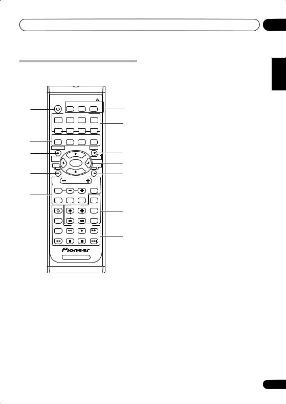
Controls and displays |
05 |
Remote control
Illustration shows the VSX-515 remote control
1 |
RECEIVER SLEEP FL DIMMER INPUT ATT |
6 |
||||
|
INPUT SELECTOR |
|
||||
|
|
|
|
|||
|
DVD/LD DVD 5.1CH |
TV/SAT |
DVR/VCR |
|
||
|
CD |
|
CD-R/ |
FM |
AM |
7 |
|
TAPE/MD |
|
||||
|
|
ADVANCED |
STEREO |
MIDNIGHT/ |
|
|
2 |
STANDARD SURROUND |
LOUDNESS |
|
|||
|
|
|
|
|
|
|
3 |
TOP MENU |
|
|
MENU |
8 |
|
SYSTEM |
|
|
|
|
||
|
|
|
|
RETURN |
|
|
|
SETUP |
|
ENTER |
|
9 |
|
|
DVD |
|
RECEIVER |
|||
|
|
|
|
|||
4 |
|
RECEIVER CONTROL |
|
10 |
||
|
|
|
|
|||
|
|
|
VOLUME |
|
|
|
|
EFFECT/CHSEL |
LEVEL |
MUTE |
|
||
5 |
DIALOGE |
ACOUSTIC |
TUNER |
CLASS |
|
|
|
EQ |
EDIT |
|
|||
|
DVD |
|
TUNER |
MPX |
11 |
|
|
|
TUNING |
STATION DISPLAY |
|||
|
AUDIO |
|
||||
|
SUBTITLE |
|
DVD CONTROL |
|
||
|
|
|
|
|
|
12 |
|
|
RECEIVER |
|
|
||
1 |
RECEIVER |
|
|
|
|
|
Switches the receiver between standby and on.
2Listening mode buttons
STANDARD
Press for Standard decoding and to switch between the various Pro Logic II and Neo:6 options (page 31).
ADVANCED SURROUND
Use to switch between the various surround modes (page 32).
STEREO
Switches between direct and stereo playback. Direct playback bypasses the tone controls and channel levels for the most accurate reproduction of a source (page 34).
VSX-515 model only – Selects the Auto Surround mode(page 31).
MIDNIGHT/LOUDNESS
Switches to Midnight or Loudness listening (page 38).
3TOP MENU
Displays the disc ‘top’ menu of a DVD.
SYSTEM SETUP (VSX-515 model only)
Press to access the System Setup menu (page 44).
TUNER EDIT (VSX-415 model only)
Press to memorize and name a station for recall (page 53).
4DVD
Press to use the DVD controls on the remote.
5RECEIVER CONTROL buttons
VOLUME +/–
Use to set the listening volume.
MUTE
Mutes/unmutes the sound.
VSX-515 model only:
EFFECT/CH SEL
Press repeatedly to select a channel, then use LEVEL +/– to adjust the level (page 50). Also adjusts the level of the Advanced Surround effects (page 32) as well as Dolby Pro Logic IIx Music (page 33) and Neo:6 Music parameters (page 34). You can then use the LEVEL +/– buttons to make these adjustments.
LEVEL +/–
Use to adjust the effect and channel levels, as well as to change Dolby Pro Logic IIx and Neo:6 Music parameter settings.
Español Nederlands Italiano Français Deutsch English
29
En

05 Controls and displays
DIALOG E
Use to make dialog stand out when watching TV or a movie (page 38).
ACOUSTIC EQ
Press to select an Acoustic Calibration EQ setting (page 34).
TUNER EDIT
Press to memorize and name a station for recall (page 53).
VSX-415 model only:
CH SELECT
Selects a speaker when setting up the surround sound of the receiver (page 43).
TEST TONE
Sounds the test tone when setting up the surround sound of the receiver (page 43).
LEVEL +/–
Adjusts the channel levels (page 43).
EFFECT +/–
Adds or subtracts the amount of effect with the advanced surround modes (page 32).
6SLEEP
Use to set the sleep timer (page 39).
FL DIMMER
Dims or brightens the display.
INPUT ATT
Attenuates (lowers) the level of an analog input signal to prevent distortion.
7INPUT SELECTOR buttons
Press to select an input source.
8MENU
Displays the disc menu of DVD-Video discs. It also displays TV menus.
RETURN (VSX-515 model only)
Confirm and exit the current menu screen.
9/ENTER
Use the arrow buttons when setting up your surround sound system (VSX-415 – page 40, VSX-515 – page 44). Also used for DVD menus.
30
10 RECEIVER
Use to switch to the receiver controls on the remote control. Also used when setting up the surround sound for the receiver (VSX-415 – page 40, VSX-515 – page 44).
11 TUNER controls
The TUNING +/– buttons can be used to find radio frequencies (page 53) and the STATION +/– buttons can be used to select preset radio stations (page 54).
CLASS
Switches between the three banks (classes) of station presets (page 53).
MPX
Use to switch between auto stereo and mono reception of FM broadcasts. If the signal is weak then switching to mono will improve the sound quality (page 53).
DISPLAY
Switch the display between station preset name and frequency (see tip on page 54).
12 DVD CONTROL buttons
You can use these buttons to control a Pioneer DVD player connected to your system.
Button What it does
DVD Turns DVD power on/off.
AUDIO Changes the audio language or channel.
SUBTITLE Displays/changes the subtitles on multilingual DVD-Video discs.
Starts/resumes normal playback.
Pauses/unpauses a disc.
Stops playback.
Press to start fast reverse scanning.
Press to start fast forward scanning.
Skips to the start of the current track or chapter, then previous tracks/chapters.
Skips to the next track or chapter.
En
 Loading...