


AUDIO/VIDEO
MULTI-CHANNEL RECEIVER
VSX-D938TX VSX-D908TX VSX-D908TX-G
Operating Instructions

Thank you for buying this Pioneer product.
Please read through these operating instructions so you will know how to operate your model properly. After you have finished reading the instructions, put them away in a safe place for future reference.
In some countries or regions, the shape of the power plug and power outlet may sometimes differ from that shown in the explanatory drawings. However the method of connecting and operating the unit is the same.
WARNING: TO PREVENT FIRE OR SHOCK HAZARD, DO NOT EXPOSE THIS APPLIANCE TO RAIN OR MOISTURE.
THE POWER SWITCH IS SECONDARY CONNECTED AND THEREFORE DOES NOT SEPARATE THE UNIT FROM MAINS POWER IN THE STANDBY POSITION.
If the socket outlets on the associated equipment are not suitable for the plug supplied with the product the plug must be removed and appropriate one fitted.
The cut-off plug must be disposed of as an electrical shock hazard could exist if connected to a socket outlet.
VENTILATION
•When installing this unit, make sure to leave space around the unit for ventilation to improve heat radiation (at least 60 cm at top, 10 cm at rear, and 30 cm at each side). If not enough space is provided between the unit and walls or other equipment, heat will build up inside, interfering with performance or causing malfunctions.
•Do not place on a thick carpet, bed, sofa or fabric having a thick pile. Do not cover with fabric or other covering.
Anything that blocks ventilation will cause internal temperature to rise, which may lead to breakdown or the hazard.
IMPORTANT
The lightning flash with arrowhead symbol, within an equilateral triangle, is intended to alert the user to the presence of uninsulated "dangerous voltage" within the product's enclosure that may be of sufficient magnitude to constitute a risk of electric shock to persons.
CAUTION
RISK OF ELECTRIC SHOCK
DO NOT OPEN
CAUTION:
TO PREVENT THE RISK OF ELECTRIC SHOCK, DO NOT REMOVE COVER (OR BACK). NO USER-SERVICEABLE PARTS INSIDE. REFER SERVICING TO QUALIFIED SERVICE PERSONNEL.
The exclamation point within an equilateral triangle is intended to alert the user to the presence of important operating and maintenance (servicing) instructions in the literature accompanying the appliance.
This equipment has been tested and found to comply with the limits for a Class B digital device, pursuant to Part 15 of the FCC Rules. These limits are designed to provide reasonable protection against harmful interference in a residential installation. This equipment generates, uses, and can radiate radio frequency energy and, if not installed and used in accordance with the instructions, may cause harmful interference to radio communications. However, there is no guarantee that interference will not occur in a particular installation. If this equipment does cause harmful interference to radio or television reception, which can be determined by turning the equipment off and on, the user is encouraged to try to correct the interference by one or more of the following measures:
–Reorient or relocate the receiving antenna.
–Increase the separation between the equipment and receiver.
–Connect the equipment into an outlet on a circuit different from that to which the receiver is connected.
–Consult the dealer or an experienced radio/TV technician for help.
Information to User
Alteration or modifications carried out without appropriate authorization may invalidate the user's right to operate the equipment.
2
CHANNEL STEP SETTING (VSX-D908TX/D908TX-G only)
The unit has been factory preset to the channel allocation value for the area in which it is to be sold. If this value is set incorrectly, the tunes in frequency may be wrong, or sound may be distorted, resulting in an inability to reproduce reception signals at their proper sound quality. For this reason, be sure to confirm that the values are set correctly before first using the unit.
FM 100 kHz, AM 10 kHz:
Set to this position for areas with an FM reception step of 100 kHz and AM 10 kHz.
FM 50 kHz, AM 9 kHz:
Set to this position, for areas with an FM reception step of 50 kHz and AM 9 kHz.
NOTE:
When unsure about the channel allocation for your area, consult your dealer for correct information.
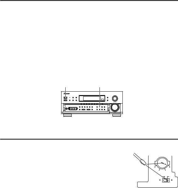
To Change Channel Steps
With the power turned OFF, hold the STANDBY/ON button depressed while pressing the FM/AM function button to turn the power ON.
∙Each time the above operation is performed, the channel tuning step will alternate between FM 100 kHz/AM 10 kHz, and FM 50 kHz/AM 9 kHz.
STANDBY/ON |
FM/AM |
TWO VOLTAGE SELECTOR SWITCHES (VSX-D908TX/ D908TX-G only)
Mains voltages in Saudi Arabia are 127 V and 220 V only. Never use this model with the 110 V setting in Saudi Arabia.
The line voltage selector switches are on the rear panel. Check that they are set properly before plugging the power cord into the household wall socket. If the voltage is not properly set or if you move to an area where the voltage requirements differ, adjust the selector switches as follows.
1.Use a medium-size screwdriver.
2.First, insert the screwdriver in the groove of the voltage selector upper, and adjust so that the tip of the groove points to the voltage value of your area.
3.Next, insert the screwdriver in the groove of the voltage selector lower and adjust until the voltage is the same as at the right.
Medium-size screwdriver
TWO VOLTAGE SELECTORS
220V |
240V |
110V 120V-127V |
|
110V |
220V |
120V-127V |
240V |
3
Features
MPEG (Moving Picture Experts Group) decoder equipped (VSX-D938TX only)
Playback of DVD and other media recorded in MPEG audio is possible.
The MPEG logo is a registered trademark of Royal Philips Electronics.
Decoding of Dolby Digital, Dolby Pro Logic and DTS (Digital Theater Systems) 


DTS is the latest and most widely used digital theater system for cinemas throughout the world. The decoder has been incorporated into this receiver and is able to achieve high sound quality as well as produce dynamic surround sound effects. Also, there is no need to worry about program formats. When playing Dolby Digital, Dolby Pro Logic or Dolby Surround software in the 2(Dolby) Surround and HOME THX CINEMA modes, decoding switches automatically according to the input signal, all you have to do is enjoy!
“DTS” and “DTS Digital Surround” are trademarks of Digital Theater Systems, Inc. Manufactured under licence from Digital Theater Systems, Inc.
Manufactured under license from Dolby Laboratories. “Dolby”, “AC-3”, “Pro Logic”, and double-D symbol are trademarks of Dolby Laboratories. Confidential Unpublished Works. © 1992 - 1997 Dolby Laboratories, Inc. All rights reserved.
Direct Energy MOS Amplifier
This receiver incorporates 5 independent 110 watt (DIN) built in power amplifiers with high-performance Hex power MOS FET output transistors. This construction provides improved linearity and accurate reproduction of each channel for true high fidelity reproduction from even the most demanding Dolby Digital and DTS program sources.
True Home Cinema with THX® Certification
The HOME THX CINEMA surround mode employs special processing to allow you to enjoy movie soundtracks with the same level of power and realism you experience in well designed movie theaters. You can enjoy this effect with both Dolby Digital, Dolby Surround and DTS sources.
Manufactured under license from Lucasfilm Ltd. Lucasfilm and THX are trademarks of Lucasfilm Ltd.
Advanced Theater Modes
This mode enhances the sound of either film or music so a more dramatic effect can be achieved. The four modes are each designed to accentuate specific sound qualities, giving the listener a wide range of possibilities.
DSP Surround Modes
DSP (Digital Signal Processing) surround mode gives you the capability of transforming your living room into six different sonic environments when listening to music.
Midnight Listening Mode
Midnight Listening mode allows you to obtain excellent surround sound effects even when listening at low volumes, something that was previously impossible.
Digital Noise Reduction
Digital Noise Reduction is the latest technology for filtering out unwanted noise. It produces clear, resonant tones.
Illuminated Remote Control of Other Components
The supplied remote control can be used to operate a variety of other components simply by recalling the appropriate preset codes or by using the learning function to teach the remote control new commands. In addition, the multi-operation functions allow you to perform a variety of operations automatically.
The Energy-saving Design
This unit is designed to use minimal electricity when power is switched OFF (in Stanby mode). Regarding the value of the power consumption in standby mode, refer to “Specifications” on pages 86-87.
4

Table of Contents
Before You Start ........................................................................................... |
6 |
Checking the Supplied Accessories ........................................................................ |
6 |
How to Use This Manual .......................................................................................... |
6 |
Opening the Front Panel .......................................................................................... |
6 |
Preparing the Remote Control ................................................................................. |
7 |
Connecting Your Equipment ....................................................................... |
8 |
Audio Components ................................................................................................... |
8 |
Video Components ................................................................................................... |
9 |
Digital Connections ................................................................................................. |
10 |
External Decoder Input ........................................................................................... |
12 |
Antennas .................................................................................................................. |
13 |
Speakers .................................................................................................................. |
14 |
Connecting Additional Amplifiers ......................................................................... |
17 |
Power Connections (AC OUTLETS) ....................................................................... |
17 |
Displays and Controls ................................................................................ |
18 |
Display ..................................................................................................................... |
18 |
Front Panel (VSX-D938TX) ..................................................................................... |
20 |
Front Panel (VSX-D908TX/D908TX-G) ................................................................... |
22 |
Remote Control ....................................................................................................... |
24 |
Surround Sound Set Up ............................................................................ |
26 |
On Screen Display .................................................................................................. |
26 |
Setting Up for Surround Sound ............................................................................ |
27 |
Basic Playback ............................................................................................ |
38 |
Playing Sources with Stereo Sound ...................................................................... |
38 |
Sound Modes .......................................................................................................... |
39 |
Selecting a Sound Mode ........................................................................................ |
41 |
Playing Sources with Dolby Digital or DTS Sound .............................................. |
42 |
Using MPEG audio discs (VSX-D938TX only) ...................................................... |
43 |
Switching ANALOG/DIGITAL signal input ............................................................ |
44 |
Reducing noise during playback (DIGITAL NR function) ..................................... |
45 |
Listening in MIDNIGHT LISTENING mode ............................................................ |
46 |
External decoder playback (front panel only) ....................................................... |
47 |
96kHz/24bit performance ........................................................................................ |
47 |
Listening in LOUDNESS mode (front panel only) ................................................ |
48 |
Adjusting bass and treble (tone control) (front panel only) ................................ |
48 |
Direct playback (front panel only) ......................................................................... |
48 |
Adjusting the brightness of the display (front panel only) .................................. |
49 |
Using the Tuner .......................................................................................... |
50 |
Automatic and Manual Tuning .............................................................................. |
50 |
Direct Access Tuning .............................................................................................. |
51 |
Memorizing Frequently Used Stations ................................................................. |
52 |
Recalling Memorized Stations ............................................................................... |
53 |
Remote Control of Other Components .................................................... |
54 |
Setting Up the Remote Control to Control Other Components .......................... |
54 |
Remote Controlling Other Components ............................................................... |
58 |
Using Other Functions............................................................................... |
66 |
Recording from Audio Components ..................................................................... |
66 |
Recording from Digital Audio Components ......................................................... |
67 |
Recording from Video Components ...................................................................... |
68 |
Multi Operations ..................................................................................................... |
69 |
System OFF ............................................................................................................. |
71 |
Setting Up the Direct Function .............................................................................. |
72 |
Resetting the Remote Control ................................................................................ |
74 |
Techno Tidbits and Problem-solving ........................................................ |
76 |
Dolby Digital ............................................................................................................ |
76 |
DTS ........................................................................................................................... |
77 |
THX .......................................................................................................................... |
78 |
MPEG Audio ............................................................................................................ |
78 |
Preset Code List ...................................................................................................... |
79 |
Troubleshooting ...................................................................................................... |
84 |
Specifications .......................................................................................................... |
86 |
PREPARATION
SET UP
OPERATION
5
Before You Start
Checking the Supplied Accessories
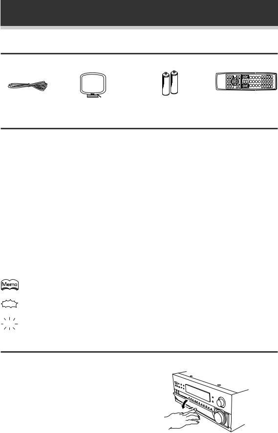
Please check that you have received all of the following supplied accessories.
FM wire antenna |
AM loop antenna |
“AA” IEC LR6 batteries × 2 |
Remote control unit |
How to Use This Manual
This manual is for the VSX-D938TX/D908TX/D908TX-G Audio/Video Multi-Channel Receiver.
This manual is divided into two main sections which will tell you how to setup and use the unit :
PREPARATION
First carry out the tasks below in this “Before You Start” section to prepare the remote control, then connect the receiver to your other components as described in “Connecting Your Equipment” (p.8). Take special care to connect your digital equipment like DVDs and LDs players properly to be able to take advantage of the receiver’s surround sound systems.
To learn about a specific button, control, or indicator, see “Displays and Controls” starting on p.18.
SET UP
Performing the tasks in “Surround Sound Set Up” (p.27) is essential to get proper surround sound.
OPERATION
To play some music or soundtrack refer to “Basic Playback” on p.38. “Using the Tuner” (p.50) explains how to use the radio of this unit. Doing the operations in “Remote Control of Other Components” (p.54) is highly recommended so you can use this unit’s remote control for all your components. “Using Other Functions” (p.66) explains the other possibilities of the receiver.
“Techno Tidbits & Problem-solving” (p.76) provides detailed technical information and a troubleshooting guide.
The following marks and symbols are used throughout the manual:
Provides additional information, precautions, and advice.
Indicates a blinking button, indicator, or display.
Indicates a steadily lit button, indicator, or display.
Opening the Front Panel
To open the front panel, push gently on the lower third of the panel with your finger.
6
Before You Start
Preparing the Remote Control
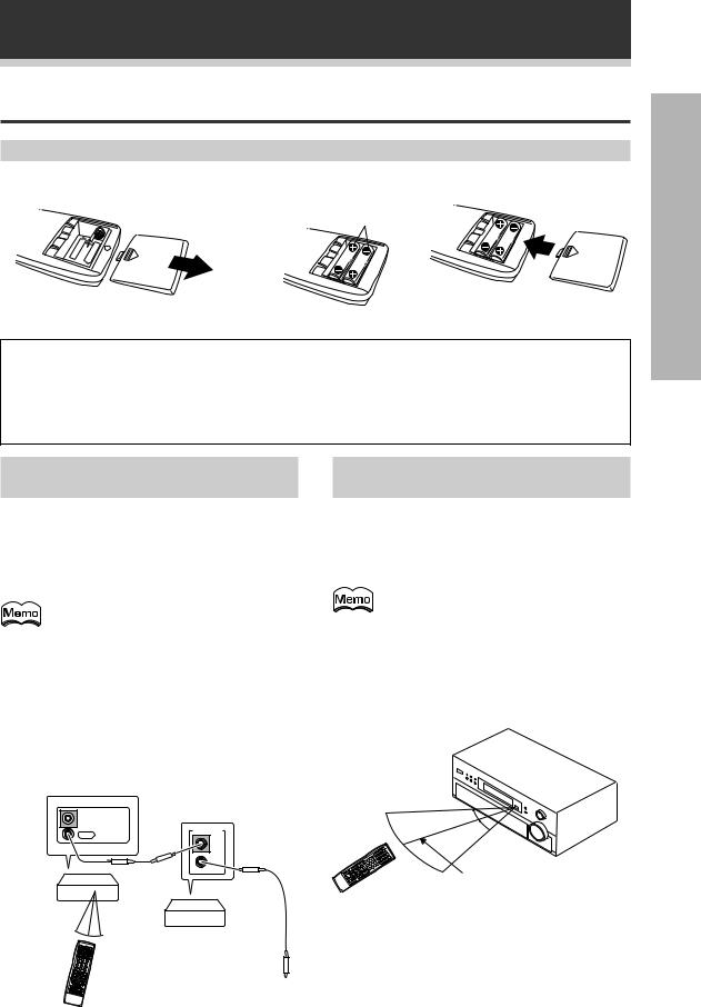
Loading the batteries
Load the batteries into the remote control as shown below. Please use alkaline batteries.
1 |
2 |
AA drycell batteries |
3 |
(("AA" IEC LR6) × 2) |
When you notice a decrease in the operating range of the remote control, replace all batteries with new ones.
CAUTION!
Incorrect use of batteries may result in such hazards as leakage and bursting. Observe the following precautions.
•Never use new and old batteries together.
•Insert the plus and minus sides of the batteries properly according to the marks in the battery case.
•Batteries with the same shape may have different voltages. Do not use different batteries together.
Operating other PIONEER |
Operating range of remote |
components |
control unit |
Connecting an optional control cord allows you to operate other PIONEER components simply by pointing the receiver’s remote control at the remote sensor on the front panel of the receiver. The receiver then sends the remote control signals to the other devices via the CONTROL OUT terminal.
• You can also control PIONEER components (and those made by other manufactures) by pointing the receiver’s remote control directly at the respective component. This type of operation does not require control cords. All you have to do is recall the appropriate preset code (see P.79 (VSX-D938TX), P.83 (VSX- D908TX/D908TX-G)).
•If you use a remote control hooked up via the CONTROL IN jack with a control cord, you will not be able to use this unit’s remote control.
The area in which you can use the remote control to operate the VSX-D938TX/D908TX/D908TX-G is fairly large. To use, point the remote control toward the remote sensor on the front panel of this unit while within the range shown below.
Remote control may not function properly if:
•There are obstacles between the remote control and the remote sensor.
•Direct sunlight or fluorescent light is shining onto the remote sensor.
•The receiver located near a device emitting infrared rays.
•Operated simultaneously with another remote control which uses infrared rays.
IN
CONTROL
CONTROL
OUT
IN
OUT
Receiver
Remote Control
PIONEER component bearing the Î mark.
To CONTROL IN terminal of another PIONEER component bearing the Î mark.
30°
30°
7 m
7
PREPARATION
Connecting Your Equipment
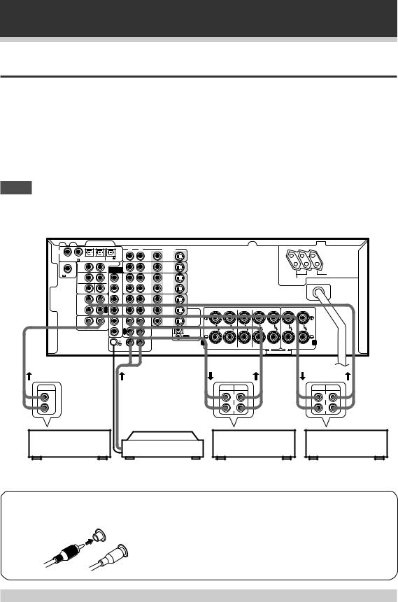
Audio Components
To begin set up, connect your audio components to the jacks as shown below. These are all analog connections and your analog audio components (turntable, cassette deck) use these jacks. Remember that for components you want to record with you need to hook up four plugs (a set of stereo ins and a set of stereo outs), but for components that only play (like a turntable) you only need to hook up one set of stereo plugs (two plugs). To use DTS surround sound features you must hook up your digital components to the digital inputs but it is also a good idea to hook up your digital components to analog audio jacks. If you want to record to/from digital components (like an MD) to/from analog components, you must hook up your digital equipment with these analog connections. See p.10-11 for more on digital connections.
When connecting your equipment, always make sure the power is turned off and the power cord is disconnected from the wall outlet.
NOTE
•Only the VSX-D938TX has a 2RF IN jack.
•The arrows indicate the direction of the audio signal.
|
|
|
|
|
|
|
|
|
|
|
VSX-D938TX (Singaporean model) |
|||
DIGITAL |
|
|
|
|
R |
L |
VIDEO |
|
|
|
|
|
|
AC OUTLETS |
|
|
|
|
|
DVD |
S |
|
|
|
|
|
|
CAUTION: |
|
|
|
|
|
|
|
|
|
|
|
|
|
|||
1 |
2 3 |
4 |
PCM/ /DTS |
|
/LD |
|
|
|
|
|
|
|||
|
IN |
IN |
|
|
|
|
|
|
DO NOT |
|||||
PCM/ |
/DTS IN/MPEG IN |
/MPEG OUT |
|
|
|
|
|
|
|
|
|
CONNECT |
||
|
S |
|
S |
PREOUT |
|
TV/ |
S |
S2 |
|
|
|
|
|
TV SET OR |
|
|
|
|
|
|
|
|
|
MONITOR. |
|||||
|
R |
|
L |
EXTERNAL |
|
SAT |
IN |
IN |
|
|
|
|
|
|
|
|
|
|
DECODER |
|
IN |
|
|
|
|
|
|
|
UNSWITCHED |
|
|
|
|
IN |
|
|
|
|
|
|
|
|
|
|
RF IN |
F |
|
F |
F |
|
|
S |
|
|
|
|
|
|
100W MAX |
|
|
IN |
|
|
|
|
|
SWITCHED |
|
|||||
|
R |
|
L |
L |
|
|
IN |
|
|
|
|
|
|
|
|
|
|
|
|
|
VCR1 |
|
|
|
|
|
TOTAL 100W MAX |
|
|
|
|
|
|
|
|
S |
|
|
|
|
|
|
|
|
|
C |
|
S |
F |
|
OUT |
|
|
|
|
|
|
|
|
|
|
W |
R |
|
OUT |
|
|
|
|
|
|
|
||
|
|
|
|
|
|
|
|
|
|
|
|
|||
|
|
|
P |
S |
|
|
S |
|
|
|
|
|
|
|
|
|
|
L |
|
IN |
|
|
|
|
|
|
|
||
|
|
|
A |
L |
|
|
IN |
|
|
|
|
|
|
|
|
TAPE2 |
|
Y |
|
|
|
|
|
|
|
|
|
|
|
|
MONITOR |
|
|
|
|
VCR2 |
|
|
|
|
|
|
|
|
|
|
|
R |
S |
|
|
S |
|
|
FR FL |
C |
SR SL |
R L |
|
|
|
|
E |
|
OUT |
TO |
|
|
||||||
|
|
|
C |
R |
|
|
OUT |
MONITOR |
|
|
|
|
|
|
|
|
|
|
|
|
|
|
TV |
|
|
|
|
|
|
|
|
|
I |
|
P |
|
|
S |
|
|
|
|
|
|
|
CD |
|
C |
L |
|
VIDEO |
|
|
|
|
|
|
||
|
|
|
N |
|
A |
MD/ |
OUT |
OUT |
|
|
|
|
|
|
|
R |
L |
|
|
Y |
|
|
|
|
|
|
|
|
|
|
|
S |
R |
TAPE1 |
|
IN |
|
|
|
|
|
|
||
|
|
|
|
E |
|
|
|
|
|
|
|
|
||
|
|
|
|
W |
C |
|
|
CONTROL |
|
|
|
|
|
|
|
|
|
|
|
|
|
|
OUT |
|
|
|
|
|
|
|
|
|
|
|
|
IN |
|
|
A |
FRONT |
CENTER |
SURROUND |
FRONT |
B |
|
|
|
|
|
|
PHONO |
|
|
|
SPEAKERS |
SPEAKERS |
SPEAKERS |
SPEAKERS |
|
|
|
|
|
|
|
|
|
|
|
|
|
|
|
|
|
|
|
|
|
|
|
|
|
|
|
|
SEE INSTRUCTION MANUAL |
|
|
OUTPUT |
|
|
|
|
|
|
|
|
|
REC |
PLAY |
|
|
REC PLAY |
L |
|
|
|
|
|
|
|
|
|
L |
|
|
L |
|
R |
|
|
|
|
|
|
|
|
|
R |
|
|
R |
|
CD player |
|
|
|
|
|
|
|
|
MD recorder |
|
Cassette deck |
|||
|
|
|
|
Turntable |
|
or Cassette deck |
|
(with REC monitor) |
||||||
|
|
|
|
|
|
|
|
|||||||
If your turntable has a ground wire, connect it to the SIGNAL GND terminal.
7 Audio cords
Use audio cords (not supplied) to connect the audio components.
R
L
Connect red plugs to R (right) and white plugs to L (left). Be sure to insert completely.
Cassette deck placement
Depending on where the cassette deck is placed, noise may occur during playback of your cassette deck which is caused by leakage flux from the transformer in the receiver. If you experience noise, move the cassette deck farther away from the receiver.
8
Connecting Your Equipment
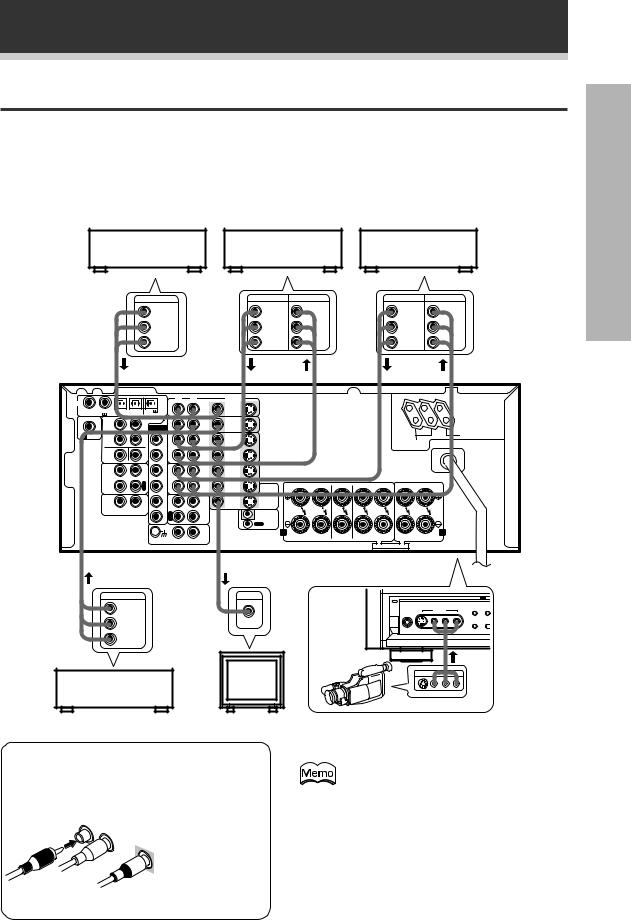
Video Components
Connect your video components to the jacks as shown below. Regarding digital video components (like a DVD), you must use the analog connections pictured on this page for the video signal but in order to use Dolby Digital you should hook up their audio to a digital input (see the next page). It is also a good idea to hook up your digital components with analog audio connections as well (see the previous page). To cover all possible laser discs a DVD/LD player or LD player requires an analog connection (as shown here) and two digital connections (see the next page).
When connecting your equipment always make sure the power is turned off and the power cord is disconnected from the wall outlet.
|
DVD player |
|
|
Video deck (1) |
|
Video deck (2) |
|
|||||||
|
(or LD player) |
|
|
|
|
|||||||||
|
|
|
|
|
|
|
|
|
|
|||||
|
|
|
OUTPUT |
|
|
OUTPUT |
INPUT |
|
|
OUTPUT |
INPUT |
|
||
|
|
|
|
VIDEO |
|
|
VIDEO |
VIDEO |
|
|
VIDEO |
VIDEO |
||
|
|
|
|
L |
|
|
|
L |
L |
|
|
L |
L |
|
|
|
|
|
R |
|
|
|
R |
R |
|
|
R |
R |
VSX-D938TX |
|
|
|
|
|
|
|
|
|
|
|
|
|
|
|
|
|
|
|
|
|
|
|
|
|
|
|
|
|
(Singaporean |
|
|
|
|
|
|
|
|
|
|
|
|
|
|
model) |
DIGITAL |
|
|
|
|
R |
L |
VIDEO |
|
|
|
|
|
|
AC OUTLETS |
|
|
|
|
|
DVD |
S |
|
|
|
|
|
|
CAUTION: |
|
|
|
|
|
|
|
|
|
|
|
|
|
|||
1 |
2 3 |
4 |
PCM/ /DTS |
|
/LD |
|
|
|
|
|
|
|||
|
IN |
IN |
|
|
|
|
|
|
DO NOT |
|||||
PCM/ |
/DTS IN/MPEG IN |
/MPEG OUT |
|
|
|
|
|
|
|
|
|
CONNECT |
||
|
S |
|
S |
PREOUT |
|
TV/ |
S |
S2 |
|
|
|
|
|
TV SET OR |
|
|
|
|
|
|
|
|
|
MONITOR. |
|||||
|
R |
|
L |
EXTERNAL |
|
SAT |
IN |
IN |
|
|
|
|
|
|
|
|
|
IN |
|
|
|
|
|
|
|||||
|
|
|
|
DECODER |
|
|
|
|
|
|
|
|
UNSWITCHED |
|
|
|
|
|
IN |
|
|
|
|
|
|
|
|
|
|
RF IN |
F |
|
F |
F |
|
|
S |
|
|
|
|
|
|
100W MAX |
|
|
IN |
|
|
|
|
SWITCHED |
|
|
|||||
|
R |
|
L |
L |
|
|
IN |
|
|
|
|
|
|
|
|
|
|
|
|
|
VCR1 |
|
|
|
|
|
TOTAL 100W MAX |
|
|
|
C |
|
S |
F |
|
OUT |
S |
|
|
|
|
|
|
|
|
|
W |
R |
|
OUT |
|
|
|
|
|
|
|
||
|
|
|
|
|
|
|
|
|
|
|
|
|||
|
|
|
P |
S |
|
|
S |
|
|
|
|
|
|
|
|
|
|
L |
|
IN |
|
|
|
|
|
|
|
||
|
|
|
A |
L |
|
|
IN |
|
|
|
|
|
|
|
|
TAPE2 |
|
Y |
|
|
|
|
|
|
|
|
|
|
|
|
MONITOR |
|
|
|
|
VCR2 |
|
|
|
|
|
|
|
|
|
|
|
R |
S |
|
|
S |
|
FR FL |
C |
SR SL |
R |
L |
|
|
|
|
E |
|
OUT |
TO |
|
|||||||
|
|
|
C |
R |
|
|
OUT |
MONITOR |
|
|
|
|
|
|
|
|
|
|
|
|
|
|
TV |
|
|
|
|
|
|
|
|
|
I |
|
P |
|
|
S |
|
|
|
|
|
|
|
CD |
|
C |
L |
|
VIDEO |
|
|
|
|
|
|
||
|
|
|
N |
|
A |
MD/ |
OUT |
OUT |
|
|
|
|
|
|
|
R |
L |
|
|
Y |
|
|
|
|
|
|
|
|
|
|
|
S |
R |
TAPE1 |
|
IN |
|
|
|
|
|
|
||
|
|
|
|
|
|
|
|
|
|
|
|
|||
|
|
|
|
W |
E |
|
|
CONTROL |
|
|
|
|
|
|
|
|
|
|
C |
|
|
|
|
|
|
|
|
||
|
|
|
|
|
|
|
|
OUT |
|
|
|
|
|
|
|
|
|
|
|
|
IN |
|
A |
FRONT |
CENTER |
SURROUND |
FRONT |
B |
|
|
|
|
|
|
|
PHONO |
|
|
SPEAKERS |
SPEAKERS |
SPEAKERS |
SPEAKERS |
|
|
|
|
|
|
|
|
|
|
|
|
|
|
|
|
|
|
|
|
|
|
|
|
|
|
|
|
SEE INSTRUCTION MANUAL |
|
|
|
OUTPUT |
INPUT |
7 Front |
|
VIDEO |
|
|
|
||
VIDEO |
|
S-VIDEO VIDEO |
L AUDIO R |
EXTERNAL |
|
|
5-CHANNEL EQUAL POWER OUTPUT |
||
|
|
VIDEO INPUT |
DECODER IN DIRECT |
|
L |
VIDEO |
PHONES |
|
|
|
|
SPEAKERS |
||
R |
|
Video |
|
|
|
camera |
|
|
|
|
|
|
|
|
|
|
(etc.) |
|
|
|
TV |
VIDEO INPUT |
TV tuner |
(monitor) |
V L R |
(or Satellite tuner)
7 Audio/Video cords
Use audio/video cords (not supplied) to connect the video components and a video cord to connect the monitor TV.
R |
|
Connect red |
|
L |
plugs to R (right), |
||
|
|||
|
white plugs to L |
||
|
VIDEO |
||
|
(left), and the |
||
|
|
yellow plugs to |
|
|
|
VIDEO. |
|
|
|
Be sure to insert |
|
|
|
completely. |
Front video connections are accessed via the front panel input selector as “VIDEO.”
If your video components have S-video jacks, you could use S-video cords (not supplied) to connect them on the back of the receiver. These jacks are labeled by the Japanese designation “S2” on the VSX- D938TX/D908TX/D908TX-G but they are simply S-video jacks.
However, if you use S-video cords for your video hook ups you must also hook up your TV with S-video connections. Conversely, if
you use regular composite video cords for |
|
video hook ups, you should use them for |
9 |
your TV as well. |
PREPARATION
Connecting Your Equipment
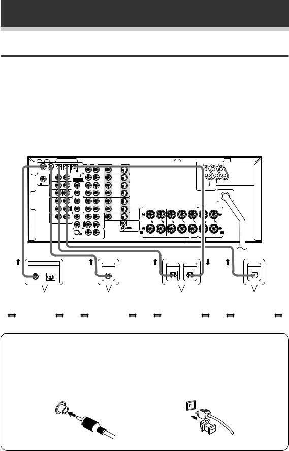
Digital Connections
In order to use Dolby Digital/DTS soundtracks and MPEG audio, you need to make digital audio connections. You can do this by either coaxial or optical connections (you do not need to do both). The quality of these two types of connections is the same but since some digital components only have one type of digital terminal, it is a matter of matching like with like (for example, the coaxial out from the component to coaxial in on the receiver). The VSX-D938TX/D908TX/D908TX-G has two coaxial and two optical inputs for a total of four digital inputs. For the VSX-D938TX, a DVD/LD player or LD player should be connected to a digital jack and the special AC-3 RF jack (if the LD has one) as well as a pair of analog jacks (see the previous page). Connect your digital components as shown below. There is one digital out jack which is marked PCM/2/DTS/MPEG(VSX-D938TX only) OUT. If you connect this to the optical input on a digital recorder (currently these include MD, DAT and CD- R) you can make direct digital recordings with this unit.
When connecting your equipment, always make sure the power is turned off and the power cord is disconnected from the wall outlet.
|
|
|
|
|
|
|
|
|
|
|
|
VSX-D938TX (Singaporean model) |
||||
DIGITAL |
|
|
|
|
|
R |
L |
VIDEO |
|
|
|
|
|
|
|
AC OUTLETS |
|
|
|
|
|
|
DVD |
S |
|
|
|
|
|
|
|
CAUTION: |
|
|
|
|
|
|
|
|
|
|
|
|
|
|
|
|||
1 |
2 |
3 |
4 |
PCM/ /DTS |
|
/LD |
|
|
|
|
|
|
|
|||
|
IN |
IN |
|
|
|
|
|
|
|
DO NOT |
||||||
PCM/ |
/DTS IN/MPEG IN |
/MPEG OUT |
|
|
|
|
|
|
|
|
|
|
CONNECT |
|||
|
S |
|
|
S |
PREOUT |
|
TV/ |
S |
S2 |
|
|
|
|
|
|
TV SET OR |
|
|
|
|
|
|
|
|
|
|
|
MONITOR. |
|||||
|
R |
|
|
L |
EXTERNAL |
|
SAT |
IN |
IN |
|
|
|
|
|
|
|
|
|
|
|
|
DECODER |
|
IN |
|
|
|
|
|
|
|
|
UNSWITCHED |
|
|
|
|
|
IN |
|
|
|
|
|
|
|
|
|
|
|
RF IN |
F |
|
|
F |
F |
|
|
S |
|
|
|
|
|
|
|
100W MAX |
|
|
|
IN |
|
|
|
|
|
|
SWITCHED |
|
|||||
|
R |
|
|
L |
L |
|
|
IN |
|
|
|
|
|
|
|
|
|
|
|
|
|
|
|
VCR1 |
|
|
|
|
|
|
|
TOTAL 100W MAX |
|
|
|
|
|
|
|
|
S |
|
|
|
|
|
|
|
|
|
|
C |
|
|
S |
F |
|
OUT |
|
|
|
|
|
|
|
|
|
|
|
|
W |
R |
|
OUT |
|
|
|
|
|
|
|
|
||
|
|
|
|
|
|
|
|
|
|
|
|
|
|
|||
|
|
|
|
P |
S |
|
|
S |
|
|
|
|
|
|
|
|
|
|
|
|
L |
|
IN |
|
|
|
|
|
|
|
|
||
|
|
|
|
A |
L |
|
|
IN |
|
|
|
|
|
|
|
|
|
TAPE2 |
|
|
Y |
|
|
|
|
|
|
|
|
|
|
|
|
|
MONITOR |
|
|
|
|
VCR2 |
|
|
|
|
|
|
|
|
|
|
|
|
|
|
R |
S |
|
|
S |
|
FR |
FL |
C |
SR |
SL |
R |
L |
|
|
|
|
E |
|
OUT |
TO |
|||||||||
|
|
|
|
C |
R |
|
|
OUT |
MONITOR |
|
|
|
|
|
|
|
|
|
|
|
|
|
|
|
|
TV |
|
|
|
|
|
|
|
|
|
|
|
I |
|
P |
|
|
S |
|
|
|
|
|
|
|
|
CD |
|
|
C |
L |
|
VIDEO |
|
|
|
|
|
|
|
||
|
|
|
|
N |
|
A |
MD/ |
OUT |
OUT |
|
|
|
|
|
|
|
|
|
R |
L |
|
|
Y |
|
|
|
|
|
|
|
|
|
|
|
|
|
S |
R |
TAPE1 |
|
IN |
|
|
|
|
|
|
|
||
|
|
|
|
|
E |
|
|
|
|
|
|
|
|
|
||
|
|
|
|
|
W |
C |
|
|
CONTROL |
|
|
|
|
|
|
|
|
|
|
|
|
|
|
|
|
OUT |
|
|
|
|
|
|
|
|
|
|
|
|
|
|
IN |
|
|
A |
FRONT |
CENTER |
SURROUND |
FRONT |
B |
|
|
|
|
|
|
|
|
PHONO |
|
|
SPEAKERS |
SPEAKERS |
SPEAKERS |
SPEAKERS |
|||
|
|
|
|
|
|
|
|
|
|
|
|
|
|
|
|
|
|
|
|
|
|
|
|
|
|
|
|
|
|
|
SEE INSTRUCTION MANUAL |
|
|
DIGITAL OUT |
|
|
|
|
|
DIGITAL |
|
|
|
DIGITAL |
|
DIGITAL |
|
DIGITAL |
||
OPT. |
|
|
|
|
|
|
|
|
|
|
||||||
|
|
|
|
|
|
OUT |
|
|
|
OUT |
|
IN |
|
OUT |
||
DVD player |
|
CD player |
|
MD recorder |
|
TV tuner |
|
|
|
(or Satellite tuner) |
|||
|
|
|
|
|
|
|
|
|
|
|
|
|
|
7 Digital audio cords/Optical cables
Commercially available digital audio coaxial cords (standard video cords can also be used) or optical cables (not supplied) are used to connect digital components to this receiver.
When you use optical digital input or output terminals, pull off the caps and insert the plugs. Be sure to insert completely.
Digital audio cord |
Optical cable |
|
|
(or standard video cord) |
|
10

Connecting Your Equipment
Example of connection using a DVD/LD or LD player
VSX-D938TX model:
Make sure you connect your DVD/LD or LD players using the AC-3 RF jack. If your player has an AC-3 RF output, this will ensure you can use all types of laser discs. See p. 37.
|
|
|
|
|
|
|
|
|
|
VSX-D938TX (Singaporean model) |
||||||
DIGITAL |
|
|
|
|
|
R |
L |
VIDEO |
|
|
|
|
|
|
|
AC OUTLETS |
|
|
|
|
|
|
DVD |
S |
|
|
|
|
|
|
|
CAUTION: |
|
1 |
2 |
3 |
4 |
PCM/ /DTS |
|
/LD |
|
|
|
|
|
|
|
|||
|
IN |
IN |
|
|
|
|
|
|
|
DO NOT |
||||||
PCM/ |
/DTS IN/MPEG IN |
/MPEG OUT |
|
|
|
|
|
|
|
|
|
|
CONNECT |
|||
|
S |
|
|
S |
PREOUT |
|
SAT |
S |
S2 |
|
|
|
|
|
|
TV SET OR |
|
|
|
|
|
|
|
TV/ |
|
|
|
|
|
|
|
|
MONITOR. |
|
R |
|
|
L |
EXTERNAL |
|
IN |
IN |
IN |
|
|
|
|
|
|
|
|
|
|
|
|
DECODER |
|
|
|
|
|
|
|
|
|
UNSWITCHED |
|
|
|
|
|
|
IN |
|
|
|
|
|
|
|
|
|
|
|
RF IN |
F |
|
|
F |
F |
|
|
S |
|
|
|
|
|
|
|
100W MAX |
|
|
|
IN |
|
|
|
|
|
|
SWITCHED |
|
|||||
|
R |
|
|
L |
L |
|
|
IN |
|
|
|
|
|
|
|
|
|
|
|
|
|
|
|
VCR1 |
|
|
|
|
|
|
|
TOTAL 100W MAX |
|
|
C |
|
|
S |
F |
|
OUT |
S |
|
|
|
|
|
|
|
|
|
|
|
W |
R |
|
OUT |
|
|
|
|
|
|
|
|
||
|
|
|
|
|
|
|
|
|
|
|
|
|
|
|||
|
|
|
|
P |
S |
|
|
S |
|
|
|
|
|
|
|
|
|
|
|
|
L |
|
IN |
|
|
|
|
|
|
|
|
||
|
TAPE2 |
|
|
A |
L |
|
|
IN |
|
|
|
|
|
|
|
|
|
|
|
Y |
|
|
VCR2 |
|
|
|
|
|
|
|
|
|
|
|
MONITOR |
|
|
|
|
|
|
|
|
|
|
|
|
|
||
|
|
|
|
R |
S |
|
OUT |
S |
|
FR |
FL |
C |
SR |
SL |
R |
L |
|
|
|
|
E |
R |
|
TO |
|||||||||
|
|
|
|
C |
|
|
OUT |
|
|
|
|
|
|
|
||
|
|
|
|
|
|
|
|
MONITOR |
|
|
|
|
|
|
|
|
|
|
|
|
|
|
|
|
|
TV |
|
|
|
|
|
|
|
|
|
|
|
I |
|
P |
|
|
S |
|
|
|
|
|
|
|
|
CD |
|
|
C |
L |
|
VIDEO |
|
|
|
|
|
|
|
||
|
|
|
|
N |
|
A |
MD/ |
OUT |
OUT |
|
|
|
|
|
|
|
|
|
R |
L |
|
|
Y |
|
|
|
|
|
|
|
|
|
|
|
|
|
S |
R |
TAPE1 |
|
IN |
|
|
|
|
|
|
|
||
|
|
|
|
|
W |
E |
|
|
|
|
|
|
|
|
|
|
|
|
|
|
|
C |
|
|
CONTROL |
|
|
|
|
|
|
|
|
|
|
|
|
|
|
|
|
|
OUT |
|
|
|
|
|
|
|
|
|
|
|
|
|
|
IN |
|
|
A |
FRONT |
CENTER |
SURROUND |
FRONT |
B |
|
|
|
|
|
|
|
|
|
|
|
|||||||
|
|
|
|
|
|
|
PHONO |
|
|
SPEAKERS |
SPEAKERS |
SPEAKERS |
SPEAKERS |
|||
|
|
|
|
|
|
|
|
|
|
|
|
|
|
|
|
|
|
|
|
|
|
|
|
|
|
|
|
|
|
|
SEE INSTRUCTION MANUAL |
|
|
 RF OUT (AC-3)(LD)
OUTPUT
DIGITAL OUT
PCM (OPT.)
VIDEO
1
L 
2 3
R
DVD/LD player or LD player
VSX-D908TX/D908TX-G models:
Be sure to make either a digital coaxial or digital optical connection (pictured as DIGITAL jack 1 or DIGITAL jack 3 in this diagram) as well, but you DO NOT need to make both. Also, be sure to assign the jacks to the proper component(s) with the “Digital-In Select” procedure (see p.37).
When playing LD recorded in Dolby Digital
To connect a DVD/LD or LD player with its AC-3 RF output, a commercially available RF demodulator (RFD-1) is required. The RF demodulator changes the RF signal to a digital signal which is then processed by the VSX- D908TX/D908TX-G models through their digital input jacks. For more details, refer to the instruction manual supplied with the RFD-1.
|
|
|
|
|
|
|
|
|
|
|
VSX-D908TX/D908TX-G |
|
|||
DIGITAL |
|
|
|
R |
L |
VIDEO |
|
|
|
|
|
|
|
AC OUTLETS |
|
|
|
|
|
DVD |
S |
|
|
|
TWO VOLTAGE SELECTORS |
|
CAUTION: |
|
|||
1 |
2 |
3 4 PCM/ /DTS |
|
/LD |
|
|
|
|
|
|
|
|
|||
|
IN |
IN |
|
|
|
|
|
|
|
DO NOT |
|
||||
|
PCM/ |
/DTS IN |
OUT |
|
|
|
|
|
|
|
|
|
|
CONNECT |
|
|
|
|
|
|
TV/ |
S |
S2 |
|
|
|
|
|
|
TV SET OR |
|
PREOUT |
S |
S |
|
|
|
|
|
|
|
|
MONITOR. |
|
|||
EXTERNAL |
|
SAT |
|
|
|
|
|
|
|
|
|||||
|
R |
L |
|
IN |
IN |
IN |
|
|
|
|
|
|
|
|
|
|
|
|
DECODER |
|
|
|
|
|
|
|
|
|
|
|
|
|
|
|
IN |
|
|
|
|
|
|
|
|
|
|
UNSWITCHED |
|
|
F |
F |
F |
|
IN |
S |
|
|
|
220V |
240V |
|
|
||
|
|
|
|
|
|
|
|
|
100W MAX |
|
|||||
|
R |
L |
L |
|
|
IN |
|
|
|
|
110V 120V-127V |
SWITCHED |
|
||
|
|
|
|
|
VCR1 |
|
|
|
|
|
110V |
220V |
TOTAL |
|
|
|
|
S |
F |
|
|
S |
|
|
|
|
100W MAX |
|
|||
|
C |
|
OUT |
|
|
|
|
120V-127V |
240V |
|
|
|
|||
|
W |
R |
|
OUT |
|
|
|
|
|
|
|
|
|
||
|
|
|
|
|
|
|
|
|
|
|
|
|
|||
|
|
P |
S |
|
|
S |
|
|
|
|
|
|
|
|
|
|
|
L |
|
IN |
|
|
|
|
|
|
|
|
|
||
|
TAPE2 |
A |
L |
|
|
IN |
|
|
|
|
|
|
|
|
|
|
Y |
|
|
VCR2 |
|
|
|
|
|
|
|
|
|
|
|
|
MONITOR |
|
|
|
|
|
|
|
|
|
|
|
|
||
|
|
R |
S |
|
OUT |
S |
|
FR |
FL |
C |
SR |
SL |
R |
L |
|
|
|
E |
R |
|
TO |
|
|||||||||
|
|
C |
|
|
OUT |
|
|
|
|
|
|
|
|
||
|
|
|
|
|
|
MONITOR |
|
|
|
|
|
|
|
|
|
|
|
|
|
P |
|
|
TV |
|
|
|
|
|
|
|
|
|
|
I |
|
|
|
S |
|
|
|
|
|
|
|
|
|
|
CD |
C |
L |
|
VIDEO |
|
|
|
|
|
|
|
|
||
|
|
N |
|
A |
MD/ |
OUT |
OUT |
|
|
|
|
|
|
|
|
|
|
|
|
Y |
|
|
|
|
|
|
|
|
|
|
|
|
|
|
|
R |
TAPE1 |
|
|
|
|
|
|
|
|
|
|
|
|
|
S |
|
|
IN |
|
|
|
|
|
|
|
|
|
|
|
|
W |
E |
|
|
|
|
|
|
|
|
|
|
|
|
|
|
C |
|
|
CONTROL |
|
|
|
|
|
|
|
|
|
|
|
|
|
|
|
|
OUT |
|
|
|
|
|
|
|
|
|
|
|
|
|
IN |
|
A |
|
FRONT |
CENTER |
SURROUND |
FRONT |
B |
|
|
|
|
|
|
|
|
|
|
|
|||||||
|
|
|
|
|
PHONO |
|
|
SPEAKERS |
SPEAKERS |
SPEAKERS |
SPEAKERS |
|
|||
|
|
|
|
|
|
|
|
|
|
|
|
|
|
|
|
|
|
|
|
|
|
|
|
|
|
|
|
SEE INSTRUCTION MANUAL |
|
|
|
|
|
|
|
|
|
|
|
|
|
|
|
RF OUT |
|
|
|
|
|
|
|
|
|
|
|
|
|
|
(AC-3)(LD) |
|
|
|
|
|
|
|
|
|
|
|
|
|
|
|
|
|
|
OUTPUT |
|
|
|
|
|
|
|
|
|
|
|
|
|
|
DIGITAL OUT |
Make sure the RF |
|
|
|
|
|
|
|
|
|
|
|
|
1 |
PCM (OPT.) |
VIDEO |
||
|
|
|
|
|
|
|
|
|
|
|
|
|
|
demodulator |
|
|
PCM/ |
PCM/ |
PCM/ |
PCM/ |
|
|
|
|
|
|
|
|
|
L |
|
|
(AC-3)(LD) |
|
|
|
|
|
|
|
|
digital in switch is |
|||||
|
(OPT.) |
|
(OPT.) |
|
|
|
|
|
2 |
3 |
|
|
|||
|
DIGITAL OUT |
DIGITAL IN |
|
RF IN |
|
|
|
|
|
R |
|
||||
|
|
|
|
|
|
|
|
|
|
||||||
|
|
|
|
|
|
|
|
|
|
|
|
|
|
set correctly |
|
|
|
|
|
|
|
|
|
|
|
|
|
|
|
|
|
|
|
|
|
|
|
|
|
|
|
|
|
|
|
|
(optical or coaxial |
|
|
|
|
|
|
|
|
|
|
DVD/LD player |
depending on the |
||||
|
|
|
|
|
|
DIGITAL IN |
|
|
connection). |
||||||
|
|
|
|
|
|
|
|
|
|
|
or LD player |
||||
|
|
|
|
|
|
OPTICAL |
COAXIAL |
|
|
|
|
||||
|
|
|
|
|
|
|
|
|
|
|
|
|
|
||
PREPARATION
RF demodulator RFD-1 |
11 |
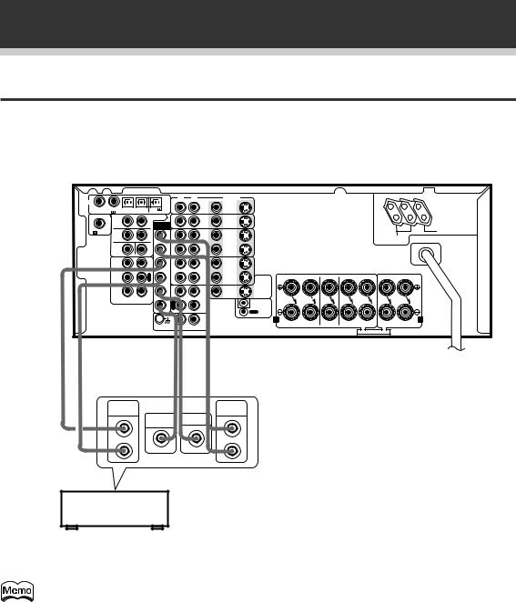
Connecting Your Equipment
External Decoder Input
In some cases you may need an external decoder to play special analog or DVD sources. If you find you need an external decoder hook one up as shown below, but for most people this component is unnecessary. (See p.47) When connecting your equipment always make sure the power is turned off and the power cord is disconnected from the wall outlet.
|
|
|
|
|
|
|
|
|
|
|
|
VSX-D938TX (Singaporean model) |
||||
DIGITAL |
|
|
|
|
|
R |
L |
VIDEO |
|
|
|
|
|
|
|
AC OUTLETS |
|
|
|
|
|
|
DVD |
S |
|
|
|
|
|
|
|
CAUTION: |
|
|
|
|
|
|
|
|
|
|
|
|
|
|
|
|||
1 |
2 |
3 |
4 |
PCM/ /DTS |
|
/LD |
|
|
|
|
|
|
|
|||
|
IN |
IN |
|
|
|
|
|
|
|
DO NOT |
||||||
PCM/ |
/DTS IN/MPEG IN |
/MPEG OUT |
|
|
|
|
|
|
|
|
|
|
CONNECT |
|||
|
S |
|
|
S |
PREOUT |
|
TV/ |
S |
S2 |
|
|
|
|
|
|
TV SET OR |
|
|
|
|
|
|
|
|
|
|
|
MONITOR. |
|||||
|
R |
|
|
L |
EXTERNAL |
|
SAT |
IN |
IN |
|
|
|
|
|
|
|
|
|
|
|
IN |
|
|
|
|
|
|
|
|||||
|
|
|
|
|
DECODER |
|
|
|
|
|
|
|
|
|
UNSWITCHED |
|
|
|
|
|
|
IN |
|
|
|
|
|
|
|
|
|
|
|
RF IN |
F |
|
|
F |
F |
|
|
S |
|
|
|
|
|
|
|
100W MAX |
|
|
|
IN |
|
|
|
|
|
|
SWITCHED |
|
|||||
|
R |
|
|
L |
L |
|
|
IN |
|
|
|
|
|
|
|
|
|
|
|
|
|
|
|
VCR1 |
|
|
|
|
|
|
|
TOTAL 100W MAX |
|
|
C |
|
|
S |
F |
|
OUT |
S |
|
|
|
|
|
|
|
|
|
|
|
W |
R |
|
OUT |
|
|
|
|
|
|
|
|
||
|
|
|
|
|
|
|
|
|
|
|
|
|
|
|||
|
|
|
|
P |
S |
|
|
S |
|
|
|
|
|
|
|
|
|
|
|
|
L |
|
IN |
|
|
|
|
|
|
|
|
||
|
|
|
|
A |
L |
|
|
IN |
|
|
|
|
|
|
|
|
|
TAPE2 |
|
|
Y |
|
|
|
|
|
|
|
|
|
|
|
|
|
MONITOR |
|
|
|
|
VCR2 |
|
|
|
|
|
|
|
|
|
|
|
|
|
|
R |
S |
|
|
S |
|
FR |
FL |
C |
SR |
SL |
R |
L |
|
|
|
|
E |
|
OUT |
TO |
|||||||||
|
|
|
|
C |
R |
|
|
OUT |
MONITOR |
|
|
|
|
|
|
|
|
|
|
|
|
|
|
|
|
TV |
|
|
|
|
|
|
|
|
|
|
|
I |
|
P |
|
|
S |
|
|
|
|
|
|
|
|
CD |
|
|
C |
L |
|
VIDEO |
|
|
|
|
|
|
|
||
|
|
|
|
N |
|
A |
MD/ |
OUT |
OUT |
|
|
|
|
|
|
|
|
|
R |
L |
|
|
Y |
|
|
|
|
|
|
|
|
|
|
|
|
|
S |
R |
TAPE1 |
|
IN |
|
|
|
|
|
|
|
||
|
|
|
|
|
E |
|
|
|
|
|
|
|
|
|
||
|
|
|
|
|
W |
C |
|
|
CONTROL |
|
|
|
|
|
|
|
|
|
|
|
|
|
|
|
|
OUT |
|
|
|
|
|
|
|
|
|
|
|
|
|
|
IN |
|
|
A |
FRONT |
CENTER |
SURROUND |
FRONT |
B |
|
|
|
|
|
|
|
|
PHONO |
|
|
SPEAKERS |
SPEAKERS |
SPEAKERS |
SPEAKERS |
|||
|
|
|
|
|
|
|
|
|
|
|
|
|
|
|
|
|
|
|
|
|
|
|
|
|
|
|
|
|
|
|
SEE INSTRUCTION MANUAL |
|
|
» |
» » » |
|
SURROUND |
|
FRONT |
OUTPUT |
SUB |
OUTPUT |
|
CENTER |
|
|
WOOFER |
|
|
|
|
L |
|
L |
R |
|
R |
Components equipped with 5.1 channel analog output jacks
You cannot use the tuner and phono functions with an external decoder input.
12
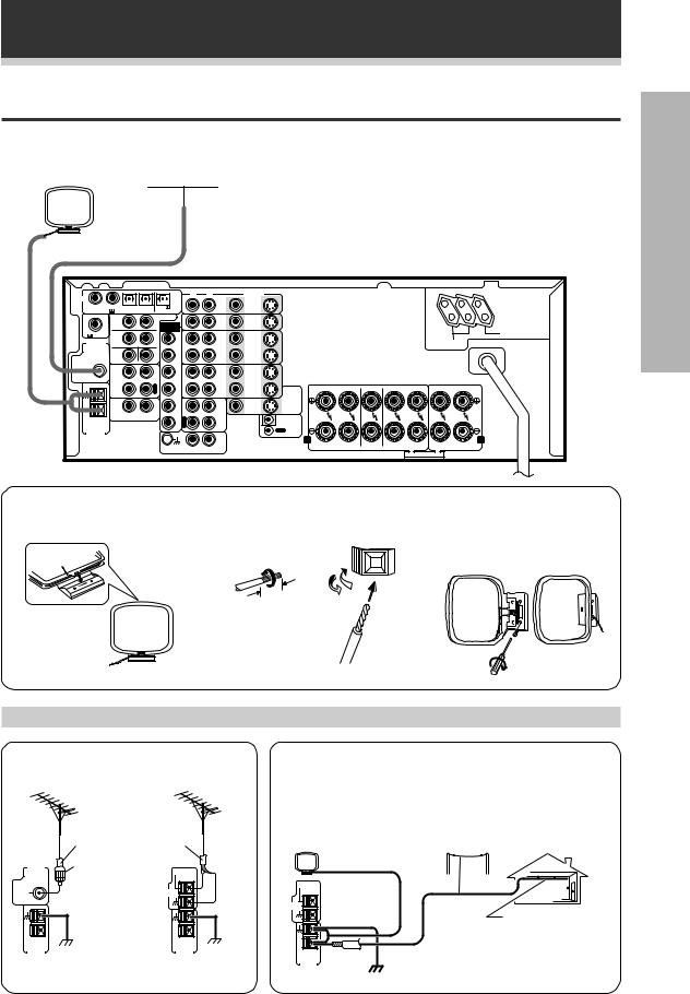
Connecting Your Equipment
Antennas
Hook up the supplied radio antennas as shown below. When connecting your equipment, always make sure the power is turned off and the power cord is disconnected from the wall outlet.
AM loop antenna |
FM wire antenna |
|
|
|
|
|
|
|
|
|||||
|
|
|
|
|
|
Connect the FM wire antenna and fully extend to the “T” shape. |
||||||||
|
|
|
|
|
|
(For best reception, attach horizontally along a window frame, etc.) |
||||||||
(See below) |
|
|
|
|
|
|
|
|
|
VSX-D938TX (Singaporean model) |
||||
|
|
|
|
|
|
|
|
|
|
|
||||
DIGITAL |
|
|
|
|
R |
L |
VIDEO |
|
|
|
|
|
|
AC OUTLETS |
|
|
|
|
|
DVD |
S |
|
|
|
|
|
|
CAUTION: |
|
|
|
|
|
|
|
|
|
|
|
|
|
|||
1 |
2 3 |
4 |
PCM/ /DTS |
|
/LD |
|
|
|
|
|
|
|||
|
IN |
IN |
|
|
|
|
|
|
DO NOT |
|||||
PCM/ |
/DTS IN/MPEG IN |
/MPEG OUT |
|
|
|
|
|
|
|
|
|
CONNECT |
||
|
S |
|
S |
PREOUT |
|
TV/ |
S |
S2 |
|
|
|
|
|
TV SET OR |
|
|
|
|
|
|
|
|
|
MONITOR. |
|||||
|
R |
|
L |
EXTERNAL |
|
SAT |
IN |
IN |
|
|
|
|
|
|
|
|
|
|
DECODER |
|
IN |
|
|
|
|
|
|
|
UNSWITCHED |
|
|
|
|
IN |
|
|
|
|
|
|
|
|
|
|
RF IN |
F |
|
F |
F |
|
|
S |
|
|
|
|
|
|
100W MAX |
|
|
IN |
|
|
|
|
|
SWITCHED |
|
|||||
FM |
R |
|
L |
L |
|
|
IN |
|
|
|
|
|
|
|
ANTENNA |
|
|
|
|
|
VCR1 |
|
|
|
|
|
|
TOTAL 100W MAX |
|
|
|
|
|
|
|
S |
|
|
|
|
|
|
|
|
|
C |
|
S |
F |
|
OUT |
|
|
|
|
|
|
|
|
|
|
W |
R |
|
OUT |
|
|
|
|
|
|
|
||
|
|
|
|
|
|
|
|
|
|
|
|
|||
FM |
|
|
P |
S |
|
|
S |
|
|
|
|
|
|
|
UNBAL |
|
|
L |
|
IN |
|
|
|
|
|
|
|
||
75Ω |
|
|
A |
L |
|
|
IN |
|
|
|
|
|
|
|
|
TAPE2 |
|
Y |
|
|
|
|
|
|
|
|
|
|
|
|
MONITOR |
|
|
|
|
VCR2 |
|
|
|
|
|
|
|
|
|
|
|
R |
S |
|
|
S |
|
|
FR FL |
C |
SR SL |
R L |
|
|
|
|
E |
|
OUT |
TO |
|
|
||||||
|
|
|
C |
R |
|
|
OUT |
MONITOR |
|
|
|
|
|
|
|
|
|
|
|
|
|
|
TV |
|
|
|
|
|
|
|
|
|
I |
|
P |
|
|
S |
|
|
|
|
|
|
|
CD |
|
C |
L |
|
VIDEO |
|
|
|
|
|
|
||
|
|
|
N |
|
A |
MD/ |
OUT |
OUT |
|
|
|
|
|
|
|
R |
L |
|
|
Y |
|
|
|
|
|
|
|
|
|
|
|
S |
R |
TAPE1 |
|
IN |
|
|
|
|
|
|
||
|
|
|
|
E |
|
|
|
|
|
|
|
|
||
AM LOOP |
|
|
|
W |
C |
|
|
CONTROL |
|
|
|
|
|
|
|
|
|
|
|
|
|
OUT |
|
|
|
|
|
|
|
ANTENNA |
|
|
|
|
|
|
|
|
A |
|
|
|
|
B |
|
|
|
|
|
|
IN |
|
|
FRONT |
CENTER |
SURROUND |
FRONT |
||
|
|
|
|
|
|
PHONO |
|
|
|
SPEAKERS |
SPEAKERS |
SPEAKERS |
SPEAKERS |
|
|
|
|
|
|
|
|
|
|
|
|
|
|
|
|
|
|
|
|
|
|
|
|
|
|
|
|
SEE INSTRUCTION MANUAL |
|
|
7 AM loop antenna
1 Assemble the antenna. |
2 Twist exposed wire strands |
3 Attach to a wall, etc. (if |
|
|
together and insert. |
desired) and face toward the |
|
|
|
|
direction providing the best |
|
|
|
reception. |
|
10 |
mm |
|
|
|
|
|
PREPARATION
Using external antennas
7 To improve FM reception
Connect an external FM antenna.
|
75 Ω coaxial cable |
|
FM |
PAL |
|
ANTENNA |
connector |
FM UNBAL |
|
75Ω |
|
|
|
|
FM |
|
FM |
|
UNBAL |
|
ANTENNA |
|
75Ω |
|
|
|
|
|
|
|
AM LOOP |
GND |
AM LOOP |
GND |
ANTENNA |
ANTENNA |
(Singaporean |
(Others) |
model only) |
|
7 To improve AM reception
Connect a 5~6 meter length of vinyl-coated wire to the AM antenna terminal in addition to the supplied AM loop antenna.
For the best possible reception, suspend horizontally outdoors.
FM UNBAL |
|
75Ω |
|
ANTENNA |
5~6 m |
FM |
|
|
Indoor antenna |
|
(Vinyl-coated |
|
wire) |
AM LOOP |
ground |
ANTENNA |
|
|
13
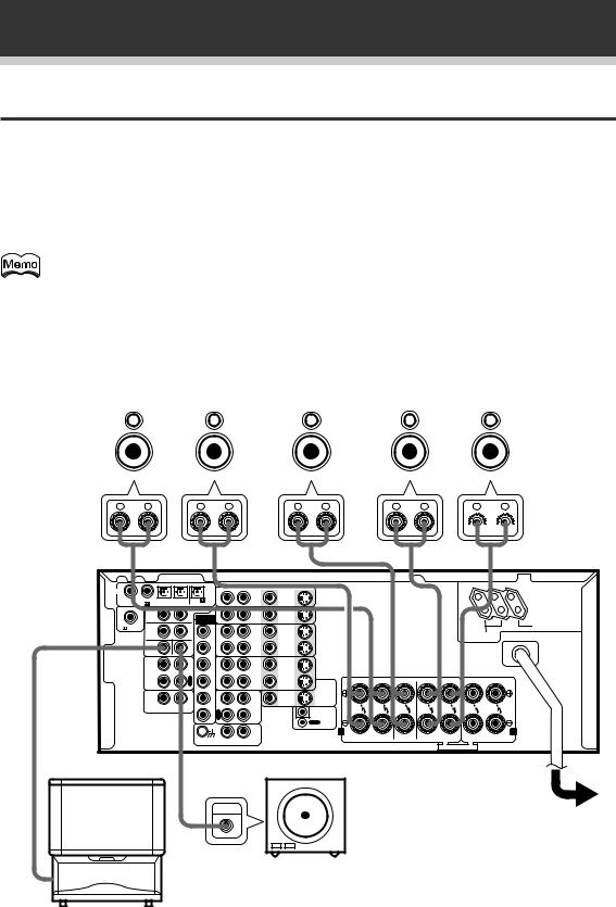
Connecting Your Equipment
Speakers
A full complement of six speakers is shown here but, naturally, everyone’s home set up will vary. Simply connect the speakers you have in the manner described below. The VSX-D938TX/D908TX/D908TX-G will work with just two stereo speakers (called “front” speakers in the diagram) but the receiver is designed to be used with at least three speakers.
Make sure you connect the speaker on the right to the right terminal and the speaker on the left to the left terminal. Also make sure the positive and negative (+/–) terminals on the receiver match those on the speakers. When connecting your equipment, always make sure the power is turned off and the power cord is disconnected from the wall outlet.
The VSX-D938TX/D908TX/D908TX-G has two speaker systems, A & B. A is the main system supporting the full complement of surround sound speakers. If you switch on both A & B speaker systems, only front speakers and the sub-woofer will be audible. No sound will come from the center or surround speakers but multi channel sources will be down-mixed to the active speakers so no sound will be lost. Similarly, if you choose just the B system, you will only hear the front speakers connected to the B system and multi channel sources will be down-mixed to these two speakers.
|
Front Speakers (A) |
Center Speaker |
|
|
Rear Speakers |
|||||||||||||||||||||||||||||||||
|
|
L |
|
|
|
R |
|
|
|
C |
|
|
SR |
|
|
|
SL |
|||||||||||||||||||||
|
|
|
|
|
|
|
|
|
|
|
|
|
|
|
|
|
|
|
|
|
|
|
|
|
|
|
|
|
|
|
|
|
|
|
|
|
|
|
|
|
|
|
|
|
|
|
|
|
|
|
|
|
|
|
|
|
|
|
|
|
|
|
|
|
|
|
|
|
|
|
|
|
|
|
|
|
|

 VSX-D938TX (Singaporean model)
DIGITAL |
|
|
|
|
|
R |
L |
VIDEO |
|
|
|
|
|
|
|
AC OUTLETS |
|
|
|
|
|
|
DVD |
S |
|
|
|
|
|
|
|
CAUTION: |
|
|
|
|
|
|
|
|
|
|
|
|
|
|
|
|||
1 |
2 |
3 |
4 |
PCM/ /DTS |
|
/LD |
|
|
|
|
|
|
|
|||
|
IN |
IN |
|
|
|
|
|
|
|
DO NOT |
||||||
PCM/ |
/DTS IN/MPEG IN |
/MPEG OUT |
|
|
|
|
|
|
|
|
|
|
CONNECT |
|||
|
S |
|
|
S |
PREOUT |
|
TV/ |
S |
S2 |
|
|
|
|
|
|
TV SET OR |
|
|
|
|
|
|
|
|
|
|
|
MONITOR. |
|||||
|
R |
|
|
L |
EXTERNAL |
|
SAT |
IN |
IN |
|
|
|
|
|
|
|
|
|
|
|
IN |
|
|
|
|
|
|
|
|||||
|
|
|
|
|
DECODER |
|
|
|
|
|
|
|
|
|
UNSWITCHED |
|
|
|
|
|
|
IN |
|
|
|
|
|
|
|
|
|
|
|
RF IN |
F |
|
|
F |
F |
|
|
S |
|
|
|
|
|
|
|
100W MAX |
|
|
|
IN |
|
|
|
|
|
|
SWITCHED |
|
|||||
|
R |
|
|
L |
L |
|
|
IN |
|
|
|
|
|
|
|
|
|
|
|
|
|
|
|
VCR1 |
|
|
|
|
|
|
|
TOTAL 100W MAX |
|
|
C |
|
|
S |
F |
|
OUT |
S |
|
|
|
|
|
|
|
|
|
|
|
W |
R |
|
OUT |
|
|
|
|
|
|
|
|
||
|
|
|
|
|
|
|
|
|
|
|
|
|
|
|||
|
|
|
|
P |
S |
|
|
S |
|
|
|
|
|
|
|
|
|
|
|
|
L |
|
IN |
|
|
|
|
|
|
|
|
||
|
|
|
|
A |
L |
|
|
IN |
|
|
|
|
|
|
|
|
|
TAPE2 |
|
|
Y |
|
|
|
|
|
|
|
|
|
|
|
|
|
MONITOR |
|
|
|
|
VCR2 |
|
|
|
|
|
|
|
|
|
|
|
|
|
|
R |
S |
|
|
S |
|
FR |
FL |
C |
SR |
SL |
R |
L |
|
|
|
|
E |
|
OUT |
TO |
|||||||||
|
|
|
|
C |
R |
|
|
OUT |
MONITOR |
|
|
|
|
|
|
|
|
|
|
|
|
|
|
|
|
TV |
|
|
|
|
|
|
|
|
|
|
|
I |
|
P |
|
|
S |
|
|
|
|
|
|
|
|
CD |
|
|
C |
L |
|
VIDEO |
|
|
|
|
|
|
|
||
|
|
|
|
N |
|
A |
MD/ |
OUT |
OUT |
|
|
|
|
|
|
|
|
|
R |
L |
|
|
Y |
|
|
|
|
|
|
|
|
|
|
|
|
|
S |
R |
TAPE1 |
|
IN |
|
|
|
|
|
|
|
||
|
|
|
|
|
E |
|
|
|
|
|
|
|
|
|
||
|
|
|
|
|
W |
C |
|
|
CONTROL |
|
|
|
|
|
|
|
|
|
|
|
|
|
|
|
|
OUT |
|
|
|
|
|
|
|
|
|
|
|
|
|
|
IN |
|
|
A |
FRONT |
CENTER |
SURROUND |
FRONT |
B |
|
|
|
|
|
|
|
|
PHONO |
|
|
SPEAKERS |
SPEAKERS |
SPEAKERS |
SPEAKERS |
|||
|
|
|
|
|
|
|
|
|
|
|
|
|
|
|
|
|
|
|
|
|
|
|
|
|
|
|
|
|
|
|
SEE INSTRUCTION MANUAL |
|
|
Powered sub woofer
INPUT
Be sure to complete all other connections before connecting this unit to the AC power source.
When using the speaker on your TV as the center speaker, connect the CENTER PREOUT jack on this unit to the audio input jack on your TV. In this case, the center speaker shown is unnecessary.
14
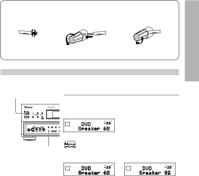
|
|
Connecting Your Equipment |
|
|
|
|
|
|
7 Speaker terminals |
|
|
1 Twist exposed wire |
2 Loosen speaker |
3 Tighten terminal. |
strands together. |
terminal and insert |
|
|
exposed wire. |
|
10 mm
Speaker impedance
You can change the speaker impedance to suit the kind of speakers you have in your home system but we recommend using speakers with an impedance of 8 Ω-16 Ω (the default setting). If you are using 6 Ω-less than 8Ω impedance speakers, you need to change the impedance setting.
w STANDBY/ON |
|
|
|
|
First turn the receiver off, then press the power button |
|||
|
VSX-D938TX |
|||||||
|
|
|
|
|
while holding down the SPEAKERS button. |
|
||
AUDIO/VIDEO MULTI-CHANNEL RECEIVER |
Digital |
Choose the impedance setting by pressing the SPEAKERS button again. |
||||||
|
|
|
|
|
||||
STANDBY/ON |
DSP |
STEREO |
|
|
You can choose the 8 Ω-16 Ω setting or the 6 Ω-8 Ω setting. |
|
||
STANDBY |
MODE |
|
|
|
||||
|
/DTS |
|
|
|
|
|
|
|
THX CINEMA ADVANCED |
STANDARD |
|
|
|
|
|
|
|
|
|
MPEG |
|
|
|
|
|
|
|
|
|
|
|
SIGNAL |
VOLUME |
(This display indicates an 6 Ω-less than |
|
|
|
|
|
|
SELECT |
dB |
||
|
|
|
|
|
ANALOG SP A |
|||
5-CHANNEL EQUAL POWER OUTPUT |
EXTERNAL |
|
|
|
8 Ω impedance setting) |
|
||
PHONES |
VIDEO INPUT |
|
DECODER IN DIRECT LOUDNESS MIDN |
|
|
|
||
S-VIDEO |
VIDEO L |
AUDIO R |
|
|
|
|
|
|
|
|
|
SPEAKERS |
– BASS + |
|
|
|
|
|
SPEAKERS |
|
To check which impedance the amplifier is set to hold down |
|||||
|
|
the SPEAKERS button for 2-3 seconds. You willl get a display |
||||||
|
|
|
|
|
|
like the one shown below right telling you the speaker |
|
|
|
|
|
|
|
|
impedance setting. |
|
|
|
|
|
|
|
SIGNAL |
VOLUME |
SIGNAL |
VOLUME |
|
|
|
|
|
SELECT |
|
SELECT |
|
|
|
|
|
|
ANALOG SP A |
|
ANALOG SP A |
|
|
|
|
|
|
|
dB |
or |
dB |
|
|
|
|
|
|
|
|
|
|
|
|
|
|
(This display indicates a 6 Ω-less |
(This display indicates an 8 Ω-16 Ω |
||
|
|
|
|
|
than 8 Ω impedance setting) |
impedance setting) |
|
|
PREPARATION
15
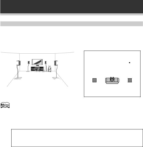
Connecting Your Equipment
Speaker placement
If you have a multiple speaker arrangement the placement of the speakers is extremely important. To achieve the best possible surround sound, install your speakers as shown below. Make sure all speakers are installed securely to prevent accidents and improve sound quality. Be sure to consult your speaker manuals for the best placement of the speakers. Some speakers are designed to be floor-standing but others benefit greatly from speakers stands which raise them off the floor.
|
|
|
|
|
|
|
|
|
|
|
|
|
|
|
Front |
Center |
Front |
|||||
|
|
|
|
|
|
|
|
|
|
|
|
|
|
|
|
Left |
Right |
|||||
|
|
|
|
|
|
|
|
|
|
|
|
|
|
|
|
|
|
|
|
|
|
|
|
|
|
|
|
|
|
|
|
|
|
|
|
|
|
|
|
|
|
|
|
|
|
|
|
|
|
|
|
|
|
|
|
|
|
|
|
|
|
|
|
|
|
|
|
|
|
|
|
|
|
|
|
|
|
|
|
|
|
|
|
|
|
|
|
|
|
|
|
|
|
|
|
|
|
|
|
|
|
|
|
|
|
|
|
|
|
|
|
|
|
|
Sub
Woofer
Surround |
Listening |
Surround |
|
Left |
Right |
||
Position |
|||
|
|
• Install the left and right front speakers at equal distances from the TV.
•When installing speakers near the TV, we recommend using magnetically shielded speakers to prevent possible interference such as distortion in the color of the TV screen. If you do not have magnetically shielded speakers and notice discoloration of the TV screen, place the speakers farther away from the TV.
•Install the center speaker above or below the TV so that the sound of the center channel is localized at the TV screen.
CAUTION:
When installing the center speaker on top of the TV, be sure to secure it with tape or some other suitable means. Otherwise, the speaker may fall from the TV due to external shocks such as earthquakes, and it may lead to endangering those nearby or damaging the speaker.
•If possible, install the surround speakers slightly above ear level.
•It may be difficult to obtain a cohesive surround effect if the surround speakers are installed farther away from the listening position than the front and center speakers.
16
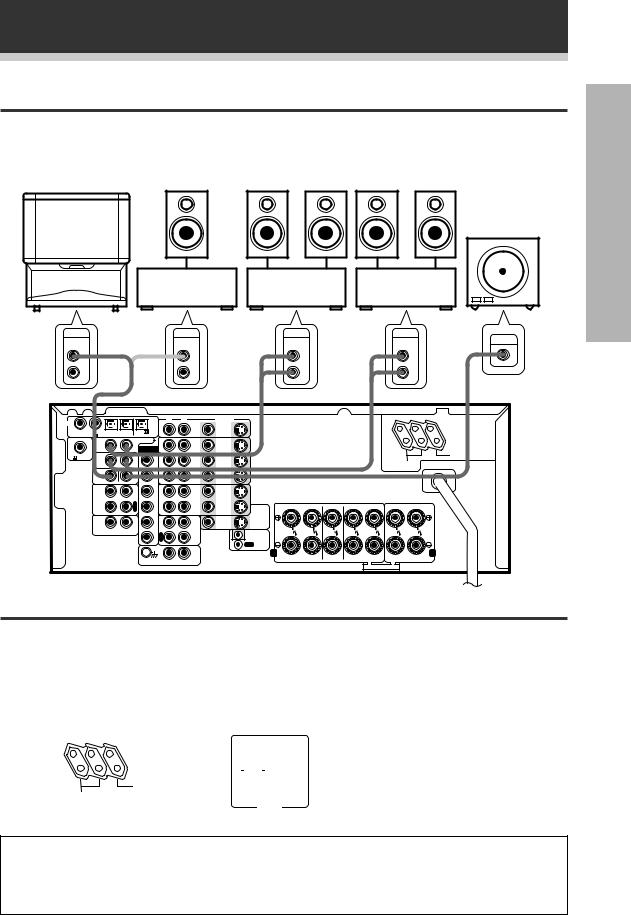
Connecting Your Equipment
Connecting Additional Amplifiers
Although the VSX-D938TX/D908TX/D908TX-G has more than sufficient power for any home use, it is possible to add additional amplifiers to your system. If you want to use separate amplifiers to power your speakers, make the connections shown below.
When connecting your equipment always make sure the power is turned off and the power cord is disconnected from the wall outlet for all the eqiuipment.
|
PIONEER |
|
|
|
|
Powered |
projection TV |
|
|
|
|
||
|
|
|
|
sub woofer |
||
|
(for center |
|
|
|
|
|
|
|
|
|
|
|
|
|
channel) |
|
|
|
|
|
|
|
|
Amplifier |
Amplifier |
Amplifier |
|
|
|
|
(for center |
(for surround |
(for front |
|
|
|
|
channel) |
channels) |
channels) |
|
L-Audio |
AUDIO |
(or) |
AUDIO |
AUDIO |
AUDIO |
|
(MONO) |
IN |
IN |
IN |
IN |
INPUT |
|
|
L |
|
L |
L |
L |
|
|
R |
|
R |
R |
R |
|
VSX-D938TX (Singaporean model)
DIGITAL |
|
|
|
|
|
R |
L |
VIDEO |
|
|
|
|
|
|
|
AC OUTLETS |
|
|
|
|
|
|
DVD |
S |
|
|
|
|
|
|
|
CAUTION: |
|
|
|
|
|
|
|
|
|
|
|
|
|
|
|
|||
1 |
2 |
3 |
4 |
PCM/ /DTS |
|
/LD |
|
|
|
|
|
|
|
|||
|
IN |
IN |
|
|
|
|
|
|
|
DO NOT |
||||||
PCM/ |
/DTS IN/MPEG IN |
/MPEG OUT |
|
|
|
|
|
|
|
|
|
|
CONNECT |
|||
|
S |
|
|
S |
PREOUT |
|
TV/ |
S |
S2 |
|
|
|
|
|
|
TV SET OR |
|
|
|
|
|
|
|
|
|
|
|
MONITOR. |
|||||
|
R |
|
|
L |
EXTERNAL |
|
SAT |
IN |
IN |
|
|
|
|
|
|
|
|
|
|
|
|
DECODER |
|
IN |
|
|
|
|
|
|
|
|
UNSWITCHED |
|
|
|
|
|
IN |
|
|
|
|
|
|
|
|
|
|
|
RF IN |
F |
|
|
F |
F |
|
|
S |
|
|
|
|
|
|
|
100W MAX |
|
|
|
IN |
|
|
|
|
|
|
SWITCHED |
|
|||||
|
R |
|
|
L |
L |
|
|
IN |
|
|
|
|
|
|
|
|
|
|
|
|
|
|
|
VCR1 |
|
|
|
|
|
|
|
TOTAL 100W MAX |
|
|
|
|
|
|
|
|
S |
|
|
|
|
|
|
|
|
|
|
C |
|
|
S |
F |
|
OUT |
|
|
|
|
|
|
|
|
|
|
|
|
W |
R |
|
OUT |
|
|
|
|
|
|
|
|
||
|
|
|
|
|
|
|
|
|
|
|
|
|
|
|||
|
|
|
|
P |
S |
|
|
S |
|
|
|
|
|
|
|
|
|
|
|
|
L |
|
IN |
|
|
|
|
|
|
|
|
||
|
|
|
|
A |
L |
|
|
IN |
|
|
|
|
|
|
|
|
|
TAPE2 |
|
|
Y |
|
|
|
|
|
|
|
|
|
|
|
|
|
MONITOR |
|
|
|
|
VCR2 |
|
|
|
|
|
|
|
|
|
|
|
|
|
|
R |
S |
|
|
S |
|
FR |
FL |
C |
SR |
SL |
R |
L |
|
|
|
|
E |
|
OUT |
TO |
|||||||||
|
|
|
|
C |
R |
|
|
OUT |
MONITOR |
|
|
|
|
|
|
|
|
|
|
|
|
|
|
|
|
TV |
|
|
|
|
|
|
|
|
|
|
|
I |
|
P |
|
|
S |
|
|
|
|
|
|
|
|
CD |
|
|
C |
L |
|
VIDEO |
|
|
|
|
|
|
|
||
|
|
|
|
N |
|
A |
MD/ |
OUT |
OUT |
|
|
|
|
|
|
|
|
|
R |
L |
|
|
Y |
|
|
|
|
|
|
|
|
|
|
|
|
|
S |
R |
TAPE1 |
|
IN |
|
|
|
|
|
|
|
||
|
|
|
|
|
W |
E |
|
|
CONTROL |
|
|
|
|
|
|
|
|
|
|
|
|
C |
|
|
|
|
|
|
|
|
|
||
|
|
|
|
|
|
|
|
|
OUT |
|
|
|
|
|
|
|
|
|
|
|
|
|
|
IN |
|
|
A |
FRONT |
CENTER |
SURROUND |
FRONT |
B |
|
|
|
|
|
|
|
|
PHONO |
|
|
SPEAKERS |
SPEAKERS |
SPEAKERS |
SPEAKERS |
|||
|
|
|
|
|
|
|
|
|
|
|
|
|
|
|
|
|
|
|
|
|
|
|
|
|
|
|
|
|
|
|
SEE INSTRUCTION MANUAL |
|
|
Power Connections (AC OUTLETS)
[SWITCHED TOTAL 100 W MAX]
Power supplied through these outlets is turned on and off by the receiver’s POWER switch. Total electrical power consumption of connected equipment should not exceed 100 W.
[UNSWITCHED 100 W MAX]
Power flows continually to this outlet, regardless of whether the receiver is switched ON or OFF. Electrical power consumption of the connected equipment should not exceed 100 W.
|
|
|
|
|
|
|
|
|
|
|
|
|
|
|
|
|
|
|
|
|
|
|
|
|
SWITCHED |
|
UNSWITCHED |
||||
|
|
||||||
TOTAL 100W MAX |
|
100W MAX |
|||||
UNSWITCHED 100W MAX
SWITCHED
TOTAL 100W MAX
|
AC OUTLETS |
Others |
Taiwanese model only |
CAUTION!
•To avoid overheating, fire risk, and possible malfunction do not connect high-wattage appliances such as heaters, irons, monitors, or TV sets to the AC OUTLETS.
•Remove the power plug from the wall socket to disconnect this unit from the AC power source when not in regular use, for example, when on vacation.
PREPARATION
17
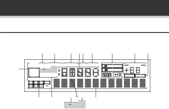
Displays and Controls
Display
All the display information is explained and/or referenced here.
|
|
|
2 |
|
3 |
|
4 56 |
7 |
8 |
9 |
0 |
||
|
SIGNAL ATT |
LOUDNESS |
MIDNIGHT |
DSP |
STEREO |
PRO LOGIC |
VOLUME |
|
|||||
1 |
SELECT OVER |
H.P |
|
|
|
|
|
|
|
||||
ANALOG SP |
AB |
|
|
|
|
|
DIGITAL |
|
dB |
|
|||
|
DIGITAL |
MONO STEREO |
|
|
|
|
|
|
|
||||
|
AC-3RF |
|
|
|
|
|
MPEG |
TAPE 2 |
|
||||
|
AUTO |
TUNED AMFM |
|
|
|
|
|
|
|||||
|
AC-3DTS MPEG |
|
|
|
|
|
|
|
|
|
|||
|
L |
C |
R |
LFE |
|
|
|
|
|
|
|
|
|
|
LS |
S |
RS |
|
|
|
|
|
|
|
|
|
|
|
|
- |
|
= |
|
! |
@ |
~ |
|
|
|
|
|
|
|
|
|
|
H.P |
|
|
|
|
||||
|
|
|
|
|
|
SP |
AB |
|
|
|
|
|
|
|
|
|
|
|
|
|
|
|
|
|
|
||
1 SIGNAL SELECT indicators
Light to indicate the type of input signal assigned for the current component (see “Front Panel”, % (VSX-D938TX), $ (VSX-D908TX/D908TX-G), SIGNAL SELECT).
ANALOG : Lights when an analog signal is selected.
DIGITAL : Lights when a digital audio signal is selected (DVD/LD, CD, MD/TAPE1, TV/SAT, VCR 1, VCR 2).
AC-3 RF: Lights when an AC-3 RF signal is selected (DVD/LD, TV/SAT, VCR 1, VCR 2). (VSXD938TX only)
AUTO: Lights when the receiver is set to select the input signal automatically. (DVD/LD, CD, MD/ TAPE 1, TV/SAT, VCR 1, VCR 2). (VSX-D938TX only)
AC-3 : Lights when a source with Dolby Digital signals is played.
DTS : Lights when a source with DTS audio signals is played.
MPEG: Blinks when the MPEG mode is selected, and lights when a source with MPEG audio signals is played. (VSX-D938TX only)
2 Analog level indicators
OVER : If “ANALOG” is selected in SIGNAL SELECT, this indicator lights to show that an excessively strong signal is being processed.
When this occurs, press INPUT ATT on the front panel to attenuate (lower) the signal. Also, when “DIGITAL” is selected in SIGNAL SELECT, this indicator lights to show that a source containing an excessive amount of information is being processed. If this occurs, see p. 41.
ATT : Lights when INPUT ATT is used to reduce the level of the input signal (available in ANALOG mode only).
3 LOUDNESS indicator (See p.48)
Lights when the LOUDNESS mode is on.
4 MIDNIGHT indicator (See p.46)
Lights when the MIDNIGHT LISTENING mode is on.
5 Radio Frequency/Function indicator
Displays the function or the frequency of the current radio station.
6 DSP indicator (See p.40-41)
Light when a DSP or Advanced Theater mode is selected.
7 STEREO indicator (See p.40-41)
Lights when a STEREO mode is selected.
8 2Surround/dts mode indicators
2DIGITAL : When the 2Surround/dts mode on the receiver is on, this indicator lights to
indicate playback of a Dolby Digital signal. However, 2PRO LOGIC lights during 2 channel playback of Dolby Digital.
2PRO LOGIC : When the 2Surround/dts mode on the receiver is on, this indicator lights during 2 channel playback. ( Both B or A+B speaker systems turn off automatically when headphones are plugged in.)
DTS : Lights when DTS signals are input. MPEG: Lights when MPEG signals are input. (Dolby/DTS/MPEG mode is ON). (VSX-D938TX only)
9 MASTER VOLUME indication
Displays current level of master volume.
0 TAPE 2 indicator
Lights when the TAPE 2 monitor is on.
18

- Program Format indicator
When a Dolby Digital or DTS signal is input, he following indicators light to show the channels being played back.
L : Left front*1*2, C : Center*1, R : Right front*1*2, LS : Left surround*1, S : Surround (mono)*2,
RS : Right surround*1
*1: Indicates 5.1ch Dolby Digital or DTS playback. *2: Indicates Dolby Pro Logic playback.
= Tuner indicators
MONO : Lights when the tuner is set to receive FM broadcasts and when selected MPX mode. STEREO : Lights when a FM stereo broadcast is received in the auto stereo mode.
TUNED : Lights when a broadcast is received. AM/FM : Light to indicate the current band (FM or AM).
~ Character display
Displays sound modes, general information, etc.
! Speaker indicators
Light to indicate the current speaker system (see “Front Panel”, ¡ (VSX-D938TX), + (VSX- D908TX/D908TX-G), SPEAKERS (A/B)).
SP # A : Lights when speaker system A is selected.
SP # B : Lights when speaker system B is selected.
SP # AB : Lights when speaker systems A and B are both selected.
@ H.P (headphones) indicator
Lights when headphones are connected to the PHONES jack (speakers A and B turn off automatically).
# LFE indicator
LFE (Low Frequency Effects) indicator lights to indicate that the program source contains an LFE channel. The indicator under the LFE lights during actual playback of the LFE signals (LFE signals are not present in all parts of the soundtrack).
Displays and Controls
PREPARATION
19
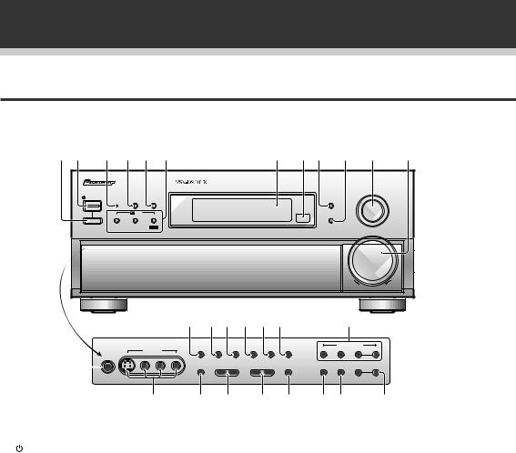
Displays and Controls
Front Panel (VSX-D938TX)
All the controls on the front panel are explained and/or referenced here. To open the front panel, push gently on the lower third of the panel.
1 2 3 4 5 6 |
7 8 9 0 - = |
|||
|
|
|
|
VSX-D938TX |
AUDIO/VIDEO MULTI-CHANNEL RECEIVER |
DigitalSignalProcessor |
|
||
STANDBY/ON |
DSP |
|
TAPE 2 |
INPUT |
STANDBY |
STEREO |
MONITOR |
SELECTOR |
|
MODE |
|
|||
|
/DTS |
|
FL |
|
THX CINEMA ADVANCED STANDARD |
DIMMER |
|
||
|
|
MPEG |
|
|
|
|
|
|
MASTER |
|
|
|
|
VOLUME |
|
|
|
DOWN |
UP |
|
|
|
|
~ !@ # $ % |
|
^ |
|
||||
5-CHANNEL EQUAL POWER OUTPUT |
EXTERNAL |
|
|
DIGITAL |
SIGNAL |
|
TUNER CONTROL |
||||
|
VIDEO INPUT |
|
DECODER IN DIRECT LOUDNESS MIDNIGHT |
NR |
SELECT |
CLASS |
FM/AM |
– TUNING + |
|||
|
|
|
|
|
|
|
|
|
|
||
S-VIDEO |
VIDEO |
L |
AUDIO |
R |
|
|
|
|
|
|
|
PHONES |
|
|
|
|
|
|
|
|
|
|
|
£ |
|
|
|
SPEAKERS |
– BASS + |
– TREBLE + |
INPUT ATT |
MPX |
MEMORY |
– STATION + |
|
™ ¡ + |
_ ) ( * & |
1 Main Power Switch (— OFF, _ ON) |
7 Display (See page 18) |
2 STANDBY/ON button |
8 Remote sensor |
Press to switch the receiver ON or into STANDBY mode.
Point the remote control toward the remote sensor to operate the receiver.
3 STANDBY indicator
Lights when the receiver is in STANDBY mode. (Please note that this receiver consumes a small amount of power (1.0 W) during the standby mode.)
4 DSP MODE button (See p.40-41)
Press repeatedly to select a DSP sound mode. (HALL 1, HALL 2, JAZZ, DANCE, THEATER 1, or THEATER 2). Use these modes to produce surround sound from standard (two channel) stereo sources and create different listening environments.
5 STEREO button (See p.40-41)
Press to select the STEREO sound mode. In this mode, sound comes from the front (left and right) speakers only.
62/DTS buttons (See p. 39, 41 and 76-
78)
THX CINEMA: Press to select the HOME THX CINEMA sound mode when listening to Dolby Digital, Dolby Pro Logic or DTS a variety of other sources.
ADVANCED THEATER : Press to select one of the four Advanced Theater modes. STANDARD (MPEG) : Press to select the STANDARD/MPEG mode.
9 TAPE 2 MONITOR button (See p.66)
Selects the tape deck (MD recorder, etc.) connected to the TAPE 2 MOINTOR inputs/ outputs. Allows monitoring of a recording as it is being made.
0 FL DIMMER button (See p.49)
Use to adjust the brightness of the main display.
- INPUT SELECTOR dial
Turn to select a source component. The source indicators show the current component: DVD/LD : DVD player or Laser Disc player. TV/SAT : TV tuner or satellite tuner.
CD : Compact Disc player.
MD/TAPE 1 : Tape deck or Mini Disc recorder connected to MD/TAPE 1 inputs/outputs. TUNER : The built-in tuner.
PHONO : Turntable.
VIDEO : Video camera (etc.) connected to the VIDEO INPUT on the front panel.
VCR 1 : Video cassette recorder connected to VCR 1 inputs.
VCR 2 : Video cassette recorder or other component connected to VCR 2 inputs.
20
= MASTER VOLUME
Adjusts the overall receiver volume.
~ EXTERNAL DECODER IN (See p.47)
Use to hook up an external component that can decode other types of signals and input them into the VSX-D938TX.
! DIRECT button
Switches DIRECT playback on or off. Use to bypass the tone controls and channel level for the most accurate reproduction of a program source. It will automatically put the receiver in STEREO mode for the function being used for DIRECT playback.
@ LOUDNESS button (See p.48)
Switches the LOUDNESS mode on or off.
# MIDNIGHT button (See p.46)
Switches the MIDNIGHT LISTENING mode on or off.
$ DIGITAL NR button (See p.45)
Switches the DIGITAL NR on or off (STEREO mode only).
% SIGNAL SELECT button (See p.42)
Use to select the signal from the digital components.
SIGNAL SELECT repeatedly to select one of the following:
ANALOG : To select an analog signal. DIGITAL : To select a optical or electrical digital signal.
AC-3 RF: To select an AC-3 RF signal. AUTO: This is the default. If there are both analog and digital input signals, the receiver automatically selects the digital signal.
^ TUNER CONTROL button (See p.50-53)
CLASS : Press repeatedly to switch the preset station classes.
FM/AM : Press to select the AM or FM band. TUNING –/+ : Use to manually tune to radio stations.
& STATION –/+ buttons (See p.52-53)
Use to choose programmed radio stations.
* MEMORY button (See p.52)
Press to start the memorization of a preset station.
( MPX button (See p.50)
Press to switch between auto stereo and MONO reception of FM broadcasts. When the broadcast signal is weak, selecting MONO will improve the sound quality.
Displays and Controls
) INPUT ATT button
Use to lower the input level of an analog signal that is too powerful, thus causing the receiver to distort (the overload indicator will light furiously).
_ TREBLE (–/+) buttons (See p.48)
Use to adjust the high frequencies.
+ BASS (–/+) buttons (See p.48)
Use to adjust low frequencies.
¡ SPEAKERS (A/B) buttons
A is the primary setting. It plays all speakers hooked up to the A system. A and B setting only plays the front speakers of both the A and B systems and the sub-woofer, multi channel sources will be down-mixed to these speakers so no sound will be lost. B setting only plays the front speakers connected to the B system and multi channel sources will be down-mixed to these two speakers.
 A
A  B
B  A+B
A+B  OFF
OFF
™ VIDEO INPUT jacks (See p.9)
S-VIDEO : Video input for connecting a video camera (etc.), that has an S-Video out.
VIDEO / AUDIO (L/R) : Video input for connecting a video camera, etc. that has standard video/audio outputs.
£ PHONES jack
Connect headphones for private listening (no sound will be heard through the speakers).
PREPARATION
21
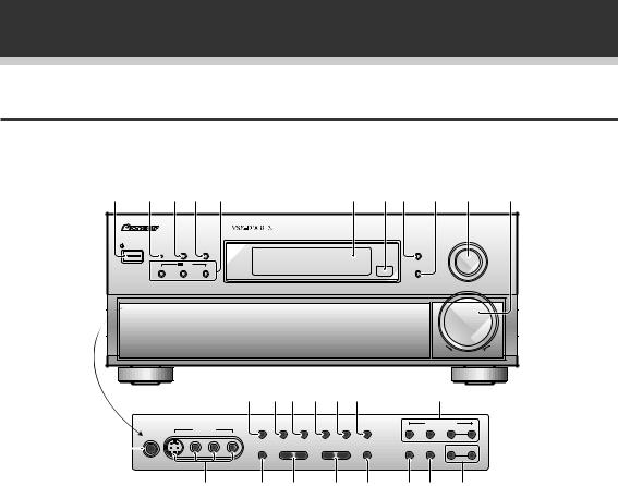
Displays and Controls
Front Panel (VSX-D908TX/D908TX-G)
All the controls on the front panel are explained and/or referenced here. To open the front panel, push gently on the lower third of the panel.
1 |
2 3 4 5 |
6 7 8 9 |
0 |
- |
||
|
AUDIO/VIDEO MULTI-CHANNEL RECEIVER |
DigitalSignalProcessor |
|
|
||
|
|
|
|
|
|
INPUT |
|
|
|
|
|
|
SELECTOR |
|
STANDBY/ON |
DSP |
|
TAPE 2 |
|
|
|
STANDBY |
MODE |
STEREO |
MONITOR |
|
|
|
|
/DTS |
|
FL |
|
|
|
THX CINEMA |
ADVANCED |
STANDARD |
DIMMER |
|
|
|
|
|
|
|
|
MASTER |
|
|
|
|
|
|
VOLUME |
|
|
|
|
DOWN |
|
UP |
|
|
|
|
= ~! @ # $ |
|
% |
|
|||
5-CHANNEL EQUAL POWER OUTPUT |
EXTERNAL |
|
DIGITAL |
SIGNAL |
|
TUNER CONTROL |
||||
|
VIDEO INPUT |
|
DECODER IN DIRECT |
LOUDNESS MIDNIGHT |
NR |
SELECT |
CLASS |
FM/AM |
– TUNING + |
|
|
|
|
|
|
|
|
|
|
||
S-VIDEO |
VIDEO |
L |
AUDIO |
R |
|
|
|
|
|
|
PHONES |
|
|
|
|
|
|
|
|
|
|
™ |
SPEAKERS – BASS + |
– TREBLE + INPUT ATT |
MPX MEMORY – STATION + |
|
¡ + _ |
) ( |
* & ^ |
1  STANDBY/ON button
Press to switch the receiver ON or into STANDBY mode.
2 STANDBY indicator
Lights when the receiver is in STANDBY mode. (Please note that this receiver consumes a small amount of power (1.0 W) during the standby mode.)
3 DSP MODE button (See p.40-41)
Press repeatedly to select a DSP sound mode. (HALL 1, HALL 2, JAZZ, DANCE, THEATER 1, or THEATER 2). Use these modes to produce surround sound from standard (two channel) stereo sources and create different listening environments.
4 STEREO button (See p.40-41)
Press to select the STEREO sound mode. In this mode, sound comes from the front (left and right) speakers only.
52/DTS buttons (See p. 39, 41 and 76-
78)
THX CINEMA: Press to select the HOME THX CINEMA sound mode when listening to Dolby Digital, Dolby Pro Logic or DTS a variety of other sources.
ADVANCED THEATER : Press to select one of the four Advanced Theater modes. STANDARD : Press for pure decoding of multi
channel sources.
22
6 Display (See p.18)
7 Remote sensor
Point the remote control toward the remote sensor to operate the receiver.
8 TAPE 2 MONITOR button (See p.66)
Selects the tape deck (MD recorder, etc.) connected to the TAPE 2 MOINTOR inputs/ outputs. Allows monitoring of a recording as it is being made.
9 FL DIMMER button (See p.49)
Use to adjust the brightness of the main display.
0 INPUT SELECTOR dial
Turn to select a source component. The source indicators show the current component: DVD/LD : DVD player or Laser Disc player. TV/SAT : TV tuner or satellite tuner.
CD : Compact Disc player.
MD/TAPE 1 : Tape deck or Mini Disc recorder connected to MD/TAPE 1 inputs/outputs. TUNER : The built-in tuner.
PHONO : Turntable.
VIDEO : Video camera (etc.) connected to the VIDEO INPUT on the front panel.
VCR 1 : Video cassette recorder connected to VCR 1 inputs.
VCR 2 : Video cassette recorder or other component connected to VCR 2 inputs.
- MASTER VOLUME
Adjusts the overall receiver volume.

=EXTERNAL DECODER IN button (See p.47)
Use to hook up an external component that can decode other types of signals and input them into the VSX-D908TX/D908TX-G.
~ DIRECT button
Switches direct playback on or off. Use to bypass the tone controls and channel level for the most accurate reproduction of a program source. It will automatically put the receiver in STEREO mode for that function being used for DIRECT playback.
! LOUDNESS button (See p.48)
Switches the LOUDNESS mode on or off.
@ MIDNIGHT MODE button (See p.46)
Switches the MIDNIGHT LISTENING mode on or off.
# DIGITAL NR button (See p.45)
Switches the DIGITAL NR on or off (STEREO mode only).
$ SIGNAL SELECT button (See p.42)
Use to select the signal from the digital components.
SIGNAL SELECT repeatedly to select one of the following:
ANALOG : To select an analog signal. DIGITAL : To select a optical or electrical digital signal.
% TUNER CONTROL button (See p.50-53)
CLASS : Press repeatedly to switch the preset station classes.
FM/AM : Press to select the AM or FM band. TUNING –/+ : Use to manually tune to radio stations.
^ STATION –/+ buttons (See p.52-53)
Use to choose programmed radio stations.
& MEMORY button (See p.52)
Press to start the memorization of a preset station.
* MPX button (See p.50)
Press to switch between auto stereo and MONO reception of FM broadcasts. When the broadcast signal is weak, selecting MONO will improve the sound quality.
( INPUT ATT button
Use to lower the input level of an analog signal that is too powerful, thus causing the receiver to distort (the overload indicator will light furiously).
) TREBLE (–/+) buttons (See p.48)
Use to adjust the high frequencies.
Displays and Controls
_ BASS (–/+) buttons (See p.48)
Use to adjust low frequencies.
+ SPEAKERS (A/B) buttons
A is the primary setting. It plays all speakers hooked up to the A system. A and B setting only plays the front speakers of both the A and B systems and the sub-woofer, multi channel sources will be down-mixed to these speakers so no sound will be lost. B setting only plays the front speakers connected to the B system and multi channel sources will be down-mixed to these two speakers.
 A
A  B
B  A+B
A+B  OFF
OFF
¡ VIDEO INPUT jacks (See p.9)
S-VIDEO : Video input for connecting a video camera (etc.), that has an S-Video out.
VIDEO / AUDIO (L/R) : Video input for connecting a video camera, etc. that has standard video/audio outputs.
™ PHONES jack
Connect headphones for private listening (no sound will be heard through the speakers)
PREPARATION
23
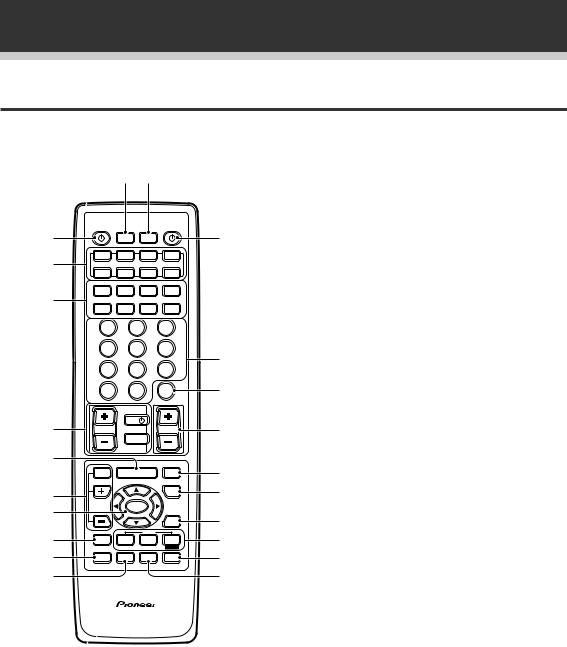
Displays and Controls
Remote Control
These pages describe the buttons on the remote control used to operate the receiver.
- =
1  SOURCE button (See p.58-65)
Use to turn on the power of your other components after you have recalled or taught the signals to this remote control.
Î
1 |
S0URCE |
RECEIVER |
MULTI |
SYSTEM |
|
|
OPERATION |
OFF |
2 |
DVD/LD |
TV/SAT |
VCR1 |
VCR2 |
|
MULTI CONTROL |
|
||
|
CD |
MD/ |
TUNER |
TV CONT |
|
TAPE1 |
|||
|
CLASS |
MPX |
BAND |
DIRECT ACCESS |
3 |
¶ |
7 |
3 |
8 |
- TUNING + |
- STATION + |
|||
|
1 |
¡ |
4 ¢ |
|
- CHANNEL +
1 2 3
4 5 6
7 8 9
+10 |
0 |
DISC |
RF ATT |
DISPLAY |
4 |
|
TV |
|
TV VOL |
TV CONTROL |
VOLUME |
|
|
|
TV FUNC |
|
5 |
|
|
|
|
EFFECT |
MENU |
|
|
/CH SEL |
||
6 |
|
|
|
7 |
|
ENTER |
|
|
|
|
|
8 |
|
|
2/dts |
SYSTEM |
THX |
ADVANCED |
|
SETUP |
|||
9 |
REMOTE |
MIDNIGHT |
DSP |
SETUP |
|||
0 |
|
|
|
MUTE |
FUNCTION |
SIGNAL |
SELECT |
STANDARD
MPEG
STEREO |
DIGITAL NR
AV PREPROGRAMMED AND LEARNING
REMOTE CONTROL UNIT
VSX-D938TX
2 MULTI CONTROL buttons
Use these to select a source and the corresponding remote operation mode.
~For example, pressing TUNER selects the built in tuner and sets the remote operation to the tuner functions.
3 Component Control buttons
Use to control specific components, like a CD player or DVD player, after you have programmed the remote control to do these operations (see p.58-65) and the remote is put in that operation
mode.
!
4TV CONTROL buttons
@The following buttons are used to control the TV only and can be used no matter what function the remote control is set to.
#TV  : Press to turn the power of the TV on/off. TV FUNC : Press TV FUNC to select the TV for remote control operation.
$ |
TV VOL +/– : Press to control the volume of the |
|
TV. |
||
|
||
% |
5 MENU button |
|
|
||
^ |
Use to get the various menus for this unit onto |
|
your TV or DTV screen. |
||
& |
||
|
*6 EFFECT/CH SEL +/– buttons (See p.41)
EFFECT : Use these buttons to increase or
( decrease the amount of effect applied in a DSP or Advanced Theater mode. When the amount of effect is increased in a DSP/Advanced Theater mode the characteristics of that mode become stronger and more noticeable. The scale ranges from 10-90 with 70 as the default setting. First turn on the DSP/Advanced Theater you want (by pressing the DSP/Advanced Theater button until you get the mode) and then increase or decrease the amount of effect.
CH SEL : You may want to adjust the channels when listening to some sound sources. Use this button to select the channel you want to adjust. +/– : Use these buttons to select the amount of effect in a sound mode and to adjust the channel level when making surround sound settings.
7 5/ /2/3/ENTER buttons
Use to operate the on-screen menu on your TV screen and enter commands when setting up surround sound, speakers levels & settings, and other set up features see p.27-37). Specific use of these buttons is described in conjunction with the operations they perform. For more information, see each individual section.
24

8 SYSTEM SETUP button
Use to set up the speaker and sound systems. For more information, see “Surround Sound Setup” on p. 26.
9 REMOTE SETUP button.
Use to customize the remote control functions and the remote control itself. (See “Setting Up the Remote Control to Control Other Components” on p.54, “Multi Operation” on p. 69.)
To access the EXTERNAL DECODER option, press the REMOTE SETUP button and the SIGNAL SELECT button simultaneously.
0 MIDNIGHT button (See p. 46)
Switches the MIDNIGHT LISTENING mode on or off.
- MULTI OPERATION button
Use this button to start the MULTI OPERATION mode. See p. 69 for how to program and use the MULTI OPERATION mode.
= SYSTEM OFF button
This button turns off components in two ways. First, when pressed it will turn off all PIONEER components. Secondly, any component that has programmed into the MULTI OPERATIONS settings will also be turned off. (see p.69).
For example : If you programmed power off in the SYSTEM OFF settings for your TV and VCR, pressing the SYSTEM OFF button will turn off these components even if they are not PIONEER products.
~  RECEIVER button
Press to turn power of the receiver on or to STANDBY (off).
! Number buttons
These buttons can perform a variety of different functions depending on the remote operation mode. They are most useful for CD and tuner operations.
@ DISC/DISPLAY button
These buttons can perform a variety of different functions depending on the remote operation mode.
# MASTER VOLUME button
Use to raise or lower the volume of the receiver.
$ MUTE button
Press to mute or restore the volume.
% FUNCTION button
Press to select a source. The button will cycle through all the possible sources.
Displays and Controls
^ SIGNAL SELECT button
Press SIGNAL SELECT repeatedly to select one of the following:
ANALOG : To select an analog signal. DIGITAL : To select a digital signal (DVD/LD, TV/SAT, CD, MD/TAPE 1, VCR 1, VCR 2). AC-3 RF: To select an AC-3 RF signal (DVD/LD, TV/SAT, VCR 1, VCR 2). (VSX-D938TX only) AUTO: This is the default. If there are both analog and digital input signal, the receiver automatically selects the best possible signal.
Press the SIGNAL SELECT and REMOTE SETUP buttons simultaneously to switch from the SIGNAL SELECT operation to EXTERNAL DECODER operation.
Then press the button to get the EXTERNAL DECODER function. To get back to the SIGNAL SELECT control, press the REMOTE SETUP button and the SIGNAL SELECT button simultaneously once again. (VSX-D938TX only)
&2/dts/MPEG (VSX-D938TX only) buttons (See p.41)
Press these buttons to put the receiver in the selected sound mode. For more information on the modes .
* STEREO/DIGITAL NR button
STEREO : Press this button to put the receiver into stereo mode when it is in a different sound mode. For more information on the sound modes, see p.41.
DIGITAL NR : Switches the DIGITAL NR on or off (see p.44).
( DSP button (See p.41)
Press repeatedly to select a DSP sound mode.
PREPARATION
25
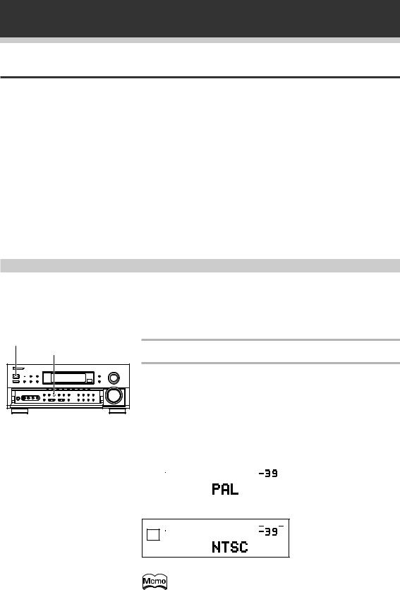
Surround Sound Set Up
On Screen Display
There are a number of possible ways to hook up the receiver to your video components like a DVD player and hook up to your receiver to your TV, but some of them will not allow you to use the on-screen display of this unit. To avoid this one simply needs to follow two rules.
1Always use the same type of video cords to hook up your video components to the receiver as you use to hook up the receiver and your TV. For example, if you use composite video cords to hook up your DVD and the receiver, use composite video cords to hook up the receiver to your TV. If you use S video cords to hook up your DVD and the receiver, use S video cords to hook up the receiver to your TV.
2Always make sure your TV is set to the appropriate input channel on your TV (for example, video 1). Your TV may have a number of input channels and if you do not select the proper one you will not be able to use this receiver’s on-screen display. If you are unsure how to choose an input channel for your TV, refer to the manual which came with your TV.
You might, for example, use both composite and S video cords to hook up your video component with this receiver and then use composite video cords to hook up this receiver to your TV. This arrangement would still NOT let you see the on screen displays from this receiver on your TV. The best idea is just to use one type of video cord for all your video component and TV hook ups.
Switching video system between PAL and NTSC
This receiver is able to use two types of video systems for its OSD (on screen display) and you need to set the receiver to the type of video system you have, either PAL or NTSC. If you do not match the system on the receiver with your home system no OSD will appear on your TV. People with multi-system TVs, don’t need to worry about changing the setting. If necessary, follow the instructions below to switch the type of video system.
wSTANDBY/ON |
LOUDNESS |
VSX-D938TX |
1Put the receiver in STANDBY mode.
2While holding down the LOUDNESS button press the STANDBY/ON button. The video system type, either ”PAL“ on ”NTSC,“ appears in the display. It will be shown for about seven seconds and then the receiver reverts to normal operating mode.
Be careful to press the LOUDNESS button and NOT the DIRECT button, which will accidentally clear all your speaker settings (see warning p.29-30).
|
SIGNAL |
|
|
VOLUME |
|
|
when a PAL system is |
||
|
SELECT |
|
|
|
|
|
selected |
||
|
|
|
|
|
|
dB |
|||
|
DIGITAL |
|
|
||||||
|
|
|
|
SP A |
|
||||
|
|
|
|
|
|
|
|
|
|
|
|
|
|
|
|
|
|
|
|
SIGNAL
SELECT
SP A
DIGITAL
VOLUME
dB
when a NTSC system is selected
When using the PAL setting the OSD does not get displayed in color.
26
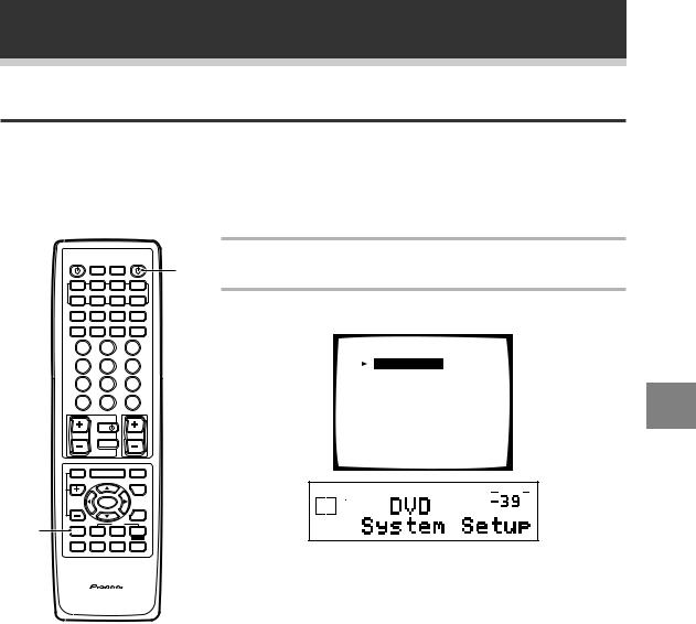
Surround Sound Set Up
Setting Up for Surround Sound
To ensure the best possible surround sound, be sure to complete the following set up operations. This is particularly important when using the DTS, 2(Dolby) Surround sound and MPEG (VSX-D938TX only) modes. You only need to make these settings once (unless you change the placement of your current speaker system or add new speakers, etc.). These set up operations use your TV to display the settings and choices so be sure your TV and receiver are properly hooked up.
|
|
|
Î |
1 |
1 Turn on the receiver and your TV. |
|
|
|
|
|
|
|
|
||
S0URCE |
|
|
RECEIVER |
Make sure your TV is set to the receiver. |
|
||
|
MULTI |
SYSTEM |
|
|
|
||
|
OPERATION |
OFF |
|
|
|
|
|
DVD/LD |
TV/SAT |
VCR1 |
VCR2 |
|
|
|
|
|
MULTI CONTROL |
|
|
2 Press SYSTEM SETUP button. |
|
||
CLASS |
MPX |
BAND |
DIRECT ACCESS |
|
|
||
CD |
MD/ |
TUNER |
TV CONT |
|
|
|
|
TAPE1 |
|
|
|
|
|||
¶ |
7 |
3 |
8 |
|
The SYSTEM SETUP MENU appears on your TV screen. |
||
- TUNING + |
- STATION + |
|
|||||
1 |
¡ |
4 ¢ |
|
|
|
|
|
|
|
- CHANNEL + |
|
|
System Setup |
|
|
1 |
2 |
|
3 |
|
|
|
|
4 |
5 |
|
6 |
|
|
[Speaker Setting] |
|
7 |
8 |
|
9 |
|
|
[Channel Delay] |
|
|
|
|
[Channel Level] |
|
|||
|
|
|
|
|
|
|
|
+10 |
0 |
|
DISC |
|
|
[Crossover Network] |
|
RF ATT |
|
|
DISPLAY |
|
|
[Bass Peak Level Manager] |
|
|
|
|
|
|
|
|
|
|
TV |
|
|
|
|
[D-Range Control] |
|
TV VOL |
TV CONTROL |
|
VOLUME |
|
|
[Digital-In Select] |
|
|
TV FUNC |
|
|
|
|
||
EFFECT |
MENU |
MUTE |
|
|
|
|
|
/CH SEL |
|
|
|
|
|||
|
|
|
FUNCTION |
|
SIGNAL |
STEREO |
|
|
|
|
|
|
VOLUME |
||
|
|
|
|
|
SELECT |
|
|
|
ENTER |
|
|
ANALOG SP A |
|
dB |
|
|
|
|
|
|
|||
|
|
|
|
|
|
|
|
2 |
|
|
|
SIGNAL |
AUTO |
|
|
|
SELECT |
|
|
|
|
2/dts |
|
|
|
SYSTEM |
THX |
ADVANCED |
STANDARD |
|
|
SETUP |
|
||||
|
|
|
MPEG |
|
REMOTE |
MIDNIGHT |
DSP |
STEREO |
SETUP |
DIGITAL NR
* You can escape from this screen at any time by pressing the SYSTEM SETUP button again. None of the settings you made will
be entered in this case.
AV PREPROGRAMMED AND LEARNING
REMOTE CONTROL UNIT
VSX-D938TX
SET UP
27
 Loading...