


 Loading...
AUDIO/VIDEO MULTI-CHANNEL RECEIVER
RECEPTEUR AUDIOVISUEL A
VOIES MULTI-CANAUX
RECEPTOR AUDIO-VIDEO MULTICANAL
VSX-820
Register your product on
http://www.pioneerelectronics.com (US) http://www.pioneerelectronics.ca (Canada)
• Protect your new investment
The details of your purchase will be on file for reference in the event of an insurance claim such as loss or theft.
•Receive free tips, updates and service bulletins on your new product
•Improve product development
Your input helps us continue to design products that meet your needs.
• Receive a free Pioneer newsletter
Registered customers can opt in to receive a monthly newsletter.
http://www.pioneerelectronics.com (US) http://www.pioneerelectronics.ca (Canada)
Operating Instructions Mode d’emploi
Manual de instrucciones
WARNING
This equipment is not waterproof. To prevent a fire or shock hazard, do not place any container filled with liquid near this equipment (such as a vase or flower pot) or expose it to dripping, splashing, rain or moisture.
D3-4-2-1-3_A1_En
WARNING
Before plugging in for the first time, read the following section carefully.
The voltage of the available power supply differs according to country or region. Be sure that the power supply voltage of the area where this unit will be used meets the required voltage (e.g., 230 V or 120 V) written on the rear panel.
D3-4-2-1-4*_A1_En
This product is for general household purposes. Any failure due to use for other than household purposes (such as long-term use for business purposes in a restaurant or use in a car or ship) and which requires repair will be charged for even during the warranty period.
K041_A1_En
IMPORTANT NOTICE
THE MODEL NUMBER AND SERIAL NUMBER OF THIS EQUIPMENT ARE ON THE REAR OR BOTTOM. RECORD THESE NUMBERS ON YOUR ENCLOSED WARRANTY CARD AND KEEP IN A SAFE PLACE FOR FUTURE REFERENCE.
D36-AP9-1_A1_En
This Class B digital apparatus complies with Canadian ICES-003.
D8-10-1-3_A1_En
If the AC plug of this unit does not match the AC outlet you want to use, the plug must be removed and appropriate one fitted. Replacement and mounting of an AC plug on the power supply cord of this unit should be performed only by qualified service personnel. If connected to an AC outlet, the cut-off plug can cause severe electrical shock. Make sure it is properly disposed of after removal.
The equipment should be disconnected by removing the mains plug from the wall socket when left unused for a long period of time (for example, when on vacation).
D3-4-2-2-1a_A1_En
WARNING: Handling the cord on this product or cords associated with accessories sold with the product may expose you to chemicals listed on proposition 65 known to the State of California and other governmental entities to cause cancer and birth defect or other reproductive harm.
Wash hands after handling.
D36-P5_B1_En
CAUTION
This product satisfies FCC regulations when shielded cables and connectors are used to connect the unit to other equipment. To prevent electromagnetic interference with electric appliances such as radios and televisions, use shielded cables and connectors for connections.
D8-10-3a_A1_En
Information to User
Alterations or modifications carried out without appropriate authorization may invalidate the user’s right to operate the equipment.
D8-10-2_A1_En
NOTE:
This equipment has been tested and found to comply with the limits for a Class B digital device, pursuant to Part 15 of the FCC Rules. These limits are designed to provide reasonable protection against harmful interference in a residential installation. This equipment generates, uses, and can radiate radio frequency energy and, if not installed and used in accordance with the instructions, may cause harmful interference to radio communications. However, there is no guarantee that interference will not occur in a particular installation. If this equipment does cause harmful interference to radio or television reception, which can be determined by turning the equipment off and on, the user is encouraged to try to correct the interference by one or more of the following measures:
—Reorient or relocate the receiving antenna.
—Increase the separation between the equipment and receiver.
—Connect the equipment into an outlet on a circuit different from that to which the receiver is connected.
—Consult the dealer or an experienced radio/TV technician for help.
D8-10-1-2_A1_En
FEDERAL COMMUNICATIONS COMMISSION DECLARATION OF CONFORMITY
This device complies with part 15 of the FCC Rules. Operation is subject to the following two conditions: (1) This device may not cause harmful interference, and (2) this device must accept any interference received, including interference that may cause undesired operation.
Product Name: AUDIO/VIDEO MULTI-CHANNEL RECEIVER Model Number: VSX-820
Responsible Party Name: PIONEER ELECTRONICS (USA) INC. SERVICE SUPPORT DIVISION
Address: 1925 E. DOMINGUEZ ST. LONG BEACH, CA 90810-1003, U.S.A. Phone: 1-800-421-1404
URL: http://www.pioneerelectronics.com
D8-10-4*_C1_En
IMPORTANT
CAUTION
RISK OF ELECTRIC SHOCK
DO NOT OPEN
The lightning flash with arrowhead symbol, within an equilateral triangle, is intended to alert the user to the presence of uninsulated “dangerous voltage” within the product’s enclosure that may be of sufficient magnitude to constitute a risk of electric shock to persons.
CAUTION:
TO PREVENT THE RISK OF ELECTRIC SHOCK, DO NOT REMOVE COVER (OR BACK). NO USER-SERVICEABLE PARTS INSIDE. REFER SERVICING TO QUALIFIED SERVICE PERSONNEL.
The exclamation point within an equilateral triangle is intended to alert the user to the presence of important operating and maintenance (servicing) instructions in the literature accompanying the appliance.
D3-4-2-1-1_A1_En
1)Read these instructions.
2)Keep these instructions.
3)Heed all warnings.
4)Follow all instructions.
5)Do not use this apparatus near water.
6)Clean only with dry cloth.
7)Do not block any ventilation openings. Install in accordance with the manufacturer’s instructions.
8)Do not install near any heat sources such as radiators, heat registers, stoves, or other apparatus (including amplifiers) that produce heat.
9)Do not defeat the safety purpose of the polarized or grounding-type plug. A polarized plug has two blades with one wider than the other. A grounding type plug has two blades and a third grounding prong. The wide blade or the third prong are provided for your safety. If the provided plug does not fit into your outlet, consult an electrician for replacement of the obsolete outlet.
10)Protect the power cord from being walked on or pinched particularly at plugs, convenience receptacles, and the point where they exit from the apparatus.
11)Only use attachments/accessories specified by the manufacturer.
12)Use only with the cart, stand, tripod, bracket, or table specified by the manufacturer, or sold with the apparatus. When a cart is used, use caution when moving the cart/apparatus combination to avoid injury from tip-over.
13)Unplug this apparatus during lightning storms or when unused for long periods of time.
14)Refer all servicing to qualified service personnel. Servicing is required when the apparatus has been damaged in any way, such as power-supply cord or plug is damaged, liquid has been spilled or objects have fallen into the apparatus, the apparatus has been exposed to rain or moisture, does not operate normally, or has been dropped.
D3-7-13-69_En
VENTILATION CAUTION
When installing this unit, make sure to leave space around the unit for ventilation to improve heat radiation (at least 40 cm at top, 10 cm at rear, and 20 cm at each side).
WARNING
Slots and openings in the cabinet are provided for ventilation to ensure reliable operation of the product, and to protect it from overheating. To prevent fire hazard, the openings should never be blocked or covered with items (such as newspapers, table-cloths, curtains) or by operating the equipment on thick carpet or a bed.
D3-4-2-1-7b*_A1_En
Operating Environment
Operating environment temperature and humidity: +5 °C to +35 °C (+41 °F to +95 °F); less than 85 %RH (cooling vents not blocked)
Do not install this unit in a poorly ventilated area, or in locations exposed to high humidity or direct sunlight (or strong artificial light)
WARNING
To prevent a fire hazard, do not place any naked flame sources (such as a lighted candle) on the equipment.
D3-4-2-1-7a_A1_En
CAUTION
The STANDBY/ON switch on this unit will not completely shut off all power from the AC outlet. Since the power cord serves as the main disconnect device for the unit, you will need to unplug it from the AC outlet to shut down all power. Therefore, make sure the unit has been installed so that the power cord can be easily unplugged from the AC outlet in case of an accident. To avoid fire hazard, the power cord should also be unplugged from the AC outlet when left unused for a long period of time (for example, when on vacation).
Caution
To prevent fire hazard, the Class 2 Wiring Cable should be used for connection with speaker, and should be routed away from hazards to avoid damage to the insulation of the cable.

Thank you for buying this Pioneer product. Please read through these operating instructions so you will know how to operate your model properly. After you have finished reading the instructions, put them away in a safe place for future reference.
Contents
01 Before you start |
|
04 Basic Setup |
|
Checking what’s in the box . . . . . . . . . . . . . . . |
7 |
Automatically setting up for surround |
|
Loading the batteries . . . . . . . . . . . . . . . . . . . |
7 |
sound (MCACC) . . . . . . . . . . . . . . . . . . . . . . |
29 |
Installing the receiver . . . . . . . . . . . . . . . . . . . |
7 |
Other problems when using the Auto |
|
Ventilation . . . . . . . . . . . . . . . . . . . . . . . . . . |
8 |
MCACC Setup. . . . . . . . . . . . . . . . . . . . . . . |
31 |
02 Controls and displays
Front panel . . . . . . . . . . . . . . . . . . . . . . . . . . . 9
Operating range of remote control . . . . . . . 10
Display . . . . . . . . . . . . . . . . . . . . . . . . . . . . . 11 Remote control . . . . . . . . . . . . . . . . . . . . . . . 13
03 Connecting your equipment
Placing the speakers. . . . . . . . . . . . . . . . . . . 16
Hints on the speaker placement. . . . . . . . . 17 Connecting the speakers . . . . . . . . . . . . . . . 18
Connect the surround back or front
height speakers . . . . . . . . . . . . . . . . . . . . . 19
Switching the speaker system . . . . . . . . . . 20 Making cable connections . . . . . . . . . . . . . . 20
HDMI cables . . . . . . . . . . . . . . . . . . . . . . . 20 About HDMI . . . . . . . . . . . . . . . . . . . . . . . . 21 Analog audio cables. . . . . . . . . . . . . . . . . . 21 Digital audio cables . . . . . . . . . . . . . . . . . . 21 Video cables . . . . . . . . . . . . . . . . . . . . . . . . 21
About video outputs connection . . . . . . . . . . 22 Connecting a TV and playback components . . . 23 Connecting using HDMI. . . . . . . . . . . . . . . 23
Connecting your component with no
HDMI terminal . . . . . . . . . . . . . . . . . . . . . . 24
Connecting a satellite receiver or other
digital set-top box . . . . . . . . . . . . . . . . . . . . . 25
Connecting an HDD/DVD recorder, VCR
and other video sources . . . . . . . . . . . . . . . . 25 Using the component video jacks . . . . . . . . . 26 Connecting other audio components . . . . . . 26
Connecting antennas . . . . . . . . . . . . . . . . . . 27
Using external antennas. . . . . . . . . . . . . . . 27 Connecting to the front panel video
terminal . . . . . . . . . . . . . . . . . . . . . . . . . . . . 28
Plugging in the receiver . . . . . . . . . . . . . . . . 28
05 Listening to your system
Basic playback . . . . . . . . . . . . . . . . . . . . . . . 32 Auto playback . . . . . . . . . . . . . . . . . . . . . . . . 33
Listening in surround sound . . . . . . . . . . . . . 33 Using the Advanced surround effects. . . . . 34
Listening in stereo . . . . . . . . . . . . . . . . . . . . . 35
Using Front Stage Surround Advance . . . . . . 35
Using Stream Direct . . . . . . . . . . . . . . . . . . . 36
Using the Sound Retriever. . . . . . . . . . . . . . . 36 Better sound using Phase Control. . . . . . . . . 36 Listening with Acoustic Calibration EQ . . . . . 37 Using surround back channel processing . . . 37 Setting the Up Mix function. . . . . . . . . . . . . . 38 Setting the Audio options . . . . . . . . . . . . . . . 38 Choosing the input signal . . . . . . . . . . . . . . . 41
Using the headphone . . . . . . . . . . . . . . . . . . 41
06 The System Setup menu
Using the System Setup menu . . . . . . . . . . . 42
Manual speaker setup . . . . . . . . . . . . . . . . . . 43 Speaker Setting . . . . . . . . . . . . . . . . . . . . . 43 Crossover Network . . . . . . . . . . . . . . . . . . . 45 Channel Level . . . . . . . . . . . . . . . . . . . . . . . 45 Speaker Distance . . . . . . . . . . . . . . . . . . . . 46
The Input Assign menu . . . . . . . . . . . . . . . . . 46 The Pre Out Setting . . . . . . . . . . . . . . . . . . . . 47
07 Using the tuner
Listening to the radio. . . . . . . . . . . . . . . . . . . 48
Improving FM stereo sound . . . . . . . . . . . . 48 Saving station presets . . . . . . . . . . . . . . . . . . 48 Listening to station presets. . . . . . . . . . . . . 49 Naming preset stations. . . . . . . . . . . . . . . . 49
4
En

08 Making recordings
Making an audio or a video recording . . . . . . 50
09 Controlling the rest of your system
Setting the remote to control other components . . . . . . . . . . . . . . . . . . . . . . . . . 51
Selecting preset codes directly . . . . . . . . . . . 51 Clearing all the remote control settings. . . . . 52
Controls for TVs . . . . . . . . . . . . . . . . . . . . . . . 53
Controls for other components . . . . . . . . . . . 54
Preset Code List . . . . . . . . . . . . . . . . . . . . . . 55
10 Other connections
Connecting an iPod. . . . . . . . . . . . . . . . . . . . 58
Connecting your iPod to the receiver . . . . . 58 iPod playback . . . . . . . . . . . . . . . . . . . . . . . 59
Watching photos and video content . . . . . . 60
About iPod . . . . . . . . . . . . . . . . . . . . . . . . . 60
Connecting a USB device . . . . . . . . . . . . . . . 61 Connecting your USB device to the
receiver. . . . . . . . . . . . . . . . . . . . . . . . . . . . 61
Basic playback controls . . . . . . . . . . . . . . . 61 Compressed audio compatibility. . . . . . . . . 62
Bluetooth® ADAPTER for Wireless
Enjoyment of Music. . . . . . . . . . . . . . . . . . . . 63 Wireless music play . . . . . . . . . . . . . . . . . . 63
Connecting Optional Bluetooth
ADAPTER . . . . . . . . . . . . . . . . . . . . . . . . . . 63
Pairing Bluetooth ADAPTER and
Bluetooth wireless technology device . . . . . 64 Listening to Music Contents of
Bluetooth wireless technology device
with Your System . . . . . . . . . . . . . . . . . . . . 64
Listening to Satellite Radio . . . . . . . . . . . . . . 65 Connecting your SiriusConnectTM Tuner . . 66 Listening to SIRIUS Radio. . . . . . . . . . . . . . 66 Saving channel presets. . . . . . . . . . . . . . . . 67 Using the SIRIUS Menu . . . . . . . . . . . . . . . 67
11 Additional information
Troubleshooting . . . . . . . . . . . . . . . . . . . . . . 68 HDMI . . . . . . . . . . . . . . . . . . . . . . . . . . . . . 71
Important information regarding the
HDMI connection . . . . . . . . . . . . . . . . . . . . 72 iPod messages . . . . . . . . . . . . . . . . . . . . . . 72 USB messages . . . . . . . . . . . . . . . . . . . . . . 73
SIRIUS radio messages . . . . . . . . . . . . . . . 73 Resetting the main unit . . . . . . . . . . . . . . . . . 74
Specifications . . . . . . . . . . . . . . . . . . . . . . . . 74 Cleaning the unit. . . . . . . . . . . . . . . . . . . . . . 75
Manufactured under license from Dolby Laboratories. Dolby, Pro Logic, Surround EX and the double-D symbol are trademarks of Dolby Laboratories.
Manufactured under license under U.S. Patent #’s: 5,451,942; 5,956,674; 5,974,380; 5,978,762; 6,226,616; 6,487,535; 7,212,872; 7,333,929; 7,392,195; 7,272,567 & other U.S. and worldwide patents issued & pending. DTS and the Symbol are registered trademarks, & DTS-HD, DTS-HD Master Audio, and the DTS logos are trademarks of DTS, Inc. Product includes software. © DTS, Inc. All Rights Reserved.
Español Nederlands Italiano Français Deutsch English
Español Nederlands Deutsch Français Italiano English
5
En
Flow of settings on the receiver
The unit is a full-fledged AV receiver equipped with an abundance of functions and terminals. It can be used easily after following the procedure below to make the connections and settings.
The colors of the steps indicate the following:
Required setting item
Setting to be made as necessary
1Before you start
•Checking what’s in the box (page 7)
•Loading the batteries (page 7)
2 Connecting the speakers
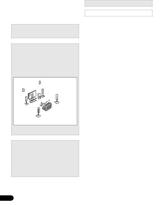
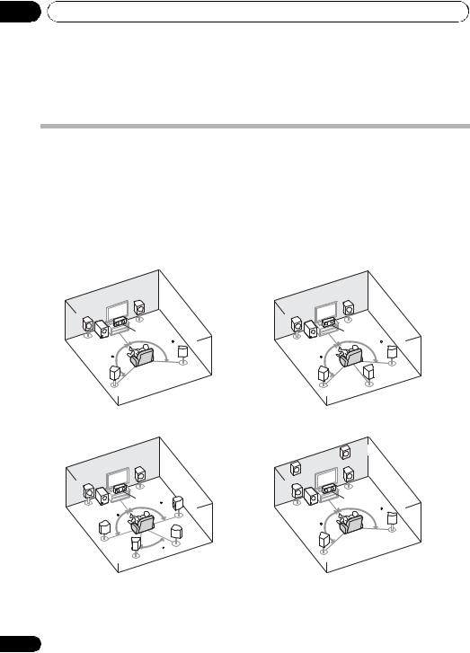
Where you place the speakers will have a big effect on the sound. Place your speakers as shown below for the best surround sound effect.
•Placing the speakers (page 16)
•Connecting the speakers (page 18)
•Connect the surround back or front height speakers (page 19)
*Front Height
Right (FHR)
*Front Height |
|
|
Left (FHL) |
Subwoofer (SW) |
Listening |
|
Front |
|
|
Right (R) |
position |
Front |
|
Surround |
|
Right (SR) |
|
Left (L) |
|
|
|
Center (C) |
|
|
|
*Surround Back |
|
Surround |
Right (SBR) |
|
|
|
|
Left (SL) |
|
*Surround Back
Left (SBL)
You can connect only one of either the surround back speaker or the front height speaker.
3 Connecting the components
For surround sound, you’ll want to hook up using a digital connection from the BD/DVD player to the receiver.
•About video outputs connection (page 22)
•Connecting a TV and playback components (page 23)
•Connecting antennas (page 27)
•Plugging in the receiver (page 28)
4 Power On
Make sure you’ve set the video input on your TV to this receiver. Check the manual that came with the TV if you don’t know how to do this.
5The Pre Out Setting (page 47)
(When connecting the front height speakers.)
The Input Assign menu (page 46)
(When using connections other than the recommended connections.)
6Use the on-screen automatic MCACC setup to set up your system
•Automatically setting up for surround sound (MCACC) (page 29)
7Basic playback (page 32)
8Adjusting the sound as desired
•Using the various listening modes
•Using the Sound Retriever (page 36)
•Better sound using Phase Control (page 36)
•Listening with Acoustic Calibration EQ (page 37)
•Using surround back channel processing (page 37)
•Setting the Up Mix function (page 38)
•Setting the Audio options (page 38)
•Choosing the input signal (page 41)
•Manual speaker setup (page 43)
9Making maximum use of the remote control
•Setting the remote to control other components (page 51)
6
En
Before you start
Chapter 1:
Before you start
Checking what’s in the box
Please check that you’ve received the following supplied accessories:
•Setup microphone
•Remote control
•Dry cell batteries (AAA size IEC R03) x2
•AM loop antenna
•FM wire antenna
•iPod cable
•These operating instructions
•Batteries with the same shape may have different voltages. Do not use different batteries together.
•When disposing of used batteries, please comply with governmental regulations or environmental public instruction’s rules that apply in your country or area.
•Do not use or store batteries in direct sunlight or other excessively hot place, such as inside a car or near a heater. This can cause batteries to leak, overheat, explode or catch fire. It can also reduce the life or performance of batteries.
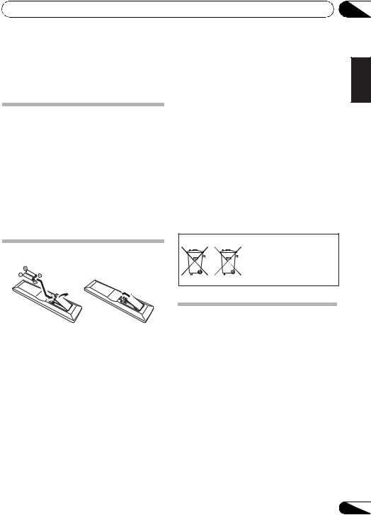
|
(Symbol examples for batteries) |
|
Loading the batteries |
|
These symbols are only valid |
|
|
in the European Union. |
|
Pb |
K058c_A1_En |
|
|
|
The batteries included with the unit are to check initial operations; they may not last over a long period. We recommend using alkaline batteries that have a longer life.
 CAUTION
Incorrect use of batteries may result in such hazards as leakage and bursting. Observe the following precautions:
•Never use new and old batteries together.
•Insert the plus and minus sides of the batteries properly according to the marks in the battery case.
Installing the receiver
•When installing this unit, make sure to put it on a level and stable surface.
Don’t install it on the following places:
–on a color TV (the screen may distort)
–near a cassette deck (or close to a device that gives off a magnetic field). This may interfere with the sound.
–in direct sunlight
–in damp or wet areas
–in extremely hot or cold areas
–in places where there is vibration or other movement
–in places that are very dusty
–in places that have hot fumes or oils (such as a kitchen)
01
Español Nederlands Italiano Français Deutsch English
Español Nederlands Italiano Français Deutsch English
7
En
01 Before you start
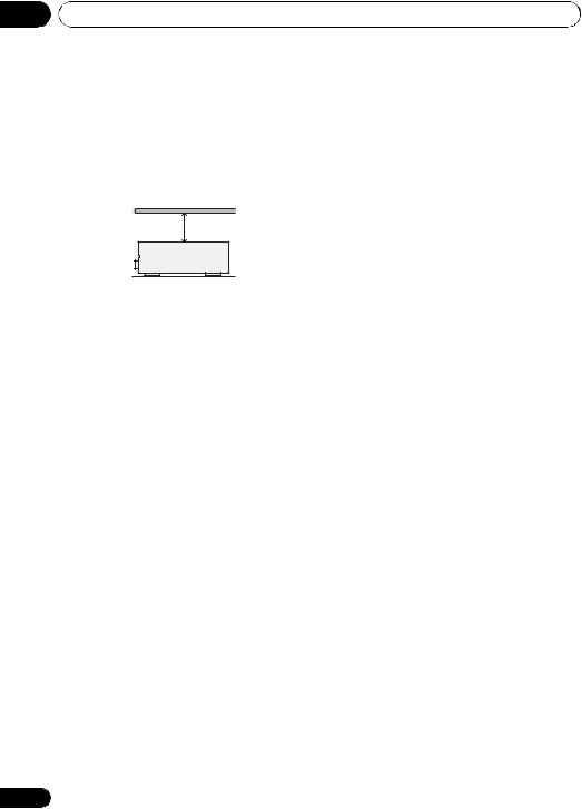
Ventilation
When installing this unit, make sure to leave space around the unit for ventilation to improve heat dispersal (at least 40 cm (16 in.) at the top). If not enough space is provided between the unit and walls or other equipment, heat will build up inside, interfering with performance and/or causing malfunctions.
40 cm (16 inches)
Receiver
Slot and openings in the cabinet are provided for ventilation and to protect the equipment from overheating. To prevent fire hazard, do not place anything directly on top of the unit, make sure the openings are never blocked or covered with items (such as newspapers, table-cloths and curtains), and do not operate the equipment on thick carpet or a bed.
8
En
Controls and displays
Chapter 2:
Controls and displays
02
English
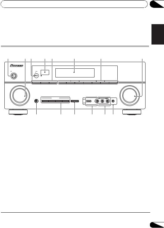
Front panel
1 |
2 |
3 |
4 |
5 |
|
6 |
|
7 |
8 |
|
|
|
|
|
|
|
|
|
AUDIO/ VIDEO MULTICHANNEL RECEIVER VSX-820 |
|
|
PHASE |
|
|
|
|
|
|
|
|
|
CONTROL |
|
|
|
|
|
|
|
STANDBY/ON |
|
|
|
|
|
|
|
|
|
|
|
SPEAKERS |
DIMMER |
DISPLAY |
BAND |
TUNE |
TUNER EDIT |
PRESET |
ENTER |
INPUT |
|
|
|
|
|
|
|
|
MASTER |
SELECTOR |
|
|
|
|
|
|
|
|
VOLUME |
|
|
PHONES |
|
LISTENING MODE |
iPod iPhone |
|
VIDEO INPUT |
|
|
|
|
|
AUTO/DIRECT |
STEREO/ALC |
STANDARD ADV SURROUND |
DIRECT CONTROL |
|
|
|
iPod |
|
|
|
|
iPhone |
|
|
|
|
USB |
|
|
|
MCACC |
VIDEO |
L |
AUDIO |
R |
SETUP MIC |
9 |
10 |
11 |
1STANDBY/ON
2INPUT SELECTOR dial
Selects an input source.
3MCACC indicator
Lights when Acoustic Calibration EQ (page 37) is on (Acoustic Calibration EQ is automatically set to on after the Auto MCACC Setup
(page 29)).
4 Remote sensor
Receives the signals from the remote control (see Operating range of remote control on page 10).
5SPEAKERS
Use to change the speaker system (page 20).
DIMMER
Dims or brightens the display. The brightness can be controlled in four steps.
12 13 14
DISPLAY
Switches the display of this unit. The listening mode, sound volume, Pre Out setting or input name can be checked by selecting an input source.1
6Character display
See Display on page 11.
7Tuner control buttons
BAND
Switches between AM, FM ST (stereo) and FM MONO radio bands (page 48).
TUNE /
Used to find radio frequencies (page 48) and SIRIUS Radio channels (page 66).
TUNER EDIT
Use with TUNE /, PRESET / and ENTER to memorize and name stations for recall (page 48, 49). Used to preset the channel in SIRIUS Radio (page 66).
 Note
Note
1 The Pre Out setting may or may not be displayed, depending on the input source you have selected.
Español Nederlands Italiano Français Deutsch
9
En
02 Controls and displays
PRESET /
Use to select preset radio stations (page 49) and to select SIRIUS Radio channels (page 66).
8MASTER VOLUME dial
9PHONES jack
Use to connect headphones. When the headphones are connected, there is no sound output from the speakers (page 41).
10Listening mode buttons
AUTO/DIRECT
Switches between Auto surround mode (Auto playback on page 33) and Stream Direct playback. Stream Direct playback bypasses the tone controls for the most accurate reproduction of a source (page 36).
STEREO/ALC
Switches between stereo playback, Auto level control stereo mode (page 35) and Front Stage Surround Advance modes (page 35).
STANDARD
Press for Standard decoding and to switch between the various 2Pro Logic II, 2Pro Logic IIx, 2Pro Logic IIz and NEO:6 options (page 32).
ADV SURROUND
Switches between the various surround modes (page 34).
11iPod iPhone DIRECT CONTROL
Change the receiver’s input to the iPod and enable iPod operations on the iPod (page 60).
12 iPod iPhone/USB terminal
Use to connect your Apple iPod or USB mass storage device as an audio source (page 58 and page 61).
13 AUDIO/VIDEO input
See Connecting to the front panel video terminal on page 28.
10
14 MCACC SETUP MIC jack
Use to connect a microphone when performing Auto MCACC setup.
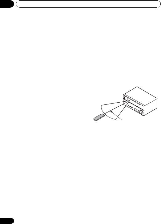
Operating range of remote control
The remote control may not work properly if:
•There are obstacles between the remote control and the receiver’s remote sensor.
•Direct sunlight or fluorescent light is shining onto the remote sensor.
•The receiver is located near a device that is emitting infrared rays.
•The receiver is operated simultaneously with another infrared remote control unit.
30° 


 30°
30° 
7 m (23 ft.)
En
Controls and displays |
02 |
Display
1 |
2 |
3 |
4 |
5 |
6 |
7 |
8 |
9 |
10 |
11 |
12 |
13 |
14 |
13 |
15 |
1 PHASE
Lights when the Phase Control is switched on (page 36).
2 AUTO
Lights when the Auto Surround feature is switched on (see Auto playback on page 33).
3 ST
Lights when a stereo FM broadcast is being received in auto stereo mode.
4 TUNE
Lights when a normal broadcast channel or SIRIUS channel is being received.
5 Speaker indicators
Lights to indicate the current speaker system, A and/or B (page 20).
6 Sleep timer indicator
Lights when the receiver is in sleep mode (page 13).
7Tuner/SIRIUS preset indicators
PRESET
Shows when a preset radio station is registered or called.
MEM
Blinks when a radio station is registered.
8PRESET information or input signal indicator
Shows the preset number of the tuner or the input signal type, etc.
9 Character display
Displays various system information.
10DTS indicators
DTS
Lights when a source with DTS encoded audio signals is detected.
HD
Lights when a source with DTS-EXPRESS or DTS-HD encoded audio signals is detected.
ES
Lights to indicate DTS-ES decoding.
96/24
Lights when a source with DTS 96/24 encoded audio signals is detected.
NEO:6
When one of the NEO:6 modes of the receiver is on, this lights to indicate NEO:6 processing (page 33).
11Dolby Digital indicators
2D
Lights when a Dolby Digital encoded signal is detected.
2D+
Lights when a source with Dolby Digital Plus encoded audio signals is detected.
Español Nederlands Italiano Français Deutsch English
11
En

02 Controls and displays
2HD
Lights when a source with Dolby TrueHD encoded audio signals is detected.
EX
Lights to indicate Dolby Digital EX decoding.
2PLll(x)
Lights to indicate 2Pro Logic II / 2Pro Logic IIx decoding. Light will go off during 2Pro Logic IIz decoding. (see Listening in surround sound on page 33 for more on this).
12 ADV.S.
Lights when one of the Advanced Surround modes has been selected (see Using the Advanced surround effects on page 34 for more on this).
13SIGNAL SELECT indicators
DIGITAL
Lights when a digital audio signal is selected.
Blinks when a digital audio signal is selected and selected audio input is not provided.
HDMI
Lights when an HDMI signal is selected. Blinks when an HDMI signal is selected and selected HDMI input is not provided.
14Up Mix/DIMMER indicator
Lights when the Up Mix function is set to ON (see page 37). Also, lights when DIMMER is set to off.
15 DIR.
Lights when the DIRECT or PURE DIRECT mode is switched on (page 36).
12
En
Controls and displays
Remote control
1 |
|
|
|
12 |
|
RECEIVER |
SLEEP |
SOURCE |
TV |
2 |
CONTROL |
|||
|
|
|
|
|
3 |
RECEIVER |
INPUT SELECT |
|
|
|
|
|
INPUT |
|
4 |
BD |
DVD |
TV |
13 |
|
DVR |
CD |
CD-R |
CH |
5 |
|
|||
|
|
|
|
|
|
ADAPTER |
iPod USB |
VIDEO |
|
|
TUNER |
SIRIUS |
SIGNAL SEL |
VOL |
6 |
AUTO/ |
STEREO/ |
|
BD MENU |
|
|
|||
7 |
DIRECT |
A.L.C. |
STANDARD |
ADV SURR |
|
|
|
|
|
|
AUDIO |
|
TUNER EDIT |
MASTER |
|
PARAMETER |
|
TOOLS |
VOLUME |
|
TOP |
TUNE |
MENU |
|
|
|
|
||
8 |
MENU |
|
|
|
|
T |
|
P |
|
|
E |
|
R |
14 |
|
P |
|
E |
|
|
S |
ENTER |
E |
|
|
E |
S |
|
|
9 |
R |
|
T |
|
|
|
|
||
|
HOME |
|
|
|
|
MENU |
TUNE |
|
|
|
SETUP |
BAND |
||
|
iPod CTRL |
|
RETURN |
|
CATEGORY
DTV/ TV MUTE
10 |
|
|
|
|
15 |
BASS |
TRE |
|
|||
|
|
|
|
MEMORY |
|
|
HDD |
DVD |
VCR |
|
16 |
|
1 |
2 |
3 |
DISP |
|
|
S.RETRIEVER |
SB CH |
CH SELECT |
EQ |
|
11 |
4 |
5 |
6 |
CH |
|
MIDNIGHT SPEAKERS |
LEV |
PHASE |
|
||
|
7 |
8 |
9 |
CH |
|
|
DIMMER |
|
LEV |
SHIFT |
17 |
|
0 |
|
|||
|
CLR |
ENTER |
|
||
|
/ +10 |
|
|
|
|
|
D.ACCESS |
|
|
|
|
|
|
RECEIVER |
|
|
|
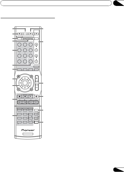
1 SLEEP
Press to change the amount of time before the receiver switches into standby (30 min – 60 min – 90 min – Off). You can check the remaining sleep time at any time by pressing
SLEEP once.
02
2 |
RECEIVER |
|
|||
Switches the receiver between standby and on. |
English |
||||
|
|
|
|
||
3 |
|
RECEIVER |
|
||
Switches the remote to control the receiver |
|
||||
(used to select the white commands above the |
|
||||
number buttons (S.RETRIEVER, etc)). Also use |
|
||||
this button to set up surround sound (page 42) |
Deutsch |
||||
Use to select the input source. |
|||||
or Audio parameters (page 38). |
|
||||
4 |
INPUT SELECT |
|
|||
|
|
|
|
|
|
5 |
MULTI CONTROL buttons |
|
|||
Press to select control of other components |
Français |
||||
(see Controlling the rest of your system on |
|||||
|
|||||
page 51). |
|
||||
6 |
SIGNAL SEL |
|
|||
Use to select an input signal (page 41).
7 Listening mode buttons |
Italiano |
|
Switches between Auto surround mode |
||
AUTO/DIRECT |
|
|
(Auto playback on page 33) and Stream |
|
|
Direct playback. Stream Direct playback |
|
|
Nederlands |
||
bypasses the tone controls for the most |
||
|
||
accurate reproduction of a source |
|
|
(page 36). |
|
|
STEREO/A.L.C. |
|
|
Switches between stereo playback, Auto |
|
|
level control stereo mode (page 35) and |
Español |
|
Front Stage Surround Advance modes |
||
|
||
(page 35). |
|
|
STANDARD |
|
|
Press for Standard decoding and to switch |
|
|
between 2Pro Logic II options (page 33). |
|
|
ADV SURR |
|
|
Switches between the various surround |
|
|
modes (page 34). |
|
|
Press BD first to access: |
|
|
BD MENU* |
|
|
Displays the disc menu of Blu-ray Discs. |
|
13
En

02 Controls and displays
8 System Setup and component control buttons
The following button controls can be accessed after you have selected the corresponding
MULTI CONTROL button (BD, DVD, etc.).
Press RECEIVER first to access:
AUDIO PARAMETER
Use to access the Audio options (page 38).
SETUP
Press to access the System Setup menu (page 42).
RETURN
Confirm and exit the current menu screen.
Press BD, DVD or DVR first to access:
TOP MENU
Displays the disc ‘top’ menu of a BD/DVD.
HOME MENU
Displays the HOME MENU screen.
RETURN
Confirm and exit the current menu screen.
MENU
Displays the TOOLS menu of Blu-ray Disc player.
Press TUNER or SIRIUS first to access:
TUNER EDIT
Memorizes stations for recall (page 48 and 67). When TUNER is pressed, also used to change the name (page 49).
BAND
Switches between AM, FM ST (stereo) and FM MONO radio bands (page 48).
CATEGORY
Press to browse SIRIUS radio broadcasts.
Press iPod USB first to access:
iPod CTRL
Switches between the iPod controls and the receiver controls (page 60).
9 (TUNE /, PRESET /),
ENTER
Use the arrow buttons when setting up your surround sound system (page 42). Also used to control BD/DVD menus/options.
Use the TUNE / buttons can be used to find radio frequencies (page 48) and the PRESET / buttons can be used to select preset radio stations (page 49).
10 Component control buttons
The main buttons ( , , etc.) are used to control a component after you have selected it using the input source buttons.
The controls above these buttons can be accessed after you have selected the corresponding input source button (BD, DVD, DVR and CD). These buttons also function as described below.
Press RECEIVER first to access:
BASS –/+
Use to adjust Bass1
TRE –/+
Use to adjust Treble1
Press TV first to access:
DTV/TV
Switches between the DTV and analog TV input modes for Pioneer flat panel TVs.
11 Number buttons and other component controls
Use the number buttons to directly select a radio frequency (page 48) or the tracks on a CD, etc. There are other buttons that can be
accessed after the RECEIVER button is pressed. (For example MIDNIGHT, etc.)
HDD*, DVD*, VCR*
These buttons switch between the hard disk, DVD and VCR controls for HDD/DVD/ VCR recorders.
 Note
Note
1 The tone controls are disabled when the listening mode is set to DIRECT or PURE DIRECT.
14
En

Controls and displays |
02 |
S.RETRIEVER
Press to restore CD quality sound to compressed audio sources (page 36).
SB CH
Press to select ON, AUTO, OFF the surround back channel.
CH SELECT
Press repeatedly to select a channel, then use LEV +/– to adjust the level (page 45).
LEV +/–
Use to adjust the channel level.
EQ
Press to switch on/off Acoustic Calibration EQ setting (page 37).
MIDNIGHT
Switches to Midnight or Loudness listening (page 39).
SPEAKERS
Use to change the speaker system (page 20).
PHASE
Press to switch on/off Phase Control (page 36).
DIMMER
Dims or brightens the display. The brightness can be controlled in four steps.
Press SIRIUS first to access:
D.ACCESS
After pressing, you can access a radio station directly using the number buttons (page 66).
12 SOURCE
Press to turn on/off other components connected to the receiver (see page 54 for more on this).
13 TV CONTROL buttons
These buttons are dedicated to control the TV assigned to the TV button. Thus if you only have one TV to hook up to this system assign it to the TV button (see page 53 for more on this).
Use to turn on/off the power of the TV.
INPUT
Use to select the TV input signal.
CH +/–
Use to select channels.
VOL +/–
Use to adjust the volume on your TV.
14MASTER VOLUME +/–
Use to set the listening volume.
15MUTE
Mutes/unmutes the sound.
16 DISP
Switches the display of this unit. The listening mode, sound volume, Pre Out setting or input name can be checked by selecting an input source.1
17 SHIFT
Press to access the ‘boxed’ commands (above the buttons) on the remote. These buttons are marked with an asterisk (* ) in this section.
Español Nederlands Italiano Français Deutsch English
 Note
Note
1 The Pre Out setting may or may not be displayed, depending on the input source you have selected.
15
En
03 Connecting your equipment
Chapter 3:
Connecting your equipment
Placing the speakers
By connecting the left and right front speakers (L/R), the center speaker (C), the left and right surround speakers (SL/SR), and the subwoofer (SW), a 5.1 ch surround system can be enjoyed.
Further, by using an external amplifier, you can connect the left and right surround back speakers (SBL/SBR) and the left and right front height speaker (FHL/FHR) to boost your system up to a 7.1 ch surround system.
• You can also connect one surround back speaker (SB) and enjoy a 6.1 ch surround system. To achieve the best possible surround sound, install your speakers as shown below.
5.1 channel surround system: |
6.1 channel surround |
|
|||
|
|
|
(Surround back) system: a |
||
|
R |
|
|
R |
|
L |
|
|
L |
|
|
|
C |
|
|
C |
|
SW |
120 |
|
SW |
|
120 |
120 |
|
|
120 |
|
|
|
|
SR |
|
|
SR |
SL |
|
|
SL |
SB |
|
|
|
|
|
||
7.1 channel surround |
|
7.1 channel surround |
|
||
(Surround back) system: a |
|
(Front height) system: a |
|||
|
|
|
|
FHR |
|
|
R |
|
FHL |
|
|
|
|
|
R |
|
|
L |
|
|
|
|
|
|
|
|
|
|
|
|
C |
|
L |
C |
|
|
SR |
|
|
||
|
90 |
|
|
|
|
SW |
|
SW |
|
120 |
|
|
|
|
|||
90 |
|
|
|
|
|
|
|
|
120 |
|
|
SL |
|
SBR |
|
|
SR |
60 |
|
|
|
|
|
SBL |
|
SL |
|
|
|
|
|
|
|
||
a. This layout is available only when the additional amplifier is connected to the unit and the surround back or front height speakers are connected to the amplifier. For details, see Connect the surround back or front height speakers on page 19.
16
En

Connecting your equipment |
03 |
Hints on the speaker placement
Where you put your speakers in the room has a big effect on the quality of the sound. The following guidelines should help you to get the best sound from your system.
•The subwoofer can be placed on the floor. Ideally, the other speakers should be at about ear-level when you’re listening to them. Putting the speakers on the floor (except the subwoofer), or mounting them very high on a wall is not recommended.
•For the best stereo effect, place the front speakers 2 m to 3 m (6 ft. to 9 ft.) apart, at equal distance from the TV.
•If you’re going to place speakers around your CRT TV, use shielded speakers or place the speakers at a sufficient distance from your CRT TV.
•If you’re using a center speaker, place the front speakers at a wider angle. If not, place them at a narrower angle.
•Place the center speaker above or below the TV so that the sound of the center channel is localized at the TV screen. Also, make sure the center speaker does not cross the line formed by the leading edge of the front left and right speakers.
•It is best to angle the speakers towards the listening position. The angle depends on the size of the room. Use less of an angle for bigger rooms.
•Surround and surround back speakers should be positioned 60 cm to 90 cm (2 ft. to 3 ft.) higher than your ears and titled slight downward. Make sure the speakers don’t face each other. For DVD-Audio, the speakers should be more directly behind the listener than for home theater playback.
•If the surround speakers cannot be set directly to the side of the listening position with a 7.1-channel system, the surround effect can be enhanced by turning off the Up Mix function (see Setting the Up Mix function on page 38).
•Try not to place the surround speakers farther away from the listening position than the front and center speakers. Doing so can weaken the surround sound effect.
•Place the left and right front height speakers at least one meter directly above the left and right front speakers.
 CAUTION
•Make sure that all speakers are securely installed. This not only improves sound quality, but also reduces the risk of damage or injury resulting from speakers being knocked over or falling in the event of external shocks such as earthquakes.
 Important
•To connect the surround back or front height speakers, an additional amplifier is required. Connect the additional amplifier to the PRE OUT SURR BACK/FRONT HEIGHT outputs of this unit and connect the surround back or front height speakers to the additional amplifier (see
Connect the surround back or front height speakers on page 19).
The Pre Out setting must be set if the above connections are performed. Select SURR.BACK if the surround back speaker is connected and HEIGHT if the front height speaker is connected (If neither the surround back speaker nor the front height speaker is connected, either setting will suffice) (see The Pre Out Setting on
page 47).
Español Nederlands Italiano Français Deutsch English
17
En
03 Connecting your equipment
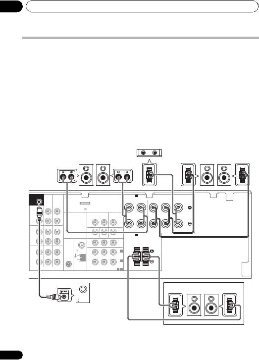
Connecting the speakers
The receiver will work with just two stereo speakers (the front speakers in the diagram) but using at least three speakers is recommended, and a complete setup is best for surround sound.
Make sure you connect the speaker on the right to the right (R) terminal and the speaker on the left to the left (L) terminal. Also make sure the positive and negative (+/–) terminals on the receiver match those on the speakers.
You can use the speakers connected to the B speaker terminals to listen to stereo playback in another room. See Switching the speaker system on page 20 for the listening options with this setup.
You can use speakers with a normal impedance between 6 Ω and 16 Ω.
However, note that only the front speakers are set to a value between 12 Ω and 16 Ω if you select SP AB in Switching the speaker system on page 20.
Be sure to complete all connections before connecting this unit to the AC power source.
|
|
Center speaker |
|
|
Front speakers |
C |
Surround speakers |
||
L |
R |
|
SL |
SR |
SUBWOOFER |
|
|
|
|
|
|
|
|
SPEAKERS A |
|
|
|
|
PRE OUT |
|
|
|
|
|
|
|
|
|
FRONT |
|
R SURROUND L |
CENTER |
|
CD-R/TAPE DVR/VCR |
|
|
|
|
|
|
R |
L |
||||
|
|
|
|
|
|
|
|
|
|
|
|
||
SURR |
|
|
ADAPTER PORT |
|
|
|
|
|
|
|
|
|
|
FRONT |
|
|
(OUTPUT 5 V |
100 mA MAX) |
|
|
|
|
|
|
|
|
|
HEIGHT |
|
|
|
|
|
|
|
|
|
|
|
|
|
L |
|
|
|
VIDEO |
DVR/VCR |
TV/SAT |
|
|
|
|
|
||
(Single |
|
OUT |
|
|
|
|
|
|
|
||||
|
|
|
OUT |
IN |
|
IN |
|
|
|
|
|
||
|
|
|
|
|
|
|
|
|
|
||||
R |
|
|
|
|
|
|
|
|
|
|
|
|
|
PRE OUT |
|
|
|
|
|
|
|
|
|
|
|
|
|
CD |
CD-R/TAPE DVR/VCR |
|
|
|
|
|
|
|
|
|
|
|
|
L |
|
|
|
|
|
|
|
|
|
|
|
|
|
IN |
|
IN |
|
MONITOR OUT |
DVD IN |
|
BD IN |
SPEAKERS B |
|
Class 2 Wiring |
|
||
|
|
|
|
|
|
|
|
||||||
R |
|
|
ANTENNA |
PR |
|
PB |
Y |
MONITOR |
|
|
|
|
|
|
|
|
|
|
|
|
OUT |
|
|
|
|
||
|
|
|
|
|
|
|
|
R |
|
L |
|
||
TV/SAT |
DVD |
BD |
FM |
|
|
|
|
|
|
|
|
||
|
|
|
|
|
|
|
|
|
|
||||
UNBAL |
|
|
|
|
|
|
|
|
|
|
|||
L |
|
|
75 |
|
|
|
|
IN 2 |
|
|
|
|
|
|
|
SIRIUS |
|
|
|
|
(DVD) |
|
|
|
|
||
|
|
|
IN |
|
|
|
|
|
|
|
|
||
IN |
|
IN |
|
|
|
|
|
|
|
|
|
|
|
|
|
|
|
|
|
|
|
|
|
|
|
||
R |
|
|
AM |
|
|
|
|
IN 1 |
|
|
|
|
|
|
|
|
|
|
|
(BD) |
|
|
|
|
|||
|
|
|
LOOP |
|
|
|
|
|
|
|
|
||
|
|
|
|
|
|
ASSIGNABLE |
|
|
|
|
|||
|
|
|
|
|
|
|
|
|
|
|
|||
|
AUDIO |
|
|
COMPONENT VIDEO |
|
1 |
2 |
|
|
|
|
||
Speaker system B
L R
SW
Powered subwoofer
18
En
Connecting your equipment |
03 |
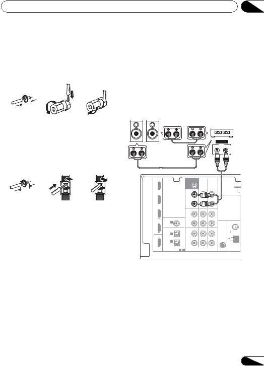
Bare wire connections
A-Speaker terminals:
1Twist exposed wire strands together.
2Loosen terminal and insert exposed wire.
3Tighten terminal.
1 |
2 |
3 |
10 mm (3/8 in.)
B-Speaker terminals:
1Twist exposed wire strands together.
2Push open the tabs and insert exposed wire.
3Release the tabs.
1 |
2 |
3 |
10 mm (3/8 in.)
 CAUTION
•These speaker terminals carry
HAZARDOUS LIVE voltage. To prevent the risk of electric shock when connecting or disconnecting the speaker cables, disconnect the power cord before touching any uninsulated parts.
•Make sure that all the bare speaker wire is twisted together and inserted fully into the speaker terminal. If any of the bare speaker wire touches the back panel it may cause the power to cut off as a safety measure.
Connect the surround back or front |
|
|
|
||
height speakers |
English |
|
Connect the PRE OUT outputs of the unit and |
||
|
||
additional amplifier to add a surround back or |
|
|
front height speaker. |
|
|
|
|
• If the surround back speaker or the front |
|
||||||
height speaker is connected, set the Pre |
Deutsch |
||||||
Out setting (see The Pre Out Setting on |
|||||||
page 47). |
|
|
|
|
|
|
|
Surround back or |
|
|
|
|
|
||
|
|
|
|
|
|
||
front height speakers |
|
|
Surround back or |
|
|||
SBL/FHL SBR/FHR |
|
|
|
||||
|
|
|
front height |
Français |
|||
|
|
|
|
channel amplifier |
|||
|
|
|
|
|
|
ANALOG |
|
|
|
|
|
|
|
INPUT |
|
|
|
|
|
|
L |
R |
|
IN BD |
|
|
SUBWOOFER |
|
|
|
Italiano |
|
|
|
PRE OUT |
|
|
|
|
|
|
|
|
CD-R/TAPE DVR/VCR |
|
|
|
|
|
|
SURR BACK / |
|
|
ADAPTER |
Nederlands |
DVD |
|
|
FRONT |
|
|
(OUTPUT 5 V |
|
|
|
HEIGHT |
|
|
|
||
|
|
|
L |
|
|
|
|
|
|
|
(Single) |
|
OUT |
|
|
|
|
|
R |
|
|
|
|
TV/SAT |
|
|
PRE OUT |
|
|
|
|
|
|
CD |
CD-R/TAPE DVR/VCR |
|
|||
|
|
|
|
||||
|
|
|
L |
|
|
|
|
|
COAXIAL |
ASSIGNABLE |
IN |
|
IN |
ANTENNA |
|
DVR/VCR |
IN 1 |
|
R |
|
|
||
|
|
|
|
||||
|
(CD) |
|
|
|
|
||
|
|
|
|
|
|
||
|
OPTICAL |
|
TV/SAT |
DVD |
BD |
FM |
|
|
|
UNBAL |
|
||||
|
IN 2 |
|
L |
|
|
75 |
Español |
OUT |
|
|
|
SIRIUS |
|||
|
|
IN |
|
IN |
IN |
||
|
|
|
|
|
|||
|
IN 1 |
|
R |
|
|
AM |
|
|
(CD-R/TAPE) |
|
|
||||
|
|
ASSIGNABLE |
|
|
|
LOOP |
|
HDMI |
|
1 2 |
|
AUDIO |
|
|
|
|
|
|
|
|
|
|
|
•You can use the additional amplifier on the surround back channel pre-outs for a single speaker as well. In this case plug the amplifier into the left (L (Single)) terminal only.
19
En
03 Connecting your equipment
Switching the speaker system
Three speaker system settings are possible using the SPEAKERS button.
• Use the SPEAKERS button on the front panel to select a speaker system setting.1
|
SPEAKERS |
DIMMER |
DISPLAY |
|
|
|
|
|
|
|
|
|
|
|
Press repeatedly to choose a speaker system option:
•SP A – Sound is output from the speakers connected to the A speaker terminals and
PRE OUT SURR BACK/FRONT HEIGHT
(multichannel playback is possible).
•SP B – Sound is output from the two speakers connected to speaker system B (only stereo playback is possible).
•SP AB – Sound is output from speaker system A, the two speakers in speaker system B, and the subwoofer. Multichannel sources are downmixed only when the STEREO or ALC mode is selected
for stereo output from speaker systems A and B.2
•SP – No sound is output from the speakers.
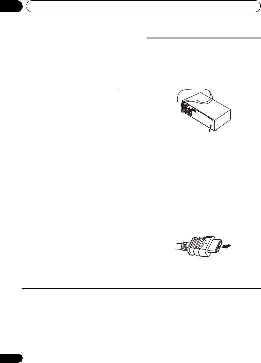
Making cable connections
Make sure not to bend the cables over the top of this unit (as shown in the illustration). If this happens, the magnetic field produced by the transformers in this unit may cause a humming noise from the speakers.
 Important
•Before making or changing connections, switch off the power and disconnect the power cord from the AC outlet.
•Before unplugging the power cord, switch the power into standby.
HDMI cables
Both video and sound signals can be transmitted simultaneously with one cable. If connecting the player and the TV via this receiver, for both connections, use HDMI cables.3
HDMI cable
Be careful to connect the terminal in the proper direction.
 Note
Note
1The subwoofer output depends on the settings you made in Speaker Setting on page 43. However, if SP B is selected above, no sound is heard from the subwoofer (the LFE channel is not downmixed).
2You can use speakers with a normal impedance between 6 Ω and 16 Ω. However, be aware that only the front speakers are set to a value between 12 Ω and 16 Ω when you select SP AB.
3• Set the HDMI parameter in Setting the Audio options on page 38 to THRU (THROUGH) and set the input signal in Choosing the input signal on page 41 to HDMI, if you want to hear HDMI audio output from your TV or flat panel TV (no sound will be heard from this receiver).
•If the video signal does not appear on your TV or flat panel TV, try adjusting the resolution settings on your component or display. Note that some components (such as video game units) have resolutions that may not be displayed. In this case, use a (analog) composite connection.
•When the video signal from the HDMI is 480i, 480p, 576i or 576p, Multi Ch PCM sound and HD sound cannot be received.
20
En
Connecting your equipment |
03 |
About HDMI
The HDMI connection transfers uncompressed digital video, as well as almost every kind of digital audio that the connected component is compatible with, including DVDVideo, DVD-Audio, SACD, Dolby Digital Plus, Dolby TrueHD, DTS-HD Master Audio (see below for limitations), Video CD/Super VCD and CD.
This receiver incorporates High-Definition Multimedia Interface (HDMI®) technology.
This receiver supports the functions described below through HDMI connections.1
•Digital transfer of uncompressed video (contents protected by HDCP (1080p/24, 1080p/60, etc.))
•3D signal transfer2
•Deep Color signal transfer2
•x.v.Color signal transfer2
•Input of multi-channel linear PCM digital audio signals (192 kHz or less) for up to 8 channels
•Input of the following digital audio formats:3
– Dolby Digital, Dolby Digital Plus, DTS, High bitrate audio (Dolby TrueHD, DTS-HD Master Audio), DVD-Audio, CD, SACD (DSD signal), Video CD, Super VCD
HDMI, the HDMI logo and High-Definition Multimedia Interface are trademarks or registered trademarks of HDMI Licensing, LLC.
“x.v.Color” and x.v.Color logo are trademarks of Sony Corporation.
Analog audio cables
Use stereo RCA phono cables to connect analog audio components. These cables are typically red and white, and you should connect the red plugs to R (right) terminals and white plugs to L (left) terminals.
Analog audio cables
Right (red) 
Left (white)
Digital audio cables
Commercially available coaxial digital audio cables or optical cables should be used to connect digital components to this receiver.4
Coaxial digital audio cable |
Optical cable |
Video cables
Standard RCA video cables
These cables are the most common type of video connection and are used to connect to the composite video terminals. The yellow plugs distinguish them from cables for audio.
Standard RCA video cable
Note
1• Use a High Speed HDMI® cable. If HDMI cable other than a High Speed HDMI® cable is used, it may not work properly.
•When an HDMI cable with a built-in equalizer is connected, it may not operate properly.
2Signal transfer is only possible when connected to a compatible component.
3• HDMI format digital audio transmissions require a longer time to be recognized. Due to this, interruption in the audio may occur when switching between audio formats or beginning playback.
•Turning on/off the device connected to this unit's HDMI OUT terminal during playback, or disconnecting/connecting the HDMI cable during playback, may cause noise or interrupted audio.
4• When connecting optical cables, be careful when inserting the plug not to damage the shutter protecting the optical socket.
•When storing optical cable, coil loosely. The cable may be damaged if bent around sharp corners.
•You can also use a standard RCA video cable for coaxial digital connections.
Español Nederlands Italiano Français Deutsch English
21
En
03 Connecting your equipment
Component video cables
Use component video cables to get the best possible color reproduction of your video source. The color signal of the TV is divided into the luminance (Y) signal and the color (PB and PR) signals and then output. In this way, interference between the signals is avoided.
Component video cables
Green (Y)
Blue (PB)
Red (PR)
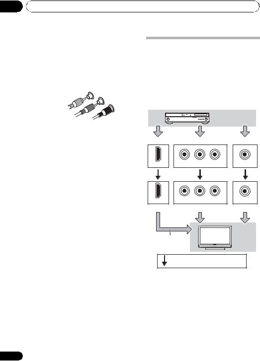
About video outputs connection
This receiver is not loaded with a video converter. When you use component video cables or HDMI cables for connecting to the input device, the same cables should be used for connecting to the TV.
The signals input from the analog (composite and component) video inputs of this unit will not be output from the HDMI OUT.
Playback component
Terminal for connection with source device
PR PB Y
HDMI IN |
|
COMPONENT VIDEO IN |
VIDEO IN |
|
|
PR |
PB |
Y |
|
HDMI OUT |
COMPONENT VIDEO OUT |
MONITOR OUT |
||
Terminal for connection with TV monitor
The OSD will not appear.
TV
Video signals can be output.
22
En
Connecting your equipment
Connecting a TV and playback components
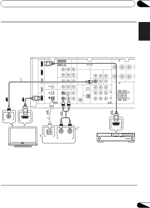
Connecting using HDMI
If you have an HDMI or DVI (with HDCP) equipped component (Blu-ray disc player, etc.), you can connect it to this receiver using a commercially available HDMI cable.
•If the receiver is connected to a TV using an HDMI cable, the OSD will not be displayed. Be sure to use a standard RCA analog video cable to connect.1
This connection is necessary in order to see the OSD of the unit on the TV.
IN BD |
|
|
SUBWOOFER |
|
|
|
|
|
|
|
SPEAKERS A |
|
|
|
|
PRE OUT |
|
|
|
|
|
|
|
R FRONT L |
R SURROUN |
|
|
|
|
CD-R/TAPE DVR/VCR |
|
|
|
|
|
|||
|
|
|
|
|
|
|
|
|
|
|
||
|
|
|
SURR BACK / |
|
|
ADAPTER PORT |
|
|
|
|
|
|
DVD |
|
|
FRONT |
|
|
(OUTPUT 5 V |
100 mA MAX) |
|
|
|
|
|
|
|
HEIGHT |
|
|
|
|
|
|
|
|
|
|
|
|
|
L |
|
|
|
VIDEO |
DVR/VCR |
TV/SAT |
|
||
|
|
|
(Single) |
|
OUT |
|
|
|
||||
|
|
|
|
|
|
OUT |
IN |
|
IN |
|
||
|
|
|
|
|
|
|
|
|
||||
|
|
|
R |
|
|
|
|
|
|
|
|
|
TV/SAT |
|
|
PRE OUT |
|
|
|
|
|
|
|
|
|
|
|
CD |
CD-R/TAPE DVR/VCR |
|
|
|
|
|
|
|
||
|
|
|
|
|
|
|
|
|
|
|||
|
|
|
L |
|
|
|
|
|
|
|
|
|
|
COAXIAL |
ASSIGNABLE IN |
|
IN |
|
MONITOR OUT |
DVD IN |
|
SPEAKERS B |
Class 2 Wiring |
||
|
|
|
|
BD IN |
|
|||||||
DVR/VCR |
IN 1 |
|
R |
|
|
ANTENNA |
PR |
|
PB |
Y |
MONITOR |
|
|
(CD) |
|
|
|
|
|
|
|
OUT |
|
||
|
|
|
|
|
|
|
|
|
L |
|||
|
OPTICAL |
|
TV/SAT |
DVD |
BD |
FM |
|
|
|
|
R |
|
|
|
UNBAL |
|
|
|
|
|
|
||||
|
IN 2 |
|
L |
|
|
75 |
|
|
|
|
IN 2 |
|
OUT |
|
|
|
SIRIUS |
|
|
|
|
(DVD) |
|
||
|
|
IN |
|
IN |
IN |
|
|
|
|
|
||
|
|
|
|
|
|
|
|
|
|
|
||
|
IN 1 |
|
R |
|
|
AM |
|
|
|
|
IN 1 |
|
|
(CD-R/TAPE) |
|
|
|
|
|
|
(BD) |
|
|||
|
|
|
|
|
|
|
|
|
||||
|
|
ASSIGNABLE |
|
|
|
LOOP |
|
|
|
ASSIGNABLE |
|
|
HDMI |
|
|
|
|
|
|
|
|
|
|||
|
1 2 |
|
AUDIO |
|
|
COMPONENT VIDEO |
|
1 2 |
|
|||
VIDEO IN |
HDMI IN |
 2
2
OPTICAL |
R |
L |
|
|
|
DIGITAL AUDIO OUT |
ANALOG AUDIO OUT |
|
Select one
HDMI/DVI-compatible TV
This connection is required in order to listen to the sound of the TV over the receiver.
HDMI OUT
HDMI/DVI-compatible
Blu-ray disc player
 Note
Note
1If you wish to see the OSD screen (for setup, etc.), switch the TV input to analog. (With HDMI input, the OSD will not be displayed.)
2If the connection was made using an optical cable, you’ll need to tell the receiver which digital input you connected the TV to (see Choosing the input signal on page 41).
03
Español Nederlands Italiano Français Deutsch English
23
En
03 Connecting your equipment
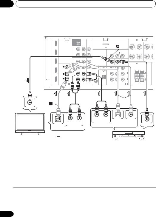
Connecting your component with no HDMI terminal
This diagram shows connections of a TV and DVD player (or other playback component) with no HDMI terminal to the receiver.
IN BD |
|
SUBWOOFER |
|
|
|
|
|
|
|
|
SPEAKERS A |
|
|
|
|
|
PRE OUT |
|
|
|
|
|
|
|
|
|
FRONT |
|
R SURROUN |
|
|
|
CD-R/TAPE DVR/VCR |
|
|
|
|
|
|
R |
L |
|||
|
|
|
|
|
|
|
|
|
|
|
|
|
||
|
|
SURR BACK / |
|
|
ADAPTER PORT |
|
|
3 |
|
|
|
|
|
|
DVD |
|
FRONT |
|
|
(OUTPUT 5 V |
100 mA MAX) |
|
|
|
|
|
|
||
|
HEIGHT |
|
|
|
|
|
|
|
|
|
|
|
|
|
|
|
L |
|
|
|
VIDEO |
DVR/VCR |
TV/SAT |
|
|
|
|
||
|
|
(Single) |
|
OUT |
|
|
|
|
|
|
||||
|
|
|
|
|
OUT |
IN |
|
IN |
|
|
|
|
||
|
|
|
|
|
|
|
|
|
|
|
||||
|
|
R |
|
|
|
|
|
|
|
|
|
|
|
|
TV/SAT |
|
PRE OUT |
|
|
|
|
|
|
|
|
|
|
|
|
|
CD |
CD-R/TAPE DVR/VCR |
|
|
|
|
|
|
|
|
|
|
||
|
|
|
|
|
|
|
|
|
|
|
|
|||
|
|
L |
|
|
|
|
|
|
|
|
|
|
|
|
|
COAXIAL |
|
|
IN |
|
MONITOR OUT |
DVD IN |
|
BD IN |
SPEAKERS B |
|
Class 2 Wiring |
||
|
|
|
|
|
|
|
|
|
||||||
DVR/VCR |
IN 1 |
|
|
|
ANTENNA |
PR |
|
PB |
Y |
MONITOR |
|
|
|
|
|
(CD) |
|
|
|
|
|
|
|
|
OUT |
R |
|
L |
|
|
OPTICAL |
TV/SAT |
DVD |
BD |
FM |
|
|
|
|
|
|
|
||
|
UNBAL |
|
|
|
|
|
|
|
|
|
||||
|
IN 2 |
L |
|
|
75 |
|
|
|
|
IN 2 |
|
|
|
|
OUT |
|
|
SIRIUS |
|
|
|
|
(DVD) |
|
|
|
|||
|
IN |
|
IN |
IN |
|
|
|
|
|
|
|
|||
|
|
|
|
|
|
|
|
|
|
|
|
|
||
|
IN 1 |
R |
|
|
AM |
|
|
|
|
IN 1 |
|
|
|
|
|
(CD-R/TAPE) |
|
|
|
|
|
|
(BD) |
|
|
|
|||
|
|
|
|
|
|
|
|
|
|
|
||||
|
ASSIGNABLE |
|
|
LOOP |
|
|
|
ASSIGNABLE |
|
|
|
|||
HDMI |
|
|
|
|
|
|
|
|
|
|||||
|
1 |
AUDIO |
|
|
COMPONENT VIDEO |
|
1 |
2 |
|
|
|
|||
 1
1
|
VIDEO IN |
|
|
|
OPTICAL |
R |
L |
|
|
|
|
|
DIGITAL AUDIO OUT ANALOG AUDIO OUT |
||
|
Select one |
|
|
|
This connection is |
||
TV |
required in order to |
||
|
listen to the sound of |
||
the TV over the receiver.
 2
2
R |
L |
OPTICAL |
COAXIAL |
ANALOG AUDIO OUT |
DIGITAL AUDIO OUT |
||
|
VIDEO OUT |
||
Select one
DVD player
 Note
Note
1If the connection was made using an optical cable, you’ll need to tell the receiver which digital input you connected the TV to (see Choosing the input signal on page 41).
2If the connection was made using an optical or a coaxial cable, you’ll need to tell the receiver which digital input you connected the DVD player to (see Choosing the input signal on page 41).
3If both TV and player has a component video jacks, you can connect these too. See Using the component video jacks on page 26 for more on this.
24
En

Connecting your equipment
Connecting a satellite receiver or other digital set-top box
Satellite and cable receivers, and terrestrial digital TV tuners are all examples of so-called ‘set-top boxes’.
SUBWOOFER |
|
PRE OUT |
|
|
CD-R/TAPE DVR/VCR |
SURR BACK / |
ADAPTER PORT |
FRONT |
(OUTPUT 5 V 100 mA MAX) |
HEIGHT |
|
|
|
|
L |
|
|
|
VIDEO |
DVR/VCR |
TV/SAT |
||
|
|
|
(Single) |
|
OUT |
|
|
||||
|
|
|
|
|
|
OUT |
IN |
|
IN |
||
|
|
|
|
|
|
|
|
||||
|
|
|
R |
|
|
|
|
|
|
|
|
|
|
|
PRE OUT |
CD-R/TAPE DVR/VCR |
|
|
|
|
|
|
|
|
|
|
CD |
|
|
|
|
|
|
||
|
|
|
L |
|
|
|
|
|
|
|
|
COAXIAL |
ASSIGNABLE |
IN |
|
IN |
|
MONITOR OUT |
DVD IN |
|
BD IN |
||
IN 1 |
|
|
R |
|
|
ANTENNA |
PR |
|
PB |
Y |
MO |
(CD) |
|
|
|
|
|
|
|
|
O |
||
|
|
|
|
|
|
|
|
|
|||
OPTICAL |
|
|
TV/SAT |
DVD |
BD |
FM |
|
|
|
|
|
|
|
UNBAL |
|
|
|
|
|
||||
IN 2 |
|
|
L |
|
|
75 |
|
|
|
|
I |
|
|
|
|
SIRIUS |
|
|
|
|
( |
||
|
|
|
|
|
|
IN |
|
|
|
|
|
|
|
|
IN |
|
IN |
|
|
|
|
|
|
|
|
|
|
|
|
|
|
|
|
||
IN 1 |
|
|
R |
|
|
AM |
|
|
|
|
I |
(CD-R/TAPE |
|
|
|
|
|
|
|
( |
|||
|
|
|
|
LOOP |
|
|
|
|
|||
|
|
|
|
|
|
|
|
|
ASSIGNA |
||
|
1 |
2 |
|
|
|
|
|
|
|
||
|
|
|
|
|
COMPONENT VIDEO |
|
1 |
||||

 2
2
1 
OPTICAL |
R |
L |
DIGITAL AUDIO OUT |
ANALOG AUDIO OUT |
|
Select one |
VIDEO OUT |
|
STB
03
|
|
|
|
|
Connecting an HDD/DVD |
English |
|||
recorder, VCR and other video |
||||
|
||||
sources |
|
|||
This receiver has audio/video inputs and |
|
|||
|
||||
outputs suitable for connecting analog or |
|
|
||
|
Deutsch |
|||
digital video recorders, including HDD/DVD |
|
|||
|
|
|||
recorders and VCRs. |
|
|
||
• Only the signals that are input to the |
|
|
||
VIDEO IN terminal can be output from the |
|
|
||
|
|
|||
VIDEO OUT terminal. |
|
|||
• Audio signals that are input through the |
Français |
|||||||||
digital terminal will not be output from the |
||||||||||
analog terminal. |
|
|
|
|
|
|
|
|||
|
|
|
|
|
|
|
|
|
|
|
|
SUBWOOFER |
|
|
|
|
|
|
|
|
|
|
PRE OUT |
|
|
|
|
|
|
|
|
Italiano |
|
|
CD-R/TAPE DVR/VCR |
|
|
|
|
|
2 |
||
|
SURR BACK / |
|
|
ADAPTER PORT |
|
|
|
|||
|
FRONT |
|
|
(OUTPUT 5 V |
100 mA MAX) |
|
|
|||
|
HEIGHT |
|
|
|
|
|
|
|
|
|
|
L |
|
|
|
VIDEO |
DVR/VCR |
TV/SAT |
|||
|
(Single) |
|
OUT |
|
|
|||||
|
|
|
|
OUT |
IN |
|
IN |
|||
|
|
|
|
|
|
|||||
|
R |
|
|
|
|
|
|
|
|
|
|
PRE OUT |
|
|
|
|
|
|
|
|
|
|
|
|
|
|
|
|
|
|
|
|
|
CD |
CD-R/TAPE DVR/VCR |
|
|
|
|
|
|
|
|
|
L |
|
|
|
|
|
|
|
|
|
COAXIAL ASSIGNABLE |
IN |
|
IN |
|
MONITOR OUT DVD IN |
|
BD IN |
Nederlands |
||
IN 1 |
R |
|
|
ANTENNA |
PR |
|
PB |
Y |
MONITOR |
|
(CD) |
|
|
|
|
|
|
|
OUT |
||
|
|
|
|
|
|
|
|
|||
OPTICAL |
TV/SAT |
DVD |
BD |
FM |
|
|
|
|
|
|
UNBAL |
|
|
|
|
|
|||||
IN 2 |
L |
|
|
75 |
|
|
|
|
IN 2 |
|
|
|
SIRIUS |
|
|
|
|
(DVD) |
|||
|
|
|
|
IN |
|
|
|
|
||
|
IN |
|
IN |
|
|
|
|
|
||
|
|
|
|
|
|
|
|
|||
IN 1 |
R |
|
|
AM |
|
|
|
|
IN 1 |
|
(CD-R/TAPE) |
|
|
|
|
|
|
(BD) |
|||
|
|
|
|
|
|
|
||||
ASSIGNABLE |
|
|
|
LOOP |
|
|
|
ASSIGNABLE |
||
|
AUDIO |
|
|
COMPONENT VIDEO |
||||||
1 2 |
|
|
|
|
1 2 |
|
||||
1 |
|
|
|
|
|
|
|
|
|
Español |
|
|
|
|
|
|
|
|
|
|
|
VIDEO IN
OPTICAL |
R PLAY L |
|
|
DIGITAL |
ANALOG AUDIO OUT |
R REC L |
|
AUDIO OUT |
ANALOG AUDIO IN |
||
Select one |
|||
|
|||
VIDEO OUT
DVR, VCR, LD player, etc.
 Note
Note
1If the connection was made using an optical cable, you’ll need to tell the receiver which digital input you connected the settop box or video component to (see Choosing the input signal on page 41).
2If the set-top box or video component also has an HDMI or a component video output, you can connect this too. See Connecting using HDMI on page 23 or Using the component video jacks on page 26 for more on this.
25
En
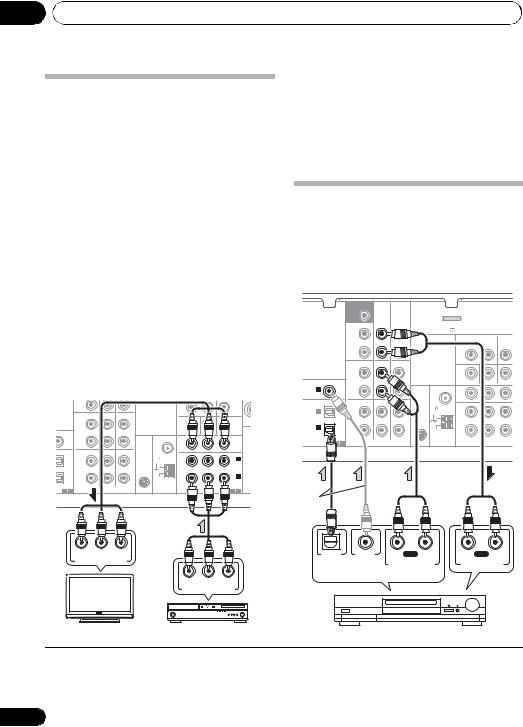
03 Connecting your equipment
Using the component video jacks
Component video should deliver superior picture quality when compared to composite video. A further advantage (if your source and TV are both compatible) is progressive-scan video, which delivers a very stable, flicker-free picture. See the manuals that came with your TV and source component to check whether they are compatible with progressive-scan video.
• If necessary, assign the component video inputs to the input source you’ve connected.
This only needs to be done if you didn’t connect according to the following defaults:
•COMPONENT VIDEO IN 1 – BD
•COMPONENT VIDEO IN 2 – DVD
See The Input Assign menu on page 46 for more on this.
•For the audio connection, refer to
Connecting your component with no HDMI terminal on page 24.
|
|
R |
|
|
|
|
|
|
|
|
|
|
PRE OUT |
CD-R/TAPE DVR/VCR |
|
|
|
|
|
|
|
|
|
CD |
|
|
|
|
|
|
||
|
|
L |
|
|
|
|
|
|
|
|
SIGNABLE |
IN |
|
IN |
|
MONITOR OUT |
DVD IN |
|
BD IN |
SPE |
|
|
|
|
|
|||||||
|
|
R |
|
|
ANTENNA |
PR |
PB |
Y |
MONITOR |
|
|
|
|
|
|
|
|
|
OUT |
||
|
|
TV/SAT |
DVD |
BD |
FM |
|
|
|
|
|
|
|
UNBAL |
|
|
|
|
|
|||
|
|
L |
|
|
75 |
|
|
|
IN 2 |
|
|
|
|
|
SIRIUS |
|
|
|
(DVD) |
||
|
|
|
|
|
IN |
|
|
|
||
|
|
IN |
|
IN |
|
|
|
|
|
|
|
|
|
|
|
|
|
|
|
||
|
|
R |
|
|
AM |
|
|
|
IN 1 |
|
|
|
|
|
|
|
|
(BD) |
|||
|
|
|
|
|
LOOP |
|
|
|
||
SIGNABLE |
|
|
|
|
|
ASSIGNABLE |
||||
|
|
|
|
|
|
|||||
1 |
2 |
|
AUDIO |
|
|
COMPONENT VIDEO |
|
1 |
2 |
|
 Important
•If you connect any source component to the receiver using a component video input, you must also have your TV connected to this receiver’s COMPONENT VIDEO OUT jacks.
Connecting other audio components
The number and kind of connections depends on the kind of component you’re connecting.1 Follow the steps below to connect a CD-R, MD, DAT, tape recorder or other audio component.
|
|
SUBWOOFER |
|
|
|
|
|
|
|
|
|
PRE OUT |
|
|
|
|
|
|
|
|
|
|
CD-R/TAPE DVR/VCR |
|
|
|
|
|
|
|
|
SURR BACK / |
|
ADAPTER PORT |
|
|
|
|
|
|
|
FRONT |
|
(OUTPUT 5 V |
100 mA MAX) |
|
|
|
|
|
|
HEIGHT |
|
|
|
|
|
|
|
|
|
L |
|
|
VIDEO |
DVR/VCR |
TV/SAT |
||
|
|
(Single) |
OUT |
|
|
||||
|
|
|
|
OUT |
IN |
|
IN |
||
|
|
|
|
|
|
||||
|
|
R |
|
|
|
|
|
|
|
|
|
PRE OUT |
|
|
|
|
|
|
|
|
|
CD |
CD-R/TAPE DVR/VCR |
|
|
|
|
|
|
|
|
L |
|
|
|
|
|
|
|
COAXIAL |
ASSIGNABLE |
IN |
|
|
MONITOR OUT |
DVD IN |
|
BD IN |
|
IN 1 |
|
R |
|
ANTENNA |
PR |
|
PB |
Y |
M |
(CD) |
|
|
|
|
|
|
|
||
|
|
|
|
|
|
|
|
||
OPTICAL |
|
TV/SAT |
DVD |
FM |
|
|
|
|
|
|
UNBAL |
|
|
|
|
|
|||
IN 2 |
|
L |
|
75 |
|
|
|
|
|
|
|
SIRIUS |
|
|
|
|
|
||
|
|
IN |
IN |
IN |
|
|
|
|
|
|
|
|
|
|
|
|
|
||
IN 1 |
|
R |
|
AM |
|
|
|
|
|
(CD-R/TAPE) |
|
|
|
|
|
|
|||
|
|
|
|
LOOP |
|
|
|
ASSIGN |
|
|
2 |
|
AUDIO |
|
COMPONENT VIDEO |
||||
|
|
|
|
|
|||||
 2
2
PR |
PB |
Y |
OPTICAL |
COAXIAL |
R PLAY L |
R REC |
L |
COMPONENT VIDEO IN |
DIGITAL AUDIO OUT |
ANALOG AUDIO OUT |
ANALOG AUDIO IN |
||||
|
|
|
|||||
|
PR PB |
Y |
Select one |
|
|
||
|
COMPONENT VIDEO OUT |
|
|
TV |
BD player |
|
CD-R, MD, DAT, Tape recorder, etc. |
 Note
Note
1Note that you must connect digital components to analog audio jacks if you want to record to/from digital components (like an MD) to/from analog components.
2If the connection was made using an optical or a coaxial cable, you’ll need to tell the receiver which digital input you connected the component to (see Choosing the input signal on page 41).
26
En
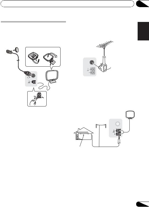
Connecting your equipment
Connecting antennas
Connect the AM loop antenna and the FM wire antenna as shown below. To improve reception and sound quality, connect external antennas (see Using external antennas below).
fig. a |
fig. b |
2
4 |
ANTENNA |
AM


 3
3
LOOP
 1
1
1Push open the tabs, then insert one wire fully into each terminal, then release the tabs to secure the AM antenna wires.
2Fix the AM loop antenna to the attached stand.
To fix the stand to the antenna, bend in the direction indicated by the arrow (fig. a) then clip the loop onto the stand (fig. b).
3Place the AM antenna on a flat surface and in a direction giving the best reception.
4Connect the FM wire antenna into the FM antenna socket.
For best results, extend the FM antenna fully and fix to a wall or door frame. Don’t drape loosely or leave coiled up.
|
|
03 |
Using external antennas |
English |
|
an external FM antenna. |
|
|
To improve FM reception |
|
|
Use an F connector (not supplied) to connect |
|
|
ANTENNA |
|
Deutsch |
FM |
F connector |
|
UNBAL |
|
|
75 Ω |
|
|
AM |
|
|
Français |
|
LOOP |
|
|
|
|
To improve AM reception |
|
|
||
Connect a 5 m to 6 m (15 ft. to 18 ft.) length of |
|
|||
vinyl-coated wire to the AM antenna terminal |
Italiano |
|||
without disconnecting the supplied AM loop |
||||
|
||||
antenna. |
|
|
|
|
For the best possible reception, suspend |
|
|||
horizontally outdoors. |
|
Nederlands |
||
|
antenna |
FM |
||
|
Outdoor |
ANTENNA |
|
|
|
|
UNBAL |
|
|
|
|
75 Ω |
Español |
|
|
|
AM |
||
|
|
LOOP |
|
|
Indoor antenna |
5 m to 6 m |
|
|
|
(vinyl-coated wire) |
(15 ft. to 18 ft.) |
|
||
27
En
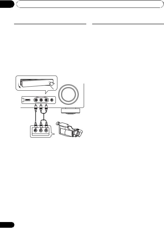
03 Connecting your equipment
Connecting to the front panel video terminal
Front video connections are accessed via the front panel using the INPUT SELECTOR or VIDEO button on the remote control. There are standard audio/video jacks. Hook them up the same way you made the rear panel connections.
•Push down on the PUSH OPEN tab to access the front video connections.
MASTER
VOLUME
VIDEO INPUT
iPod iPhone
USB |
|
MCACC |
VIDEO |
L AUDIO R |
SETUP MIC |
This receiver
VIDEO |
L |
R |
AUDIO/VIDEO OUTPUT
Video camera (etc.)
28
Plugging in the receiver
Only plug in after you have connected all your components to this receiver, including the speakers.
• Plug the AC power cord into a convenient AC power outlet.
 CAUTION
•Handle the power cord by the plug part. Do not pull out the plug by tugging the cord, and never touch the power cord when your hands are wet, as this could cause a short circuit or electric shock. Do not place the unit, a piece of furniture, or other object on the power cord or pinch the cord in any other way. Never make a knot in the cord or tie it with other cables. The power cords should be routed so that they are not likely to be stepped on. A damaged power cord can cause a fire or give you an electric shock. Check the power cord once in a while. If you find it damaged, ask your nearest Pioneer authorized independent service company for a replacement.
•The receiver should be disconnected by removing the mains plug from the wall socket when not in regular use, e.g., when on vacation.
En
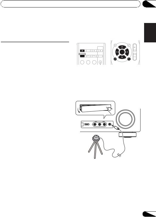
Basic Setup
Chapter 4:
Basic Setup
Automatically setting up for surround sound (MCACC)
The Auto Multi-Channel Acoustic Calibration (MCACC) setup measures the acoustic characteristics of your listening area, taking into account ambient noise, speaker size and distance, and tests for both channel delay and channel level. After you have set up the microphone provided with your system, the receiver uses the information from a series of test tones to optimize the speaker settings and equalization for your particular room.
 CAUTION
•The test tones used in the Auto MCACC Setup are output at high volume.
 Important
•The OSD will not appear if you have connected using the HDMI output to your TV. Use component or composite connections for system setup.
•The Auto MCACC Setup will overwrite any existing speaker settings you’ve made.
•Before using the Auto MCACC Setup, the iPod USB function should not be selected as an input source.
•If you connected either the surround back speaker or the front height speaker, make sure that the Pre Out setting is correctly set before performing the Auto MCACC Setup (see page 47). (Here is an explanation using the OSD screen for a surround back speaker connection.)
04
|
|
|
|
|
|
|
English |
|
|
|
|
AUDIO |
|
TUNER EDIT MASTER |
|
||
|
|
|
PARAMETER |
|
TOOLS |
VOLUME |
|
|
|
|
|
TOP |
TUNE |
MENU |
|
||
|
|
|
|
|
|
|||
|
|
|
MENU |
|
|
|
|
|
RECEIVER SLEEP |
TV |
|
|
|
|
Deutsch |
||
SOURCE CONTROL |
iPod CTRL |
|
RETURN |
|
||||
|
|
|
T |
|
P |
|
|
|
|
|
|
E |
|
R |
|
|
|
|
|
|
S |
ENTER |
E |
|
|
|
|
|
|
E |
S |
|
|
||
|
|
|
P |
|
E |
|
|
|
RECEIVER |
INPUT SELECT |
R |
|
T |
|
|
||
|
|
|
|
|||||
|
|
INPUT |
|
|
|
|
|
|
|
|
|
HOME |
U |
|
|
|
|
BD |
DVD |
TV |
MENU |
|
|
|
||
SETUP |
T NE |
BAND |
|
|||||
|
|
|
CATEGORY |
|
DTV/ TV |
MUTE |
|
|
|
|
|
|
|
|
|||
1 Switch on the receiver and your TV. |
Français |
|||||||
Switch the TV input so that it connects to the |
||||||||
|
||||||||
receiver in analog. |
|
|
|
|
|
|||
2 Connect the microphone to the MCACC |
|
|||||||
SETUP MIC jack on the front panel. |
|
|
||||||
Make sure there are no obstacles between the |
Italiano |
|||||||
speakers and the microphone. |
|
|
|
|||||
|
|
|
|
|||||
|
|
|
|
|
|
MASTER |
|
|
|
|
|
|
|
|
VOLUME |
Nederlands |
|
|
|
VIDEO INPUT |
|
|
|
|
||
|
iPod |
|
|
|
|
|
|
|
|
iPhone |
|
|
|
|
|
||
|
USB |
|
MCACC |
|
|
|
|
|
|
|
VIDEO L AUDIO R SETUP MIC |
|
|
|
|
||
Microphone |
|
|
|
|
|
Español |
||
|
|
|
|
|
|
|
||
Tripod
If you have a tripod, use it to place the microphone so that it’s about ear level at your normal listening position. Otherwise, place the microphone at ear level using a table or a chair.
29
En
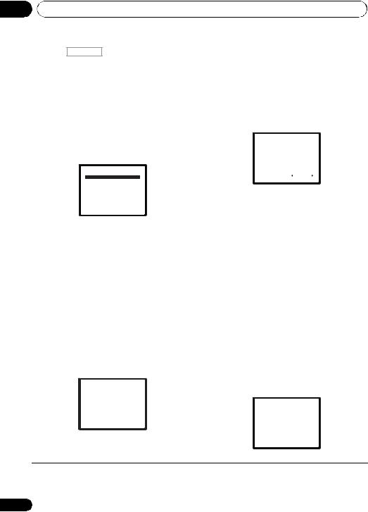
04 Basic Setup
3 Press RECEIVER on the remote control, then press the SETUP button.
An on-screen display (OSD) appears on your TV. Use / / / and ENTER on the remote
control to navigate through the screens and select menu items. Press RETURN to exit the current menu.
•Press SETUP at any time to exit the System Setup menu.1
7 Confirm the speaker configuration.
The configuration shown on-screen should reflect the actual speakers you have.
•With error messages (such as Too much ambient noise) select RETRY after checking for ambient noise (see Other problems when using the Auto MCACC Setup on page 31).
1.Auto MCACC
4 Select ‘Auto MCACC’ from the System Setup menu then press ENTER.2
System Setup
1.Auto MCACC 2.Manual SP Setup 3.Input Assign 4.Pre Out Setting
Return
Try to be as quiet as possible after pressing ENTER. The system outputs a series of test tones to establish the ambient noise level.
5Follow the instructions on-screen.
•Make sure the microphone is connected.
•Make sure the subwoofer is on and the volume is turned up.
•See below for notes regarding background noise and other possible interference.
6Wait for the test tones to finish.
A progress report is displayed on-screen while the receiver outputs test tones to determine the speakers present in your setup. Try to be as quiet as possible while it’s doing this.
1.Auto MCACC
Now Analyzing
Environment Check
Ambient Noise
Speaker YES/NO
Return
Check!
Front |
[ |
YES ] |
||
Center |
[ |
YES ] |
||
Surr |
[ |
YES ] |
||
Surr. Back |
[YESx2] |
|||
Subwoofer |
[ |
YES ] |
||
|
|
|
|
|
10:Next |
|
|
OK |
|
|
|
Return |
||
If the speaker configuration displayed isn’t correct, use / to select the speaker and / to change the setting. When you’re finished, go to the next step.
If you see an error message (ERR) in the right side column, there may be a problem with the speaker connection. If selecting RETRY doesn’t fix the problem, turn off the power and check the speaker connections.
8 Make sure ‘OK’ is selected, then press ENTER.
If the screen in step 7 is left untouched for 10 seconds and the ENTER button is not pressed in step 8, the Auto MCACC setup will start automatically as shown below.
A progress report is displayed on-screen while the receiver outputs more test tones to determine the optimum receiver settings for channel level, speaker distance, and Acoustic Calibration EQ.
1.Auto MCACC
Now Analyzing
Surround Analyzing
Speaker System
Speaker Distance
Channel Level
Acoustic Cal EQ
•For correct speaker settings, do not adjust the volume during the test tones.
Return
 Note
Note
1The screensaver automatically starts after three minutes of inactivity. If you cancel the Auto MCACC Setup at any time, the receiver automatically exits and no settings will be made.
2MIC IN blinks when the microphone is not connected to MCACC SETUP MIC.
30
En
Loading...