


AUDIO/VIDEO MULTI-CHANNEL RECEIVER
RECEPTEUR AUDIOVISUEL A VOIES MULTI-CANAUX
VSX-518
Register your product at:
www.pioneerelectronics.com (US) www.pioneerelectronics.ca (Canada)
• Protect your new investment
The details of your purchase will be on file for reference in the event of an insurance claim such as loss or theft.
•Receive free tips, updates and service bulletins on your new product
•Improve product development
Your input helps us continue to design products that meet your needs.
• Receive a free Pioneer newsletter
Registered customers can opt in to receive a monthly newsletter.
Operating Instructions
Mode d'emploi

WARNING
This equipment is not waterproof. To prevent a fire or shock hazard, do not place any container filled with liquid near this equipment (such as a vase or flower pot) or expose it to dripping, splashing, rain or moisture.
WARNING
Before plugging in for the first time, read the following section carefully.
The voltage of the available power supply differs according to country or region. Be sure that the power supply voltage of the area where this unit will be used meets the required voltage (e.g., 230 V or 120 V) written on the rear panel.
This product contains mercury. Disposal of this material may be regulated due to environmental considerations. For disposal or recycling information, please contact your local authorities or the Electronics Industries Alliance : www.eiae.org.
If the AC plug of this unit does not match the AC outlet you want to use, the plug must be removed and appropriate one fitted. Replacement and mounting of an AC plug on the power supply cord of this unit should be performed only by qualified service personnel. If connected to an AC outlet, the cut-off plug can cause severe electrical shock. Make sure it is properly disposed of after removal.
The equipment should be disconnected by removing the mains plug from the wall socket when left unused for a long period of time (for example, when on vacation).
WARNING: Handling the cord on this product or cords associated with accessories sold with the product will expose you to chemicals listed on proposition 65 known to the State of California and other governmental entities to cause cancer and birth defect or other reproductive harm.
Wash hands after handling |
D36-P4_A_En |
IMPORTANT NOTICE – THE SERIAL NUMBER FOR THIS EQUIPMENT IS LOCATED IN THE REAR.
PLEASE WRITE THIS SERIAL NUMBER ON YOUR ENCLOSED WARRANTY CARD AND KEEP IN A SECURE AREA. THIS IS FOR YOUR SECURITY.
NOTE: This equipment has been tested and found to comply with the limits for a Class B digital device, pursuant to Part 15 of the FCC Rules. These limits are designed to provide reasonable protection against harmful interference in a residential installation. This equipment generates, uses, and can radiate radio frequency energy and, if not installed and used in accordance with the instructions, may cause harmful interference to radio communications. However, there is no guarantee that interference will not occur in a particular installation. If this equipment does cause harmful interference to radio or television reception, which can be determined by turning the equipment off and on, the user is encouraged to try to correct the interference by one or more of the following measures:
–Reorient or relocate the receiving antenna.
–Increase the separation between the equipment and receiver.
–Connect the equipment into an outlet on a circuit different from that to which the receiver is connected.
– Consult the dealer or an experienced radio/TV technician for help. |
D8-10-1-2_En |
This Class B digital apparatus complies with Canadian ICES-003.
Cet appareil numérique de la Classe B est conforme à la norme NMB-003 du Canada.
D8-10-1-3_EF
Information to User
Alteration or modifications carried out without appropriate authorization may invalidate the user’s right to operate the equipment.
CAUTION: This product satisfies FCC regulations when shielded cables and connectors are used to connect the unit to other equipment. To prevent electromagnetic interference with electric appliances such as radios and televisions, use shielded cables and connectors for connections.
FEDERAL COMMUNICATIONS COMMISSION DECLARATION OF CONFORMITY
This device complies with part 15 of the FCC Rules. Operation is subject to the following two conditions: (1) This device may not cause harmful interference, and (2) this device must accept any interference received, including interference that may cause undesired operation.
Product Name: |
AUDIO/VIDEO MULTI-CHANNEL RECEIVER |
Model Number: |
VSX-518-K, VSX-518-S |
Responsible Party Name: |
PIONEER ELECTRONICS SERVICE INC. |
Address: |
1925 E. DOMINGUEZ ST. LONG BEACH, CA 90801-1760, USA |
Phone: |
1-800-421-1404 |
IMPORTANT
CAUTION
RISK OF ELECTRIC SHOCK
DO NOT OPEN
The lightning flash with arrowhead symbol, within an equilateral triangle, is intended to alert the user to the presence of uninsulated "dangerous voltage" within the product's enclosure that may be of sufficient magnitude to constitute a risk of electric shock to persons.
CAUTION:
TO PREVENT THE RISK OF ELECTRIC SHOCK, DO NOT REMOVE COVER (OR BACK). NO USER-SERVICEABLE PARTS INSIDE. REFER SERVICING TO QUALIFIED SERVICE PERSONNEL.
The exclamation point within an equilateral triangle is intended to alert the user to the presence of important operating and maintenance (servicing) instructions in the literature accompanying the appliance.
D3-4-2-1-1_En-A
1)Read these instructions.
2)Keep these instructions.
3)Heed all warnings.
4)Follow all instructions.
5)Do not use this apparatus near water.
6)Clean only with dry cloth.
7)Do not block any ventilation openings. Install in accordance with the manufacturer’s instructions.
8)Do not install near any heat sources such as radiators, heat registers, stoves, or other apparatus (including amplifiers) that produce heat.
9)Do not defeat the safety purpose of the polarized or grounding-type plug. A polarized plug has two blades with one wider than the other. A grounding type plug has two blades and a third grounding prong. The wide blade or the third prong are provided for your safety. If the provided plug does not fit into your outlet, consult an electrician for replacement of the obsolete outlet.
10)Protect the power cord from being walked on or pinched particularly at plugs, convenience receptacles, and the point where they exit from the apparatus.
11)Only use attachments/accessories specified by the manufacturer.
12)Use only with the cart, stand, tripod, bracket, or table specified by the manufacturer, or sold with the apparatus. When a cart is used, use caution when moving the cart/apparatus combination to avoid injury from tip-over.
13)Unplug this apparatus during lightning storms or when unused for long periods of time.
14)Refer all servicing to qualified service personnel. Servicing is required when the apparatus has been damaged in any way, such as power-supply cord or plug is damaged, liquid has been spilled or objects have fallen into the apparatus, the apparatus has been exposed to rain or moisture, does not operate normally, or has been dropped.
P1-4-2-2_En
WARNING
To prevent a fire hazard, do not place any naked flame sources (such as a lighted candle) on the equipment.
VENTILATION CAUTION
When installing this unit, make sure to leave space around the unit for ventilation to improve heat radiation (at least 20 cm at top, 10 cm at rear, and 30 cm at each side).
WARNING
Slots and openings in the cabinet are provided for ventilation to ensure reliable operation of the product, and to protect it from overheating. To prevent fire hazard, the openings should never be blocked or covered with items (such as newspapers, table-cloths, curtains) or by operating the equipment on thick carpet or a bed.
Operating Environment
Operating environment temperature and humidity: +5 ºC to +35 ºC (+41 ºF to +95 ºF); less than 85 %RH (cooling vents not blocked)
Do not install this unit in a poorly ventilated area, or in locations exposed to high humidity or direct sunlight (or strong artificial light)
CAUTION
The STANDBY/ON switch on this unit will not completely shut off all power from the AC outlet. Since the power cord serves as the main disconnect device for the unit, you will need to unplug it from the AC outlet to shut down all power. Therefore, make sure the unit has been installed so that the power cord can be easily unplugged from the AC outlet in case of an accident. To avoid fire hazard, the power cord should also be unplugged from the AC outlet when left unused for a long period of time (for example, when on vacation).
For U.S. and Australia Model
CAUTION
To prevent fire hazard, the
Class 2 Wiring Cable should be used for connection with speaker, and should be routed away from hazards to avoid damage to the insulation of the cable.

Thank you for buying this Pioneer product. Please read through these operating instructions so you will know how to operate your model properly. After you have finished reading the instructions, put them away in a safe place for future reference.
Contents
01 Before you start
Checking what’s in the box . . . . . . . . . . . . . . . 5
Loading the batteries . . . . . . . . . . . . . . . . . . . 5
Installing the receiver . . . . . . . . . . . . . . . . . . . 5
Ventilation . . . . . . . . . . . . . . . . . . . . . . . . . . 5
02 5 minute guide
Introduction to home theater . . . . . . . . . . . . . 6 Listening to Surround Sound . . . . . . . . . . . . . 6
Using the Quick Setup . . . . . . . . . . . . . . . . . . 7
03 Connecting up
Making cable connections . . . . . . . . . . . . . . . 8
Analog audio cables. . . . . . . . . . . . . . . . . . . 8 Digital audio cables . . . . . . . . . . . . . . . . . . . 8 Video cables . . . . . . . . . . . . . . . . . . . . . . . . . 8
Connecting a TV and DVD player . . . . . . . . . . 9 Connecting the multichannel analog
outputs. . . . . . . . . . . . . . . . . . . . . . . . . . . . 10
Connecting a satellite receiver or
other digital set-top box. . . . . . . . . . . . . . . . . 10 Connecting other audio components . . . . . . 11 About the WMA9 Pro decoder . . . . . . . . . . 11
Connecting to the front panel audio
mini jack. . . . . . . . . . . . . . . . . . . . . . . . . . . 12
Connecting other video components . . . . . . 12 Using the component video jacks. . . . . . . . 13
Connecting antennas . . . . . . . . . . . . . . . . . . 14
Using external antennas. . . . . . . . . . . . . . . 14 Connecting the speakers . . . . . . . . . . . . . . . 15 Hints on speaker placement. . . . . . . . . . . . 16 Speaker placement diagrams. . . . . . . . . . . 16
04 Controls and displays
Front panel . . . . . . . . . . . . . . . . . . . . . . . . . . 17 Display . . . . . . . . . . . . . . . . . . . . . . . . . . . . . 18 Remote control . . . . . . . . . . . . . . . . . . . . . . . 20 Direct function . . . . . . . . . . . . . . . . . . . . . . 23
Operating range of remote control unit . . . 23
05 Listening to your system
Auto playback . . . . . . . . . . . . . . . . . . . . . . . . 24
Listening in surround sound . . . . . . . . . . . . . 24 Using the Advanced surround effects . . . . 25
Listening in stereo. . . . . . . . . . . . . . . . . . . . . 25
Using Front Stage Surround Advance. . . . . . 26
Using Stream Direct . . . . . . . . . . . . . . . . . . . 26
Using the Sound Retriever . . . . . . . . . . . . . . 26
Using Phase Control . . . . . . . . . . . . . . . . . . . 27
Using Virtual Surround Back (VSB). . . . . . . . 27
Setting the AV options. . . . . . . . . . . . . . . . . . 28 Playing other sources . . . . . . . . . . . . . . . . . . 30
Choosing the input signal . . . . . . . . . . . . . . . 30 Selecting the multichannel analog inputs . . . 30
06 The System Setup menu
Using the System Setup menu . . . . . . . . . . . 31
Manual speaker setup . . . . . . . . . . . . . . . . . . 31 Speaker setting . . . . . . . . . . . . . . . . . . . . . . 31 Crossover network . . . . . . . . . . . . . . . . . . . 32 Channel level . . . . . . . . . . . . . . . . . . . . . . . 32 Speaker Distance . . . . . . . . . . . . . . . . . . . . 32
The Input Assign menu . . . . . . . . . . . . . . . . . 33
07 Using the tuner
Listening to the radio. . . . . . . . . . . . . . . . . . . 34
Improving FM stereo sound . . . . . . . . . . . . 34 Tuning directly to a station . . . . . . . . . . . . . 34 Saving station presets . . . . . . . . . . . . . . . . . . 35 Naming station presets. . . . . . . . . . . . . . . . 35 Listening to station presets . . . . . . . . . . . . . 35
08 Making recordings
Making an audio or a video recording . . . . . . 36
09 Additional information
Troubleshooting . . . . . . . . . . . . . . . . . . . . . . 37
Resetting the main unit . . . . . . . . . . . . . . . . . 38 Switching the speaker impedance. . . . . . . . . 39
Power cord caution . . . . . . . . . . . . . . . . . . . . 39 Specifications . . . . . . . . . . . . . . . . . . . . . . . . 39 Cleaning the unit . . . . . . . . . . . . . . . . . . . . 40
Manufactured under license from Dolby Laboratories. "Dolby", "Pro Logic" and the double-D symbol are trademarks
of Dolby Laboratories.
"DTS" is a registered trademark of DTS, Inc. and "DTS 96/24" is a trademark of DTS, Inc.
Before you start
Chapter 1:
Before you start
Checking what’s in the box |
Installing the receiver |
Please check that you’ve received the following supplied accessories:
•Remote control
•AA size IEC R6 dry cell batteries (to confirm system operation) x2
•AM loop antenna
•FM wire antenna
•These operating instructions
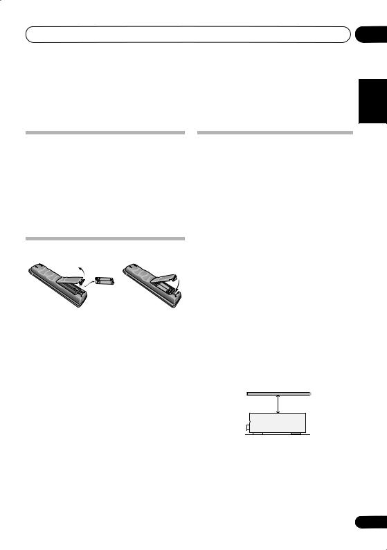
Loading the batteries
 Caution
Incorrect use of batteries may result in such hazards as leakage and bursting. Observe the following precautions:
•Never use new and old batteries together.
•Insert the plus and minus sides of the batteries properly according to the marks in the battery case.
•Batteries with the same shape may have different voltages. Do not use different batteries together.
•When disposing of used batteries, please comply with governmental regulations or environmental public instruction’s rules that apply in your country or area.
•Do not use or store batteries in direct sunlight or other excessively hot place, such as inside a car or near a heater. This can cause batteries to leak, overheat, explode or catch fire. It can also reduce the life or performance of batteries.
•When installing this unit, make sure to put it on a level and stable surface.
Don’t install it on the following places:
–on a color TV (the screen may distort)
–near a cassette deck (or close to a device that gives off a magnetic field). This may interfere with the sound.
–in direct sunlight
–in damp or wet areas
–in extremely hot or cold areas
–in places where there is vibration or other movement
–in places that are very dusty
–in places that have hot fumes or oils (such as a kitchen)
Ventilation
When installing this unit, make sure to leave space around the unit for ventilation to improve heat dispersal (at least 20 cm (8 in.) at the top). If not enough space is provided between the unit and walls or other equipment, heat will build up inside, interfering with performance and/or causing malfunctions.
20 cm (8 inches)
Receiver
Slot and openings in the cabinet are provided for ventilation and to protect the equipment from overheating. To prevent fire hazard, do not place anything directly on top of the unit, make sure the openings are never blocked or covered with items (such as newspapers, table-cloths and curtains), and do not operate the equipment on thick carpet or a bed.
01
Español Nederlands Italiano Français Deutsch English
5
En
02 5 minute guide
Chapter 2:
5 minute guide
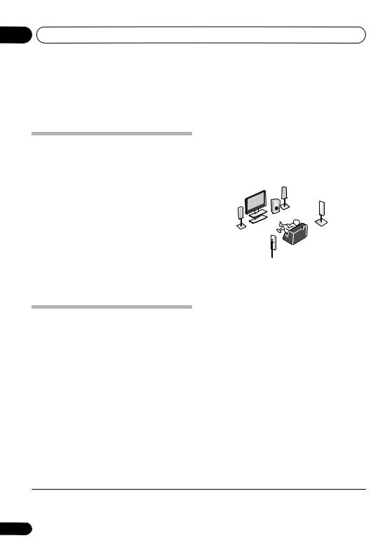
Introduction to home theater
Home theater refers to the use of multiple audio tracks to create a surround sound effect, making you feel like you’re in the middle of the action or concert. The surround sound you get from a home theater system depends not only on your speaker setup, but also on the source and the sound settings of the receiver.
This receiver will automatically decode multichannel Dolby Digital, DTS, or Dolby Surround sources according to your speaker setup. In most cases, you won’t have to make changes for realistic surround sound, but other possibilities (like listening to a CD with multichannel surround sound) are explained in
Listening to your system on page 24.
Listening to Surround Sound
This receiver was designed with the easiest possible setup in mind, so with the following quick setup guide, you should have your system hooked up for surround sound in no time at all. In most cases, you can simply leave the receiver in the default settings.
•Be sure to complete all connections before connecting to an AC power source.
1 Connect your TV and DVD player.
See Connecting a TV and DVD player on page 9 to do this. For surround sound, you’ll want to hook up using a digital connection from the DVD player to the receiver.
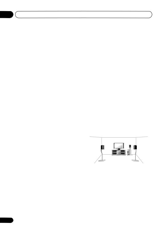
2 Connect your speakers and place them for optimal surround sound.
See Connecting the speakers on page 15.
Where you place the speakers will have a big effect on the sound. Place your speakers as shown below for the best surround sound effect. Also see Hints on speaker placement on page 16 for more on this.
Subwoofer (SW)
Front
Right (R)
Front |
Surround |
Right (RS) |
Left (L)
Center (C)
Listening
position
Surround Left (LS) 
3Plug in and switch on the receiver, followed by your DVD player, subwoofer and TV.
Make sure you’ve set the video input on your TV to this receiver. Check the manual that came with the TV if you don’t know how to do this.
4Press QUICK SETUP to specify your speaker setup, room size and listening
position.
Use / and ENTER to confirm your selection. See Using the Quick Setup below for more on this.
5Play a DVD, and adjust the volume.
Make sure that DVD/BD is showing in the receiver’s display, indicating that the DVD input is selected. If it isn’t, press DVD on the remote to set the receiver to the DVD input.
There are several other sound options you can select. See Listening to your system on page 24 for more on this.1 See also The System Setup menu on page 31 for more setup options.
 Note
Note
1Depending on your DVD player or source discs, you may only get digital 2 channel stereo and analog sound. In this case, the listening mode must be set to STANDARD (it should already be set—see Listening in surround sound on page 24 if you need to do this) if you want multichannel surround sound.
6
En

5 minute guide
Using the Quick Setup
You can use the Quick Setup to get your system up and running with just a few button presses. The receiver automatically makes the necessary settings after you have selected your speaker setup, room size and listening position.
If you want to make more specific settings, refer to The System Setup menu on page 31.
|
|
|
|
|
MASTER |
|
|
|
|
|
|
|
VOLUME |
|
|
RECEIVER |
|
|
|
RECEIVER CONTROL |
CH+ |
||
|
|
SOURCE |
ONE TOUCH |
|
|
||
|
|
|
|
|
|||
INPUT SELECT |
|
|
COPY |
|
|
|
|
|
|
|
|
|
|
||
|
|
|
|
AV |
TUNE |
|
T.EDIT |
|
|
|
|
PARAMETER |
|
|
|
MULTI CONTROL PORTABLE |
DVD 5.1 |
TOPMENU |
|
ST |
MENU |
||
DVD |
TV |
DVR |
TV CTRL |
ST |
|
|
|
|
ENTER |
|
|
||||
CD-R |
|
|
|
|
|
|
CH- |
CD |
FM |
AM |
RECEIVER |
GUIDE |
TUNE |
|
|
|
STEREO/ |
|
|
|
|
|
|
AUTO/DIRECT |
STANDARD ADVSURR |
|
|
|
|
||
A.L.C. |
SETUP |
|
RETURN |
||||
|
|
|
|
|
|||
|
QUICK |
|
SOUND |
SUBTITLE |
REC |
|
AUDIO |
PHASE |
DIALOG |
|
|
|
|
||
SETUP |
RETRIEVER |
|
|
|
|
||
1 If the receiver is off, press RECEIVER to turn the power on.
2Press RECEIVER on the remote control, then press QUICK SETUP.
3Use / to choose your subwoofer setting.
Select YES or NO, depending on whether you’ve connected a subwoofer.
4Press ENTER.
5Use / to choose your speaker setup.
If you selected YES for the subwoofer setting in step 3, the following choices are available:
2.1ch – 3.1ch – 4.1ch – 5.1ch
If you selected NO for the subwoofer setting in step 3, the following choices are available:
2.0ch – 3.0ch – 4.0ch – 5.0ch
02
• Check the table below to find the speaker |
English |
||||||||
|
setup that corresponds with your system. |
||||||||
|
|
||||||||
|
|
|
|
|
|
|
|
|
|
|
|
|
|
|
|
|
|
|
|
|
|
|
|
|
|
|
|
|
Deutsch |
|
|
|
|
|
|
|
|
|
|
|
|
|
|
|
|
|
|
|
|
|
|
|
|
|
|
|
|
|
|
|
|
|
|
|
|
|
|
|
|
|
|
|
|
|
|
|
|
|
|
|
|
|
|
|
|
|
|
|
|
|
|
|
|
|
|
|
|
|
Français |
|
|
|
|
|
|
|
|
|
|
|
|
|
|
|
|
|
|
|
|
|
|
|
|
|
|
|
|
|
|
6 |
Press ENTER. |
|
|||||||
|
|
||||||||
7 Use / to choose your room size. |
|
Italiano |
|||||||
Depending on the distance of your speakers |
|
||||||||
|
|
||||||||
from the listening position, choose between |
|
|
|||||||
small, medium, or large (S, M or L), M being |
|
|
|||||||
an average-sized room. |
|
|
|||||||
8 |
Press ENTER. |
|
Nederlands |
||||||
9 Use / to choose your listening |
|
||||||||
|
|
||||||||
position. |
|
|
|||||||
You can cycle between the following choices: |
|
|
|||||||
• FWD – If you are nearer to the front |
|
|
|||||||
• |
speakers than the surround speakers |
|
Español |
||||||
BACK – If you are nearer to the surround |
|
||||||||
• |
MID – If you are equal distance from the |
|
|
||||||
|
front and surround speakers |
|
|
||||||
|
speakers than the front speakers |
|
|
||||||
10 |
Press ENTER to confirm your setup. |
|
|
||||||
|
|
||||||||
The display shows the speaker setup, room size and listening position that you have selected.
7
En
03 Connecting up
Chapter 3:
Connecting up
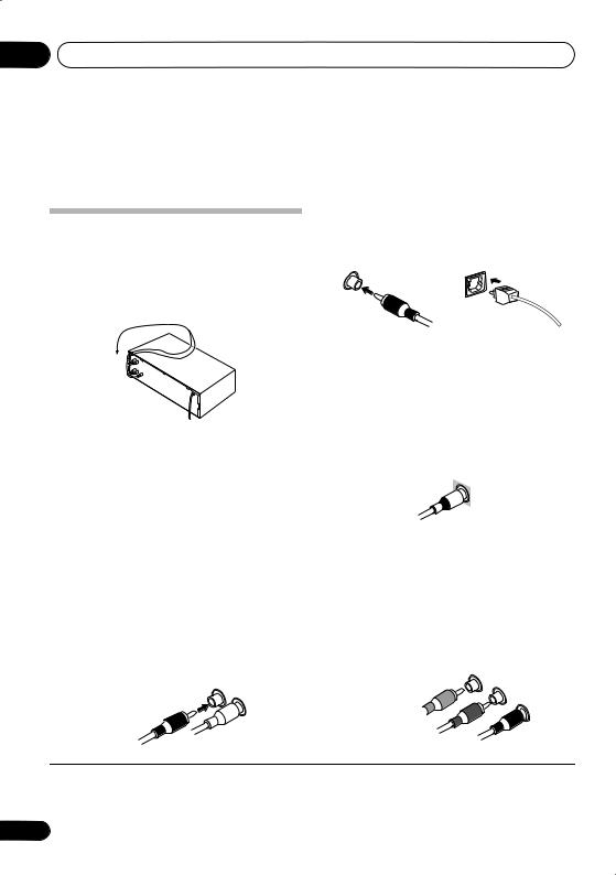
Digital audio cables
Making cable connections
Make sure not to bend the cables over the top of this unit (as shown in the illustration). If this happens, the magnetic field produced by the transformers in this unit may cause a humming noise from the speakers.
 Important
•Before making or changing any connections, switch off the power and disconnect the power cord from the AC outlet.
•Before unplugging the power cord, switch the power into standby.
Commercially available coaxial digital audio cables or optical cables should be used to connect digital components to this receiver.1
Coaxial digital audio cable |
Optical cable |
Video cables
Standard RCA video cables
These cables are the most common type of video connection and should be used to connect to the composite video terminals. They have yellow plugs to distinguish them from cables for audio.
Standard RCA video cable
Component video cables
Analog audio cables
Use stereo RCA phono cables to connect analog audio components. These cables are typically red and white, and you should connect the red plugs to R (right) terminals and white plugs to L (left) terminals.
Analog audio cables
Right (red)
Left (white)
Use component video cables to get the best possible color reproduction of your video source. The color signal of the TV is divided into the luminance (Y) signal and the color (PB and PR) signals and then output. In this way, interference between the signals is avoided.
Component video cables
Green (Y)
Blue (PB)
Red (PR)
 Note
Note
1• When connecting optical cables, be careful when inserting the plug not to damage the shutter protecting the optical socket.
•When storing optical cable, coil loosely. The cable may be damaged if bent around sharp corners.
•You can also use a standard RCA video cable for coaxial digital connections.
8
En
Connecting up |
03 |
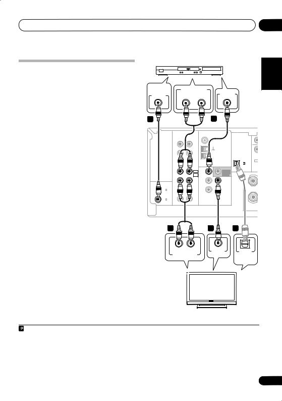
Connecting a TV and DVD player |
DVD player |
English |
|
||
|
|
|
This page shows you how to connect your DVD |
|
|
player and TV to the receiver. |
|
|
|
|
|
DIGITAL |
|
ANALOG AUDIO OUT |
|
|
|
|
|
1 Connect a coaxial digital audio output on |
AUDIO OUT |
|
VIDEO OUT |
|
|
|||||
COAXIAL |
|
R |
L |
|
|
|||||
your DVD player to the DIGITAL COAX 1 |
1 |
|
|
|
2 |
|
|
Deutsch |
||
connection.1 |
|
|
|
|
|
|
|
|||
(DVD/BD) input on this receiver. |
|
|
|
|
|
|
|
|
|
|
Use a coaxial digital audio cable for the |
|
|
|
|
|
|
|
|
||
2 Connect the composite video output and |
|
|
|
|
ANTENNA |
|
|
|
||
|
2 |
|
|
|
|
|
|
|
|
|
the stereo analog audio outputs |
on your |
|
R |
L |
|
FM UNBAL |
|
|
Français |
|
Use a standard RCA video cable |
|
and a stereo |
|
|
/ MD |
|
|
OPT |
DVD |
|
DVD player to the DVD/BD inputs on this |
|
IN |
CD |
|
|
DIGITAL IN |
|
|
||
receiver. |
3 |
|
|
IN |
CD-R |
|
|
|
R |
|
|
|
|
|
|
AM |
|
|
|
||
|
|
|
|
/TAPE |
|
|
|
|
||
|
|
|
|
|
|
|
LOOP |
|
|
|
RCA phono cable for the connection. |
|
OUT |
|
|
|
1 |
|
|
||
|
|
|
|
|
|
|
||||
|
|
|
|
|
(CD) |
|
|
|||
• If your DVD player has multichannel |
|
IN |
DVD/BD |
DVD |
SUB |
(ASSIGNABLE) |
|
|
||
|
FRONT |
|
|
|
||||||
|
|
CHINPUT |
/ BD IN |
PREOUT |
|
|
|
|||
to connect it. |
|
|
|
|
DVD5.1 |
|
|
R |
|
Italiano |
|
|
COAX |
|
/ VCR |
|
|
R |
|
||
analog outputs, see Connecting the |
(ASSIGNABLE) DIGITAL IN |
|
/ SAT |
/ SAT IN |
OUT |
S |
|
|
||
|
P |
|
|
|||||||
|
|
|
|
IN |
TV |
TV |
MONITOR |
|
|
|
multichannel analog outputs below for how |
2 |
IN |
|
DVR |
DVR |
E |
|
|
||
|
|
|
COAX |
|
|
|
|
A |
|
|
|
|
|
(DVR / VCR) |
|
DVR |
/ VCR IN |
/ VCR OUT |
K |
|
|
|
|
|
|
|
|
|
E |
|
|
|
|
|
|
|
|
|
|
|
|
|
|
|
|
|
1 |
OUT |
|
|
|
S |
|
|
3 Connect the analog audio outputs from |
(DVD / BD) |
|
AUDIO |
|
VIDEO |
|
|
|||
|
|
|
|
|
|
|||||
your TV to the TV/SAT inputs on this receiver. |
|
|
|
|
|
|
|
Nederlands |
||
This will allow you to play the sound from the |
This receiver |
|
|
|
|
|
||||
|
|
|
|
|
|
|||||
TV’s built-in tuner. Use a stereo RCA phono |
|
|
|
|
|
|
||||
3 |
|
|
|
4 |
3 |
|
|
|||
cable to do this. |
|
|
|
|
|
|
|
|||
|
|
|
|
|
|
|
|
|
|
|
• If your TV has a built-in digital decoder, you |
|
|
|
|
|
|
|
|
||
can also connect an optical digital audio |
|
R |
L |
|
VIDEO IN |
|
|
|
||
output from your TV to the DIGITAL OPT 1 |
|
|
OPTICAL |
|
Español |
|||||
|
ANALOG AUDIO OUT |
|
|
|||||||
|
|
|
DIGITAL |
|
||||||
(CD) input on this receiver. Use an optical |
|
|
|
|
|
|
||||
|
|
|
|
|
AUDIO OUT |
|
|
|||
cable for the connection.4 |
|
|
|
|
|
|
|
|
|
|
4 Connect the MONITOR OUT video jack on |
|
|
|
|
|
|
|
|
||
this receiver to a video input on your TV. |
|
|
|
|
|
|
|
|
||
Use a standard RCA video cable to connect to |
|
|
|
|
|
|
|
|
||
the composite video jack.5 |
|
|
|
|
|
|
|
|
|
|
|
|
|
|
|
TV |
|
|
|
|
|
Note |
|
|
|
|
|
|
|
|
|
|
1 If your DVD player only has an optical digital output, you can connect it to the optical input on this receiver using an optical |
|
|||||||||
cable. When you set up the receiver you’ll need to tell the receiver which input you connected the player to (see The Input |
|
|
||||||||
Assign menu on page 33). |
|
|
|
|
|
|
|
|
|
|
2 This connection will allow you to make analog recordings from your DVD player. |
|
|
|
|
|
|
||||
3 If your player also has a component video output, you can connect this too. See Using the component video jacks on page 13. |
|
|||||||||
4 In this case, you’ll need to tell the receiver which digital input you connected the TV to (see The Input Assign menu on page 33). |
|
|||||||||
5 See Using the component video jacks on page 13 if you want to use the component video outputs to connect this receiver to |
|
|||||||||
your TV. |
|
|
|
|
|
|
|
|
|
|
|
|
|
|
|
|
|
|
|
|
9 |
En

03 Connecting up
Connecting the multichannel analog outputs
For DVD Audio and SACD playback, your DVD player may have 5.1 channel analog outputs. In this case, you can connect them to the multichannel inputs of this receiver as shown below.1
This receiver
|
|
|
|
ANTENNA |
|
|
CEN- |
SUB |
|
|
|
|
|
|
|
|
TER |
WOOFER |
|
|
R |
L |
|
FM UNBAL |
|
|
|
|
|
|
IN |
CD |
|
|
DIGITAL IN |
|
|
|
|
|
IN |
|
|
|
|
R |
SURROUND |
L |
|
|
|
CD-R |
|
AM |
|
||||
|
|
/TAPE |
|
|
|
|
|
|
|
|
|
/ MD |
|
LOOP |
OPT |
DVD 5.1CH INPUT |
|
||
|
OUT |
|
|
|
|
||||
|
|
|
|
1 |
|
|
|
|
|
|
|
|
|
|
|
|
|
|
|
|
|
|
|
|
(CD) |
|
|
|
|
|
IN |
DVD/BD |
DVD |
SUB |
(ASSIGNABLE) |
|
|
|
M |
|
FRONT |
|
|
|
|
||||
|
|
DVD5.1 |
/ BD IN |
WOOFER |
R |
|
FRONT |
|
L R |
|
|
|
PREOUT |
|
|
|
|||
|
|
CHINPUT |
|
S |
|
|
|
|
|
|
|
TV |
TV |
MONITOR |
|
|
|
|
|
|
IN |
P |
|
|
|
|
|||
(ASSIGNABLE) DIGITAL IN |
|
/ SAT |
/ SAT IN |
OUT |
|
|
|
|
|
|
|
|
|
E |
|
|
|
|
|
|
|
|
|
|
|
|
|
|
|
COAX |
IN |
|
DVR |
DVR |
A |
|
|
|
|
2 |
|
K |
|
|
|
|
|||
(DVR / VCR) |
|
|
/VCR IN |
/ VCR OUT |
|
|
|
|
|
|
|
DVR |
|
|
E |
|
|
|
|
|
|
/VCR |
|
|
|
|
|
|
|
COAX |
OUT |
|
|
|
R |
|
|
|
|
1 |
|
|
|
S |
|
|
|
|
|
(DVD / BD) |
|
AUDIO |
|
VIDEO |
|
|
|
|
|
|
|
|
|
|
|
|
|
||
VIDEO |
R |
L |
CENTER |
R |
L |
SUB- |
OUTPUT |
|
FRONT |
OUTPUT |
SURROUND |
WOOFER |
|
|
OUTPUT |
|
OUTPUT |
OUTPUT |
||
DVD/multi-channel decoder with multi-channel analog output jacks
Connecting a satellite receiver or other digital set-top box
Satellite and cable receivers, and terrestrial digital TV tuners are all examples of so-called ‘set-top boxes’.
1Connect a set of audio/video outputs on
the set-top box component to the TV/SAT AUDIO and VIDEO inputs on this receiver.2
Use a stereo RCA phono cable for the audio
connection and a standard RCA video cable for the video connection.3
2If your set-top box has a digital output, connect it to a digital input on this receiver.
The example shows an optical connection to the DIGITAL OPT 1 (CD) input.4
|
|
|
|
|
ANTENNA |
|
|
|
R |
|
L |
|
FM UNBAL |
|
|
|
IN |
|
CD |
|
|
DIGITAL IN |
|
|
|
|
|
|
|
||
|
IN |
|
|
|
|
|
|
|
|
|
CD-R |
|
AM |
|
|
|
|
|
/TAPE |
|
|
|
|
|
|
|
|
LOOP |
|
|
|
|
|
|
/ MD |
|
|
OPT |
|
|
OUT |
|
|
|
|
|
|
|
|
|
|
|
|
1 |
|
|
|
|
|
|
|
|
|
|
|
|
|
|
|
|
(CD) |
|
|
|
DVD/BD |
DVD |
|
(ASSIGNABLE) |
|
|
IN |
|
FRONT |
|
SUB |
|
|
|
|
|
DVD5.1 |
/ BD IN |
|
WOOFER |
R |
|
|
|
|
|
PREOUT |
||
|
|
|
CHINPUT |
|
|
S |
|
|
|
|
TV |
TV |
|
MONITOR |
|
|
IN |
|
|
P |
|||
(ASSIGNABLE) DIGITAL IN |
|
|
/ SAT |
/ SAT IN |
|
OUT |
|
|
|
|
|
|
|
E |
|
|
|
|
|
|
|
|
|
COAX |
IN |
|
|
DVR |
|
DVR |
A |
2 |
|
|
|
K |
|||
|
|
/ VCR IN |
|
/ VCR OUT |
|||
(DVR / VCR) |
|
|
DVR |
|
|||
|
|
|
|
|
|
E |
|
|
|
|
/ VCR |
|
|
|
|
COAX |
OUT |
|
|
|
|
|
R |
1 |
|
|
|
|
|
S |
|
(DVD / BD) |
|
AUDIO |
|
VIDEO |
|
||
|
|
|
|
|
|||
This receiver |
|
1 |
|
|
2 |
|
|
|
|
|
|
|
|
||
|
R |
AUDIO |
L |
|
VIDEO |
COAXIAL |
OPTICAL |
|
|
|
AUDIO/VIDEO OUT |
|
DIGITAL OUT |
||
|
STB |
|
|
|
|
|
|
 Note
Note
1The multichannel input can only be used when DVD 5.1ch is selected (see page 30).
2If you’ve already connected your TV to the TV/SAT inputs, simply choose another input. However, you’ll need to remember which input you connected the set-top box to.
3See Using the component video jacks on page 13 if your set-top box also has a component video output.
4In this case, you’ll need to tell the receiver which digital input you connected the set-top box to (see The Input Assign menu on page 33).
10
En
Connecting up |
03 |
Connecting other audio components
The number and kind of connections depends on the kind of component you’re connecting.1 Follow the steps below to connect a CD-R, MD, DAT, tape recorder or other audio component.
1If your component has a digital output, connect this to a digital input on the receiver.
The example shows an optical connection to the DIGITAL OPT 1 (CD) input.
2If necessary, connect the analog audio outputs of the component to a set of spare audio inputs on this receiver.
You’ll need to make this connection for components without a digital output, or if you want to record from a digital component. Use a stereo RCA phono cable as shown.
3If you’re connecting a recorder, connect the analog audio outputs to the analog audio inputs on the recorder.
The example shows an analog connection to the CD-R/TAPE/MD analog output jack using a stereo RCA phono cable.
This receiver
|
|
|
|
|
|
ANTENNA |
|
|
|
|
R |
L |
|
|
FM UNBAL |
|
|
|
IN |
|
CD |
|
|
|
DIGITAL IN |
|
|
|
|
|
|
|
|
||
|
IN |
|
|
|
|
|
|
|
|
|
|
CD-R |
|
|
AM |
|
|
|
|
|
/TAPE |
|
|
|
|
|
|
|
|
/ MD |
|
|
LOOP |
|
OPT |
|
OUT |
|
|
|
|
|
|
|
|
|
|
|
|
|
|
1 |
|
|
|
|
|
|
|
|
|
|
|
|
|
|
|
|
|
|
(CD) |
|
|
|
DVD/BD |
DVD |
|
|
(ASSIGNABLE) |
|
|
IN |
|
FRONT |
|
|
SUB |
|
|
|
|
|
DVD5.1 |
/ BD IN |
|
WOOFER |
R |
|
|
|
|
|
|
|
PREOUT |
||
|
|
|
CHINPUT |
|
|
|
S |
|
|
|
|
TV |
TV |
|
|
MONITOR |
|
|
IN |
|
|
|
P |
|||
(ASSIGNABLE) DIGITAL IN |
|
|
/ SAT |
/ SAT IN |
|
OUT |
||
|
|
|
|
|
|
|
E |
|
|
|
|
|
|
|
|
|
|
COAX |
IN |
|
|
DVR |
|
|
DVR |
A |
2 |
|
|
/ VCR IN |
|
/ VCR OUT |
K |
||
(DVR / VCR) |
|
|
DVR |
|
||||
|
|
|
|
|
|
|
E |
|
|
|
|
/ VCR |
|
|
|
|
|
COAX |
OUT |
|
|
|
|
|
|
R |
1 |
|
|
|
|
|
|
S |
|
(DVD / BD) |
|
|
AUDIO |
|
|
VIDEO |
|
|
|
|
|
|
|
|
|
||
3 |
|
|
2 |
|
|
|
1 |
|
R |
IN |
L |
|
R |
OUT |
L |
COAXIAL |
OPTICAL |
|
REC |
|
|
|
PLAY |
|
DIGITAL OUT |
|
|
AUDIO IN |
|
|
AUDIO OUT |
||||
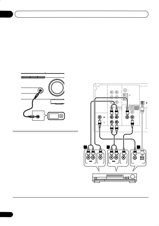
CD-R, MD, DAT, Tape recorder, etc.
About the WMA9 Pro decoder
This unit has an on-board Windows Media® Audio 9 Professional (WMA9 Pro) decoder, so it is possible to playback WMA9 Pro-encoded audio using a coaxial or optical digital connection when connected to a WMA9 Procompatible player. However, the connected DVD player, set-top box, etc. must be able to output WMA9 Pro format audio signals through a coaxial or optical digital output.
Español Nederlands Italiano Français Deutsch English
 Note
Note
1Note that you must connect digital components to analog audio jacks if you want to record to/from digital components (like an MD) to/from analog components.
11
En
03 Connecting up
Windows Media and the Windows logo are trademarks or registered trademarks of Microsoft Corporation in the United States and/or other countries.
Connecting to the front panel audio mini jack
Front audio connections are accessed via the front panel using the PORTABLE button. Use a stereo mini-jack cable to connect a digital audio player, etc.
AM |
PORTABLE |
SLEEP |
PORTABLE
AUDIO OUT
Digital audio player, etc.
Connecting other video components
This receiver has audio/video inputs and outputs suitable for connecting analog or digital video recorders, including VCRs and HDD/DVD recorders.
1 Connect a set of audio/video outputs on the recorder to the DVR/VCR AUDIO and VIDEO inputs on this receiver.
Use a stereo RCA phono cable for the audio connection and a standard RCA video cable for the video connection.
2Connect a set of audio/video inputs on the recorder to the DVR/VCR AUDIO and VIDEO outputs on this receiver.
Use a stereo RCA phono cable for the audio connection and a standard RCA video cable for the video connection.
3If your video component has a digital audio output, connect it to a digital input on this receiver.
The example shows a recorder connected to the DIGITAL COAX 2 (DVR/VCR) input.1
This receiver
|
|
|
|
ANTENNA |
|
|
R |
L |
|
FM UNBAL |
|
|
IN |
CD |
|
|
DIGITAL IN |
|
|
|
|
||
|
IN |
|
|
|
|
|
|
CD-R |
|
AM |
|
|
|
/TAPE |
|
|
|
|
|
/ MD |
|
LOOP |
OPT |
|
OUT |
|
|
|
|
|
|
|
|
1 |
|
|
|
|
|
|
|
|
|
|
|
|
(CD) |
|
IN |
DVD/BD |
DVD |
SUB |
(ASSIGNABLE) |
|
FRONT |
|
|||
|
|
DVD5.1 |
/ BD IN |
WOOFER |
|
|
|
|
PREOUT |
|
|
|
|
CHINPUT |
|
S |
|
|
|
TV |
TV |
MONITOR |
|
|
IN |
P |
|||
(ASSIGNABLE) DIGITAL IN |
|
/ SAT |
/ SAT IN |
OUT |
|
|
|
|
|
E |
|
|
|
|
|
|
|
COAX |
IN |
|
DVR |
DVR |
A |
2 |
|
/ VCR IN |
/ VCR OUT |
K |
|
(DVR / VCR) |
|
DVR |
|||
|
|
|
|
E |
|
|
|
/ VCR |
|
|
|
COAX |
OUT |
|
|
|
R |
1 |
|
|
|
S |
|
(DVD / BD) |
|
AUDIO |
|
VIDEO |
|
|
|
|
|
1 |
|
|
2 |
|
|
|
|
3 |
R |
OUT |
L |
|
R |
IN |
L |
COAXIAL |
OPTICAL |
PLAY |
|
REC |
||||||
AUDIO OUT |
VIDEO OUT |
|
AUDIO IN |
VIDEO IN |
DIGITAL OUT |
|||
DVR, VCR, LD player, etc.
 Note
Note
1If your video component only has an optical digital output, you can connect it to the optical input on this receiver using an optical cable. When you set up the receiver you’ll need to tell the receiver which input you connected the component to (see
The Input Assign menu on page 33).
12
En

Connecting up
Using the component video jacks
Component video should deliver superior picture quality when compared to composite video. A further advantage (if your source and TV are both compatible) is progressive-scan video, which delivers a very stable, flicker-free picture. See the manuals that came with your TV and source component to check whether they are progressive-scan video compatible.
 Important
•If you connect any source component to the receiver using a component video input, you must also have your TV connected to this receiver’s COMPONENT VIDEO MONITOR OUT jacks.
1Connect the component video outputs of your source to a set of component video inputs on this receiver.
Use a three-way component video cable.
2If necessary, assign the component video inputs to the input source you’ve connected.
This only needs to be done if you didn’t connect according to the following defaults:
•COMP 1 – DVD
•COMP 2 – TV
•COMP 3 – DVR
See Assigning the component video inputs on page 33.
3 Connect the COMPONENT VIDEO MONITOR OUT jacks on this receiver to the component video inputs on your TV or monitor.
Use a three-way component video cable.
03
Español Nederlands Italiano Français Deutsch English
13
En
03 Connecting up
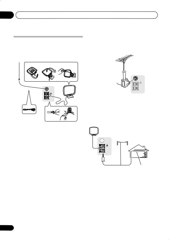
Connecting antennas
Connect the AM loop antenna and the FM wire antenna as shown below. To improve reception and sound quality, connect external antennas (see Using external antennas below).
fig. a |
fig. b |
fig. c |
Using external antennas
To improve FM reception
Use an F connector to connect an external FM antenna.
3
FM UNBAL
5 |
75 Ω |
AM
LOOP
4
1
2 |
1Pull off the protective shields of both AM antenna wires.
2Push open the tabs, then insert one wire fully into each terminal, then release the tabs to secure the AM antenna wires.
3Fix the AM loop antenna to the attached stand.
To fix the stand to the antenna, bend in the direction indicated by the arrow (fig. a) then clip the loop onto the stand (fig. b).
•If you plan to mount the AM antenna to a wall or other surface, secure the stand with screws (fig. c) before clipping the loop to the stand. Make sure the reception is clear.
4Place the AM antenna on a flat surface and in a direction giving the best reception.
5Connect the FM wire antenna in the same way as the AM loop antenna.
For best results, extend the FM antenna fully and fix to a wall or door frame. Don’t drape loosely or leave coiled up.
FM UNBAL
75 Ω
F connector
AM
LOOP
To improve AM reception
Connect a 5 m to 6 m (15 ft. to 18 ft.) length of vinyl-coated wire to the AM antenna terminal without disconnecting the supplied AM loop antenna.
For the best possible reception, suspend horizontally outdoors.
|
Outdoor |
|
FM UNBAL |
antenna |
|
75 Ω |
|
|
AM |
|
|
LOOP |
|
|
5 m to 6 m |
Indoor antenna |
|
(15 ft. to 18 ft.) |
(vinyl-coated wire) |
|
14
En
Connecting up |
03 |
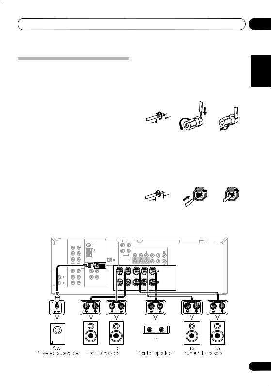
Connecting the speakers
A complete setup of six speakers (including the subwoofer) is shown below, but everyone’s home setup will vary. Simply connect the speakers you have in the manner shown below. The receiver will work with just two stereo speakers (the front speakers in the diagram) but using at least three speakers is recommended, and a complete setup is best for surround sound. If you’re not using a subwoofer, change the front speaker setting (see Speaker setting on page 31) to LARGE.
Make sure you connect the speaker on the right to the right terminal and the speaker on the left to the left terminal. Also make sure the positive and negative (+/–) terminals on the receiver match those on the speakers. You can use speakers with a nominal impedance between 6 Ω to 16 Ω (please see Switching the speaker impedance on page 39 if you plan to use speakers with an impedance of less than 8 Ω).
Be sure to complete all connections before connecting this unit to the AC power source.
Bare wire connections
Front speaker terminals:
1Twist exposed wire strands together.
2Loosen terminal and insert exposed wire.
3Tighten terminal.
1 |
2 |
3 |
10 mm (3/8 in.)
Center and surround speaker terminals:
1Twist exposed wire strands together.
2Push open the tabs and insert exposed wire.
3Release the tabs.
1 |
2 |
3 |
10 mm (3/8 in.)
|
|
|
|
ANTENNA |
|
|
CEN- |
SUB |
|
|
|
|
|
|
|
|
|
|
|
|
|
|
|
TER |
WOOFER |
|
|
|
|
|
|
|
|
|
R |
L |
|
FM UNBAL |
|
|
|
|
|
|
|
|
|
|
|
|
|
IN |
CD |
|
|
DIGITAL IN |
|
|
|
|
|
|
|
|
|
|
|
|
|
|
|
|
|
|
|
|
|
|
|
|
|
|
||
|
|
|
|
|
|
|
|
|
|
|
|
|
(ASSIGNABLE) |
|
|
|
|
IN |
|
|
|
|
|
|
|
|
|
(DVR / VCR) IN 3 |
|
(DVD / BD) IN 1 |
|||
|
|
|
|
|
R |
SURROUND |
L |
|
|
|
|
|
|
|
||
|
|
CD-R |
|
AM |
|
|
|
|
|
|
|
|
||||
|
|
/TAPE |
|
|
|
|
|
|
|
|
|
|
|
|
|
|
|
|
/ MD |
|
LOOP |
OPT |
DVD 5.1CH INPUT |
|
Y |
PB |
|
PR |
Y |
PB |
PR |
||
|
OUT |
|
|
|
|
|
||||||||||
|
|
|
|
1 |
|
|
|
|
|
|
|
|
|
|
|
|
|
|
|
|
|
(CD) |
|
|
|
|
|
|
|
|
|
|
|
|
IN |
DVD/BD |
DVD |
SUB |
(ASSIGNABLE) |
|
|
|
MONITOR OUT |
|
COMPONENT VIDEO |
(TV / SAT) IN 2 |
||||
|
FRONT |
|
|
|
|
|
||||||||||
|
|
DVD5.1 |
/ BD IN |
WOOFER |
|
R |
FRONT |
|
L R |
SURROUND |
L |
CENTER |
|
|
||
|
|
CHINPUT |
|
PREOUT |
S |
|
|
|
|
|
|
|
|
|
|
|
|
|
TV |
TV |
MONITOR |
|
|
|
|
|
|
|
|
|
|
|
|
|
IN |
P |
|
|
|
|
|
|
|
|
|
|
|
|||
(ASSIGNABLE) DIGITAL IN |
|
/ SAT |
/ SAT IN |
OUT |
|
|
|
|
|
|
|
|
|
|
|
|
|
|
|
|
E |
|
|
|
|
|
|
|
|
|
|
|
|
|
|
|
|
|
|
|
|
|
|
|
|
|
|
|
|
|
COAX |
IN |
|
DVR |
DVR |
A |
|
|
|
|
|
|
|
|
|
|
|
2 |
|
K |
|
|
|
|
|
|
|
|
|
|
|
|||
(DVR / VCR) |
|
DVR |
/ VCR IN |
/ VCR OUT |
|
|
|
|
|
|
|
|
|
|
|
|
|
|
|
|
E |
|
|
|
|
|
|
|
|
|
|
|
|
|
|
/ VCR |
|
|
|
|
|
|
|
|
|
|
|
|
|
|
COAX |
OUT |
|
|
|
R |
|
|
|
|
|
|
|
|
|
|
|
1 |
|
|
|
S |
|
|
|
|
|
|
|
|
|
|
|
|
(DVD / BD) |
|
AUDIO |
|
VIDEO |
|
|
|
|
|
|
|
|
|
|
|
|
|
|
|
|
|
|
|
|
|
|
|
|
|
|
|
||
Español Nederlands Italiano Français Deutsch English
15
En
03 Connecting up
 Caution
•These speaker terminals carry
HAZARDOUS LIVE voltage. To prevent the risk of electric shock when connecting or disconnecting the speaker cables, disconnect the power cord before touching any uninsulated parts.
•Make sure that all the bare speaker wire is twisted together and inserted fully into the speaker terminal. If any of the bare speaker wire touches the back panel it may cause the power to cut off as a safety measure.
Hints on speaker placement
Speakers are usually designed with a particular placement in mind. Some are designed to be floorstanding, while others should be placed on stands to sound their best. Some should be placed near a wall; others should be placed away from walls. We have provided a few tips on getting the best sound from your speakers (following), but you should also follow the guidelines on placement that the speaker manufacturer provided with your particular speakers to get the most out of them.
•Place the front left and right speakers at equal distances from the TV.
•When placing speakers near the TV, we recommend using magnetically shielded speakers to prevent possible interference, such as discoloration of the picture when the TV is switched on. If you do not have magnetically shielded speakers and notice discoloration of the TV picture, move the speakers farther away from the TV.
•Place the center speaker above or below the TV so that the sound of the center channel is localized at the TV screen.
•If possible, place the surround speakers slightly above ear level.
16
•Try not to place the surround speakers further away from the listening position than the front and center speakers. Doing so can weaken the surround sound effect.
•To achieve the best possible surround sound, install your speakers as shown below. Be sure all speakers are installed securely to prevent accidents and improve sound quality.
 Caution
•If you choose to install the center speaker on top of the TV, be sure to secure it with putty, or by other suitable means, to reduce the risk of damage or injury resulting from the speaker falling from the TV in the event of external shocks such as earthquakes.
•Make sure no exposed speaker wire is touching the rear panel, this may cause the receiver to turn off automatically.
Speaker placement diagrams
The following illustrations show 5.1 channel speaker setups.
3-D view of 5.1 channel speaker setup
Overhead view of speaker setup
Front |
|
Front |
left |
Center |
right |
|
|
Subwoofer |
Surround |
|
Surround |
left |
|
right |
Listening position
En
Controls and displays
Chapter 4:
Controls and displays
04
English
Front panel
1 |
2 |
3 |
4 |
5 |
6 |
|
|
|
|
|
|
|
AUDIO/VIDEO MULTI-CHANNEL RECEIVER VSX-518 |
||
|
|
|
|
|
PHASE |
DIALOGUE |
AUTO SURR/ |
|
|
|
PHASE |
|
CONTROL |
ENHANCEMENT |
STREAM DIRECT |
|
|
|
|
|
|
|
|
|
STANDBY/ON |
|
CONTROL |
|
|
|
|
|
|
|
|
STEREO / |
|
ADVANCED |
|
|
|
|
|
|
STANDARD |
||
|
|
|
|
|
A.L.C. |
SURROUND |
|
DVD DVD 5.1 TV DVR CD CD-R FM AM PORTABLE SLEEP
INPUT |
MASTER |
SELECTOR |
VOLUME |
Français Deutsch
PHONES |
SOUND |
MIDNIGHT/ |
SIGNAL |
|
RETRIEVER |
VSB MODE LOUDNESS |
SELECT |
|
|
|
PORTABLE |
8 |
|
9 |
10 |
|
7 |
|
|
|
|
|
|
|
|||
|
|
|
|
|
15 |
16 |
17 |
PHONES |
SOUND |
|
MIDNIGHT/ |
SIGNAL |
PHASE |
DIALOGUE |
AUTO SURR/ |
|
RETRIEVER |
VSB MODE |
LOUDNESS |
SELECT |
CONTROL |
ENHANCEMENT STREAM DIRECT |
|
|
|
|
|
|
STEREO / |
STANDARD |
ADVANCED |
|
|
|
|
|
A.L.C. |
SURROUND |
|
|
11 |
12 |
13 |
14 |
|
|
|
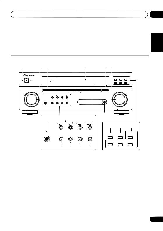
1STANDBY/ON
2INPUT SELECTOR dial
Selects an input source.
3Input select buttons
Selects an input source.
4Character display
See Display on page 18.
5SLEEP
Press to change the amount of time before the receiver switches into standby (30 min – 60 min
– 90 min – Off). You can check the remaining sleep time at any time by pressing SLEEP once.
6MASTER VOLUME dial
7PORTABLE audio input jack
Connect an auxiliary component using a stereo mini-jack cable (page 12).
8 PHONES jack
Use to connect headphones (when connected, there is no sound output from the speakers).
9 ST +/–
Use to select preset radio stations (page 35).
10 TUNE +/–
Used to find radio frequencies (page 34).
Español Nederlands Italiano
17
En
04 Controls and displays
11 SOUND RETRIEVER
Press to restore CD quality sound to compressed audio sources (page 26).
12 VSB MODE
Press to switch on/off Virtual Surround Back (VSB) mode (page 27).
13 MIDNIGHT/LOUDNESS
Switches to Midnight/Loudness listening (page 28).
14 SIGNAL SELECT
Selects an input signal (page 30).
15 PHASE CONTROL
Press to switch on/off Phase Control (page 27).
16 DIALOGUE ENHANCEMENT
Use to make dialog stand out when watching TV or a movie (page 29).
17Listening mode buttons
AUTO SURR/STREAM DIRECT
Switches between Auto surround mode (Auto playback on page 24) and Stream Direct playback. Stream Direct playback bypasses the tone controls for the most accurate reproduction of a source (page 26).
STEREO/A.L.C.
Switches between stereo playback, Auto level control stereo mode (page 25) and Front Stage Surround Advance modes (page 26).
STANDARD
Press for Standard decoding and to switch between the various 2Pro Logic II options (page 24).
ADVANCED SURROUND
Switches between the various surround modes (page 25).
Display
1 |
2 |
3 |
4 |
5 |
6 |
7 |
8 |
9 |
10 |
11 |
SP A |
12 |
13 14 |
15 |
16 |
17 |
18 |
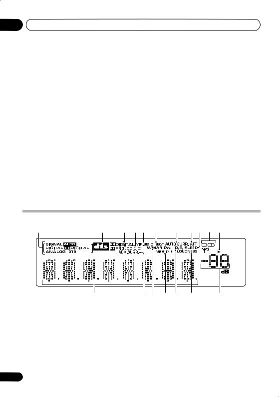
1 SIGNAL SELECT indicators |
2 DIGITAL |
|
|
||
Lights to indicate the type of input signal |
Lights when a Dolby Digital encoded signal |
||||
assigned for the current component: |
is detected. |
|
|
||
AUTO |
ANALOG |
|
|
||
Lights when AUTO signal select is on. |
Lights when an analog signal is detected. |
||||
DIGITAL |
DTS |
|
|
|
|
Lights when a digital audio signal is |
Lights when a source with DTS encoded |
||||
detected. |
audio signals is detected. |
||||
18
En

Controls and displays |
04 |
2
Lights to indicate decoding of a DTS multichannel signal.
3 2 DIGITAL
Lights to indicate decoding of a Dolby Digital multichannel signal.
4 2 PRO LOGIC II
Lights to indicate Pro Logic II decoding (see
Listening in surround sound on page 24 for more on this).
5 VIR.SB
Lights during Virtual surround back processing (page 27).
6 DIRECT
Lights when source Stream Direct playback is in use. Direct playback bypasses the tone controls for the most accurate reproduction of a source.
7 AUTO SURR.
Lights when the Auto Surround feature is switched on (see Auto playback on page 24).
8 ATT
Lights when ANALOG ATT is used to attenuate (reduce) the level of the analog input signal (page 22).
9 SLEEP
Lights when the receiver is in sleep mode (page 22).
10Tuner indicators
 / MONO
Lights when the mono mode is set using the MPX button.
 / STEREO
Lights when a stereo FM broadcast is being received in auto stereo mode.


 / TUNED
Lights when a broadcast is being received.
11 Speaker indicator
Shows if the speaker system is on or not.
SP A means the speakers are switched on.
SP means the headphones are connected.
12Character display
13ADV.SURR. (Advanced Surround)
Lights when one of the Advanced Surround modes has been selected.
14WMA9 Pro
Lights to indicate decoding of a WMA9 Pro signal.
15 MIDNIGHT
Lights during Midnight listening (page 28).
16 D.E.
Lights when Dialog Enhancement is switched on (page 29).
17 LOUDNESS
Lights during Loudness listening (page 28).
18 Master volume level
Español Nederlands Italiano Français Deutsch English
19
En
04 Controls and displays
Remote control |
|
|
1 |
|
11 |
|
|
|
|
RECEIVER |
SOURCE |
2 |
INPUT SELECT |
12 |
|
||
|
MULTI CONTROL |
PORTABLE |
DVD 5.1 |
|
||
3 |
DVD |
TV |
DVR |
TV CTRL |
|
|
CD-R |
|
|
|
13 |
||
|
CD |
FM |
AM |
RECEIVER |
||
|
AUTO/DIRECT |
STEREO/ |
STANDARD |
ADVSURR |
|
|
|
A.L.C. |
|
||||
|
PHASE |
QUICK |
DIALOG |
SOUND |
|
|
4 |
SETUP |
RETRIEVER |
|
|||
|
CH SEL |
LEVEL |
|
|||
|
|
|
||||
|
MUTE |
|
|
|
|
|
|
|
MASTER |
|
|
||
|
|
VOLUME |
|
|
||
|
|
RECEIVER CONTROL |
CH+ |
|
||
|
ONE TOUCH |
|
|
|||
5 |
|
|
|
|||
COPY |
|
|
|
|
||
AV |
TUNE |
|
|
|||
|
T.EDIT |
|
||||
|
PARAMETER |
|
|
|
||
|
TOPMENU |
|
|
MENU |
|
|
6 |
ST |
ST |
|
|||
|
ENTER |
|
|
|||
|
GUIDE |
TUNE |
CH- |
|
||
|
|
|
|
|||
|
SETUP |
RETURN |
|
|||
|
SUBTITLE |
REC |
AUDIO |
|
||
7 |
HDD |
DVD |
RECSTOP |
JUKEBOX |
|
|
|
TUNERDISP |
CLASS |
MPX |
D.ACCESS |
|
|
|
|
|
|
ENTER |
|
|
|
|
|
|
DISC |
|
|
8 |
MIDNIGHT |
ANALOGATT |
DIMMER |
SLEEP |
|
|
SIGNAL SEL |
|
|
+10 |
|
||
|
|
|
|
|
||
9 |
INFO |
TV CONTROL |
|
|||
SHIFT |
INPUT |
TV CH |
TV VOL |
14 |
||
|
||||||
|
SELECT |
|||||
10
RECEIVER
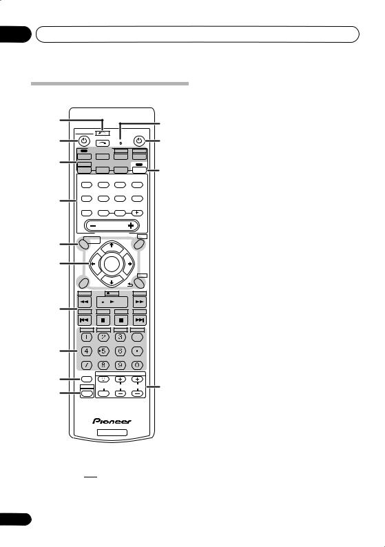
1 INPUT SELECT
Use to select the input source (use SHIFT for
INPUT SELECT 

 ).
).
2 RECEIVER
Switches the receiver between standby and on.
20
3 MULTI CONTROL buttons
Press to select control of other components (see
Direct function on page 23).
PORTABLE, DVD 5.1 and CD-R buttons can be used with SHIFT button.
4RECEIVER CONTROL buttons
AUTO/DIRECT
Switches between Auto surround mode (Auto playback on page 24) and Stream Direct playback. Stream Direct playback bypasses the tone controls for the most accurate reproduction of a source (page 26).
STEREO/A.L.C.
Switches between stereo playback, Auto level control stereo mode (page 25) and Front Stage Surround Advance modes (page 26).
STANDARD
Press for Standard decoding and to switch between 2 Pro Logic II options (page 24).
ADV SURR
Switches between the various surround modes (page 25).
PHASE
Press to switch on/off Phase Control (page 27).
QUICK SETUP
See Using the Quick Setup on page 7.
DIALOG
Use to make dialog stand out when watching TV or a movie (page 29).
SOUND RETRIEVER
Press to restore CD quality sound to compressed audio sources (page 26).
MUTE
Mutes/unmutes the sound.
CH SEL
Press repeatedly to select a channel, then use LEVEL +/– to adjust the level (page 32).
En
Controls and displays |
04 |
LEVEL +/–
Use to adjust the channel levels.
MASTER VOLUME +/–
Use to set the listening volume.
5 System Setup and Component control buttons
The following button controls can be accessed after you have selected the corresponding
MULTI CONTROL button (DVD, DVR, RECEIVER, etc.).
AV PARAMETER
Use to access the AV options.
TOP MENU
Displays the disc ‘top’ menu of a DVD.
ONE TOUCH COPY*
Copies the currently playing title from DVD to HDD or vice-versa.
GUIDE
Displays/changes the subtitles on multilingual DVDs.
SETUP
Press to access the System Setup menu (page 31). Also functions as the SETUP button for DVD/DVR units.
T.EDIT
Memorizes/names stations for recall (page 35).
MENU
Displays the disc menu of DVD-Video discs.
RETURN
Confirm and exit the current menu screen.
CH +/–*
Use to select channels for DVD/DVR units.
6 (TUNE/, ST/), ENTER
Use the arrow buttons when setting up your surround sound system (page 31). Also used to control DVD menus/options.
Use the TUNE/ buttons can be used to find radio frequencies (page 34) and the ST/ buttons can be used to select preset radio stations (page 35).
7 Component control buttons
Use these buttons to control a Pioneer DVD player or recorder connected to your system. These buttons can be accessed after the DVD or DVR button is pressed.
Button What it does
Starts/resumes normal playback.
Pauses/unpauses a disc.
Stops playback.
/Press to start fast reverse/forward scanning.
Skips to the start of the current track or chapter, then previous tracks/ chapters.
Skips to the next track or chapter.
REC* Starts recording.
REC STOP* Stops recording.
SUBTITLE* Displays/changes the subtitles on multilingual DVD-Video discs.
AUDIO* Changes the audio language or channel on DVD discs.
HDD*, Switch between the hard disk and DVD* DVD controls for DVR.
JUKEBOX* Display the jukebox screen.
Español Nederlands Italiano Français Deutsch English
21
En

04 Controls and displays
8 Number buttons and other component controls
Use the number buttons to directly select a radio frequency (page 34) or the tracks on a Pioneer DVD/DVR units. There are other buttons that can be accessed after the RECEIVER button is pressed. (For example
MIDNIGHT, etc.)
TUNER DISP*
Switches between named station presets and radio frequencies (page 35).
CLASS*
Switches between the three banks (classes) of radio station presets (page 35).
MPX*
Switches between stereo and mono reception of FM broadcasts. If the signal is weak then switching to mono will improve the sound quality (page 34).
D.ACCESS*
After pressing, you can access a radio station directly using the number buttons (page 34).
MIDNIGHT
Switches to Midnight or Loudness listening (page 28).
ANALOG ATT
Attenuates (lowers) the level of an analog input signal to prevent distortion.
DIMMER
Dims or brightens the display.
SLEEP
Press to change the amount of time before the receiver switches into standby (30 min
– 60 min – 90 min – Off). You can check the remaining sleep time at any time by pressing SLEEP once.
SIGNAL SEL
Use to select an input signal (page 30).
9 INFO
Displays additional EPG information on a DVD/ DVR.
10 SHIFT
Press to access the ‘boxed’ commands (above the buttons) on the remote. These buttons are marked with an asterisk (* ) in this section.
11 Remote control LED
Lights when a command is sent from the remote control.
12 SOURCE
Turns on or off the power of the Pioneer DVD/ DVR units when DVD or DVR is selected using the MULTI CONTROL buttons.
13 RECEIVER
Switches the remote to control the receiver (used to select the green commands above the number buttons (SETUP, etc)). Also use this button to set up surround sound (page 31).
14 TV CONTROL buttons
These buttons can control only be used with Pioneer flat panel TVs.
Use to turn on/off the power of the TV.
INPUT SELECT
Use to select the TV input signal.
TV CH +/–
Use to select channels.
TV VOL +/–
Use to adjust the volume on your TV.
22
En
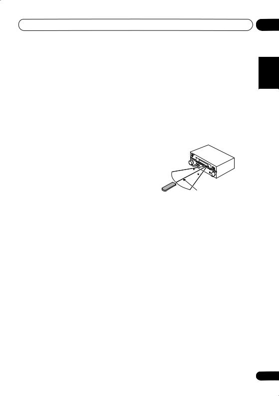
Controls and displays |
04 |
Direct function
• Default setting: ON
You can use the direct function feature to control one component using the remote control while at the same time, using your receiver to playback a different component. When direct function is on, any component you select (using the MULTI CONTROL buttons) will be selected by both the receiver and the remote control. When you turn direct function off, you can operate the remote control without affecting the receiver.
1While pressing the RECEIVER button, press and hold the 4 button.
The LED blinks.
2Press the MULTI CONTROL button for the component you want to control.
The LED lights on continuously.
3Use the number buttons to enter either
1(direct on) or 2 (direct off).
The LED blinks again.
4Repeat steps 2 through 3 for the other components you want to control.
5When you’re done, press RECEIVER.
Operating range of remote control unit
The remote control may not work properly if:
•There are obstacles between the remote control and the receiver’s remote sensor.
•Direct sunlight or fluorescent light is shining onto the remote sensor.
•The receiver is located near a device that is emitting infrared rays.
•The receiver is operated simultaneously with another infrared remote control unit.
30 

 30
30 

7 m (23 ft.)
Español Nederlands Italiano Français Deutsch English
23
En
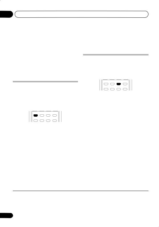
05 Listening to your system
Chapter 5:
Listening to your system
 Important
•Certain features explained in this section will not be possible depending on the source (for example, PCM 88.2 kHz/96 kHz, DTS 96 kHz (24 bit) or WMA9 Pro sources).
Listening in surround sound
Using this receiver, you can listen to any source in surround sound. However, the options available will depend on your speaker setup and the type of source you’re listening to.
Auto playback
The simplest, most direct listening option is the Auto Surround feature. With this, the receiver automatically detects what kind of source you’re playing and selects multichannel or stereo playback as necessary.1
AUTO/DIRECT |
STEREO/ |
STANDARD |
ADVSURR |
A.L.C. |
|||
PHASE |
QUICK |
DIALOG |
SOUND |
SETUP |
RETRIEVER |
• While listening to a source, press AUTO/DIRECT2 for auto playback of a source.
Press repeatedly until AUTOSURR. shows briefly in the display (it will then show the decoding or playback format). Check the digital format indicators in the display to see how the source is being processed.
AUTO/DIRECT |
STEREO/ |
STANDARD |
ADVSURR |
A.L.C. |
|||
PHASE |
QUICK |
DIALOG |
SOUND |
SETUP |
RETRIEVER |
• While listening to a source, press STANDARD.
If the source is Dolby Digital, DTS, or Dolby Surround encoded, the proper decoding format will automatically be selected and shows in the display.
With two channel sources, press STANDARD repeatedly to select from:
•2Pro Logic II MOVIE – Up to 5.1 channel sound, especially suited to movie sources
•2 Pro Logic II MUSIC3 – Up to 5.1 channel sound, especially suited to music sources
•2 Pro Logic II GAME – Up to 5.1 channel sound, especially suited for video games
•2 PRO LOGIC – 4.1 channel surround sound
 Note
Note
1• Stereo surround (matrix) formats are decoded accordingly using 2 Pro Logic II MOVIE (see Listening in surround sound above for more on these decoding formats).
• The Auto Surround feature is canceled if you connect headphones or select the multichannel analog inputs.
2For more options using this button, see Using Stream Direct on page 26.
3When listening to 2-channel sources in Dolby Pro Logic II Music mode, there are three further parameters you can adjust: Center Width, Dimension, and Panorama. See Setting the AV options on page 28 to adjust them.
24
En
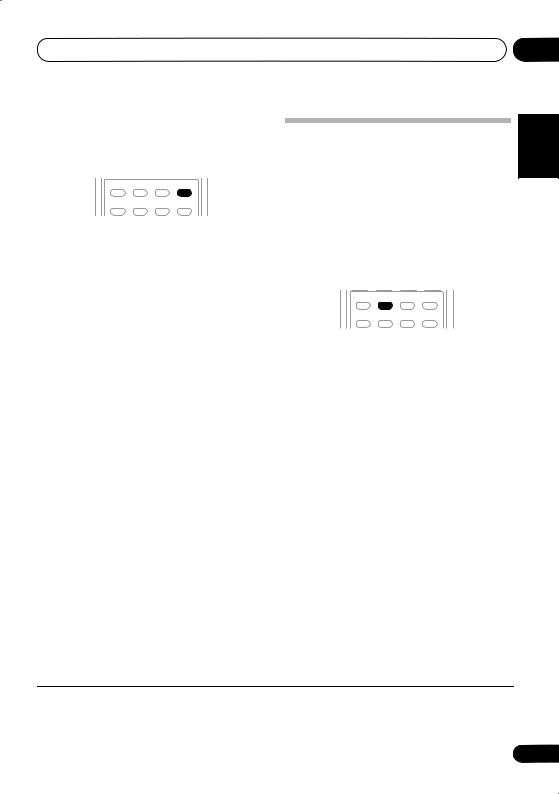
Listening to your system |
05 |
Using the Advanced surround effects
The Advanced surround feature creates a variety of surround effects. Try different modes with various soundtracks to see which you like.1
AUTO/DIRECT |
STEREO/ |
STANDARD |
ADVSURR |
A.L.C. |
|||
PHASE |
QUICK |
DIALOG |
SOUND |
SETUP |
RETRIEVER |
• Press ADV SURR repeatedly to select a listening mode.
•ACTION – Designed for action movies with dynamic soundtracks.
•DRAMA – Designed for movies with lots of dialog.
•MONOFILM – Creates surround sound from mono soundtracks.
•ENT.SHOW – Suitable for musical sources.
•EXPANDED – Creates an extra wide stereo field.2
•TV SURR. – Provides surround sound for both mono and stereo TV sources.
•ADV.GAME – Suitable for video games.
•SPORTS – Suitable for sports programs.
•ROCK/POP – Creates a live concert sound for rock and/or pop music.
•UNPLUGED – Suitable for acoustic music sources.
•X-STEREO – Gives multichannel sound to a stereo source, using all of your speakers.
•PHONESUR. – Creates the effect of overall surround with headphones.
Listening in stereo
When you select STEREO you will hear the source through just the front left and right speakers (and possibly your subwoofer depending on your speaker settings). Dolby Digital and DTS multichannel sources are downmixed to stereo.
In the Auto level control stereo mode (A.L.C.), this unit equalizes playback sound levels if each sound level varies with the music source recorded in a portable audio player.
AUTO/DIRECT |
STEREO/ |
STANDARD |
ADVSURR |
A.L.C. |
|||
PHASE |
QUICK |
DIALOG |
SOUND |
SETUP |
RETRIEVER |
• While listening to a source, press STEREO/A.L.C. for stereo playback.
Press repeatedly to switch between:
•STEREO – The audio is heard with your surround settings and you can still use the Midnight, Loudness, and Tone functions.
•A.L.C. – Listening in Auto level control stereo mode.
•F.S.S.FOCUS – See Using Front Stage Surround Advance on page 26 for more on this.
•F.S.S. WIDE – See Using Front Stage Surround Advance on page 26 for more on this.
Español Nederlands Italiano Français Deutsch English
 Note
Note
1 • If you press ADV SURR with the headphones connected, PHONESUR. will automatically be selected.
• When an Advanced Surround listening mode is selected, the effect level can be adjusted using the EFFECT parameter in
Setting the AV options on page 28.
2 Use with Dolby Pro Logic for a stereo surround effect (stereo field is wider than Standard modes with Dolby Digital sources).
25
En
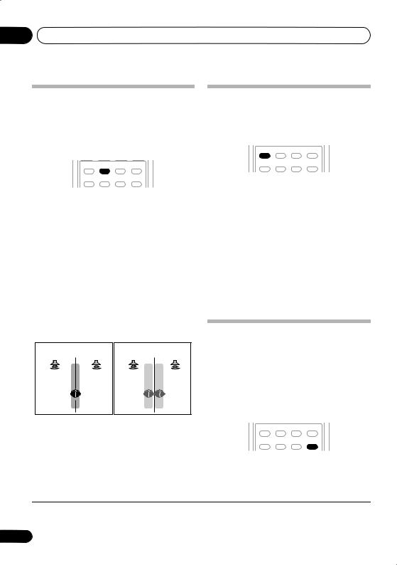
05 Listening to your system
Using Front Stage Surround Advance
The Front Stage Surround Advance function allows you to create natural surround sound effects using just the front speakers and the subwoofer.
AUTO/DIRECT |
STEREO/ |
STANDARD |
ADVSURR |
A.L.C. |
|||
PHASE |
QUICK |
DIALOG |
SOUND |
SETUP |
RETRIEVER |
• While listening to a source, press STEREO/ A.L.C. to select Front Stage Surround Advance modes.
•STEREO – See Listening in stereo on page 25 for more on this.
•A.L.C. – See Listening in stereo on page 25 for more on this.
•F.S.S.FOCUS – Use to provide a rich surround sound effect directed to the center of where the front left and right speakers sound projection area converges.
•F.S.S. WIDE – Use to provide a surround
sound effect to a wider area than FOCUS mode.1
FOCUS position (Recommend) |
WIDE position |
||
Front left |
Front right |
Front left |
Front right |
speaker |
speaker |
speaker |
speaker |
Using Stream Direct
Use the Stream Direct modes when you want to hear the truest possible reproduction of a source. All unnecessary signal processing is bypassed.
AUTO/DIRECT |
STEREO/ |
STANDARD |
ADVSURR |
A.L.C. |
|||
PHASE |
QUICK |
DIALOG |
SOUND |
SETUP |
RETRIEVER |
• While listening to a source, press AUTO/ DIRECT to select Stream Direct mode.
•AUTOSURR. – See Auto playback on page 24.
•DIRECT – Sources are heard according to the settings made in the Surround Setup (speaker setting, channel level, speaker distance), as well as with dual mono settings. You will hear sources according to the number of channels in the signal. For analog sources, only Channel Level can be set. All other digital processing can not be set.
Using the Sound Retriever
When audio data is removed during the compression process, sound quality often suffers from an uneven sound image. The Sound Retriever feature employs new DSP technology that helps bring CD quality sound back to compressed 2-channel audio by restoring sound pressure and smoothing jagged artifacts left over after compression.2
AUTO/DIRECT |
STEREO/ |
STANDARD |
ADVSURR |
A.L.C. |
|||
PHASE |
QUICK |
DIALOG |
SOUND |
SETUP |
RETRIEVER |
• Press SOUND RETRIEVER to switch the sound retriever on or off.
 Note
Note
1When using F.S.S. WIDE, a better effect can be obtained if Quick Setup is performed (see Using the Quick Setup on page 7).
2The Sound Retriever is only applicable to 2-channel sources.
26
En
 Loading...