


AUDIO/VIDEO MULTI-CHANNEL RECEIVER
RECEPTEUR AUDIOVISUEL A VOIES MULTIPLES
VSX-415 VSX-515
Register your product at:
www.pioneerelectronics.com
• Protect your new investment
The details of your purchase will be on file for reference in the event of an insurance claim such as loss or theft.
•Receive free tips, updates and service bulletins on your new product
•Improve product development
Your input helps us continue to design products that meet your needs.
• Receive a free Pioneer newsletter
Registered customers can opt in to receive a monthly newsletter.
Operating Instructions Mode d'emploi
Thank you for buying this Pioneer product.
Please read through these operating instructions so you will know how to operate your model properly. After you have finished reading the instructions, put them away in a safe place for future reference.
If the AC plug of this unit does not match the AC outlet you want to use, the plug must be removed and appropriate one fitted. Replacement and mounting of an AC plug on the power supply cord of this unit should be performed only by qualified service personnel. If connected to an AC outlet, the cut-off plug can cause severe electrical shock. Make sure it is properly disposed of after removal.
The equipment should be disconnected by removing the mains plug from the wall socket when left unused for a long period of time (for example, when on vacation).
WARNING – TO PREVENT FIRE OR SHOCK HAZARD, DO NOT EXPOSE THIS APPLIANCE TO RAIN OR MOISTURE.
D1-4-2-1_En
CAUTION – PREVENT ELECTRIC SHOCK DO NOT USE THIS (POLARIZED) PLUG WITH AN EXTENSION CORD. RECEPTACLE OR OTHER OUTLET UNLESS THE BLADES CAN BE FULLY INSERTED TO PREVENT BLADE EXPOSURE.
ATTENTION – POUR PREVENIR LES CHOCS ELECTRIQUES NE PAS UTILISER CETTE FICHE POLARISEE AVEC UN PROLONGATEUR UNE PRISE DE COURANT OU UNE AUTRE SORTIE DE COURANT, SAUF SI LES LAMES PEUVENT ETRE INSEREES A FOND SANS EN LAISSER AUCUNE PARTIE A DECOUVVERT.
WARNING: Handling the cord on this product or cords associated with accessories sold with the product will expose you to lead, a chemical known to the State of California and other governmental entities to cause cancer and birth defects or other reproductive harm.
Wash hands after handling |
D36-P4_En |
IMPORTANT NOTICE – THE SERIAL NUMBER FOR THIS EQUIPMENT IS LOCATED IN THE REAR.
PLEASE WRITE THIS SERIAL NUMBER ON YOUR ENCLOSED WARRANTY CARD AND KEEP IN A SECURE AREA. THIS IS FOR YOUR SECURITY.
NOTE: This equipment has been tested and found to comply with the limits for a Class B digital device, pursuant to Part 15 of the FCC Rules. These limits are designed to provide reasonable protection against harmful interference in a residential installation. This equipment generates, uses, and can radiate radio frequency energy and, if not installed and used in accordance with the instructions, may cause harmful interference to radio communications. However, there is no guarantee that interference will not occur in a particular installation. If this equipment does cause harmful interference to radio or television reception, which can be determined by turning the equipment off and on, the user is encouraged to try to correct the interference by one or more of the following measures:
–Reorient or relocate the receiving antenna.
–Increase the separation between the equipment and receiver.
–Connect the equipment into an outlet on a circuit different from that to which the receiver is connected.
– Consult the dealer or an experienced radio/TV technician for help. |
D8-10-1-2_En |
This Class B digital apparatus complies with Canadian ICES-003.
Cet appareil numérique de la Classe B est conforme à la norme NMB-003 du Canada.
D8-10-1-3_EF
Information to User
Alteration or modifications carried out without appropriate authorization may invalidate the user’s right to operate
the equipment. |
D8-10-2_En |
CAUTION: This product satisfies FCC regulations when shielded cables and connectors are used to connect the unit to other equipment. To prevent electromagnetic interference with electric appliances such as radios and televisions, use shielded cables and connectors for connections.
Manufactured under license from Dolby Laboratories. "Dolby", "Pro Logic", "Surround EX", and the double-D symbol are trademarks of Dolby Laboratories.
"DTS" ,"DTS-ES Extended Surround" and "Neo:6" are trademarks of Digital Theater Systems, Inc.
For U.S. and Australia Model
C67-7-3_En
CAUTION
The lightning flash with arrowhead, within an equilateral triangle, is intended to alert the user to the presence of uninsulated "dangerous voltage" within the product's enclosure that may be of sufficient magnitude to constitute a risk of electric shock to persons.
RISK OF ELECTRIC SHOCK
DO NOT OPEN
CAUTION:
TO PREVENT THE RISK OF ELECTRIC SHOCK, DO NOT REMOVE COVER (OR BACK). NO USER-SERVICEABLE PARTS INSIDE. REFER SERVICING TO QUALIFIED SERVICE PERSONNEL.
The exclamation point within an equilateral triangle is intended to alert the user to the presence of important operating and maintenance (servicing) instructions in the literature accompanying the appliance.
D1-4-2-3_En
READ INSTRUCTIONS — All the safety and operating instructions should be read before the product is operated.
RETAIN INSTRUCTIONS — The safety and operating instructions should be retained for future reference.
HEED WARNINGS — All warnings on the product and in the operating instructions should be adhered to.
FOLLOW INSTRUCTIONS — All operating and use instructions should be followed.
CLEANING — The product should be cleaned only with a polishing cloth or a soft dry cloth. Never clean with furniture wax, benzine, insecticides or other volatile liquids since they may corrode the cabinet.
ATTACHMENTS — Do not use attachments not recommended by the product manufacturer as they may cause hazards.
WATER AND MOISTURE — Do not use this product near water — for example, near a bathtub, wash bowl, kitchen sink, or laundry tub; in a wet basement; or near a swimming pool; and the like.
ACCESSORIES — Do not place this product on an unstable cart, stand, tripod, bracket, or table. The product may fall, causing serious injury to a child or adult, and serious damage to the product. Use only with a cart, stand, tripod, bracket, or table recommended by the manufacturer, or sold with the product. Any mounting of the product should follow the manufacturer’s instructions, and should use a mounting accessory recommended by the manufacturer.
CART — A product and cart combination should be moved with care. Quick stops, excessive force, and uneven surfaces may cause the product and cart combination to overturn.
VENTILATION — Slots and openings in the cabinet are provided for ventilation and to ensure reliable operation of the product and to protect it from overheating, and these openings must not be blocked or covered. The openings should never be blocked by placing the product on a bed, sofa, rug, or other similar surface. This product should not be placed in a built-in installation such as a bookcase or rack unless proper ventilation is provided or the manufacturer’s instructions have been adhered to.
POWER SOURCES — This product should be operated only from the type of power source indicated on the marking label. If you are not sure of the type of power supply to your home, consult your product dealer or local power company.
LOCATION – The appliance should be installed in a stable location.
NONUSE PERIODS – The power cord of the appliance should be unplugged from the outlet when left un-used for a long period of time.
GROUNDING OR POLARIZATION |
OBJECT AND LIQUID ENTRY — Never push |
• If this product is equipped with a polarized |
objects of any kind into this product through |
alternating current line plug (a plug having one |
openings as they may touch dangerous voltage |
blade wider than the other), it will fit into the |
points or short-out parts that could result in a |
outlet only one way. This is a safety feature. If |
fire or electric shock. Never spill liquid of any |
you are unable to insert the plug fully into the |
kind on the product. |
outlet, try reversing the plug. If the plug should |
SERVICING — Do not attempt to service this |
still fail to fit, contact your electrician to replace |
product yourself as opening or removing covers |
your obsolete outlet. Do not defeat the safety |
may expose you to dangerous voltage or other |
purpose of the polarized plug. |
hazards. Refer all servicing to qualified service |
• If this product is equipped with a three-wire |
personnel. |
grounding type plug, a plug having a third |
DAMAGE REQUIRING SERVICE — Unplug this |
(grounding) pin, it will only fit into a grounding |
product from the wall outlet and refer servicing |
type power outlet. This is a safety feature. If you |
to qualified service personnel under the |
are unable to insert the plug into the outlet, |
following conditions: |
contact your electrician to replace your obsolete |
• When the power-supply cord or plug is |
outlet. Do not defeat the safety purpose of the |
damaged. |
grounding type plug. |
• If liquid has been spilled, or objects have fallen |
POWER-CORD PROTECTION — Power-supply |
into the product. |
cords should be routed so that they are not likely |
• If the product has been exposed to rain or water. |
to be walked on or pinched by items placed |
• If the product does not operate normally by |
upon or against them, paying particular |
following the operating instructions. Adjust only |
attention to cords at plugs, convenience |
those controls that are covered by the operating |
receptacles, and the point where they exit from |
instructions as an improper adjustment of other |
the product. |
controls may result in damage and will often |
OUTDOOR ANTENNA GROUNDING — If an |
require extensive work by a qualified technician |
outside antenna or cable system is connected to |
to restore the product to its normal operation. |
the product, be sure the antenna or cable |
• If the product has been dropped or damaged in |
system is grounded so as to provide some |
any way. |
protection against voltage surges and built-up |
• When the product exhibits a distinct change in |
static charges. Article 810 of the National |
performance — this indicates a need for service. |
Electrical Code, ANSI/NFPA 70, provides |
REPLACEMENT PARTS — When replacement parts |
information with regard to proper grounding of |
are required, be sure the service technician has |
the mast and supporting structure, grounding of |
used replacement parts specified by the |
the lead-in wire to an antenna discharge unit, |
manufacturer or have the same characteristics |
size of grounding conductors, location of |
as the original part. Unauthorized substitutions |
antenna-discharge unit, connection to |
may result in fire, electric shock, or other |
grounding electrodes, and requirements for the |
hazards. |
grounding electrode. See Figure A. |
SAFETY CHECK — Upon completion of any service |
LIGHTNING — For added protection for this |
or repairs to this product, ask the service |
product during a lightning storm, or when it is |
technician to perform safety checks to |
left unattended and unused for long periods of |
determine that the product is in proper |
time, unplug it from the wall outlet and |
operating condition. |
disconnect the antenna or cable system. This |
WALL OR CEILING MOUNTING — The product |
will prevent damage to the product due to |
should not be mounted to a wall or ceiling. |
lightning and power-line surges. |
HEAT — The product should be situated away from |
POWER LINES — An outside antenna system |
heat sources such as radiators, heat registers, |
should not be located in the vicinity of overhead |
stoves, or other products (including amplifiers) |
power lines or other electric light or power |
that produce heat. |
circuits, or where it can fall into such power |
|
lines or circuits. When installing an outside |
|
antenna system, extreme care should be taken |
|
to keep from touching such power lines or |
|
circuits as contact with them might be fatal. |
|
OVERLOADING — Do not overload wall outlets, |
|
extension cords, or integral convenience |
|
receptacles as this can result in a risk of fire or |
ANTENNA |
electric shock. |
|
|
LEAD IN |
|
WIRE |
|
GROUND |
|
CLAMP |
|
ANTENNA |
|
DISCHARGE UNIT |
|
(NEC SECTION 810-20) |
ELECTRIC |
|
SERVICE |
GROUNDING CONDUCTORS |
EQUIPMENT |
(NEC SECTION 810-21) |
|
GROUND CLAMPS |
Fig. A |
POWER SERVICE GROUNDING |
ELECTRODE SYSTEM |
|
|
(NEC ART 250, PART H) |
|
NEC — NATIONAL ELECTRICAL CODE |
|
D1-4-2-2_En |

Contents
01 Before you start
Checking what’s in the box . . . . . . . . . . . . . . . 5
Loading the batteries . . . . . . . . . . . . . . . . . . . 5
Operating range of remote control unit. . . . . . 5 Installing the receiver . . . . . . . . . . . . . . . . . . . 5
02 5 minute guide
Introduction to home theater . . . . . . . . . . . . . 6 Listening to Surround Sound . . . . . . . . . . . . . 7
Using the Quick Setup . . . . . . . . . . . . . . . . . 10
03 Connecting up
Making cable connections . . . . . . . . . . . . . . 12
Analog audio cables. . . . . . . . . . . . . . . . . . 12 Digital audio cables . . . . . . . . . . . . . . . . . . 12 Video cables . . . . . . . . . . . . . . . . . . . . . . . . 12
Connecting a DVD player and TV . . . . . . . . . 13 Connecting the multichannel analog
outputs. . . . . . . . . . . . . . . . . . . . . . . . . . . . 14
Connecting a satellite receiver or other
digital set-top box . . . . . . . . . . . . . . . . . . . . . 14
Connecting other audio components . . . . . . 15 About the WMA9 Pro decoder . . . . . . . . . . 15 Connecting other video components . . . . . . 16 Using the component video jacks. . . . . . . . 16
Connecting antennas . . . . . . . . . . . . . . . . . . 18 FM wire antenna. . . . . . . . . . . . . . . . . . . . . 18 AM loop antenna . . . . . . . . . . . . . . . . . . . . 18
Using external antennas. . . . . . . . . . . . . . . 18 Connecting the speakers (VSX-415) . . . . . . . 19 Connecting the speakers (VSX-515) . . . . . . . 20
Speaker terminals . . . . . . . . . . . . . . . . . . . 21
Hints on speaker placement. . . . . . . . . . . . 21 Speaker placement diagrams. . . . . . . . . . . 21
AC outlet. . . . . . . . . . . . . . . . . . . . . . . . . . . . 22
04 Controls and displays
Front panel . . . . . . . . . . . . . . . . . . . . . . . . . . 23 Display . . . . . . . . . . . . . . . . . . . . . . . . . . . . . 25 VSX-515 model: . . . . . . . . . . . . . . . . . . . . . 25 VSX-415 model: . . . . . . . . . . . . . . . . . . . . . 25 Remote control . . . . . . . . . . . . . . . . . . . . . . . 27
05 Listening to your system
Auto playback . . . . . . . . . . . . . . . . . . . . . . . . 29
Listening in surround sound . . . . . . . . . . . . . 29 Using the Advanced surround effects . . . . 30
Listening in stereo. . . . . . . . . . . . . . . . . . . . . 32
Choosing the input signal . . . . . . . . . . . . . . . 32 Using the surround back channel
(Extended mode). . . . . . . . . . . . . . . . . . . . . . 33
Using the Virtual Surround Back mode
(VSB). . . . . . . . . . . . . . . . . . . . . . . . . . . . . . . 34
Using Midnight and Loudness listening . . . . 35
Enhancing dialog . . . . . . . . . . . . . . . . . . . . . 35
Using the tone controls . . . . . . . . . . . . . . . . . 35
Playing other sources . . . . . . . . . . . . . . . . . . 36
Selecting the multichannel analog inputs . . . 36
Using the sleep timer . . . . . . . . . . . . . . . . . . 36
06 Setting up the receiver
Choosing your receiver setup . . . . . . . . . . . . 37 Surround and sound setup options . . . . . . . . 38
Speaker setting . . . . . . . . . . . . . . . . . . . . . . 38 Subwoofer setting. . . . . . . . . . . . . . . . . . . . 38
Crossover frequency setting . . . . . . . . . . . . 38 LFE attenuator setting. . . . . . . . . . . . . . . . . 38 Front speaker distance setting . . . . . . . . . . 39 Center speaker distance setting . . . . . . . . . 39 Surround speaker distance setting . . . . . . . 39 Subwoofer distance setting. . . . . . . . . . . . . 39
Dynamic range control setting . . . . . . . . . . 39
Dual mono setting . . . . . . . . . . . . . . . . . . . 39
Digital input settings. . . . . . . . . . . . . . . . . . 40 Setting separate channel levels for
listening modes. . . . . . . . . . . . . . . . . . . . . . . 40
07 The System Setup menu
Making receiver settings from the System Setup menu. . . . . . . . . . . . . . . . . . . . . . . . . . . . . . . 41 Manual speaker setup . . . . . . . . . . . . . . . . . . 41 Speaker setting . . . . . . . . . . . . . . . . . . . . . . 42 Crossover network . . . . . . . . . . . . . . . . . . . 43 Channel level . . . . . . . . . . . . . . . . . . . . . . . 43 Speaker Distance . . . . . . . . . . . . . . . . . . . . 43 The Input Assign menu . . . . . . . . . . . . . . . . . 44 The Other setup menu. . . . . . . . . . . . . . . . . . 45
Dynamic Range Control Setup . . . . . . . . . . 45
Dual Mono Setup . . . . . . . . . . . . . . . . . . . . 45 LFE Attenuator Setup . . . . . . . . . . . . . . . . . 45
08 Using the tuner
Listening to the radio. . . . . . . . . . . . . . . . . . . 46
Improving FM stereo sound . . . . . . . . . . . . 46 Saving station presets . . . . . . . . . . . . . . . . . . 46 Naming station presets. . . . . . . . . . . . . . . . 47 Listening to station presets . . . . . . . . . . . . . 47
09 Making recordings
Making an audio or a video recording . . . . . . 48
10 Additional information
Troubleshooting . . . . . . . . . . . . . . . . . . . . . . 49
Resetting the main unit . . . . . . . . . . . . . . . . . 51 Switching the speaker impedance. . . . . . . . . 51
Specifications . . . . . . . . . . . . . . . . . . . . . . . . 52 Power cord caution . . . . . . . . . . . . . . . . . . . . 53 Cleaning the unit. . . . . . . . . . . . . . . . . . . . . . 53
Before you start
Chapter 1:
Before you start
Checking what’s in the box
Please check that you've received the following supplied accessories:
•AM loop antenna
•FM wire antenna
•Dry cell batteries (AA size IEC R6) x2
•Remote control
•These operating instructions
•Warranty card
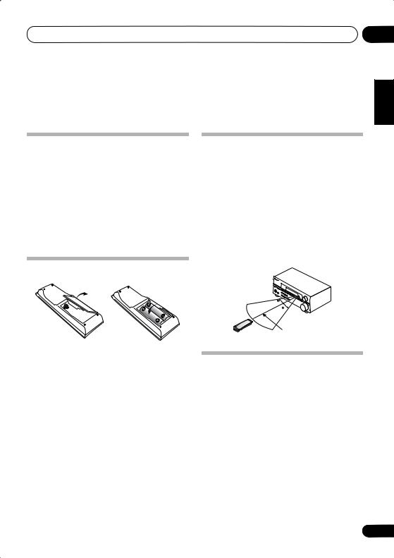
Loading the batteries
Operating range of remote control unit
The remote control may not work properly if:
•There are obstacles between the remote control and the receiver's remote sensor.
•Direct sunlight or fluorescent light is shining onto the remote sensor.
•The receiver is located near a device that is emitting infrared rays.
•The receiver is operated simultaneously with another infrared remote control unit.
01
Italiano Français Deutsch English
 Important
Incorrect use of batteries may result in such hazards as leakage and bursting. Observe the following precautions:
•Never use new and old batteries together.
•Insert the plus and minus sides of the batteries properly according to the marks in the battery case.
•Batteries with the same shape may have different voltages. Do not use different batteries together.
•When disposing of used batteries, please comply with governmental regulations or environmental public instruction’s rules that apply in your country or area.
30
30
23 ft (7m)
Installing the receiver
•When installing this unit, make sure to put it on a level and stable surface.
Don’t install it on the following places:
–on a color TV (the screen may distort)
–near a cassette deck (or close to a device that gives off a magnetic field). This may interfere with the sound.
–in direct sunlight
–in damp or wet areas
–in extremely hot or cold areas
–in places where there is vibration or other movement
–in places that are very dusty
–in places that have hot fumes or oils (such as a kitchen)
Español Nederlands
5
En

02 5 minute guide
Chapter 2:
5 minute guide
Introduction to home theater
You are probably used to using stereo equipment to listen to music, but may not be used to home theater systems that give you many more options (such as surround sound) when listening to soundtracks.
Home theater refers to the use of multiple audio tracks to create a surround sound effect, making you feel like you're in the middle of the action or concert. The surround sound you get from a home theater system depends not only on the speakers you have set up in your room, but also on the source and the sound settings of the receiver.
DVD-Video has become the basic source material for home theater due to its size, quality, and ease of use. Depending on the DVD, you can have up to seven different audio tracks coming from one disc, all of them being sent to different speakers in your system. This is what creates a surround sound effect and gives you the feeling of ‘being there’.
This receiver will automatically decode Dolby Digital, DTS, or Dolby Surround DVD-Video discs, according to your speaker setup. In most cases, you won’t have to make changes for realistic surround sound, but other possibilities (like listening to a CD with multichannel surround sound) are explained in Listening to your system on page 29.
6
En
5 minute guide
Listening to Surround Sound
This receiver was designed with the easiest possible setup in mind, so with the following quick setup guide, you should have your system hooked up for surround sound in no time at all. In most cases, you can simply leave the receiver in the default settings.
Be sure to complete all connections before connecting this unit to the AC power source.
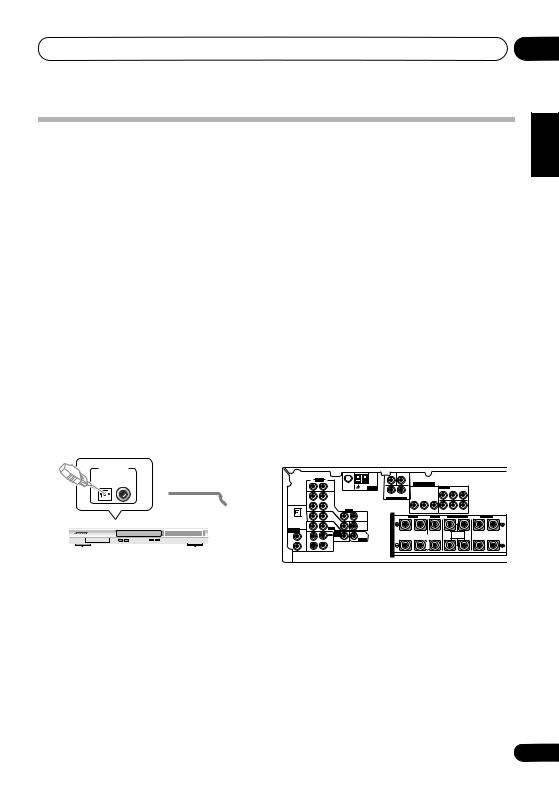
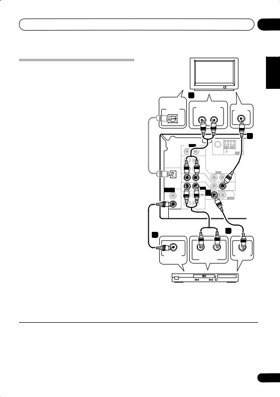
1 Hook up your DVD player.
For surround sound, you’ll want to hook up using a digital connection from the DVD player to the receiver. You can do this with either a coaxial, or an optical connection (you don’t need to connect both). If you hook up using an optical cable, you will need to assign the optical input to DVD (for the VSX-415 see Digital input settings on page 40 and for the VSX-515 see The Input Assign menu on page 44).
Use a video cord to connect the video output on your DVD player to the receiver using the jacks shown below.
2 Hook up your TV.
Use a video cord to connect your receiver to the TV using the jacks as shown below.
Optical cable
VIDEO IN
Video cord
TV
02
Italiano Français Deutsch English
|
|
|
|
|
|
|
|
|
|
|
|
|
|
|
|
|
|
This receiver* |
||||
DIGITAL OUT |
|
|
Coaxial |
|
|
|
|
|
|
|
|
|
|
TER |
WOOFER |
|
|
|
|
|
|
|
|
|
|
|
|
|
|
|
|
|
|
|
|
|
CEN- |
SUB |
|
|
|
|
|
|
|
|
|
|
cable |
OPT |
|
|
R |
AUDIO |
L |
|
|
|
|
|
|
|
|
|
|
|
|
|
|
|
|
1 |
|
|
|
|
|
|
|
|
|
|
|
|
|
|
|
||||
|
|
|
|
|
|
|
|
75 |
Ω |
LOOP |
ANTENNA |
|
|
|
|
ASSIGNABLE |
( DVD / LD) IN ¥ |
|
||||
|
|
|
|
|
|
|
|
|
|
FM UNBAL |
AM |
|
|
|
COMPONENT VIDEO |
|
|
|
|
|||
|
|
|
(TV/SAT) |
|
|
IN |
|
CD |
|
|
|
|
R |
L |
|
|
|
Y |
PB |
PR |
|
|
|
|
|
|
|
|
|
|
|
|
|
|
|
|
SURROUND |
|
|
|
|
|
|
|
|
|
|
|
|
|
|
|
OUT |
|
DVR/ |
|
|
|
|
DVD 5.1CH INPUT |
Y |
PB |
PR |
|
|
|
|
|
|
|
|
|
|
|
|
|
|
|
|
|
|
|
|
|
|
|
|||||
|
|
|
|
|
|
|
|
|
VCR |
|
|
|
|
|
|
|
|
|
|
|
|
|
|
|
|
ASSIGNABLE |
COAX |
|
OPT |
IN |
|
|
VIDEO |
|
|
|
|
|
MONITOR OUT |
|
(T V / SAT) IN ø |
|
|
||
|
|
|
DIGITAL IN |
2 |
|
1 |
|
|
TV / |
IN |
|
OUT |
|
|
R |
VIDEO |
CENTER |
R SURROUND BACK L |
R SURROUND L |
|||
|
|
|
|
(TV/SAT) |
IN |
|
SAT |
|
|
|
S |
FRONT |
L |
|||||||||
|
|
|
|
(CD) |
|
|
|
|
|
|
|
|
|
|
|
|
|
|
||||
|
|
|
|
|
|
|
|
DVD |
IN |
|
|
|
P |
|
|
|
OUT |
|
|
|
|
|
|
|
|
|
|
|
|
|
|
/LD |
|
|
MONITOR |
|
E |
|
|
|
|
|
|
|
|
|
|
|
|
COAX |
ASSIGNABLE |
COAX |
IN |
|
FRONT |
D V D |
|
OUT |
|
|
|
|
|
|
|
|
|
|
|
|
|
|
1 |
DIGITAL IN |
|
|
|
|
|
|
A |
|
|
|
|
|
SINGLE |
|
|||
|
|
|
|
|
2 |
|
|
|
5.1CH |
|
SUB |
|
|
|
|
|
|
|
||||
|
|
|
|
|
(CD) |
|
|
REC |
INPUT |
|
WOOFER |
|
K IN |
|
|
|
|
SEEINSTRUCTION |
|
|||
0 |
7 |
8 |
3 |
(DVD |
|
OUT |
|
CD-R |
IN |
|
PREOUT |
|
|
|
MONITOR |
MANUAL |
|
|
||||
|
|
|
|
/LD) |
|
COAX |
|
/TAPE |
|
|
|
|
E |
|
|
|
|
|
|
|||
|
|
|
|
|
|
|
/MD |
|
|
|
|
|
|
|
OUT |
|
|
|
|
|||
|
|
|
|
|
|
1 |
|
|
|
|
|
|
|
R |
|
|
|
|
|
|
|
|
|
|
|
|
|
|
(DVD |
IN |
|
PLAY |
|
|
|
|
|
|
|
|
|
|
|
|
|
DVD player |
|
|
|
|
|
/LD) |
|
|
|
|
|
|
|
|
|
|
|
|
|
|||
|
|
|
|
|
|
|
|
|
|
|
|
|
S |
|
|
|
WOOFER |
|
|
|
||
|
|
|
|
|
|
|
|
|
|
|
|
|
|
|
|
|
|
SUB |
|
|
|
|
|
|
VIDEO OUT |
|
|
DVD |
|
IN |
|
|
|
|
|
|
|
|
PREOUT |
|
|
|
|||
|
|
|
|
|
|
|
|
|
|
|
|
|
|
|
|
|
|
|||||
|
|
|
|
/ |
LD |
|
|
|
|
|
|
|
|
|
|
|
|
|
|
|
||
FRONT |
|
S |
D V D |
5.1CH |
|
REC |
INPUT |
CD-R |
IN |
/ TAPE |
|
/ MD |
|
Video cord
Español Nederlands
* The illustration shows the VSX-515, but connections for the VSX-415 are the same.
7
En
02 5 minute guide
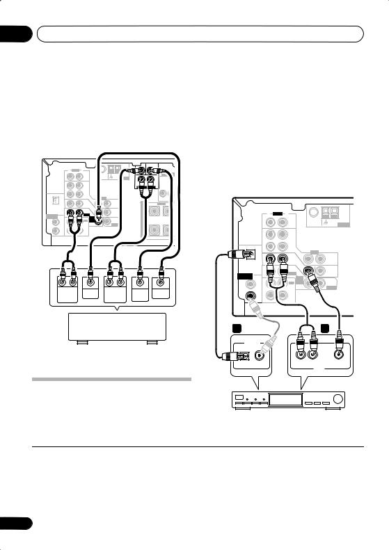
3 Connect your speakers.
A complete setup of speakers is shown here (six speakers for the VSX-415, and eight for the VSX-
515), but home setups may vary. Simply connect the speakers you have as shown below.1 The receiver will work with just two stereo speakers (the front speakers in the diagram) but using at least three speakers is recommended, and a complete setup is best.
Make sure you connect the speaker on the right to the right terminal and the speaker on the left to the left terminal. Also make sure the positive and negative (+/–) terminals on the receiver match those on the speakers. You can use speakers with a nominal impedance between 6–16Ω (please see Switching the speaker impedance on page 51 if you plan to use speakers with an impedance of less than 8Ω).
Front speakers |
Center speaker |
Surround speakers |
||
L |
R |
C |
LS |
RS |
|
|
|
TERCEN- |
SUB WOOFER |
R |
AUDIO L |
|
|
|
|
FM UNBAL |
AM |
|
|
|
75 Ω |
LOOP ANTENNA |
R |
L |
IN |
CD |
|
SURROUND
|
|
OUT |
DVR/ |
|
|
DVD 5.1CH INPUT |
|
|
|
|
|
VCR |
|
|
|
|
|
DIGITAL IN |
|
IN |
|
|
|
|
|
|
|
OPT |
|
VIDEO |
|
FRONT |
CENTER |
||
|
|
|
|
|||||
|
1 |
|
TV / |
IN |
OUT |
SPEAKER |
SPEAKER |
|
|
|
|
||||||
|
(TV / |
IN |
SAT |
|
|
R |
L |
|
|
SAT) |
|
IN |
|
|
|||
ASSIGNABLE |
COAX |
|
DVD |
|
|
|||
|
|
MONITOR |
|
|
|
|||
|
2 |
|
/LD |
|
OUT |
|
|
|
|
(CD) |
IN |
FRONT |
|
|
|
|
|
|
|
D V D |
|
|
|
|
||
|
|
|
|
SUB |
|
|
|
|
|
COAX |
|
|
5.1CH |
|
|
|
|
|
|
REC |
INPUT |
WOOFER |
|
|
|
|
|
1 |
OUT |
CD-R |
IN |
PREOUT |
|
|
|
|
(DVD |
/TAPE |
|
|
|
|
||
|
/LD) |
|
/MD |
|
|
|
|
|
|
|
IN |
PLAY |
|
|
|
|
|
Powered subwoofer
SW
SURROUND |
|
SPEAKERS |
|
R |
L |
|
AC OUTLET |
|
L |
|
R |
|
SURROUND |
|
PREOUT |
VSX-415
INPUT
 Note
Note
1• If you’re not using a subwoofer, change the front speaker setting (see Speaker setting on page 38) to large.
•VSX-515 only – If you are using only one surround back speaker, connect the positive wire to the right channel (+) terminal, and the negative wire to the left channel (–) terminal as shown.
8
En
5 minute guide |
02 |
Front speakers |
Center speaker |
Surround speakers |
Surround back speakers |
|||||||||||
L |
|
R |
|
C |
LS |
|
RS |
|
SBL |
SBR |
||||
|
|
|
|
|
|
|
|
|
|
|
|
|
|
|
|
|
|
|
CEN- |
SUB |
|
|
|
|
|
|
|
TER |
WOOFER |
|
|
|
|
R AUDIO L |
|
|
|
|
|
|
|
|
|
FM UNBAL |
AM |
|
|
COMPONENT VIDEO |
|
|
IN |
CD |
75 Ω |
LOOP ANTENNA |
R |
L |
ASSIGNABLE |
(DVD / LD) IN ¥ |
|
|
|
|
Y |
PB |
PR |
|||
|
|
|
|
|
|
SURROUND |
|
|
|
|
|
|
|
|
|
|
|
OUT |
DVR/ |
|
|
DVD 5.1CH INPUT |
|
Y |
PB |
PR |
|
|
|
|
|
|
|
|
|
|
|
|
|
|
|
|
|||||
|
|
|
VCR |
|
|
|
|
|
|
|
|
|
|
|
|
|
OPT |
IN |
|
|
VIDEO |
|
|
|
MONITOR OUT |
|
(T V / SAT) IN ø |
|
|
|
|
|
1 |
|
TV / |
IN |
OUT |
|
|
FRONT |
|
CENTER |
R SURROUND BACK |
|
|
SURROUND |
|
|
|
|
|
S |
R |
L |
L |
R |
L |
||||||
(TV/SAT) |
IN |
SAT |
|
|
|||||||||||
|
|
|
DVD |
IN |
|
P |
|
|
|
|
|
|
|
|
AC OUTLET |
|
|
|
|
MONITOR |
|
|
|
|
|
|
|
|
|||
|
|
|
/LD |
|
E |
|
|
|
|
|
|
|
|
|
|
ASSIGNABLE |
|
IN |
FRONT |
|
OUT |
|
|
|
|
|
|
|
|
|
|
DIGITAL IN |
COAX |
|
|
D V D |
|
A |
|
|
|
|
SINGLE |
|
|
|
|
|
2 |
|
|
5.1CH |
SUB |
|
|
|
|
|
|
|
|
||
|
(CD) |
|
REC |
INPUT |
WOOFER |
K |
|
|
|
|
SEEINSTRUCTION |
|
|
|
|
|
|
CD-R |
IN |
PREOUT |
|
|
|
|
MANUAL |
|
|
|
|
||
|
COAX |
OUT |
|
|
|
|
|
|
|
|
|
||||
|
|
/TAPE |
|
|
E |
|
|
|
|
|
|
|
|
|
|
|
1 |
|
/MD |
|
|
|
|
|
|
|
|
|
|
|
|
|
(DVD |
IN |
PLAY |
|
|
R |
|
|
|
|
|
|
|
|
|
|
/LD) |
|
|
|
|
|
|
|
|
|
|
|
|||
|
|
|
|
|
|
S |
|
|
|
|
|
|
|
|
|
VSX-515
|
Single |
|
Powered subwoofer |
surround |
|
SW |
back |
|
speaker |
||
|
||
INPUT |
|
4 Plug in the receiver and switch it on, followed by your DVD player, subwoofer and TV.
Make sure you’ve set the video input on your TV to this receiver. Check the manual that came with the TV if you don’t know how to do this.
Also make sure that DVD/LD is showing in the receiver’s display, indicating that the DVD input is selected. If it isn’t, press DVD on the remote control to set the receiver to the DVD input.
5Press QUICK SETUP on the front panel to specify your speaker setup, room size and listening position.
Use the MULTI JOG dial to select and ENTER to confirm your selection. See Using the Quick Setup on page 10 if you’re unsure about the settings.
6Play a DVD, and adjust the volume to your liking.
There are several other sound options you can select. See Listening to your system on page 29 for
more on this.1 See also Choosing your receiver setup on page 37 (VSX-415) or The System Setup menu on page 41 (VSX-515) for more setup options.
 Note
Note
1 Depending on your DVD player or source discs, you may only get digital 2 channel stereo and analog sound. In this case, the listening mode must be set to STANDARD (it should already be set—see Listening in surround sound on page 29 if you need to do this) if you want multichannel surround sound.
Español Nederlands Italiano Français Deutsch English
9
En
02 5 minute guide
Using the Quick Setup
You can use the Quick Setup to get your system up and running with just a few button presses. The receiver automatically makes the necessary settings after you have selected your speaker setup, room size and listening position.
If you want to make more specific settings, refer to Choosing your receiver setup on
page 37 (VSX-415) or The System Setup menu on page 41 (VSX-515).
Use the front panel controls for the steps below.
1If the receiver is off, press STANDBY/ON to turn the power on.
2Press QUICK SETUP.
•VSX-515 model only – SW DET flashes in the display while the receiver checks your setup for a subwoofer. SW YES or SW NO confirms the subwoofer check, then the display prompts you to select your speaker setup.
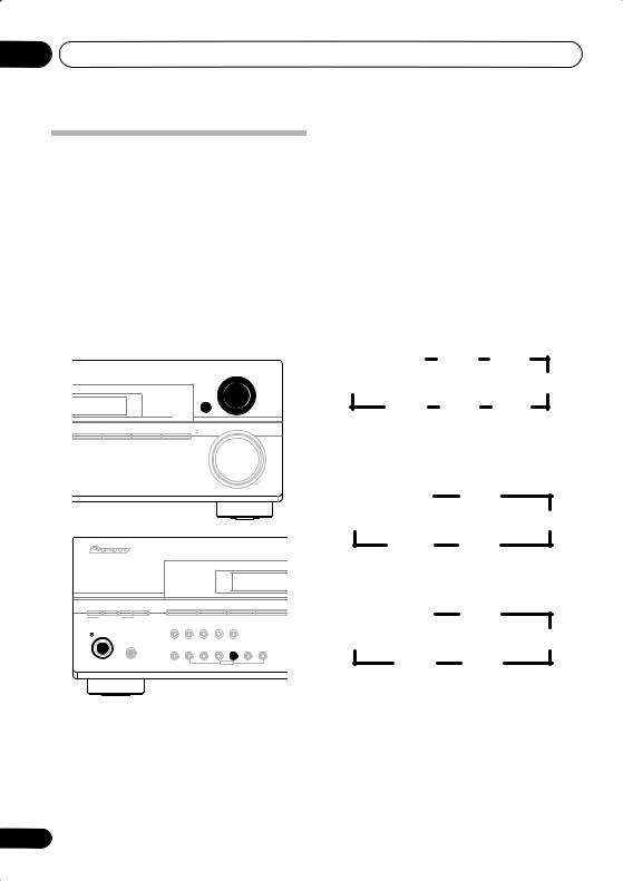
3Use the MULTI JOG dial to choose your speaker setup.
VSX-415 model:
The following choices are available:
AUDIO/VIDEO MULTI-CHANNEL RECEIVER VSX-515
MULTI JOG
ENTER
CD |
CD-R/TAPE/MD |
FM |
AM |
MASTER
VOLUME
DOWN |
UP |
ADVANCED |
ST/DIRECT |
SIGNAL |
DVD/LD |
DVD 5.1 |
TV/SAT |
DVR/VCR |
|||
STANDARD SURR |
/AUTO SURR |
SELECT |
|||||||
LISTENING MODE |
|
|
|
|
|
|
|
|
|
|
|
|
FL DIMMER |
INPUT |
SPEAKER |
EXTENDED |
MUTE |
|
|
|
|
|
ATT |
IMPEDANCE |
MODE |
|
|
||
STANDBY/ON |
|
|
|
|
|
|
|
|
|
|
PHONES |
|
TUNING |
TUNER |
|
QUICK |
SYSTEM |
|
|
|
|
|
CLASS |
/STATION |
EDIT |
TONE |
SETUP |
SETUP |
RETURN |
MULTI JOG
2.0ch |
2.1ch |
3.0ch |
5.1ch |
|
3.1ch |
5.0ch |
4.1ch |
4.0ch |
VSX-515 model:
When a subwoofer was detected in step 2, the following choices are available:
2.1ch 3.1ch
7.1ch |
4.1ch |
6.1ch 5.1ch
If a subwoofer wasn’t detected in step 2, you can cycle between the following choices:
2.0ch 3.0ch
7.0ch |
4.0ch |
6.0ch 5.0ch
* Illustration shows the VSX-515 model
10
En
5 minute guide
•Check the table below to find the speaker setup that corresponds with your system.
* VSX-515 model only
4Press ENTER.
5Use the MULTI JOG dial to choose your room size.
Depending on the distance of your speakers from the listening position, choose between small, medium, or large (S, M or L), M being an average-sized room.
6Press ENTER.
7Use the MULTI JOG dial to choose your listening position.
You can cycle between the following choices:
•FWD – If you are nearer to the front speakers than the surround speakers
•MID – If you are equal distance from the front and surround speakers
•BACK – If you are nearer to the surround speakers than the front speakers
8Press ENTER to confirm your setup.
The display shows the speaker setup, room size and listening position that you have selected.
02
Español Nederlands Italiano Français Deutsch English
11
En
03 Connecting up
Chapter 3:
Connecting up
Making cable connections
Make sure not to bend the cables over the top of this unit (as shown in the illustration). If this happens, the magnetic field produced by the transformers in this unit may cause a humming noise from the speakers.
 Important
•Before making or changing any connections, switch off the power and disconnect the power cord from the AC outlet.
Digital audio cables
Commercially available coaxial digital audio cables or optical cables should be used to
connect digital components to this receiver.1
Coaxial digital audio cable |
Optical cable |
Video cables
Standard RCA video cables
These cables are the most common type of video connection and should be used to connect to the composite video terminals. They have yellow plugs to distinguish them from cables for audio.
Standard RCA video cable
Analog audio cables
Use stereo RCA phono cables to connect analog audio components. These cables are typically red and white, and you should connect the red plugs to R (right) terminals and white plugs to L (left) terminals.
Analog audio cables
Right (red)
Left (white)
Component video cables (VSX-515 only)
Use component video cables to get the best possible color reproduction of your video source. The color signal of the TV is divided into the luminance (Y) signal and the color (PB and PR) signals and then output. In this way, interference between the signals is avoided.
Component video cables
Green (Y)
Blue (PB)
Red (PR)
 Note
Note
1• When connecting optical cables, be careful when inserting the plug not to damage the shutter protecting the optical socket.
•When storing optical cable, coil loosely. The cable may be damaged if bent around sharp corners.
•You can also use a standard RCA video cable for coaxial digital connections.
12
En
Connecting up
Connecting a DVD player and TV
This page shows you how to connect your DVD player and TV to the receiver.
1 Connect a coaxial digital audio output on your DVD player to the DIGITAL COAX 1 (DVD/LD) input on this receiver.
Use a coaxial digital audio cable for the connection.1
2 Connect the composite video output and
the stereo analog audio outputs2 on your DVD player to the DVD/LD inputs on this receiver.
Use a standard RCA video cable3 and a stereo RCA phono cable for the connection.
•If your DVD player has multichannel analog outputs, see Connecting the multichannel analog outputs below for how to connect it.
3Connect the analog audio outputs from your TV to the TV/SAT inputs on this receiver.
This will allow you to play the sound from the TV's built-in tuner. Use a stereo RCA phono cable to do this.
•If your TV has a built-in digital decoder, you can also connect an optical digital audio output from your TV to the DIGITAL OPT 1 (TV/SAT) input on this receiver. Use an optical cable for the connection.
4Connect the MONITOR OUT video jack on this receiver to a video input on your TV.
Use a standard RCA video cable to connect to
the composite video jack.4
DIGITAL |
4 |
|
TV |
|
|
|
|
||
AUDIO OUT |
ANALOG AUDIO OUT |
|
||
OPTICAL |
VIDEO IN |
|||
R |
L |
|||
|
||||
|
|
|||
3
|
|
R |
AUDIO L |
|
|
|
|
|
|
FM UNBAL |
AM |
|
|
IN |
CD |
75 Ω |
LOOP ANTENNA |
|
|
OUT |
DVR/ |
|
|
|
|
|
VCR |
|
|
|
OPT |
IN |
|
VIDEO |
|
|
1 |
|
TV / |
IN |
OUT |
|
|
|
|
||
(TV/SAT) |
|
SAT |
|
||
IN |
|
|
|||
|
|
|
DVD |
IN |
|
|
|
|
|
MONITOR |
|
|
|
|
/LD |
|
|
|
|
|
|
OUT |
|
ASSIGNABLE |
|
IN |
FRONT |
|
|
COAX |
D V D |
|
|||
DIGITAL IN |
|
|
|
||
|
2 |
|
REC |
5.1CH |
SUB |
|
(CD) |
|
INPUT |
WOOFER |
|
|
|
CD-R |
IN |
PREOUT |
|
|
COAX |
OUT |
|||
|
|
/TAPE |
|
|
|
|
1 |
|
/MD |
|
|
|
|
|
|
|
|
|
(DVD |
IN |
PLAY |
|
|
|
/LD) |
|
|
||
This receiver*
2
1
COAXIAL |
R AUDIO L |
VIDEO OUT |
DIGITAL OUT |
ANALOG OUT |
|
DVD player
* The illustration shows the VSX-515, but connections for the VSX-415 are the same.
03
Español Nederlands Italiano Français Deutsch English
 Note
Note
1If your DVD player only has an optical digital output, you can connect it to the optical input on this receiver using an optical cable. When you set up the receiver you'll need to tell the receiver which input you connected the player to (for the VSX-415 see
Digital input settings on page 40 and for the VSX-515 see The Input Assign menu on page 44).
2This connection will allow you to make analog recordings from your DVD player.
3VSX-515 model only – If your player also has a component video output, you can connect this too. See Using the component video jacks on page 16 for more on this.
4VSX-515 model only – See Using the component video jacks on page 16 if you want to use the component video outputs to connect this receiver to your TV.
13
En
03 Connecting up
Connecting the multichannel analog outputs
For DVD Audio and SACD playback, your DVD player may have 5.1 channel analog outputs.In this case, you can connect them to the multi-
channel inputs of the receiver as shown below.1
This receiver*
|
|
|
|
|
|
CEN- |
SUB |
|
|
|
|
|
|
|
|
|
TER |
WOOFER |
|
|
|
|
|
R |
AUDIO L |
|
|
|
|
|
|
|
|
|
|
|
FM UNBAL |
AM |
|
|
COMPONENT VIDEO |
||
|
|
IN |
CD |
75 Ω |
LOOP ANTENNA |
R |
|
L |
|
|
|
|
|
|
|
|
SURROUND |
|
|
|
|
|
|
OUT |
DVR/ |
|
|
DVD 5.1CH INPUT |
Y |
PB |
PR |
|
|
|
|
VCR |
|
|
|
|
|
|
|
|
OPT |
IN |
|
VIDEO |
|
|
|
|
MONITOR OUT |
|
|
1 |
|
TV / |
IN |
OUT |
|
|
R FRONT |
|
CENT |
|
|
|
|
S |
|
L |
||||
(TV/SAT) |
IN |
SAT |
|
|
|
|||||
|
|
|
DVD |
IN |
|
P |
|
|
|
|
|
|
|
|
MONITOR |
|
|
|
|
||
|
|
|
/LD |
|
E |
|
|
|
|
|
ASSIGNABLE |
|
IN |
FRONT |
|
OUT |
|
|
|
|
|
DIGITAL IN |
COAX |
|
|
D V D |
|
A |
|
|
|
|
|
2 |
|
|
5.1CH |
SUB |
|
|
|
|
|
|
(CD) |
|
REC |
INPUT |
WOOFER |
K |
|
|
|
|
|
|
OUT |
CD-R |
IN |
PREOUT |
|
|
|
|
|
|
COAX |
/TAPE |
|
E |
|
|
|
|
||
|
1 |
|
/MD |
|
|
|
|
|
|
|
|
(DVD |
IN |
PLAY |
|
|
R |
|
|
|
|
|
/LD) |
|
|
S |
|
|
|
|
||
|
|
|
|
|
|
|
|
|
|
|
R |
L |
CENTER |
R |
L |
SUB |
VIDEO |
FRONT |
OUTPUT |
SURROUND |
WOOFER |
OUTPUT |
||
OUTPUT |
|
OUTPUT |
OUTPUT |
|
||
DVD/multi-channel decoder with multi-channel analog output jacks
* The illustration shows the VSX-515, but connections for the VSX-415 are the same.
Connecting a satellite receiver or other digital set-top box
Satellite and cable receivers, and terrestrial digital TV tuners are all examples of so-called `set-top boxes'.
1 Connect a set of audio/video outputs on the set-top box component to the TV/SAT
AUDIO and VIDEO inputs on this receiver.2
Use a stereo RCA phono cable for the audio connection and a standard RCA video cable for
the video connection.3
2 Connect an optical digital audio output from your set-top box component to the DIGITAL OPT 1 (TV/SAT) input on this receiver.
Use an optical cable for the connection.4
This receiver*
|
|
R |
AUDIO L |
|
|
|
|
|
|
FM UNBAL |
AM |
|
|
IN |
CD |
75 Ω |
LOOP ANTENNA |
|
|
OUT |
DVR/ |
|
|
|
|
|
VCR |
|
|
|
OPT |
IN |
|
VIDEO |
|
|
1 |
|
TV / |
IN |
OUT |
|
|
|
|
||
(TV/SAT) |
|
SAT |
|
||
IN |
|
|
|||
|
|
|
|
|
|
|
|
|
DVD |
IN |
|
|
|
|
|
MONITOR |
|
|
|
|
/LD |
|
|
|
|
|
|
OUT |
|
ASSIGNABLE |
|
IN |
FRONT |
|
|
COAX |
D V D |
|
|||
DIGITAL IN |
|
|
|
||
|
2 |
|
REC |
5.1CH |
SUB |
|
(CD) |
|
INPUT |
WOOFER |
|
|
|
CD-R |
IN |
PREOUT |
|
|
COAX |
OUT |
|||
|
|
/TAPE |
|
|
|
|
1 |
|
/MD |
|
|
|
|
|
|
|
|
|
(DVD |
IN |
PLAY |
|
|
|
/LD) |
|
|
||
2 |
|
|
1 |
DIGITAL OUT |
|
|
|
OPTICAL |
COAXIAL |
R AUDIO L |
VIDEO |
|
|
|
AV OUT |
STB
* The illustration shows the VSX-515, but connections for the VSX-415 are the same.
 Note
Note
1The multichannel input can only be used when DVD 5.1 ch is selected (see page 36).
2If you've already connected your TV to the TV/SAT inputs, simply choose another input. However, you'll need to tell the receiver which input you connected the set-top box to (for the VSX-415 see Digital input settings on page 40 and for the VSX-515 see The Input Assign menu on page 44).
3VSX-515 model only – See Using the component video jacks on page 16 if your set-top box also has a component video output.
4If your set-top box doesn’t have a digital audio output, omit this step. If it only has a coaxial digital output, you can connect it to one of the coaxial inputs on this receiver, but you'll need to tell the receiver which input you connected the set-top box to (for the VSX-415 see Digital input settings on page 40 and for the VSX-515 see The Input Assign menu on page 44).
14
En
Connecting up
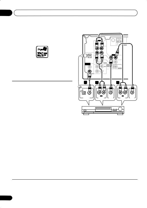
Connecting other audio components
The number and kind of connections depends
on the kind of component you’re connecting.1 Follow the steps below to connect a CD-R, MD, DAT, tape recorder or other audio component.
1If your component has a digital output, connect this to a digital input on the receiver as shown.
The example shows a coaxial connection to the CD digital input jack using a coaxial digital audio cable.
2If necessary, connect the analog audio outputs of the component to a set of spare audio inputs on this receiver.
You’ll need to make this connection for components without a digital output, or if you want to record from a digital component. Use a stereo RCA phono cable as shown.
3If you're connecting a recorder, connect the analog audio outputs (REC) to the analog audio inputs on the recorder.
The example shows an analog connection to the CD-R/TAPE/MD analog output jack using a stereo RCA phono cable.
03
This receiver* |
|
|
|
|
English |
||
|
|
R AUDIO |
L |
|
|
|
|
|
|
|
|
FM UNBAL |
AM |
|
|
|
|
IN |
CD |
75 Ω |
LOOP |
ANTENNA |
|
|
|
|
|
|
|
||
|
|
OUT |
DVR/ |
|
|
|
Deutsch |
|
|
|
VCR |
|
|
|
|
|
|
|
|
|
|
|
|
|
OPT |
IN |
|
VIDEO |
|
|
|
|
1 |
|
TV / |
IN |
OUT |
|
|
|
|
|
|
|
|
||
(TV/SAT) |
|
SAT |
|
|
|
||
IN |
|
|
|
|
|||
|
|
|
|
|
|
|
|
|
|
|
DVD |
IN |
|
|
|
|
|
|
|
MONITOR |
|
|
|
|
|
|
/LD |
|
|
|
|
|
|
|
|
OUT |
|
|
|
ASSIGNABLE |
|
IN |
FRONT |
|
|
|
|
COAX |
D V D |
|
|
|
|||
DIGITAL IN |
|
|
|
|
|
||
|
2 |
|
REC |
5.1CH |
SUB |
|
|
|
(CD) |
|
INPUT |
WOOFER |
|
Français |
|
|
|
OUT |
CD-R |
IN |
PREOUT |
|
|
|
COAX |
/TAPE |
|
|
|
||
|
|
/MD |
|
|
|
|
|
|
1 |
|
|
|
|
|
|
|
|
|
|
|
|
|
|
|
(DVD |
IN |
PLAY |
|
|
|
|
|
/LD) |
|
|
|
|
||
1 |
|
2 |
|
|
3 |
|
Italiano |
|
|
|
|
|
|||
OPTICAL |
COAXIAL |
R OUT L |
R |
IN |
L |
||
|
|
|
PLAY |
|
REC |
Nederlands |
|
DIGITAL OUT |
|
AUDIO OUT |
AUDIO IN |
|
|||
connections for the VSX-415 are the same. |
Español |
||||||
CD-R, MD, DAT, Tape recorder, etc. |
|
||||||
* The illustration shows the VSX-515, but
About the WMA9 Pro decoder
VSX-515 model only
This unit has an on-board Windows Media® Audio 9 Professional (WMA9 Pro) decoder, so it is possible to playback WMA9 Pro-encoded audio using a coaxial or optical digital connection when connected to a WMA9 Pro-
 Note
Note
1 Note that you must connect digital components to analog audio jacks if you want to record to/from digital components (like an MD) to/from analog components.
15
En
03 Connecting up
compatible player. However, the connected PC, DVD player, set-top box, etc. must be able to output WMA9 Pro format audio signals through a coaxial or optical digital output.
Microsoft, Windows Media®, and the Windows logo are trademarks, or registered trademarks of Microsoft Corporation in the United States and/ or other countries.
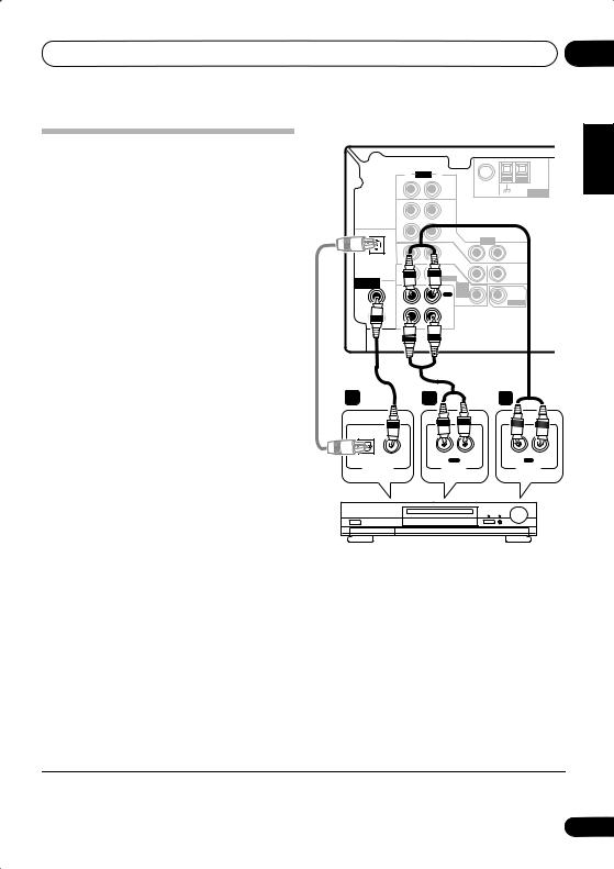
Connecting other video components
This receiver has audio/video inputs and outputs suitable for connecting analog or digital video recorders, including VCRs, DVDrecorders and HDD recorders.
1Connect a set of audio/video outputs on the recorder to the DVR/VCR AUDIO and VIDEO inputs on this receiver.
Use a stereo RCA phono cable for the audio connection and a standard RCA video or S- video cable for the video connection.
2Connect a set of audio/video inputs on the recorder to the DVR/VCR AUDIO and VIDEO outputs on this receiver.
Use a stereo RCA phono cable for the audio connection and a standard RCA video or S- video cable for the video connection.
3If your video component has a digital audio output, connect it to a digital input on this receiver.
The example shows a recorder connected to
the DIGITAL COAX 1 (DVD/LD) input.1
This receiver*
|
|
|
R |
AUDIO |
L |
|
|
|
|
|
|
|
|
|
FM UNBAL |
AM |
|
|
|
|
IN |
|
CD |
75 Ω |
LOOP ANTENNA |
|
|
|
|
OUT |
|
DVR/ |
|
|
|
|
|
|
|
|
VCR |
|
|
|
|
|
OPT |
IN |
|
|
VIDEO |
|
|
|
|
1 |
|
|
TV / |
IN |
OUT |
|
|
|
|
|
|
|
|
||
|
(TV/SAT) |
|
|
SAT |
|
|
||
|
IN |
|
|
|
|
|||
|
|
|
|
|
DVD |
IN |
|
|
|
|
|
|
|
|
MONITOR |
|
|
|
|
|
|
|
/LD |
|
|
|
|
|
|
|
|
|
OUT |
|
|
ASSIGNABLE |
|
IN |
|
FRONT |
|
|
||
COAX |
|
D V D |
|
|
||||
DIGITAL IN |
|
|
|
|
|
|||
|
|
2 |
|
|
REC |
5.1CH |
SUB |
|
|
|
(CD) |
|
|
INPUT |
WOOFER |
|
|
|
|
|
|
CD-R |
IN |
PREOUT |
|
|
|
|
COAX |
OUT |
|
|
|||
|
|
|
|
/TAPE |
|
|
|
|
|
|
1 |
|
|
/MD |
|
|
|
|
|
|
|
|
|
|
|
|
|
|
(DVD |
IN |
|
PLAY |
|
|
|
|
|
/LD) |
|
|
|
|
||
3 |
|
|
1 |
|
|
|
2 |
|
OPTICAL |
COAXIAL |
|
|
R OUT |
L |
|
R IN L |
|
|
|
|
|
PLAY |
|
|
REC |
|
DIGITAL OUT |
|
|
AUDIO OUT |
VIDEO OUT |
AUDIO IN |
VIDEO IN |
||
VCR, DVR, LD player, etc.
* The illustration shows the VSX-515, but connections for the VSX-415 are the same.
Using the component video jacks
VSX-515 model only
Component video should deliver superior picture quality when compared to composite video. A further advantage (if your source and TV are both compatible) is progressive-scan video, which delivers a very stable, flicker-free picture. See the manuals that came with your TV and source component to check whether they are compatible with progressive-scan video.
 Note
Note
1 If your video component doesn’t have a digital audio output, omit this step. If it only has an optical digital output, you can connect it to the optical input on this receiver using an optical cable. When you set up the receiver you'll need to tell the receiver which input you connected the component to (for the VSX-415 see Digital input settings on page 40 and for the VSX-515 see The Input Assign menu on page 44).
16
En

Connecting up
 Important
•If you connect any source component to the receiver using a component video input, you must also have your TV connected to this receiver's COMPONENT VIDEO MONITOR OUT jacks.
1Connect the component video outputs of your source to a set of component video inputs on this receiver.
Use a three-way component video cable for the connection.
2If necessary, assign the component video inputs to the input source you've connected.
This only needs to be done if you didn’t connect according to the following defaults:
•COMP 1 – DVD
•COMP 2 – TV
See Assigning the component video inputs on page 44).
3 Connect the COMPONENT VIDEO MONITOR OUT jacks on this receiver to the component video inputs on your TV or monitor.
Use a three-way component video cable.
03
Español Nederlands Italiano Français Deutsch English
17
En
03 Connecting up
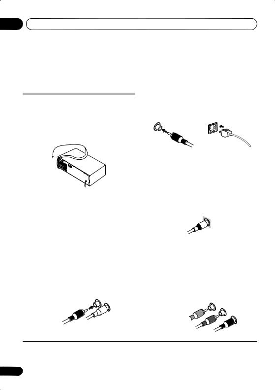
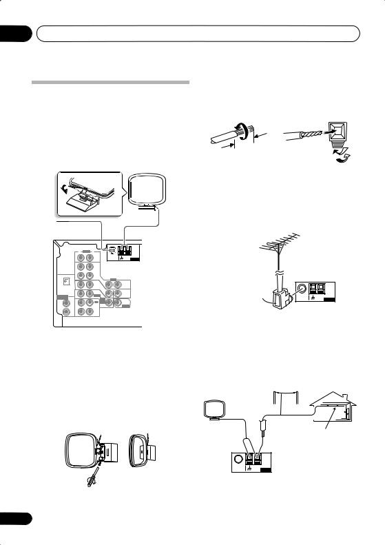
Connecting antennas
Connect the AM loop antenna and the FM wire antenna as shown below. To improve reception and sound quality, connect external antennas (see Using external antennas below). Always make sure that the receiver is switched off and unplugged from the wall outlet before making or changing any connections.
FM wire antenna
|
|
|
|
|
|
CEN- |
SUB |
|
|
|
|
|
|
TER |
WOOFER |
|
|
R |
AUDIO L |
|
|
|
|
|
|
|
|
FM UNBAL |
AM |
|
|
|
|
IN |
CD |
75 Ω |
LOOP ANTENNA |
R |
L |
|
|
|
|
|
|
SURROUND |
|
|
|
OUT |
DVR/ |
|
|
DVD 5.1CH INPUT |
|
|
|
|
|
|
|
||
|
|
|
VCR |
|
|
|
|
|
OPT |
IN |
|
VIDEO |
|
|
|
|
1 |
|
TV / |
IN |
OUT |
|
R F |
|
|
|
|
S |
|||
(TV/SAT) |
IN |
SAT |
|
|
|||
|
|
|
DVD |
IN |
|
P |
|
|
|
|
|
MONITOR |
|
||
|
|
|
/LD |
|
E |
|
|
ASSIGNABLE |
|
IN |
FRONT |
|
OUT |
|
|
COAX |
D V D |
|
|
||||
DIGITAL IN |
|
|
|
A |
|
||
|
2 |
|
|
5.1CH |
SUB |
|
|
|
(CD) |
|
REC |
INPUT |
WOOFER |
K |
|
|
|
OUT |
CD-R |
IN |
PREOUT |
|
|
|
COAX |
/TAPE |
|
E |
|
||
|
1 |
|
/MD |
|
|
|
|
|
|
|
|
|
R |
|
|
|
(DVD |
IN |
PLAY |
|
|
|
|
|
/LD) |
|
|
|
|
||
S
FM wire antenna
Connect the FM wire antenna and fully extend vertically along a window frame or another suitable place that gives good reception.
AM loop antenna
Assemble the antenna and connect to the receiver. Attach (if necessary) and face in the direction that gives the best reception.
Antenna snap connectors
Twist the exposed wire strands together and insert into the hole, then snap the connector shut.
3/8 in. (10mm)
Using external antennas
To improve FM reception
Use an F connector to connect an external FM antenna.
F connector |
FM UNBAL |
AM |
|
75 Ω |
LOOP ANTENNA |
To improve AM reception
Connect a 15–18 foot length of vinyl-coated wire to the AM antenna terminal without disconnecting the supplied AM loop antenna.
For the best possible reception, suspend horizontally outdoors.
Outdoor antenna
15–18 ft. (5–6m)
Indoor antenna (vinyl-coated wire)
FM UNBAL |
AM |
75 Ω |
LOOP ANTENNA |
18
En
Connecting up
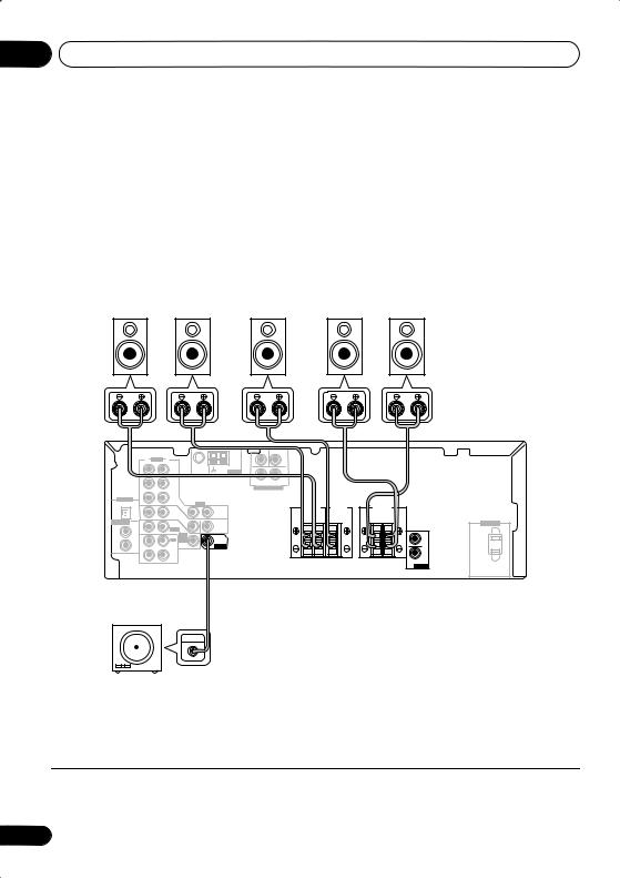
Connecting the speakers (VSX-415)
A complete setup of six speakers (including the subwoofer) is shown below, but everyone’s home setup will vary. Simply connect the speakers you have in the manner shown below. The receiver will work with just two stereo speakers (the front speakers in the diagram) but using at least three speakers is recommended, and a complete setup is best. If you’re not using a subwoofer, change the front speaker setting (see Speaker setting on page 38) to large.
Make sure you connect the speaker on the right to the right terminal and the speaker on the left to the left terminal. Also make sure the positive and negative (+/–) terminals on the receiver match those on the speakers. You can use speakers with a nominal impedance between 6–16Ω (please see Switching the speaker impedance on page 51 if you plan to use speakers with an impedance of less than 8Ω).
Be sure to complete all connections before connecting this unit to the AC power source.
Front speakers |
Center speaker |
Surround speakers |
||
L |
R |
C |
LS |
RS |
03
Italiano Français Deutsch English
|
|
|
TERCEN- |
SUB WOOFER |
R |
AUDIO L |
|
|
|
|
FM UNBAL |
AM |
|
|
|
75 Ω |
LOOP ANTENNA |
R |
L |
IN |
CD |
|
SURROUND
|
|
OUT |
DVR/ |
|
|
DVD 5.1CH INPUT |
|
|
|
|
|
VCR |
|
|
|
|
|
DIGITAL IN |
|
IN |
|
|
|
|
|
|
|
OPT |
|
VIDEO |
|
FRONT |
CENTER |
||
|
|
|
|
|||||
|
1 |
|
TV / |
IN |
OUT |
SPEAKER |
SPEAKER |
|
|
|
|
||||||
|
(TV / |
IN |
SAT |
|
|
R |
L |
|
|
SAT) |
|
IN |
|
|
|||
ASSIGNABLE |
COAX |
|
DVD |
|
|
|||
|
|
MONITOR |
|
|
|
|||
|
2 |
|
/LD |
|
|
|
|
|
|
(CD) |
IN |
FRONT |
|
OUT |
|
|
|
|
|
D V D |
|
|
|
|
||
|
|
|
|
SUB |
|
|
|
|
|
COAX |
|
|
5.1CH |
|
|
|
|
|
|
REC |
INPUT |
WOOFER |
|
|
|
|
|
1 |
|
|
|
|
|||
|
OUT |
CD-R |
IN |
PREOUT |
|
|
|
|
|
(DVD |
/TAPE |
|
|
|
|
||
|
/LD) |
|
/MD |
|
|
|
|
|
|
|
IN |
PLAY |
|
|
|
|
|
SURROUND |
|
SPEAKERS |
|
R |
L |
L
R
SURROUND
PREOUT
Powered subwoofer |
1 |
2 |
or |
SW |
INPUT |
|
ª |
10mm |
|
|
|
· |
|
|
|
VSX-415
AC OUTLET
ª ·
The SURROUND
PREOUT terminal is intended for use with a wireless speaker system. See your wireless speaker manual for more details on connecting up.
3 
ª ·
Español Nederlands
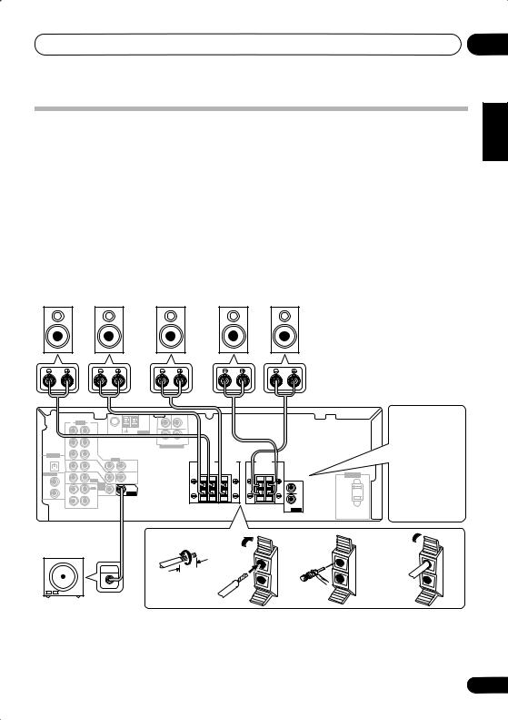
1Twist exposed wire strands together.
2Unclip speaker terminal and insert wire.
•The speaker terminals also accept single banana plugs.
3 Snap shut the speaker terminal to secure.
19
En

03 Connecting up
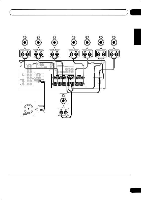
Connecting the speakers (VSX-515)
A complete setup of eight speakers (including the subwoofer) is shown below, but everyone’s home setup will vary. Simply connect the speakers you have in the manner shown below. The receiver will work with just two stereo speakers (the front speakers in the diagram) but using at least three speakers is recommended, and a complete setup is best for surround sound. If you’re not using a subwoofer, change the front speaker setting (see Speaker setting on page 42) to large.
Make sure you connect the speaker on the right to the right terminal and the speaker on the left to the left terminal. Also make sure the positive and negative (+/–) terminals on the receiver match
those on the speakers.1 You can use speakers with a nominal impedance between 6–16Ω (please see Switching the speaker impedance on page 51 if you plan to use speakers with an impedance of less than 8Ω).
Be sure to complete all connections before connecting this unit to the AC power source.
Front speakers |
Center speaker |
Surround speakers |
Surround back speakers |
|||||||||||
L |
|
R |
|
C |
LS |
|
RS |
|
SBL |
SBR |
||||
|
|
|
|
|
|
|
|
|
|
|
|
|
|
|
|
|
|
CEN- |
SUB |
|
|
|
|
|
|
TER |
WOOFER |
|
|
|
R |
AUDIO L |
|
|
|
|
|
|
|
FM UNBAL |
AM |
|
|
COMPONENT VIDEO |
|
|
|
75 Ω |
LOOP ANTENNA |
R |
L |
ASSIGNABLE |
(DVD / LD) IN ¥ |
|
IN |
CD |
|
Y |
PB |
PR |
||
|
|
|
|
|
|
SURROUND |
|
|
|
|
|
|
|
|
|
|
|
OUT |
DVR/ |
|
|
DVD 5.1CH INPUT |
|
Y |
PB |
PR |
|
|
|
|
|
|
|
|
|
|
|
|
|
|
|
|
|||||
|
|
|
VCR |
|
|
|
|
|
|
|
|
|
|
|
|
|
OPT |
IN |
|
|
VIDEO |
|
|
|
MONITOR OUT |
|
(T V / SAT) IN ø |
|
|
|
|
|
1 |
|
TV / |
IN |
|
|
|
FRONT |
|
CENTER |
R SURROUND BACK |
|
|
SURROUND |
|
|
|
|
|
OUT |
S |
R |
L |
L |
R |
L |
|||||
(TV/SAT) |
IN |
SAT |
|
|
|||||||||||
|
|
|
DVD |
IN |
|
P |
|
|
|
|
|
|
|
|
AC OUTLET |
|
|
|
/LD |
|
MONITOR |
E |
|
|
|
|
|
|
|
|
|
ASSIGNABLE |
|
IN |
FRONT |
|
OUT |
|
|
|
|
|
|
|
|
|
|
COAX |
D V D |
|
|
|
|
|
|
|
|
|
|
||||
DIGITAL IN |
|
|
|
A |
|
|
|
|
SINGLE |
|
|
|
|
||
|
2 |
|
|
5.1CH |
SUB |
|
|
|
|
|
|
|
|
||
|
(CD) |
|
REC |
INPUT |
WOOFER |
K |
|
|
|
|
SEEINSTRUCTION |
|
|
|
|
|
|
CD-R |
IN |
PREOUT |
|
|
|
|
MANUAL |
|
|
|
|
||
|
COAX |
OUT |
|
|
|
|
|
|
|
|
|
||||
|
|
/TAPE |
|
|
E |
|
|
|
|
|
|
|
|
|
|
|
1 |
|
/MD |
|
|
|
|
|
|
|
|
|
|
|
|
|
|
|
|
|
R |
|
|
|
|
|
|
|
|
|
|
|
(DVD |
IN |
PLAY |
|
|
|
|
|
|
|
|
|
|
|
|
|
/LD) |
|
|
|
|
|
|
|
|
|
|
|
|||
|
|
|
|
|
|
S |
|
|
|
|
|
|
|
|
|
VSX-515 |
Single |
|
|
|
|
Powered subwoofer |
surround |
|
|
|
|
back |
1 |
2 |
3 |
||
SW |
speaker |
||||
|
|
|
|||
INPUT |
|
|
10mm |
or |
|
|
|
|
1Twist exposed wire strands together.
2Loosen terminal and insert exposed wire.
•The speaker terminals also accept single banana plugs.
3 Tighten terminal.
 Note
Note
1 If you are using only one surround back speaker, connect the positive wire to the right channel (+) terminal, and the negative wire to the left channel (–) terminal (see illustration).
20
En
Connecting up |
03 |
Speaker terminals
Make sure that all the bare speaker wire is twisted together and inserted fully into the speaker terminal. If any of the bare speaker wire is touching the back panel when you switch the unit on, the power may cut off as a safety measure. Use good quality speaker wire to connect the speakers to the receiver.
 Caution
•These speaker terminals are hazardous when live. To prevent the risk of electric shock when connecting or disconnecting the speaker cables, disconnect the power cord.
Hints on speaker placement
Speakers are usually designed with a particular placement in mind. Some are designed to be floorstanding, while others should be placed on stands to sound their best. Some should be placed near a wall; others should be placed away from walls. We have provided a few tips on getting the best sound from your speakers (following), but you should also follow the guidelines on placement that the speaker manufacturer provided with your particular speakers to get the most out of them.
•Place the front left and right speakers at equal distances from the TV.
•When placing speakers near the TV, we recommend using magnetically shielded speakers to prevent possible interference, such as discoloration of the picture when the TV is switched on. If you do not have magnetically shielded speakers and notice discoloration of the TV picture, move the speakers farther away from the TV.
•Place the center speaker above or below the TV so that the sound of the center channel is localized at the TV screen.
•If possible, place the surround speakers slightly above ear level.
•Try not to place the surround speakers further away from the listening position than the front and center speakers. Doing so can weaken the surround sound effect.
•To achieve the best possible surround sound, install your speakers as shown below. Be sure all speakers are installed securely to prevent accidents and improve sound quality.
 Caution
•If you choose to install the center speaker on top of the TV, be sure to secure it with putty, or by other suitable means, to reduce the risk of damage or injury resulting from the speaker falling from the TV in the event of external shocks such as earthquakes.
•Make sure no exposed speaker wire is touching the rear panel, this may cause the receiver to turn off automatically.
Speaker placement diagrams
The following illustrations show 6.1 and 7.1 channel speaker setups.1
3-D view of 6.1 channel speaker setup
 Note
Note
1 VSX-415 model only – Follow the speaker placement diagrams, disregarding the surround back speakers.
Español Nederlands Italiano Français Deutsch English
21
En

03 Connecting up
3-D view of 7.1 channel speaker setup
Overhead view of speaker setup
Front |
|
Front |
left |
Center |
right |
|
|
Subwoofer |
Surround |
|
Surround |
left |
|
right |
Listening position |
||
Surround back left |
|
Surround back right |
Single surround back speaker
Extra Power mode speaker setup
VSX-415 only – see Using the Advanced surround effects on page 30 to switch on the Extra Power mode (EX POWER).
Front left |
Center |
Front right |
|
Subwoofer |
|
Surround |
|
Surround |
left |
|
right |
Listening position |
||
|
|
. |
22
AC outlet
Power supplied through this outlet is turned on and off by the receiver's power switch. Total electrical power consumption of connected equipment should not exceed 100 W (0.8 A).
•This unit should be disconnected by removing the power plug from the wall socket when not in regular use (ex. when on vacation).
AC OUTLET
 Caution
•Do not connect a TV set, monitor, heater, or similar appliance to this unit's AC outlet.
•Do not connect appliances with high power consumption to the AC outlet in order to avoid overheating and fire risk. This can also cause the receiver to malfunction.
•Since a subwoofer or power amplifier can exceed the 100W maximum when playing sources at a high volume, this type of equipment should not be connected to the AC outlet.
En
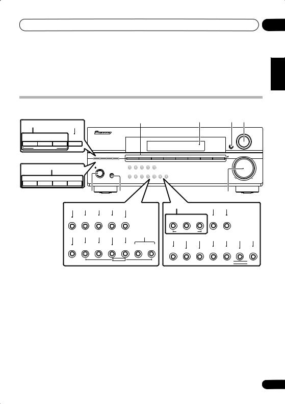
Controls and displays
Chapter 4:
Controls and displays
Front panel
1 |
2 |
3 |
4 |
8 |
9 |
|
|
|
|
AUDIO/VIDEO MULTI-CHANNEL RECEIVER |
|
ADVANCED |
ST/DIRECT |
SIGNAL |
MULTI JOG |
STANDARD |
|
|||
SURR |
/AUTO SURR |
SELECT |
|
|
|
|
|
|
ENTER |
LISTENING MODE |
|
|
||
VSX-515 model |
DVD/LD DVD 5.1 TV/SAT DVR/VCR |
CD CD-R/TAPE/MD FM |
MASTER |
|
AM |
VOLUME
16 |
STANDBY/ON |
|
|
|
|
|
|
PHONES |
|
– |
STATION |
+ |
– |
TUNING |
+ |
DOWN |
UP |
VSX-415 model |
|
5 |
|
6 |
|
|
7 |
|
|
|
|
|
|||
10 |
11 |
12 |
13 |
14 |
8 |
9 |
21 |
FL DIMMER |
INPUT |
SPEAKER |
EXTENDED |
MUTE |
ATT |
IMPEDANCE |
MODE |
15 |
16 |
17 |
18 |
19 |
20 |
|
TUNING |
TUNER |
|
QUICK |
SYSTEM |
CLASS |
/STATION |
EDIT |
TONE |
SETUP |
SETUP RETURN |
MULTI JOG
ADVANCED |
STEREO/ |
SIGNAL |
VSB |
STANDARD SURROUND |
DIRECT |
SELECT |
MODE |
LISTENING MODE |
|
|
|
|
||
12 |
14 |
10 |
11 |
17 |
18 |
19 |
SPEAKER |
MUTE |
FL DIMMER |
INPUT |
TUNER |
TONE |
QUICK |
IMPEDANCE |
ATT |
EDIT |
SETUP |
|||

 MULTI JOG

VSX-515 model
1 Input select buttons
Press to select an input source.
2 Character display
See Display on page 25.
VSX-415 model
6 PHONES jack
Use to connect headphones. When the headphones are connected, there is no sound output from the speakers.
3 |
ENTER |
7 |
MASTER VOLUME |
|
|
||
4 |
MULTI JOG dial |
8 |
LISTENING MODE buttons |
|
|
||
The MULTI JOG dial performs a number of |
|
STANDARD |
|
tasks. Use it to select options after pressing the |
|
Press for Standard decoding and to switch |
|
designated MULTI JOG buttons. |
|
between the various Pro Logic II and Neo:6 |
|
5 |
STANDBY/ON |
|
options (page 29). |
|
|
||
Switches the receiver between on and standby.
04
Español Nederlands Italiano Français Deutsch English
23
En

04 Controls and displays
ADVANCED SURROUND
Use to switch between the various surround modes (page 30).
STEREO/DIRECT (AUTO SURR)
Switches between direct and stereo playback. Direct playback bypasses the tone controls and channel levels for the most accurate reproduction of a source (page 32).
VSX-515 model only – Selects the Auto Surround mode (Important on page 29).
9 SIGNAL SELECT
Use to select an input signal (page 32).
10 FL DIMMER
Dims or brightens the display.
11 INPUT ATT
Attenuates (lowers) the level of an analog input signal to prevent distortion.
12 SPEAKER IMPEDANCE
Use to change the impedance setting (page 51)
13 EXTENDED MODE
VSX-515 model only
Selects a surround back channel option (page 33) or (when the surround back speakers are not available) the Virtual Surround Back (VSB) mode (page 34).
14 MUTE
Mutes the sound (or restores the sound if it has been muted).
15 CLASS
VSX-515 model only
Switches between the three banks (classes) of station presets (page 46).
16 TUNING / STATION buttons
Selects the frequency (page 46) and station presets (page 47) when using the tuner.
17 TUNER EDIT
Press to memorize and name a station for recall (page 46).
24
18 TONE
Press this button to access the bass and treble controls, which you can then adjust with the MULTI JOG dial (page 35).
19 QUICK SETUP
See Using the Quick Setup on page 10.
20 System Setup menu controls
VSX-515 model only
SYSTEM SETUP
Use with the MULTI JOG dial to access the System Setup menu (page 41).
RETURN
Press to confirm and exit the current menu screen.
21 VSB MODE
VSX-415 model only
Selects the Virtual Surround Back (VSB) mode (page 34).
En
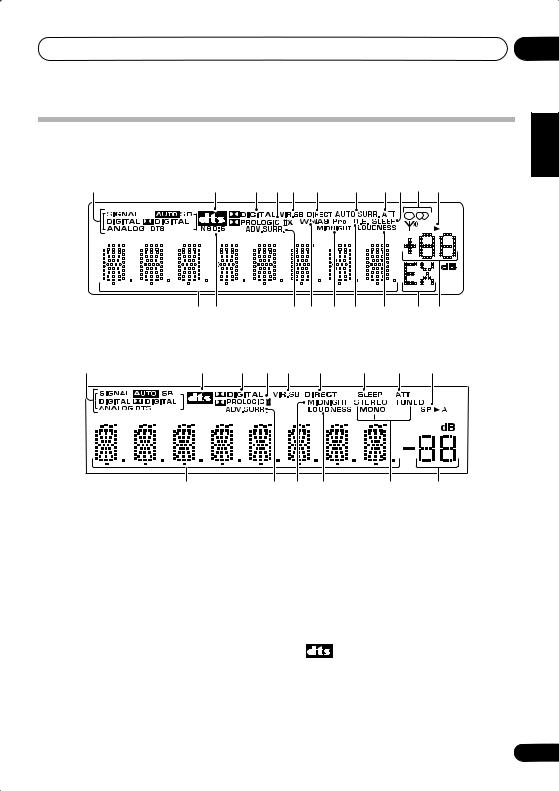
Controls and displays
Display
VSX-515 model:
1 |
2 |
3 |
4 |
5 |
6 |
7 |
8 |
9 |
10 |
11 |
04
English
SP |
A |
Deutsch |
12 13 |
14 15 |
16 |
17 |
18 |
19 |
20 |
Français
VSX-415 model: |
|
|
|
|
|
|
|
|
Italiano |
1 |
2 |
3 |
4 |
5 |
6 |
9 |
8 |
11 |
|
|
|
|
|
|
|
|
|
|
12 |
14 |
16 |
18 |
10 |
19 |
1 SIGNAL SELECT indicators |
|
|
2 DIGITAL |
|
|
Lights to indicate the type of input signal |
|
|
Lights when a Dolby Digital encoded signal |
||
assigned for the current component: |
|
|
is detected. |
|
|
AUTO |
|
|
ANALOG |
|
|
Lights when AUTO signal select is on. |
|
|
Lights when an analog signal is detected. |
||
SB |
|
|
DTS |
|
|
Depending on the source, this lights when |
|
|
Lights when a source with DTS encoded |
||
a signal with surround back channel |
|
|
audio signals is detected. |
|
|
encoding is detected. |
|
|
|
|
|
2
DIGITAL |
When the STANDARD mode of the receiver is |
|
Lights when a digital audio signal is |
||
on, this lights to indicate decoding of a DTS |
||
detected. |
||
multichannel signal. |
||
|
Español Nederlands
25
En

04 Controls and displays
3 2 DIGITAL
When the STANDARD mode of the receiver is on, this lights to indicate decoding of a Dolby Digital multichannel signal.
4 2 PRO LOGIC II x
When the (STANDARD) Pro Logic II mode of the receiver is on, 2 PRO LOGIC II lights to indicate Pro Logic II decoding.
VSX-515 model only – 2 PRO LOGIC II x lights to indicate Pro Logic IIx decoding (see
Listening in surround sound on page 29 for more on this).
5 VIR.SB
Lights during Virtual surround back processing (page 34).
6 DIRECT
Lights when source direct playback is in use. Direct playback bypasses the tone controls and channel levels for the most accurate reproduction of a source.
7AUTO SURR. (VSX-515 model only)
Lights when the Auto Surround feature is switched on (see Important on page 29).
8ATT
Lights when INPUT ATT is used to attenuate (reduce) the level of the analog input signal.
9 SLEEP
Lights when the receiver is in sleep mode (page 36).
10Tuner indicators
 / MONO
Lights when the mono mode is set using the MPX button.
 / STEREO
Lights when a stereo FM broadcast is being received in auto stereo mode.

 / TUNED
Lights when a broadcast is being received.
11 Speaker indicator
Shows if the speaker system is on or not. SP A means the speakers are switched on. SP means the headphones are connected.
12Character display
13Neo:6 (VSX-515 model only)
When the (STANDARD) Neo:6 mode of the receiver is on, this lights to indicate Neo:6 processing.
14ADV.SURR. (Advanced Surround)
Lights when one of the Advanced Surround modes has been selected.
15WMA9 Pro (VSX-515 model only)
Lights to indicate decoding of a WMA9 Pro signal.
16MIDNIGHT
Lights during Midnight listening (page 35).
17 D.E. (VSX-515 model only)
Lights when Dialog Enhancement (DIALOG E) is switched on (page 35).
18 LOUDNESS
Lights during Loudness listening (page 35).
19 EX
Lights when a Dolby Digital Surround EX encoded signal is detected.
20 Master volume level
Shows the overall volume level. ---dB indicates the minimum level, and - 0 dB indicates the maximum level.
Depending on your level settings for each channel, the maximum volume can range between –10 dB and –0 dB.
26
En
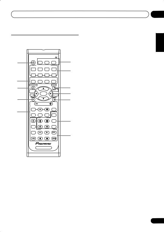
Controls and displays |
04 |
Remote control
Illustration shows the VSX-515 remote control
1 |
RECEIVER SLEEP FL DIMMER INPUT ATT |
6 |
||||
|
INPUT SELECTOR |
|
||||
|
|
|
|
|||
|
DVD/LD DVD 5.1CH |
TV/SAT |
DVR/VCR |
|
||
|
CD |
|
CD-R/ |
FM |
AM |
7 |
|
TAPE/MD |
|
||||
|
|
ADVANCED |
STEREO |
MIDNIGHT/ |
|
|
2 |
STANDARD SURROUND |
LOUDNESS |
|
|||
|
|
|
|
|
|
|
3 |
TOP MENU |
|
|
MENU |
8 |
|
SYSTEM |
|
|
|
|
||
|
|
|
|
RETURN |
|
|
|
SETUP |
|
ENTER |
|
9 |
|
|
DVD |
|
RECEIVER |
|||
|
|
|
|
|||
4 |
|
RECEIVER CONTROL |
|
10 |
||
|
|
|
|
|||
|
|
|
VOLUME |
|
|
|
|
EFFECT/CHSEL |
LEVEL |
MUTE |
|
||
5 |
DIALOGE |
|
SIGNAL |
TUNER |
CLASS |
|
|
SELECT |
EDIT |
|
|||
|
DVD |
|
TUNER |
MPX |
11 |
|
|
|
TUNING |
STATION DISPLAY |
|||
|
AUDIO |
|
||||
|
SUBTITLE |
|
DVD CONTROL |
|
||
|
|
|
|
|
|
12 |
|
|
RECEIVER |
|
|
||
1 |
RECEIVER |
|
|
|
|
|
Switches the receiver between standby and on.
2Listening mode buttons
STANDARD
Press for Standard decoding and to switch between the various Pro Logic II and Neo:6 options (page 29).
ADVANCED SURROUND
Use to switch between the various surround modes (page 30).
STEREO
Switches between direct and stereo playback. Direct playback bypasses the tone controls and channel levels for the most accurate reproduction of a source (page 32).
VSX-515 model only – Selects the Auto Surround mode(Important on page 29).
MIDNIGHT/LOUDNESS
Switches to Midnight or Loudness listening (page 35).
3TOP MENU
Displays the disc ‘top’ menu of a DVD.
SYSTEM SETUP (VSX-515 model only)
Press to access the System Setup menu (page 41).
TUNER EDIT (VSX-415 model only)
Press to memorize and name a station for recall (page 46).
4DVD
Press to use the DVD controls on the remote.
5RECEIVER CONTROL buttons
VOLUME +/–
Use to set the listening volume.
MUTE
Mutes/unmutes the sound.
VSX-515 model only:
EFFECT/CH SEL
Press repeatedly to select a channel, then use LEVEL +/– to adjust the level (page 43). Also adjusts the level of the Advanced Surround effects (page 30) as well as Dolby Pro Logic IIx Music (page 31) and Neo:6 Music parameters (page 32). You can then use the LEVEL +/– buttons to make these adjustments.
LEVEL +/–
Use to adjust the effect and channel levels, as well as to change Dolby Pro Logic IIx and Neo:6 Music parameter settings.
Español Nederlands Italiano Français Deutsch English
27
En

04 Controls and displays
DIALOG E
Use to make dialog stand out when watching TV or a movie (page 35).
SIGNAL SELECT
Use to select an input signal (page 32).
TUNER EDIT
Press to memorize and name a station for recall (page 46).
VSX-415 model only:
CH SELECT
Selects a speaker when setting up the surround sound of the receiver (page 40).
TEST TONE
Sounds the test tone when setting up the surround sound of the receiver (page 40).
LEVEL +/–
Adjusts the channel levels (page 40).
EFFECT +/–
Adds or subtracts the amount of effect with the advanced surround modes (page 30).
6SLEEP
Use to set the sleep timer (page 36).
FL DIMMER
Dims or brightens the display.
INPUT ATT
Attenuates (lowers) the level of an analog input signal to prevent distortion.
7INPUT SELECTOR buttons
Press to select an input source.
8MENU
Displays the disc menu of DVD-Video discs. It also displays TV menus.
RETURN (VSX-515 model only)
Confirm and exit the current menu screen.
9/ENTER
Use the arrow buttons when setting up your surround sound system (VSX-415 – page 37, VSX-515 – page 41). Also used for DVD menus.
28
10 RECEIVER
Use to switch to the receiver controls on the remote control. Also used when setting up the surround sound for the receiver (VSX-415 – page 37, VSX-515 – page 41).
11 TUNER controls
The TUNING +/– buttons can be used to find radio frequencies (page 46) and the STATION +/– buttons can be used to select preset radio stations (page 47).
CLASS
Switches between the three banks (classes) of station presets (page 46).
MPX
Use to switch between auto stereo and mono reception of FM broadcasts. If the signal is weak then switching to mono will improve the sound quality (page 46).
DISPLAY
Switch the display between station preset name and frequency (see tip on page 47).
12 DVD CONTROL buttons
You can use these buttons to control a Pioneer DVD player connected to your system.
Button What it does
DVD Turns DVD power on/off.
AUDIO Changes the audio language or channel.
SUBTITLE Displays/changes the subtitles on multilingual DVD-Video discs.
Starts/resumes normal playback.
Pauses/unpauses a disc.
Stops playback.
Press to start fast reverse scanning.
Press to start fast forward scanning.
Skips to the start of the current track or chapter, then previous tracks/chapters.
Skips to the next track or chapter.
En
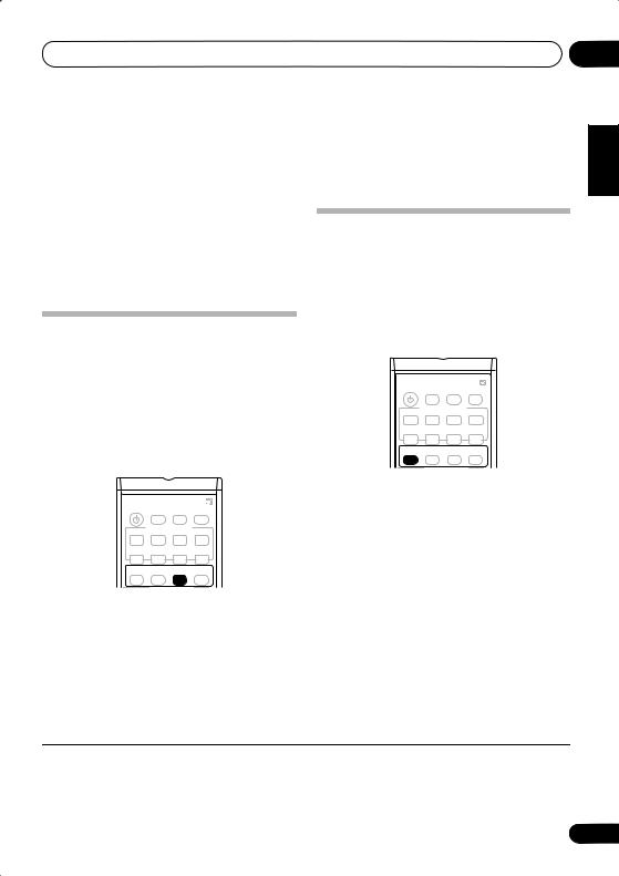
Listening to your system
Chapter 5:
Listening to your system
05
English
 Important
•Certain features explained in this section will not be possible depending on the source (for example, PCM 88.2 / 96kHz, DTS 96kHz (24 bit) or WMA 9 Pro sources).
Auto playback
VSX-515 model only
There are many ways to listen back to sources using this receiver, but for the simplest, most direct listening option is the Auto Surround feature. With this, the receiver automatically detects what kind of source you’re playing and selects multichannel or stereo playback as
necessary.1
Listening in surround sound
Using this receiver, you can listen to any source in surround sound. However, the options available will depend on your speaker setup and the type of source you’re listening to.
VSX-515 only – If you connected surround back speakers, see also Using the surround back channel (Extended mode) on page 33.
RECEIVER SLEEP FL DIMMER INPUT ATT
INPUT SELECTOR
DVD/LD DVD 5.1CH TV/SAT DVR/VCR
CD-R/ |
FM |
AM |
CD TAPE/MD |
||
ADVANCED |
STEREO |
MIDNIGHT/ |
STANDARD SURROUND |
LOUDNESS |
RECEIVER SLEEP FL DIMMER INPUT ATT
INPUT SELECTOR
DVD/LD DVD 5.1CH TV/SAT DVR/VCR
CD-R/ |
FM |
AM |
CD TAPE/MD |
||
ADVANCED |
STEREO |
MIDNIGHT/ |
STANDARD SURROUND |
LOUDNESS |
• While listening to a source, press STEREO for auto playback of a source.
Press repeatedly until AUTO SURR. shows briefly in the display (it will then show the decoding or playback format). Check the digital format indicators in the display to see how the source is being processed.
• While listening to a source, press STANDARD.
If the source is Dolby Digital, DTS, or Dolby Surround encoded, the proper decoding format will automatically be selected and
shows in the display.2
With two channel sources, press STANDARD repeatedly to select from:
•2 Pro Logic II MOVIE – Up to 5.1 channel sound, especially suited to movie sources
•2 Pro Logic II MUSIC – Up to 5.1 channel sound, especially suited to music sources
•2 PRO LOGIC – 5.1 channel surround sound
Español Nederlands Italiano Français Deutsch
 Note
Note
1• Stereo surround (matrix) formats are decoded accordingly using Neo:6 CINEMA or 2 Pro Logic IIx MOVIE (see Listening in surround sound above for more on these decoding formats).
•The Auto Surround feature is canceled if you connect headphones or select the multichannel analog inputs.
2VSX-515 model only – If the Extended mode (page 33) is switched to OFF, or the surround back speakers are set to NO (page 42), 2 Pro Logic IIx becomes 2 Pro Logic II (5.1 channel sound).
29
En
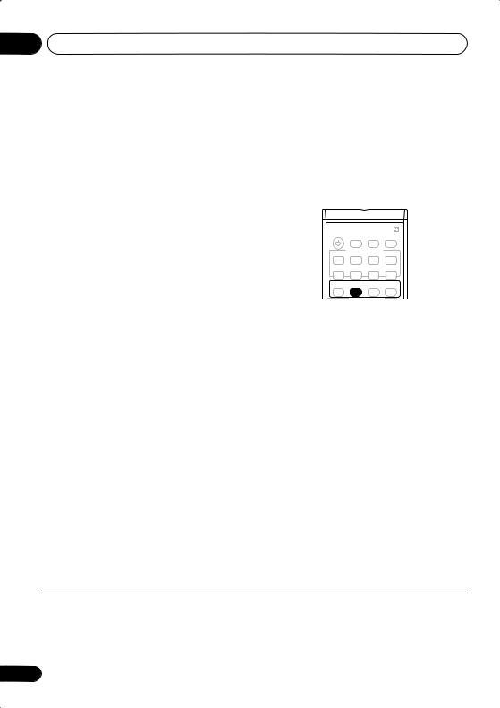
05 Listening to your system
VSX-515 model only:
•2 Pro Logic IIx MOVIE – Up to 7.1 channel sound, especially suited to movie sources
•2 Pro Logic IIx MUSIC – Up to 7.1 channel sound, especially suited to music sources
•2 Pro Logic IIx GAME – Up to 7.1 channel sound, especially suited for video games
•2 PRO LOGIC – 5.1 channel surround sound
•Neo:6 CINEMA – 6.1 channel sound, especially suited to movie sources
•Neo:6 MUSIC – 6.1 channel sound, especially suited to music sources
VSX-515 model only – With multichannel sources, if you have connected surround back
speaker(s) and have selected Extended ON1, you can select (according to format):
•2 Pro Logic IIx MUSIC – See above (only available when you’re using two surround back speakers)
•Dolby Digital EX – Creates surround back channel sound for 5.1 channel sources and provides pure decoding for 6.1 channel sources (like Dolby Digital Surround EX)
•DTS-ES – Allows you to hear 6.1 channel playback with DTS encoded sources
Using the Advanced surround effects
The Advanced surround effects can be used for a variety of additional surround sound effects. Most Advanced Surround modes are designed to be used with film soundtracks, but some modes are also suited for music sources. Try different settings with various soundtracks to
see which you like.2
RECEIVER SLEEP FL DIMMER INPUT ATT
INPUT SELECTOR
DVD/LD DVD 5.1CH TV/SAT DVR/VCR
CD-R/ |
FM |
AM |
CD TAPE/MD |
||
ADVANCED |
STEREO |
MIDNIGHT/ |
STANDARD SURROUND |
LOUDNESS |
• Press ADVANCED SURROUND repeatedly to select a listening mode.
•ADV. MOVIE – Simulates the relaxed environment of a movie theater, and is suitable for watching movies.
•ADV. MUSIC – Simulates the acoustic environment of a large concert hall and is suitable for music or musical sources.
•TV SURR. – This mode produces surround sound for both mono and stereo TV sources. It is useful for older movies recorded with mono soundtracks.
•SPORTS – This is designed for sports programs with a lot of action, adding to the excitement by bringing background action to the forefront.
•ADV. GAME – Useful when playing video games. It works especially well with sound moving from left to right in game software with a lot of movement.
 Note
Note
1During playback of a Dolby Digital multichannel source with the Extended mode switched ON, you will only be able to select
Dolby Digital EX or 2Pro Logic IIx MUSIC. See Using the surround back channel (Extended mode) on page 33 for more on this.
2• If you press ADVANCED SURROUND when the headphones are connected, the PHONES SURROUND mode will automatically be selected.
•VSX-515 model only – Depending on the source and the sound mode you have selected, you may not get sound from the surround back speakers in your setup. For more on this, refer to Using the surround back channel (Extended mode) on page 33.
30
En
 Loading...