


Pioneer CB009GMFILCFHD, RB009GMFILCFHD, FB009GMFILCFHD, CB012GMFILCFHD, RB012GMFILCFHD SERVICE MANUAL
...LIGHT COMMERCIAL SPLIT SYSTEMS
3D DC INVERTER HEAT PUMP
SERVICE MANUAL |
Single Zone |
ALL RIGHTS RESERVED. PARKER DAVIS HVAC INTERNATIONAL, INC., DORAL, FL 33172 USA
Phone: (800) 243-0340 www.highseer.com
Revision A: 1605, Content updated.
Table of Contents |
Model Numbers: |
|
|
|
|
|
|
|
1. |
Precaution |
Indoor Unit Model Numbers: |
|
|
|
|
||
2. |
Part Names And Functions |
Ceiling Cassette |
|
Concealed Ducted |
|
Floor, Ceiling, Low Wall |
||
3. |
Dimension |
CB009GMFILCFHD |
|
RB009GMFILCFHD |
|
FB009GMFILCFHD |
|
|
4. |
Service space |
CB012GMFILCFHD |
|
RB012GMFILCFHD |
|
FB012GMFILCFHD |
|
|
5. |
Refrigerant Cycle Diagram |
CB018GMFILCFHD |
|
RB018GMFILCFHD |
|
UB018GMFILCFHD |
|
|
6. |
Wiring Diagram |
CB024GMFILCFHD |
|
RB024GMFILCFHD |
|
UB024GMFILCFHD |
|
|
7. |
Static Pressure |
|
|
|
|
|
||
CB036GMFILCFHD |
|
RB036GMFILCFHD |
|
UB036GMFILCFHD |
|
|||
8. |
Electric Characteristics |
CB048GMFILCFHD |
|
RB048GMFILCFHD |
|
UB048GMFILCFHD |
|
|
9.Sound Level
10. |
Accessories |
Outdoor Unit: |
|
|
|
11. |
The Specification of Power |
Standard Communication Circuit Models: |
|
||
12. |
Installation Details |
YN009GMFI22RPD |
YN012GMFI22RPD |
YN018GMFI22RPD |
|
13. |
Operation Characteristics |
YN024GMFI22RPD |
|
|
|
14. |
Electronic Function |
RS 485 Communication Circuit Models: |
|
||
15. |
Solar Panel |
YN036GMFI17RUD |
YN038GMFI17RUD |
|
|
16.Troubleshooting
17.Disassembly Instructions
WARNING
Installation MUST conform with local building codes or, in the absence of local codes, with the National Electrical Code NFPA70/ANSI C1-1993 or current edition and Canadian Electrical Code Part1 CSA C.22.1.
The information contained in the manual is intended for use by a qualified service technician familiar with safety procedures and equipped with the proper tools and test instruments
Installation or repairs made by unqualified persons can result in hazards to you and others.
Failure to carefully read and follow all instructions in this manual can result in equipment malfunction, property damage, personal injury and/or death.
This service is only for service engineer to use.
|
|
|
CONTENTS |
|
1. Precaution.................................................................................................................................................. |
1 |
|||
1.1 |
Safety Precaution ....................................................................................................................... |
1 |
||
1.2 |
Warning ...................................................................................................................................... |
1 |
||
2. Part Names and Features.......................................................................................................................... |
4 |
|||
2.1 |
Model Names of Indoor/Outdoor units........................................................................................ |
4 |
||
2.2 |
Part names of Indoor/Outdoor units............................................................................................ |
5 |
||
2.3 |
Features ..................................................................................................................................... |
9 |
||
3. Dimension................................................................................................................................................ |
18 |
|||
3.1 |
Indoor Unit................................................................................................................................ |
18 |
||
3.2 |
Outdoor Unit ............................................................................................................................. |
23 |
||
4. Service Space .......................................................................................................................................... |
24 |
|||
4.1 |
Indoor Unit................................................................................................................................ |
24 |
||
4.2 |
Outdoor Unit ............................................................................................................................. |
26 |
||
5. Refrigerant Cycle Diagram...................................................................................................................... |
27 |
|||
6. Wiring Diagram........................................................................................................................................ |
28 |
|||
6.1 |
Indoor Unit................................................................................................................................ |
28 |
||
6.2 |
Outdoor Unit ............................................................................................................................. |
34 |
||
7. Fan Curves............................................................................................................................................... |
40 |
|||
8 Electric Characteristics............................................................................................................................ |
47 |
|||
9 Sound Level.............................................................................................................................................. |
48 |
|||
9.1 |
Indoor unit ................................................................................................................................ |
48 |
||
9.2 |
Outdoor unit.............................................................................................................................. |
51 |
||
10 Accessories ............................................................................................................................................ |
52 |
|||
11 The Specification of Power.................................................................................................................... |
54 |
|||
12 Installation Details.................................................................................................................................. |
56 |
|||
12.1 |
|
Location selection ............................................................................................................... |
56 |
|
12.2 |
|
Indoor unit installation......................................................................................................... |
56 |
|
12.3 |
|
Outdoor unit installation ...................................................................................................... |
61 |
|
12.4 |
|
Refrigerant pipe installation ................................................................................................ |
62 |
|
12.5 |
|
Drainage pipe installation.................................................................................................... |
66 |
|
12.6 |
|
Vacuum Drying and Leakage Checking .............................................................................. |
69 |
|
12.7 |
|
Additional refrigerant charge............................................................................................... |
70 |
|
12.8 |
|
Engineering of insulation..................................................................................................... |
71 |
|
12.9 |
|
Engineering of electrical wiring ........................................................................................... |
72 |
|
12.10 |
Test operation.................................................................................................................. |
72 |
||
13. Operation Characteristics..................................................................................................................... |
74 |
|||
14. Electronic Function............................................................................................................................... |
75 |
|||
14.1 Abbreviation............................................................................................................................ |
75 |
|||
14.2 |
Display function ...................................................................................................................... |
75 |
||
14.3 |
Main Protection....................................................................................................................... |
75 |
||
14.4 |
Operation Modes and Functions............................................................................................. |
76 |
||
16. Troubleshooting .................................................................................................................................... |
82 |
|||
16.1 |
Indoor Unit Error Display ........................................................................................................ |
83 |
||
16.2 |
Outdoor unit error display ....................................................................................................... |
84 |
||
For 9K-24K outdoor unit: ................................................................................................................ |
84 |
|
For 36K-48K Outdoor Unit.............................................................................................................. |
85 |
|
Outdoor check function................................................................................................................... |
86 |
|
16.3 |
Diagnosis and Solution........................................................................................................... |
88 |
16.4 |
Main parts check .................................................................................................................. |
102 |
17. Disassembly Instructions ................................................................................................................... |
109 |
|
17.1 |
Indoor unit ............................................................................................................................ |
109 |
17.2 |
Outdoor unit.......................................................................................................................... |
126 |
1.Precaution
1.1Safety Precaution
To prevent injury to the user or other people and property damage, the following instructions must be followed.
Incorrect operation due to ignoring instruction will cause harm or damage.
Before service the unit, be sure to read this service manual at first.
1.2Warning
Installation
Do not use a defective or underrated
circuit breaker. Use this appliance on a dedicated circuit.
There is risk of fire or electric shock.
For electrical work, contact the dealer, seller, a qualified electrician, or an authorized service center.
Do not disassemble or repair the product, there is risk of fire or electric shock.
Always ground the product.
There is risk of fire or electric shock.
Install the panel and the cover of control box securely.
There is risk of fire of electric shock.
Always install a dedicated circuit and breaker.
Improper wiring or installation may cause electric shock.
Use the correctly rated breaker of
fuse.
There is risk of fire or electric shock.
Do not modify or extend the power
cable.
There is risk of fire or electric shock.
Do not install, remove, or reinstall the unit by yourself (customer).
There is risk of fire, electric shock, explosion, or injury.
1
Be caution when unpacking and installing the product.
Sharp edges could cause injury, be especially careful of the case edges and the fins on the condenser and evaporator.
For installation, always contact the dealer or an authorized service center.
Do not install the product on a defective installation stand.
Be sure the installation area does not deteriorate with age.
If the base collapses, the air conditioner could fall with it, causing property damage, product failure, and personal injury.
Do not let the air conditioner run for a long time when the humidity is very high and a door or a window is left open.
Take care to ensure that power cable could not be pulled out or damaged during operation.
There is risk of fire or electric shock.
Do not place anything on the power
cable.
There is risk of fire or electric shock.
Do not plug or unplug the power supply plug during operation.
There is risk of fire or electric shock.
Do not touch (operation) the product with wet hands.
Do not place a heater or other appliance near the power cable.
There is risk of fire and electric shock.
Do not allow water to run into electrical parts.
It may cause fire, failure of the product, or electric shock.
Do not store or use flammable gas or combustible near the product.
There is risk of fire or failure of product.
Do not use the product in a tightly closed space for a long time.
Oxygen deficiency could occur.
When flammable gas leaks, turn off the gas and open a window for ventilation before turn the product on.
If strange sounds or smoke comes from product, turn the breaker off or disconnect the power supply cable.
There is risk of electric shock or fire.
Stop operation and close the window in storm or hurricane. If possible, remove the product from the window before the hurricane arrives.
There is risk of property damage, failure of product, or electric shock.
Do not open the inlet grill of the product during operation. (Do not touch the electrostatic filter, if the unit is so equipped.)
There is risk of physical injury, electric shock, or product failure.
When the product is soaked, contact an authorized service center.
There is risk of fire or electric shock.
Be caution that water could not enter the product.
There is risk of fire, electric shock, or product damage.
Ventilate the product from time to time when operating it together with a stove etc.
There is risk of fire or electric shock.
Turn the main power off when cleaning or maintaining the product.
There is risk of electric shock.
When the product is not be used for a long time, disconnect the power supply plug or turn off the breaker.
There is risk of product damage or failure, or unintended operation.
Take care to ensure that nobody could step on or fall onto the outdoor unit.
This could result in personal injury and product damage.
CAUTION
Always check for gas (refrigerant)
leakage after installation or repair of product.
Low refrigerant levels may cause failure of product.
2
Install the drain hose to ensure that water is drained away properly.
A bad connection may cause water leakage.
Keep level even when installing the product.
It can avoid vibration of water leakage.
Do not install the product where the noise or hot air from the outdoor unit could damage the neighborhoods.
It may cause a problem for your neighbors.
Use two or more people to lift and transport the product.
Do not install the product where it will be exposed to sea wind (salt spray) directly.
It may cause corrosion on the product. Corrosion, particularly on the condenser and evaporator fins, could cause product malfunction or inefficient operation.
Operational
Do not expose the skin directly to
cool air for long time. (Do not sit in the draft).
Do not use the product for special purposes, such as preserving foods, works of art etc. It is a consumer air conditioner, not a precision refrigerant system.
There is risk of damage or loss of property.
Do not block the inlet or outlet of air
flow.
Use a soft cloth to clean. Do not use harsh detergents, solvents, etc.
There is risk of fire, electric shock, or damage to the plastic parts of the product.
Do not touch the metal parts of the product when removing the air filter. They are very sharp.
Do not step on or put anything on the product. (outdoor units)
Always insert the filter securely. Clean the filter every two weeks or more often if necessary.
A dirty filter reduces the efficiency of the air conditioner and could cause product malfunction or damage.
Do not insert hands or other objects through air inlet or outlet while the product is operated.
Do not drink the water drained from the product.
Use a firm stool or ladder when cleaning or maintaining the product.
Be careful and avoid personal injury.
Replace the all batteries in the remote control with new ones of the same type. Do not mix old and new batteries or different types of batteries.
There is risk of fire or explosion.
Do not recharge or disassemble the batteries. Do not dispose of batteries in a fire.
They may burn of explode.
If the liquid from the batteries gets onto your skin or clothes, wash it well with clean water. Do not use the remote of the batteries have leaked.
3
2.Part Names and Features
2.1Model Names of Indoor/Outdoor units
Series |
Capacity |
Indoor units |
Outdoor units |
|
|
|
|
Cassette |
|
CB009GMFILCFHD |
|
|
|
|
|
Duct |
9K |
RB009GMFILCFHD |
YN009GMFI22RPD |
|
|
|
|
Console |
|
FB009GMFILCFHD |
|
|
|
|
|
Cassette |
|
CB012GMFILCFHD |
|
|
|
|
|
Duct |
12K |
RB012GMFILCFHD |
YN012GMFI22RPD |
|
|
|
|
Console |
|
FB012GMFILCFHD |
|
|
|
|
|
Cassette |
|
CB018GMFILCFHD |
|
|
|
|
|
Duct |
18K |
RB018GMFILCFHD |
YN018GMFI22RPD |
|
|
|
|
Floor Ceiling |
|
UB018GMFILCFHD |
|
|
|
|
|
Cassette |
|
CB024GMFILCFHD |
|
|
|
|
|
Duct |
24K |
RB024GMFILCFHD |
YN024GMFI22RPD |
|
|
|
|
Floor Ceiling |
|
UB024GMFILCFHD |
|
|
|
|
|
Cassette |
|
CB036GMFILCFHD |
|
|
|
|
|
Duct |
36K |
RB036GMFILCFHD |
YN036GMFI17RUD |
|
|
|
|
Floor Ceiling |
|
UB036GMFILCFHD |
|
|
|
|
|
Cassette |
|
CB048GMFILCFHD |
|
|
|
|
|
Duct |
48K |
RB048GMFILCFHD |
YN048GMFI17RUD |
|
|
|
|
Floor Ceiling |
|
UB048GMFILCFHD |
|
|
|
|
|
4
2.2 Part names of Indoor/Outdoor units
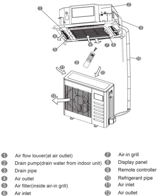
Ceiling Cassette Unit
5
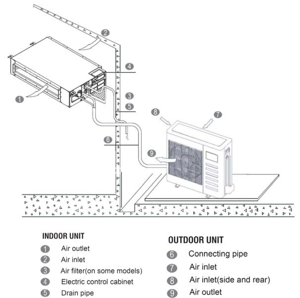
Ducted Concealed Units
6
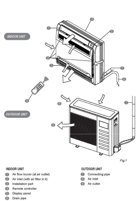
Floor Console Units
7
Ceiling-Floor Units
8
2.3 Features
2.3.1 Duct Units
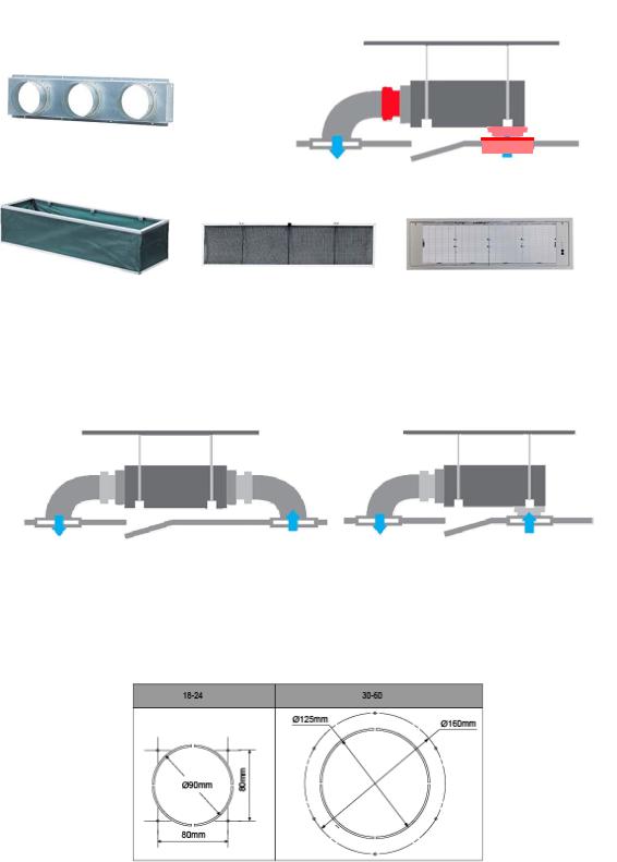
2.3.1.1 Installation accessories: (Field Supplied / Optional)
Front Board, Canvas Air Passage, Filter, Panel, for easy installation
Panel
2.3.1.2 Easy Installation: Two air inlet styles (Bottom side or Rear side)
Air inlet from rear is standard for all capacity; air inlet from bottom is optional.
The size of air inlet frame from rear and bottom is same, it’s very easy to move the cover from bottom to rear side, or from rear to the bottom, in order to matching the installation condition.
Air intake from rear (Standard) |
|
Air intake from bottom (Optional) |
|
|
|
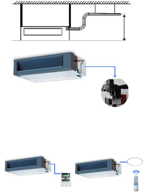
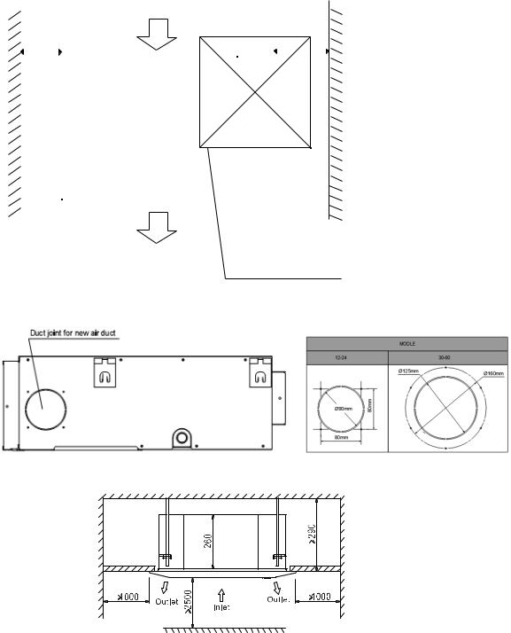
2.3.1.3 Fresh air intake function
Install one duct from the reserved fresh-air intake to outdoor.
Continually inhale the fresh air to improve the quality of the indoor air, fulfills air quality more healthy and comfortable.
9

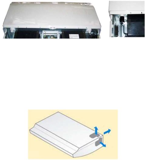
2.3.1.4 Easy maintenance
Clean the filter (Optional, standard product without filter)
It is easy to draw out the filter from the indoor unit for cleaning, even the filter is installed in rear side or bottom side.
Replace the motor or centrifugal fan
Remove the ventilated panel firstly. Remove a half of blower housing and take out the motor with centrifugal fan. Directly remove two bolts, and then replace the motor or centrifugal fan easily.
Motor
Blower Housing
Ventilated Panel
2.3.1.5 Reserved remote on-off and central control ports
Reserved remote on-off ports and central control ports, can connect the cable of an on-off controller or a central controller to realize remote on-off control function or group control function.
Remote on-off ports |
Central control ports |
2.3.1.6 Built-in drain pump (Optional):
Built-in drain pump can lift the water to 750mm upmost. It’s convenient to install drainage piping under most space condition.
10
2.3.2.7 Build-in Drain Pump with float switch
The drain pump can lift the condensing water up to 750mm upmost.
It’s convenient to install drainage piping under most space condition.
<![if ! IE]><![endif]>750mm upmost
2.3.1.8 Built-in display board
The standard indoor unit can be controlled by wired controller.
There is a display board with a receiver in the E-box. Move out the display, and fix it in other place, even in the distance of 10m. The unit will realized remoter control.
The wired controller and the display board can display the error code or production code when the chips detect some failure.
Wired Controller (Standard) |
Remote Controller (Optional) |
Display
11
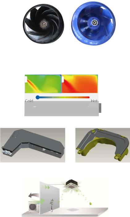
2.3.2 Cassette Unit
2.3.2.1 Lower Noise
Optimize air channel system design to ensure the maximum quietness and comfort.
Noise max down 6dB.
Old |
New |
2.3.2.2 Turbo mode (Optional)
Turbo function can boost cooling or heating speed in a short period, and makes the room cool down or heat up rapidly.
Common vs. Turbo
Turbo Mode (After 30 min)
2.3.2.3 Fire-proof controller box
Electrical control box adopts new design, which can meet higher fire safety requirements.
New |
Old |
2.3.2.4 Fresh Air
Fresh air intake function bring you fresh and comfortable air feeling.
2.3.2.5 Wired controller (Optional)
Compared with infrared remote controller, wired controller can be fixed on the wall and avoid mislaying. It's mainly used for commercial zone and makes air conditioner control more convenient.
12
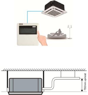
2.3.2.6 Build-in Drain Pump
The drain pump can lift the condensing water up to 750mm upmost.
It’s convenient to install drainage piping under most space condition.
2.3.2.7Terminals for alarm lamp and long-distance on-off controller connection are standard
Reserve terminals for the connection of alarm lamp and long-distance on-off controller, more human control.
13
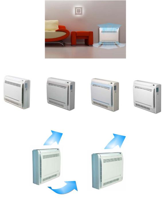
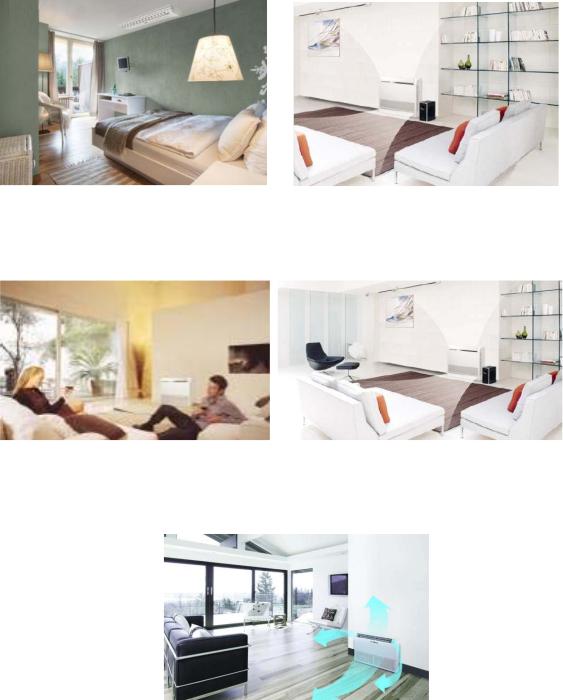
2.3.3 Console
2.3.3.1. Modern and elegant appearance
The simple and stylish designs can nicely harmonies with your living space.
3.2.3.2. Four panels optional
2.3.3.3. Two air-outlet ways Cooling mode
Quick Cooling |
To maintain room temp |
Air outlet from top and bottom to make quick cooling ------When the A/C is just switched on, or room temp. is still high, cold air will be blown out from top and bottom air outlet to cool down the room quickly
Air outlet from top to maintain room temp. ----When the room has been cooled down, or the A/C has been opened over 1 hour, cold air only from the top outlet to keep constant room temp
14
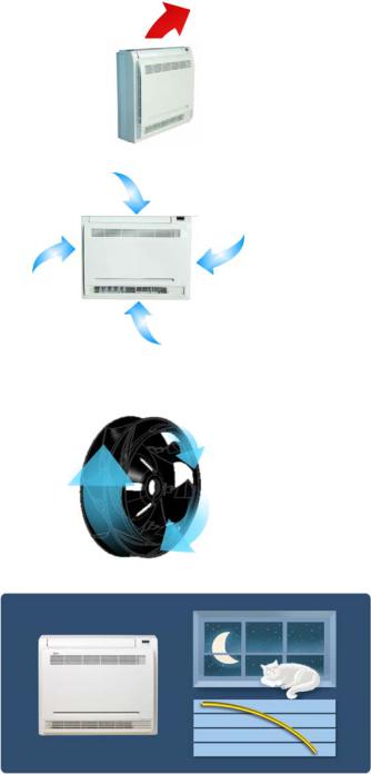
Heating mode
Anti-cold air ------When the AC is just turn on, temperature of evaporator is very low, in this case, in order to prevent cold air direct blowing, only the upper louver is opened in a high position, the lower louver closed.
2.3.3.4. Four air inlets
2.3.3.5. Low noise
DC indoor fan motor, which has five speeds.
Low noise and energy saving.
Advanced centrifugal fan technology makes a fast airflow and reduces the indoor noise.
2.3.3.6.Golden fin is optional.
2.3.3.7.Active carbon filter is standard
15
2.3.1 Ceiling-floor Units
2.3.1.1 Two-way installation
The rounded design of the ceiling and floor type air conditioner allows either ceiling or floor-level installation. Ceiling installation saves room space, while floor installation helps prevent the loss of warm air.
2.3.1.2 Brief design
Brief design that is suitable for any interior will not only give you cooling and heating performance but also upgrade your lifestyle.
2.3.1.3 3D airflow
Vertical air flow and horizontal airflow can be adjusted by remote controller, the cooperation of the two airflow ways help to spread air comfortably throughout even a large room. With these functions, the whole room can be evenly air-conditioned for both floor-level and ceiling installation.
16
2.3.1.4 Optional drainage pipe connection
Both right side and left side drainage holes are available to avoid the space limitation for drainage pipe installation. Make you more convenient during installation.
C Panel (LED display) |
D Panel |
2.3.1.5 Convenience operating and easy maintenance
Remote controller as standard, wired controller for optional.
The filter without screw fixed, can be took out easily.
2.3.1.6 Easy installation, save working time
The pipes can be connected from bottom, back and right side, makes the installation more easily.
The wiring works can be finished before installation.
2.3.1.7 Outside water pump for optional when ceiling installation.
17
3. Dimension
3.1 Indoor Unit
Duct Units
Air filter ( optional ) |
air inlet from rear side |
|
|
|
<![if ! IE]> <![endif]>J |
|
H2 |
|
H1 |
| <![if ! IE]> <![endif]>W2 |
<![if ! IE]> <![endif]>W1 |
Test mouth & Test cover |
|
25 Drain connecting pipe |
|
( for pump ) |
|
|
|
I |
|
|
4-install hanger |
|
L |
|
B |
|
A |
Liquid side |
|
|
|
|
|
||
|
|
|
|
|
25 Drain pipe |
|
|
Gas side |
|
| <![if ! IE]> <![endif]>M |
|
|
25 Drain pipe |
|
|
|
|
<![if ! IE]> <![endif]>D C |
|
|
|
|
|
|
|
|
|
Electric control box |
Fresh air intake |
| <![if ! IE]> <![endif]>G |
E |
F |
|
|
| <![if ! IE]> <![endif]>H |
|
|
|
|
Air filter ( optional )
K


 air inlet from bottom side
|
|
Outline dimension(mm) |
Air outlet opening size |
Air return opening size |
Size of install |
Size of refrigerant pipe |
|||||||||||||
Capacity (KBtu) |
hanger |
||||||||||||||||||
|
|
|
|
|
|
|
|
|
|
|
|
|
|
|
|||||
|
|
|
|
|
|
|
|
|
|
|
|
|
|
|
|
|
|
|
|
|
|
A |
B |
C |
D |
E |
F |
G |
H |
I |
J |
K |
L |
M |
H1 |
H2 |
W1 |
W2 |
|
|
|
|
|
|
|
|
|
|
|
|
|
|
|
|
|
|
|
|
|
9 |
mm |
700 |
210 |
635 |
570 |
65 |
493 |
35 |
119 |
595 |
200 |
80 |
740 |
350 |
120 |
143 |
95 |
150 |
|
|
|
|
|
|
|
|
|
|
|
|
|
|
|
|
|
|
|
||
in |
27.56 |
8.27 |
25 |
22.44 |
2.56 |
19.41 |
1.38 |
4.69 |
23.43 |
7.87 |
3.15 |
29.13 |
13.78 |
4.72 |
5.63 |
3.74 |
5.91 |
||
|
|||||||||||||||||||
|
|
|
|
|
|
|
|
|
|
|
|
|
|
|
|
|
|
|
|
12 |
mm |
700 |
210 |
635 |
570 |
65 |
493 |
35 |
119 |
595 |
200 |
80 |
740 |
350 |
120 |
143 |
95 |
150 |
|
|
|
|
|
|
|
|
|
|
|
|
|
|
|
|
|
|
|
||
in |
27.56 |
8.27 |
25 |
22.44 |
2.56 |
19.41 |
1.38 |
4.69 |
23.43 |
7.87 |
3.15 |
29.13 |
13.78 |
4.72 |
5.63 |
3.74 |
5.91 |
||
|
|||||||||||||||||||
|
|
|
|
|
|
|
|
|
|
|
|
|
|
|
|
|
|
|
|
18 |
mm |
920 |
210 |
635 |
570 |
65 |
713 |
35 |
119 |
815 |
200 |
80 |
960 |
350 |
120 |
143 |
95 |
150 |
|
|
|
|
|
|
|
|
|
|
|
|
|
|
|
|
|
|
|
||
in |
36.22 |
8.27 |
25.00 |
22.44 |
2.56 |
28.07 |
1.38 |
4.69 |
32.09 |
7.87 |
3.15 |
37.80 |
13.78 |
4.72 |
5.63 |
3.74 |
5.91 |
||
|
|||||||||||||||||||
|
|
|
|
|
|
|
|
|
|
|
|
|
|
|
|
|
|
|
|
24 |
mm |
920 |
270 |
635 |
570 |
65 |
713 |
35 |
179 |
815 |
260 |
20 |
960 |
350 |
120 |
143 |
95 |
150 |
|
|
|
|
|
|
|
|
|
|
|
|
|
|
|
|
|
|
|
||
in |
36.22 |
10.63 |
25.00 |
22.44 |
2.56 |
28.07 |
1.38 |
7.05 |
32.09 |
10.24 |
0.78 |
37.80 |
13.78 |
4.72 |
5.63 |
3.74 |
5.91 |
||
|
|||||||||||||||||||
|
|
|
|
|
|
|
|
|
|
|
|
|
|
|
|
|
|
|
|
36 |
mm |
1140 |
270 |
775 |
710 |
65 |
933 |
35 |
179 |
1035 |
260 |
20 |
1180 |
490 |
120 |
143 |
95 |
150 |
|
|
|
|
|
|
|
|
|
|
|
|
|
|
|
|
|
|
|
||
in |
44.88 |
10.63 |
30.51 |
27.95 |
2.56 |
36.73 |
1.38 |
7.05 |
40.75 |
10.24 |
0.78 |
46.46 |
19.29 |
4.72 |
5.63 |
3.74 |
5.91 |
||
|
|||||||||||||||||||
|
|
|
|
|
|
|
|
|
|
|
|
|
|
|
|
|
|
|
|
48 |
mm |
1200 |
300 |
865 |
800 |
80 |
968 |
40 |
204 |
1094 |
288 |
45 |
1240 |
500 |
175 |
198 |
155 |
210 |
|
|
|
|
|
|
|
|
|
|
|
|
|
|
|
|
|
|
|
||
in |
47.24 |
11.81 |
34.06 |
31.50 |
3.15 |
38.11 |
1.57 |
8.03 |
43.07 |
11.34 |
1.77 |
48.82 |
19.69 |
6.89 |
7.80 |
6.10 |
8.27 |
||
|
|||||||||||||||||||
|
|
|
|
|
|
|
|
|
|
|
|
|
|
|
|
|
|
|
|
18
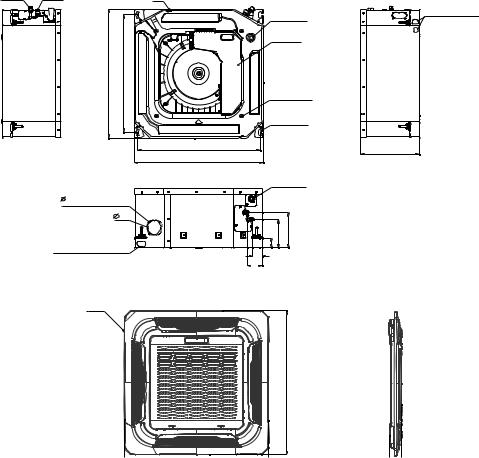
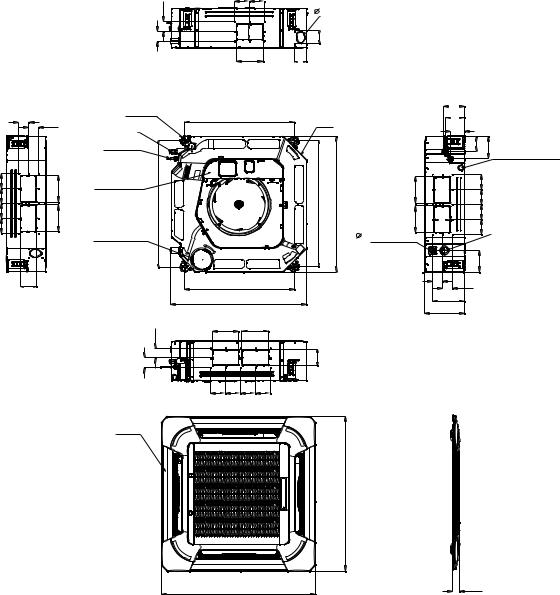
Cassette Units (9K, 12K, 18K)
Liquid side |
Gas side |
|
Body |
| <![if ! IE]> <![endif]>570 |
<![if ! IE]> <![endif]>523 |
|
545 |
|
570 |
Drain hole
( for Service )
E-parts box
4-Screw hole (for install panel)
4-install hanger
 32 Drain pipe
65 Fresh air intake |
|
|
75 |
|
|
|
<![if ! IE]> <![endif]>126 157 |
|
Wiring connection port |
<![if ! IE]> <![endif]>44 |
|
42 |
||
|
||
|
68 |
|
Panel |
|
<![endif]>647
Wiring connection port
260
19
Cassette Units (24K, 36K, 48K)
| <![if ! IE]> <![endif]>D |
92 |
92 |
|
75 Fresh air intake |
|
|
|
|
| <![if ! IE]> <![endif]>D |
<![if ! IE]> <![endif]>B |
<![if ! IE]> <![endif]>80 |
|
A |
80 |
|
D |
D |
|
|
|
| <![if ! IE]> <![endif]>92 |
|
<![if ! IE]> <![endif]>A |
| <![if ! IE]> <![endif]>92 |
|
|
| <![if ! IE]> <![endif]>92 |
|
<![if ! IE]> <![endif]>A |
| <![if ! IE]> <![endif]>92 |
|
|
|
B |
|
4-install hanger |
680 |
|
|
|
Gas side |
|
Body |
||
|
|
|
||
|
|
|
|
|
Liquid side |
|
|
|
|
E-parts box |
|
|
|
|
| <![if ! IE]> <![endif]>780 |
|
|
<![if ! IE]> <![endif]>780 |
<![if ! IE]> <![endif]>840 |
Service hole for |
|
|
|
|
draining pump |
|
|
|
|
|
680 |
|
|
|
|
840 |
|
|
|
| <![if ! IE]> <![endif]>D |
A |
|
A |
|
|
|
|
|
|
| <![if ! IE]> <![endif]>D |
|
|
<![if ! IE]> <![endif]>B |
|
92 |
92 |
92 |
92 |
|
|
136 |
|
|
|
126 |
|
|
|
91 |
|
|
|
|
<![if ! IE]> <![endif]>90 135 |
Wiring connection port |
| <![if ! IE]> <![endif]>A |
|
<![if ! IE]> <![endif]>92 |
|
|
<![if ! IE]> <![endif]>92 |
|
|
|
|
|
|
| <![if ! IE]> <![endif]>A |
B |
<![if ! IE]> <![endif]>92 |
|
|
|
||
32 Drain hole |
|
<![if ! IE]> <![endif]>92 |
Test mouth & Test cover |
|
|
|
|
|
|
<![if ! IE]> <![endif]>132 |
|
|
D |
D |
|
|
|
|
|
|
196 |
|
|
|
C |
|
|
Panel
|
<![if ! IE]> <![endif]>950 |
950 |
55 |
|
Capacity (Btu/h) |
|
A |
B |
C |
D |
|
|
|
|
|
|
|
|
24K |
mm |
160 |
75 |
205 |
50 |
|
|
|
|
|
|
||
inch |
6.30 |
2.95 |
8.07 |
1.97 |
||
|
||||||
|
|
|
|
|
|
|
36K |
mm |
160 |
95 |
245 |
60 |
|
|
|
|
|
|
||
inch |
6.30 |
3.74 |
9.65 |
2.36 |
||
|
||||||
|
|
|
|
|
|
|
48K |
mm |
160 |
95 |
287 |
60 |
|
|
|
|
|
|
||
inch |
6.30 |
3.74 |
11.30 |
2.36 |
||
|
||||||
|
|
|
|
|
|
20
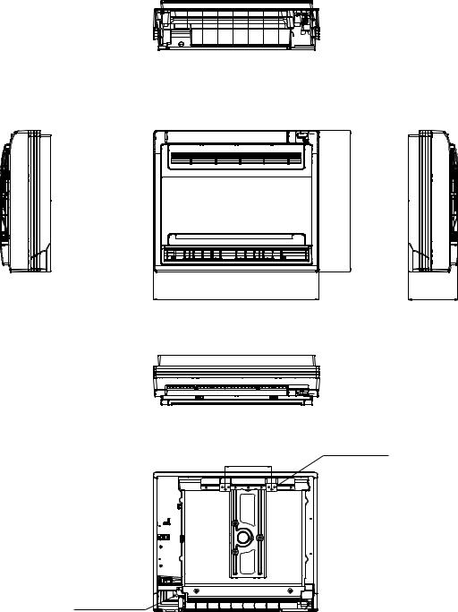
Console Units
|
<![if ! IE]> <![endif]>600 |
700 |
210 |
195
 16 Drain pipe
Hanging arm
Unit: mm
21
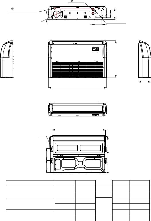
Ceiling-floor Units (18K-48K)
2- |
33 |
Wiring connection port
2- |
40 |
 120
120
Drain discharge port |
|
|
<![if ! IE]> <![endif]>140 |
<![if ! IE]> <![endif]>204 |
Fresh air intake |
<![if ! IE]> <![endif]>94 |
|
||
|
120 |
Refrigerant pipe hole |
||
|
|
|||
|
|
|
|
|
<![endif]>B
C
A
|
|
D |
|
|
|
|
Hanging arm |
|
|
|
|
|
|
| <![if ! IE]> <![endif]>220 |
|
|
|
|
|
|
| <![if ! IE]> <![endif]>222 |
|
|
|
|
|
|
Capacity (Btu/h) |
|
A |
B |
C |
D |
|
18K / 24K |
mm |
1068 |
675 |
235 |
983 |
|
inch |
42.05 |
26.57 |
9.25 |
38.70 |
||
|
||||||
36K |
mm |
1285 |
675 |
235 |
1200 |
|
inch |
50.59 |
26.57 |
9.25 |
47.24 |
||
|
||||||
48K |
mm |
1650 |
675 |
235 |
1565 |
|
inch |
64.96 |
26.57 |
9.25 |
61.61 |
||
|
||||||
|
|
22 |
|
|
|
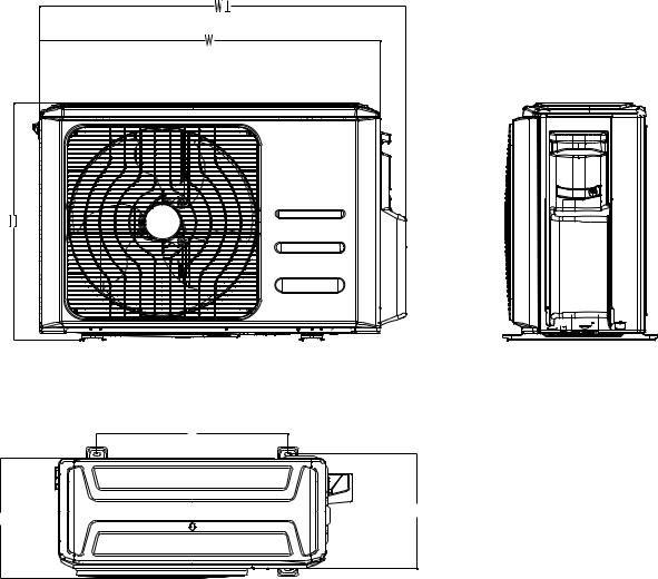
3.2 Outdoor Unit
A |
D |
B |
|
Note: The above drawing is only for reference. The appearance of your units may be different.
Model |
|
W |
D |
H |
W1 |
A |
B |
|
YN009GMFI22RPD |
mm |
770 |
300 |
555 |
840 |
487 |
298 |
|
inch |
30.3 |
11.8 |
21.9 |
33.1 |
19.2 |
11.7 |
||
|
||||||||
|
mm |
800 |
333 |
554 |
870 |
514 |
340 |
|
YN012GMFI22RPD |
|
|
|
|
|
|
|
|
inch |
31.5 |
13.1 |
21.8 |
34.3 |
20.2 |
13.4 |
||
|
||||||||
|
|
|
|
|
|
|
|
|
|
mm |
845 |
363 |
702 |
914 |
540 |
350 |
|
YN018GMFI22RPD |
|
|
|
|
|
|
|
|
inch |
33.3 |
14.3 |
27.6 |
36.0 |
21.3 |
13.8 |
||
|
||||||||
|
|
|
|
|
|
|
|
|
YN024GMFI22RPD |
mm |
946 |
410 |
810 |
1030 |
673 |
403 |
|
YN036GMFI17RUD |
inch |
37.2 |
16.1 |
31.9 |
40.6 |
26.5 |
15.9 |
|
YN048GMFI17RUD |
mm |
952 |
415 |
1333 |
1045 |
634 |
404 |
|
|
|
|
|
|
|
|
||
inch |
37.5 |
16.3 |
52.5 |
41.1 |
25.0 |
15.9 |
||
|
||||||||
|
|
|
|
|
|
|
|
23
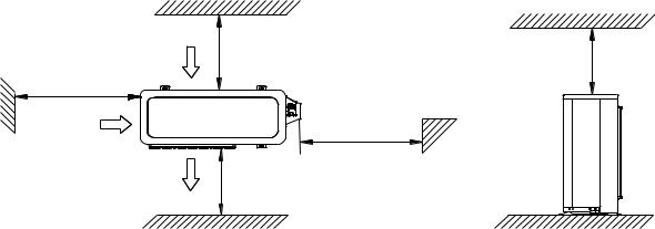
4. Service Space
4.1 Indoor Unit
Duct Units
Ensure enough space required for installation and maintenance.
|
200mm(7.87in) or more |
300mm(11.81in) or more |
||||
|
||||||
|
|
|
|
|
|
|
|
|
|
|
|
|
|
|
|
|
|
|
|
|
|
|
|
|
|
|
|
|
|
|
|
|
|
|
|
|
|
|
|
|
|
|
|
|
|
|
|
|
|
|
|
|
|
|
|
600mmx600mm/23.62inx23.62in Check orifice
All the indoor units reserve the hole to connect the fresh air pipe. The hole size as following
Cassette Units
Unit: mm
24

Console Unit
Ceiling-floor Units
25
4.2 Outdoor Unit
(Wall or obstacle)
Air inlet |
More than 30cm(11.81in) |
More than 30cm |
|
(11.81in) |
Maintain channel |
|
Air inlet |
|
More than 60cm |
|
(23.62in) |
|
|
|
|
|
Air outlet |
More than 200cm(78.74in) |
|
|
More than 60cm (23.62in)
26
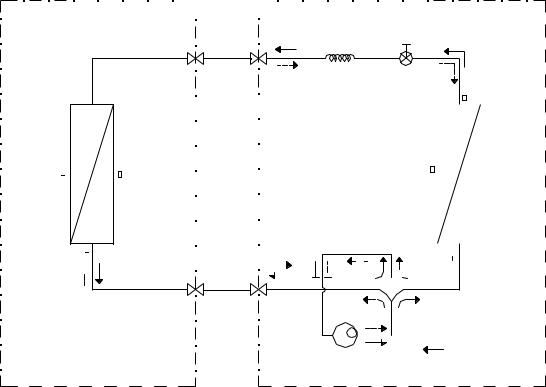
5. Refrigerant Cycle Diagram
INDOOR |
|
|
|
|
|
|
|
|
OUTDOOR |
|||||||||||||||
|
|
|
|
|
|
|
|
|
|
|
|
|
|
|
|
|
|
|
|
|
|
|
|
|
|
|
|
|
|
|
|
|
|
|
|
|
|
|
|
|
|
|
|
|
|
|
|
|
|
|
|
|
|
|
|
|
|
|
|
|
|
|
|
|
|
|
|
|
|
|
|
|
|
|
HEAT EXCHANGE (EVAPORATOR)
T2 Evaporator 
 temp. sensor middle
T2B Evaporator
 temp. sensor outlet
|
Electronic |
LIQUID SIDE |
CAPILIARY TUBE expansion valve |
2-WAY VALVE |
T3 Condenser |
|
temp. sensor |
|
|
|
|
|
|
|
|
|
T4 Ambient |
|
|
|
HEAT |
||
|
|
|
|
|
|
|
|
|
|
|
|
||||
|
|
|
|
|
|
|
|
|
|
|
|
||||
|
|
|
|
|
|
|
|
|
|
|
|
||||
|
|
|
|
|
|
|
|
|
|
|
|
||||
|
|
|
|
|
|
|
|
|
|
|
|
||||
T1 Room temp. |
|
|
|
|
|
|
|
||||||||
|
|
|
|
|
|
|
|
|
|
EXCHANGE |
|||||
sensor |
|
|
|
|
|
|
|
|
temp. sensor |
|
|
|
(CONDENSER) |
||
|
|
|
|
|
|
|
|
|
|
|
|
|
|
|
|
|
|
|
|
|
|
|
|
|
|
|
|
|
|
|
|
|
|
|
|
|
|
|
|
|
|
|
|
|
|
|
|
|
|
|
|
|
|
|
|
|
|
|
|
|
|
|
|
|
|
|
|
|
|
|
|
|
|
|
|
|
|
|
|
|
|
|
|
|
|
|
|
|
|
|
|
|
|
|
|
|
|
|
|
|
|
|
|
|
|
|
|
|
|
|
|
GAS SIDE 


 4-WAY VALVE
3-WAY VALVE
 T5 Discharge

 temp. sensor
Compressor |
COOLING |
|


 HEATING
27
 Loading...