


5.1ch Surround System
HTP-GS1
SX-X360
S-X360
Audio Multi-channel Receiver Subwoofer
Speaker System
Discover the benefits of registering your product online at www.pioneer.co.uk
(www.pioneer-eur.com).
Operating Instructions
IMPORTANT
CAUTION
RISK OF ELECTRIC SHOCK
DO NOT OPEN
The lightning flash with arrowhead symbol, within an equilateral triangle, is intended to alert the user to the presence of uninsulated "dangerous voltage" within the product's enclosure that may be of sufficient magnitude to constitute a risk of electric shock to persons.
CAUTION:
TO PREVENT THE RISK OF ELECTRIC SHOCK, DO NOT REMOVE COVER (OR BACK). NO USER-SERVICEABLE PARTS INSIDE. REFER SERVICING TO QUALIFIED SERVICE PERSONNEL.
The exclamation point within an equilateral triangle is intended to alert the user to the presence of important operating and maintenance (servicing) instructions in the literature accompanying the appliance.
D3-4-2-1-1_En-A
WARNING
This equipment is not waterproof. To prevent a fire or shock hazard, do not place any container filed with liquid near this equipment (such as a vase or flower pot) or expose it to dripping, splashing, rain or moisture.
WARNING
Before plugging in for the first time, read the following section carefully.
The voltage of the available power supply differs according to country or region. Be sure that the power supply voltage of the area where this unit will be used meets the required voltage (e.g., 230V or 120V) written on the rear panel.
WARNING
To prevent a fire hazard, do not place any naked flame sources (such as a lighted candle) on the equipment.
Operating Environment
Operating environment temperature and humidity: +5 ºC to +35 ºC (+41 ºF to +95 ºF); less than 85 %RH (cooling vents not blocked)
Do not install this unit in a poorly ventilated area, or in locations exposed to high humidity or direct sunlight (or strong artificial light)
This product is for general household purposes. Any failure due to use for other than household purposes (such as long-term use for business purposes in a restaurant or use in a car or ship) and which requires repair will be charged for even during the warranty period.
This product complies with the Low Voltage Directive (73/23/EEC, amended by 93/68/EEC), EMC Directives (89/336/EEC, amended by 92/31/EEC and 93/68/EEC).
If the AC plug of this unit does not match the AC outlet you want to use, the plug must be removed and appropriate one fitted. Replacement and mounting of an AC plug on the power supply cord of this unit should be performed only by qualified service personnel. If connected to an AC outlet, the cut-off plug can cause severe electrical shock. Make sure it is properly disposed of after removal.
The equipment should be disconnected by removing the mains plug from the wall socket when left unused for a long period of time (for example, when on vacation).
CAUTION
The STANDBY/ON switch on this unit will not completely shut off all power from the AC outlet. Since the power cord serves as the main disconnect device for the unit, you will need to unplug it from the AC outlet to shut down all power. Therefore, make sure the unit has been installed so that the power cord can be easily unplugged from the AC outlet in case of an accident. To avoid fire hazard, the power cord should also be unplugged from the AC outlet when left unused for a long period of time (for example, when on vacation).
POWER-CORD CAUTION
Handle the power cord by the plug. Do not pull out the plug by tugging the cord and never touch the power cord when your hands are wet as this could cause a short circuit or electric shock. Do not place the unit, a piece of furniture, etc., on the power cord, or pinch the cord. Never make a knot in the cord or tie it with other cords. The power cords should be routed such that they are not likely to be stepped on. A damaged power cord can cause a fire or give you an electrical shock. Check the power cord once in a while. When you find it damaged, ask your nearest PIONEER authorized service center or your dealer for a replacement.
Replacement and mounting of an AC plug on the power supply cord of this unit should be performed only by qualified service personnel.
IMPORTANT: THE MOULDED PLUG
This appliance is supplied with a moulded three pin mains plug for your safety and convenience. A 5 amp fuse is fitted in this plug. Should the fuse need to be replaced, please ensure that the replacement fuse has a rating of 5 amps and that it is approved by ASTA or BSI to BS1362.
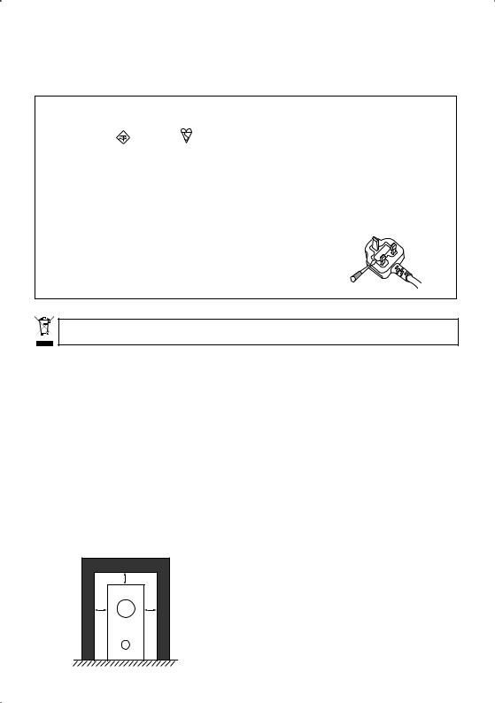
Check for the ASTA mark |
or the BSI mark |
on the body of the fuse. |
If the plug contains a removable fuse cover, you must ensure that it is refitted when the fuse is replaced. If you lose the fuse cover the plug must not be used until a replacement cover is obtained. A replacement fuse cover can be obtained from your local dealer.
If the fitted moulded plug is unsuitable for your socket outlet, then the fuse shall be removed and the plug cut off and disposed of safely. There is a danger of severe electrical shock if the cut off plug is inserted into any 13 amp socket.
If a new plug is to be fitted, please observe the wiring code as shown below. If in any doubt, please consult a qualified electrician.
IMPORTANT: The wires in this mains lead are coloured in accordance with the following code: Blue : Neutral Brown : Live
As the colours of the wires in the mains lead of this appliance may not correspond with the coloured markings identifying the terminals in your plug, proceed as follows ;
The wire which is coloured BLUE must be connected to the terminal which is marked with the letter N or coloured BLACK.
The wire which is coloured BROWN must be connected to the terminal which is marked with the letter L or coloured RED.
How to replace the fuse: Open the fuse compartment with a screwdriver and replace the fuse.
D3-4-2-1-2-2_B_En
If you want to dispose this product, do not mix it with general household waste. There is a separate collection system for used electronic products in accordance with legislation that requires proper treatment, recovery and recycling.
Private households in the 25 member states of the EU, in Switzerland and Norway may return their used electronic products free of charge to designated collection facilities or to a retailer (if you purchase a similar new one).
For countries not mentioned above, please contact your local authorities for the correct method of disposal.
By doing so you will ensure that your disposed product undergoes the necessary treatment, recovery and recycling and thus prevent potential negative effects on the environment and human health.
VENTILATION CAUTION
When installing this unit, make sure to leave space around the unit for ventilation to improve heat radiation (at least 5 cm at top, 5 cm at rear, and 5 cm at each side).
WARNING
Slots and openings in the cabinet are provided for ventilation to ensure reliable operation of the product, and to protect it from overheating. To prevent fire hazard, the openings should never be blocked or covered with items (such as newspapers, table-cloths, curtains) or by operating the equipment on thick carpet or a bed.
|
5 cm |
5 cm |
5 cm |
Receiver subwoofer

What’s in the box
Please confirm that the following items are all supplied.
Receiver subwoofer (SX-X360) box:
•Remote control (page 14)
•AA/LR6 alkaline batteries (page 15)
•Display unit (page 13)
•Stand for display x 2 (page 10)
•Power cord (page 11)
•AM loop antenna (page 9)
•FM wire antenna (page 9)
•Display cable (page 9)
•Optical cable (page 9)
•Microphone (for Auto MCACC setup) (page 16)
•These operating instructions
•Warranty card
Speakers (S-X360) box:
•Speakers (front x 2, surround x 2, center x 1) (page 6)
•Non-skid pads (small) x 12 (page 6)
•Non-skid pads (large) x 4 (page 6)
•Mounting Brackets x 4 (page 8)
•Screws (for mounting brackets) x 4 (page 8)
•Speaker cables x 5 (page 10)

Contents
Thank you for buying this Pioneer product.
Please read through these operating instructions so that you will know how to operate your model properly. After you have finished reading the instructions, put them in a safe place for future reference.
Contents
Whatís in the box. . . . . . . . . . . . . . . . . . . . . . . . . . . . . 4
01 Speaker Setup Guide
Safety precautions when setting up . . . . . . . . . . . . . . . 6
Home theater sound setup . . . . . . . . . . . . . . . . . . . . . 6 Standard surround setup . . . . . . . . . . . . . . . . . . . . . 6 Front surround setup. . . . . . . . . . . . . . . . . . . . . . . . . 7
Wall mounting the front and surround speaker
system . . . . . . . . . . . . . . . . . . . . . . . . . . . . . . . . . . . . . 8 Attaching the brackets . . . . . . . . . . . . . . . . . . . . . . . 8 Before mounting . . . . . . . . . . . . . . . . . . . . . . . . . . . . 8
Additional notes on speaker placement . . . . . . . . . . . . 8
02 Connecting up
Basic connections . . . . . . . . . . . . . . . . . . . . . . . . . . . . 9
Using this system for TV audio. . . . . . . . . . . . . . . . . . 12
06 Listening to the radio
Listening to the radio . . . . . . . . . . . . . . . . . . . . . . . . . 22
Improving poor FM reception . . . . . . . . . . . . . . . . . 22
Improving poor AM sound. . . . . . . . . . . . . . . . . . . . 22 Memorizing stations . . . . . . . . . . . . . . . . . . . . . . . . 22
Listening to station presets . . . . . . . . . . . . . . . . . . . 22
Using RDS. . . . . . . . . . . . . . . . . . . . . . . . . . . . . . . . . 23
Displaying RDS information . . . . . . . . . . . . . . . . . . 23 Searching for RDS programs . . . . . . . . . . . . . . . . . 23
07 Surround sound settings
Using the Setup menu. . . . . . . . . . . . . . . . . . . . . . . . 24 Channel level setting . . . . . . . . . . . . . . . . . . . . . . . . 24 Speaker distance setting . . . . . . . . . . . . . . . . . . . . . 24 Dynamic Range Control . . . . . . . . . . . . . . . . . . . . . 24 Dual mono setting. . . . . . . . . . . . . . . . . . . . . . . . . . 25
Adjusting the channel levels using the test tone . . . . 25
03 Controls and displays
Display unit . . . . . . . . . . . . . . . . . . . . . . . . . . . . . . . . 13 Display . . . . . . . . . . . . . . . . . . . . . . . . . . . . . . . . . . 13 Remote control . . . . . . . . . . . . . . . . . . . . . . . . . . . . . 14 Using the remote control . . . . . . . . . . . . . . . . . . . . . . 15
Putting the batteries in the remote control . . . . . . . . 15
04 Getting started
System demo setting . . . . . . . . . . . . . . . . . . . . . . . . . 16
Using the Auto MCACC setup for optimal surround sound . . . . . . . . . . . . . . . . . . . . . . . . . . . . . . . . . . . . 16
08 Other connections
Connecting auxiliary components . . . . . . . . . . . . . . . 26 Connecting an analog audio component. . . . . . . . . 26 Listening to an external audio source . . . . . . . . . . . . 26 Connecting external antennas . . . . . . . . . . . . . . . . . . 26 Using this unit with a Pioneer plasma display . . . . . . 27 SR+ Setup for Pioneer plasma displays . . . . . . . . . 27
Using the SR+ mode with a Pioneer plasma
display. . . . . . . . . . . . . . . . . . . . . . . . . . . . . . . . . . . 28 About the control out jack . . . . . . . . . . . . . . . . . . . . . 28
05 Listening to your system
Auto listening mode . . . . . . . . . . . . . . . . . . . . . . . . . 18
Listening in surround sound . . . . . . . . . . . . . . . . . . . 18 Dolby Pro Logic II Music settings . . . . . . . . . . . . . . 18
Using Front Surround . . . . . . . . . . . . . . . . . . . . . . . . 19 Using Advanced Surround. . . . . . . . . . . . . . . . . . . . . 19 Listening in stereo . . . . . . . . . . . . . . . . . . . . . . . . . . . 19 Using the Sound Retriever . . . . . . . . . . . . . . . . . . . . . 20
Listening with Acoustic Calibration EQ . . . . . . . . . . . 20
Enhancing dialogue. . . . . . . . . . . . . . . . . . . . . . . . . . 20
Using Quiet and Midnight listening modes . . . . . . . . 20 Adjusting the bass and treble . . . . . . . . . . . . . . . . . . 20
Boosting the bass level . . . . . . . . . . . . . . . . . . . . . . . 21
09 Additional information
Setting the sleep timer. . . . . . . . . . . . . . . . . . . . . . . . 29 Dimming the display . . . . . . . . . . . . . . . . . . . . . . . . . 29 DTS CD setting . . . . . . . . . . . . . . . . . . . . . . . . . . . . . 29 Resetting the system . . . . . . . . . . . . . . . . . . . . . . . . . 29
Installation and maintenance . . . . . . . . . . . . . . . . . . 29
Hints on installation . . . . . . . . . . . . . . . . . . . . . . . . 29 Glossary. . . . . . . . . . . . . . . . . . . . . . . . . . . . . . . . . . . 30
Setting up the remote to control your TV . . . . . . . . . . 30 Using the TV remote control buttons . . . . . . . . . . . . 31
Preset code list . . . . . . . . . . . . . . . . . . . . . . . . . . . . 31 Troubleshooting. . . . . . . . . . . . . . . . . . . . . . . . . . . . . 32 General . . . . . . . . . . . . . . . . . . . . . . . . . . . . . . . . . . 32 Tuner. . . . . . . . . . . . . . . . . . . . . . . . . . . . . . . . . . . . 33 Error Messages . . . . . . . . . . . . . . . . . . . . . . . . . . . . 33 Specifications . . . . . . . . . . . . . . . . . . . . . . . . . . . . . . 34
English
5
En
01 Speaker Setup Guide
Chapter 1
Speaker Setup Guide
Safety precautions when setting up
When assembling the speakers, lay them down flat on their side to avoid accidents or injury. Make sure to use a stable surface when assembling, setting up, and placing the speakers.
Home theater sound setup
Depending on the size and characteristics of your room, you can place your speakers in one of two ways using this system:
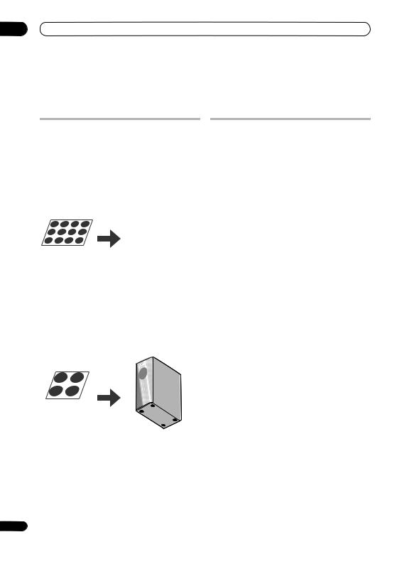
• Attach the smaller non-skid pads to the base of each of the front speakers and the center speaker. The four large non-skid pads are for the receiver subwoofer (as shown).
Use the supplied adhesive to attach 4 pads to the base (flat surface) of each speaker.
Non-skid pads (small) x 12
Front speakers |
Center speaker |
|
Non-skid pads (large) x 4
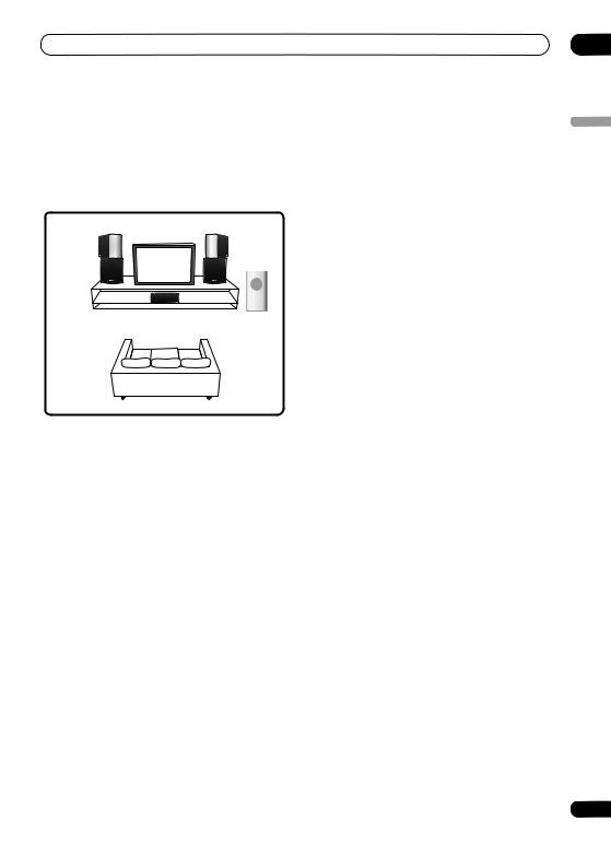
Standard surround setup
This is a standard multichannel surround sound speaker setup for optimal 5.1 channel home theater sound. Use this setup together with Auto listening mode on page 18 or other listening mode.
Front |
Front |
left |
right |
|
Center |
|
Receiver subwoofer |
Surround |
Surround |
left |
right |
Listening position
•Connect the speaker system.
Refer to Connecting up to connect the speakers properly. After connecting everything, place the speakers as shown in the diagram (above) for optimal surround sound.
After placing the speakers, run the Auto MCACC setup (page 16) to complete your surround sound setup.
Receiver subwoofer
6
En
Speaker Setup Guide |
01 |
Front surround setup
This setup is ideal when rear surround speaker placement isn't possible or you want to avoid running long speaker cables in your listening area. Use this setup together with the Front Surround modes in page 19 to take advantage of wall and ceiling reflections for a very realistic surround effect.
Surround left |
Surround right |
Front left |
Front right |
|
CenterC |
|
Receiver |
|
subwoofer |
Listening position
1Connect the speaker system.
Refer to Connecting up to connect the speakers properly. After connecting everything, place the speakers as shown in the diagram (above) for optimal surround sound.
The base of each surround speaker fits into the circular groove on the top of the front speakers as shown.
3 Turn the surround speakers towards the closest wall, lining the arrows up for optimal Front Surround.
Turn each surround speaker so that the arrow at the base is lined up with the FRONT SURROUND arrow on the front speaker. This is only necessary with the
FRTMOVIE or FRTMUSIC modes. With EXTPOWER
(Extra Power), line up the arrow with the EXTRA POWER arrow (the surround speakers should be in the same direction as the front speakers.). See Using Front Surround on page 19 for more on this.
FRTMOVIE / FRTMUSIC |
EXTPOWER |
English
2Secure the speaker wire.
After testing for the slack necessary to turn the speaker (see the following step), use the groove provided to secure the speaker wire as shown. Leave 5 cm of slack from the speaker terminals so the upper (surround) speaker can turn freely.
After placing the speakers, run the Auto MCACC setup (page 16) to complete your surround sound setup.
 Caution
To prevent accidents, make sure the surround speaker is placed securely on top of the front speaker.
Please don't attach the speakers to the wall or speaker stands for Front surround setup.
7
En
01 Speaker Setup Guide
Wall mounting the front and surround speaker system
The front and surround speakers have holes for wall mounting. However, if you are using the Front Surround setup described on the previous page, do not wall mount the surround speakers.
 Caution
If you are unsure of the qualities and strength of the wall, consult a professional for advice.
Pioneer is not responsible for any accidents or damage that result from improper installation.
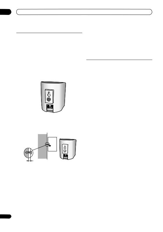
Attaching the brackets
Make sure to tighten the supplied screw as securely as possible when attaching the bracket to the back of the speaker.
Please do not attach the brackets to the center speaker.
Bracket screw (supplied)
 5 mm 10 mm
Mounting screw (not supplied)
5 mm to 7 mm
Before mounting
Remember that the speaker system is heavy and that its weight could cause the wood screws to work loose, or the wall material to fail to support it, resulting in the speaker falling. Make sure that the wall on which you intend to mount the speakers is strong enough to support them. Do not mount on plywood or soft surface walls.
Mounting screws are not supplied. Use screws that are suitable for the wall material and that will support the weight of the speaker.
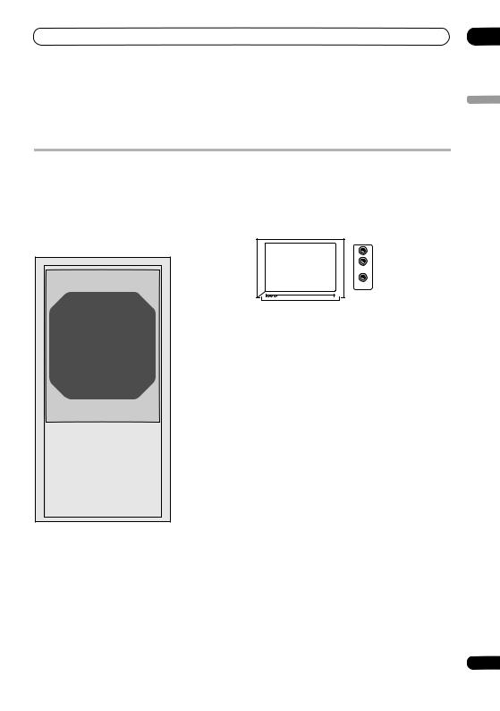
Additional notes on speaker placement
Install the main front left and right speakers at an equal distance from the TV.
For optimum effect, install the surround speakers slightly above ear level.
Install the center speaker above or below the TV so that the sound of the center channel is localized at the TV screen.
When installing the center speaker on top of the TV, be sure to secure it with suitable means. Otherwise, the speaker may fall from the TV due to external shocks such as earthquakes, endangering those nearby or damaging the speaker.
This front, center and surround speakers supplied with this system are magnetically shielded. However, depending on the installation location, color distortion may occur if the speaker is installed extremely close to the screen of a television set. If this happens, turn the power switch of the television set OFF, and turn it ON after 15 to 30 minutes. If the problem persists, place the speaker system away from the television set.
The receiver subwoofer is not magnetically shielded and so should not be placed near a TV or monitor. Magnetic storage media (such as floppy discs and tape or video cassettes) should also not be kept close to the receiver subwoofer.
 Caution
Do not attach the center speaker or the receiver subwoofer to the wall or ceiling; they could cause injury if they fell.
Do not connect the supplied speakers with any other amplifier. This may result in malfunction or fire.
Do not connect any speakers other than those supplied to this system.
For safety, make sure that there is no exposed bare speaker wire outside of the speaker terminals.
8
En
Connecting up
Chapter 2
Connecting up
Basic connections
 Important
When connecting this system or changing connections, be sure to switch power off and disconnect the power cord from the wall socket.
After completing all connections, connect the power cord to the wall socket.
|
|
Audio/video output |
Receiver subwoofer |
|
(red, white, yellow plugs) |
FM antenna |
|
|
|
|
|
|
|
AUDIO IN |
|
|
VIDEO IN |
|
AM loop antenna |
|
|
3 |
|
|
4 |
Output for component video |
|
(red, blue, green plugs) |
|
|
|
|
|
Display unit |
a |
|
|
HD AV cable |
ANTENNA |
|
|
MCACC CONTROL IN |
LOOP ANTENNA |
Xbox360 |
UNBAL 75Ω |
||
SETUP MIC |
|
|
FM |
AM |
|
AUDIO INPUT |
|
|
|
CONTROL |
|
SPEAKERS |
|
|
DIGITAL |
|
|
||
SYSTEM CONNECTOR |
|
|
DVD/DVR |
XBOX 360 |
DIGITAL |
ANALOG |
||||
OUT |
SUB WOOFER |
R SURROUND |
L |
|||||||
|
(COAXIAL) |
(OPTICAL) |
(OPTICAL) |
|
||||||
|
|
|
|
|
|
|
|
|
L |
|
USE ONLY WITH |
|
|
|
|
|
|
|
|
R |
|
|
|
|
|
|
|
|
|
|
||
DISPLAY UNIT |
|
CENTER |
R |
FRONT |
L |
|
|
|
|
|
|
|
|
|
|
|
|||||
AC IN
Display cable
2 |
b Optical cable |
1 |
|
|
02
English
9
En

02 Connecting up
1 Connect the Xbox 360 to your TV and the receiver subwoofer.
a.Connect the Xbox 360 Component HD AV Cable (this is supplied with your Xbox 360) to the AV port on the rear of the Xbox 360 console.
Plug the yellow video plug into a video input on your TV/monitor. Plug the red/white audio plugs into the audio inputs on your TV/monitor.
If your TV has a component video input, you can use this instead of the yellow (composite) video connection. See your Xbox 360 user manual for more information.
b.Plug an optical cable (supplied) into the XBOX 360 (OPTICAL) jack on the rear of the receiver subwoofer, then plug the other end into the digital audio output on the HD AV Cable.
2 Connect the display unit to the receiver subwoofer.
Plug the L-shaped end of the display cable into the connector on the rear of the display unit, then plug the other end of the display cable into SYSTEM CONNECTOR jack on the receiver subwoofer.
To attach the stands to the display unit, slip the two spurs on the top of each stand into the corresponding holes on the rear of the display unit, then snap the stand into place by pushing the catches on the stand base into the bottom set of holes (as shown).
3Assemble the AM loop antenna.
a |
b |
c |
a.Bend the stand in the direction indicated by the arrow.
b.Clip the loop onto the stand.
c.If you want to fix to a wall or other surface, perform step b after first securing the stand with screws.
It is recommended that you determine the reception strength before securing the stand with the screws.
4Connect the AM and FM antennas1.
a.Connect one wire of the AM loop antenna to each AM antenna terminal2.
For each terminal, press down on the tab to open; insert the wire, then release to secure.
1


 2
2
b.Push the FM antenna3 plug onto the center pin of the FM antenna socket.
5Connect each speaker.
Each speaker cable has a color-coded connector at one end and two wires at the other end.
Color-coded wire
(Connect to speaker)
Color-coded connector (Connect to rear panel)
Twist and pull off the protective shields on each wire.
Connect the wires to the speaker. Match the colored wired with the color-coded label (model label), then insert the colored wire into the red (+) side and the other wire into the black (–) side.
 Note
Note
1 Keep antenna cables away from other cables, the display unit, receiver subwoofer and DVD recorder.
If reception with the supplied antenna is poor, see Improving poor FM reception and Improving poor AM sound on page 22 or Connecting external antennas on page 26.
2 Donít let it come into contact with metal objects and avoid placing near computers, television sets or other electrical appliances.
The signal earth ( ) is designed to reduce noise that occurs when an antenna is connected. It is not an electrical safety earth.
If radio reception is poor, you may be able improve it by re-inserting each antenna wire into the opposite terminal.
For best reception, do not untwist the AM loop antenna wires or wrap them around the loop antenna.
3 To ensure optimum reception, make sure the FM antenna is fully extended and not coiled or hanging at the rear of the unit.
10
En
Connecting up |
02 |
•Connect the other end to the color-coded speaker terminals on the rear of the receiver subwoofer. Make sure to insert completely.
The small lug at the wire-end of the speaker plug should face up or down depending on whether it’s being plugged into one of the upper or lower speaker terminals. Please make sure to connect correctly.
Upper terminal |
Lower terminal |
6Connect the subwoofer cable.
•Just below the subwoofer speaker, to the left of center, you should see the subwoofer connecting cable. Plug this into the SUBWOOFER SPEAKER terminal.
Receiver subwoofer
|
|
|
|
|
|
|
ANTENNA |
|
|
|
|
|
6 |
|
MCACC |
CONTROL IN |
|
|
|
|
|
||
|
|
SETUP MIC |
|
FM |
|
|
|
AM |
|||
|
|
|
|
|
|
|
|
|
|||
|
|
R |
|
|
L |
UNBAL 75Ω |
|
|
LOOP ANTENNA |
||
|
|
|
|
|
5 |
AUDIO |
INPUT |
|
|||
|
CONTROL |
|
SPEAKERS |
|
|
DIGITAL |
|
|
|
||
SYSTEM CONNECTOR |
|
|
DVD/DVR |
XBOX 360 |
|
DIGITAL |
ANALOG |
||||
OUT |
SUB WOOFER |
|
SURROUND |
|
(COAXIAL) |
(OPTICAL) |
(OPTICAL) |
|
|||
|
|
|
|
||||||||
|
|
|
|
|
|
|
|
|
|
|
L |
USE ONLY WITH |
|
|
|
|
|
|
|
|
|
|
R |
|
|
|
|
|
|
|
|
|
|
|
|
DISPLAY UNIT |
|
CENTER |
R |
|
FRONT |
L |
|
|
|
|
|
|
|
|
|
|
|
|
|
||||
|
AC IN |
|
|
|
|
|
|
|
|
|
|
7 
To AC outlet
 Caution
•These speaker terminals carry HAZARDOUS LIVE voltage. To prevent the risk of electric shock when connecting or disconnecting the speaker cables, disconnect the power cord before touching any uninsulated parts.
•Do not connect any speakers other than those supplied to this system.
•Do not connect the supplied speakers to any amplifier other than the one supplied with this system. Connection to any other amplifier may result in malfunction or fire.
7 Connect the power cords.1
Connect the power cords to AC inlets on the receiver subwoofer and Xbox 360. Connect the power cords to a wall socket.
Surround right |
Surround left |
(Gray) |
(Blue) |
Listening position
Front right |
Center (Green) |
Front left |
|
||
(Red) |
|
(White) |
English
 Note
Note
1 • Do not use any power cord other than the one supplied with this system.
• Do not use the supplied power cord for any purpose other than connecting to this system.
11
En
 Loading...