


SX-9000
INSTALLAT
ION.
OPERATION
AND
Including PARTS
TROUBLE
SERVICE
SHOOTING
LIST, CIRCUIT
MANUAL
DIAGRAMS,
MOUNTING TEMPLATE.
AND
rJIONEEIiI'
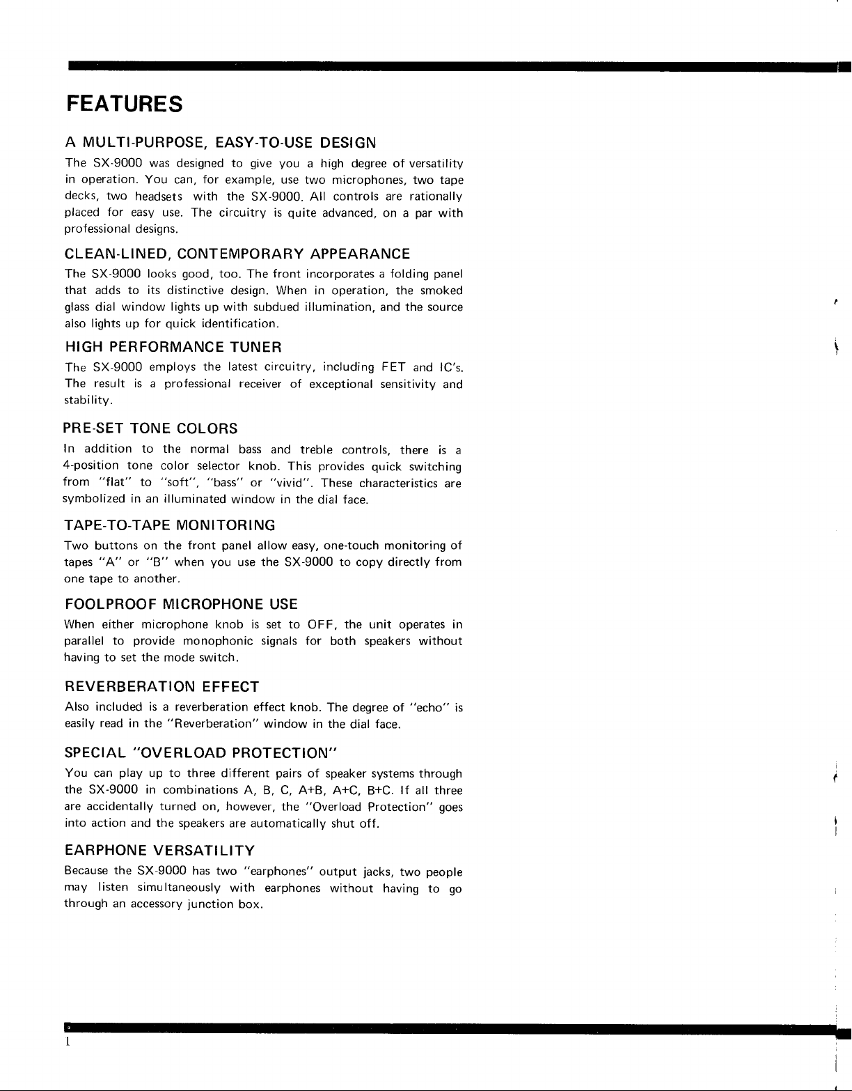
FEATURES
A MULTI-PURPOSE,
The SX-9000 was
in operation.
decks,
placed
professional
You can, for example,
two
headsets with
for
easy use.
designs.
EASY-TO.USE
designed to
The circuitry is
give you
the SX 9000. All controls
DESIGN
a high degree of versatility
use two microphones, two tape
are rationallv
qrlite
advanced, on a
CLEAN-LINED, CONTEMPORARY APPEARANCE
good,
The SX-9000
that adds to its
glass
dial window lights up with subdued illumination. and the source
also lights up for
HIGH
SX-9000
The
resu
The
stab i I ity.
PRE-SET
In addition
4-position
"flat"
from
svmbolized
TAPE-TO-TAPE
Two buttons
"A"
tapes
one tape to another.
looks
distinctive design. When in operation, the smoked
quick
PERFORMANCE
employs
lt is a
professional
TONE COLORS
to the normal
tone
color selector
"soft",
to
in an illuminated
MON ITOR
on the front
"8"
or
when
too.
identification.
The
front
incorporates
TUNER
latest
the
"bass"
circuitry, including FET
receiver
bass and
window in the
knob.
"vivid".
or
of
exceptional sensitivity
treble
provides
This
These cttaracteristics
dial face.
controls, there
I NG
panel
allow
you
use the SX 9000 to copy directly
easy,
one-touch
a folding
quick
switching
monitoring
par
with
panel
and lC's.
and
is a
are
of
from
FOOLPROOF MICROPHONE
When either microphone knob is set to
parallel
having
REVERBERATION
Also included is a reverberation
easily
SPECIAL
You can
the SX-9000 in
are accidentally turned
into action and the speakers
EARPHONE
Because the
may I isten
through
provide
to
to set the mode switch.
monophonic signals
EFFECT
read
play
an accessory
"Reverberation"
in the
"OVERLOAD
up to three different
combinations
on,
VERSATILITY
SX-9000 has two
simu ltaneously
junction
however,
USE
effect knob.
window
PROTECTION''
pairs
A, B, C, A+8,
the
are automatically
"earphones"
with earphones
box.
the unit operates in
OFF,
for both
in the
of speaker systems through
"Overload
output
speakers
The degree of
face"
dial
A+C, B+C.
Protection"
shut off.
jacks,
without
having to go
without
"echo"
lf
all three
two
goes
people
is
I
TJTONEER
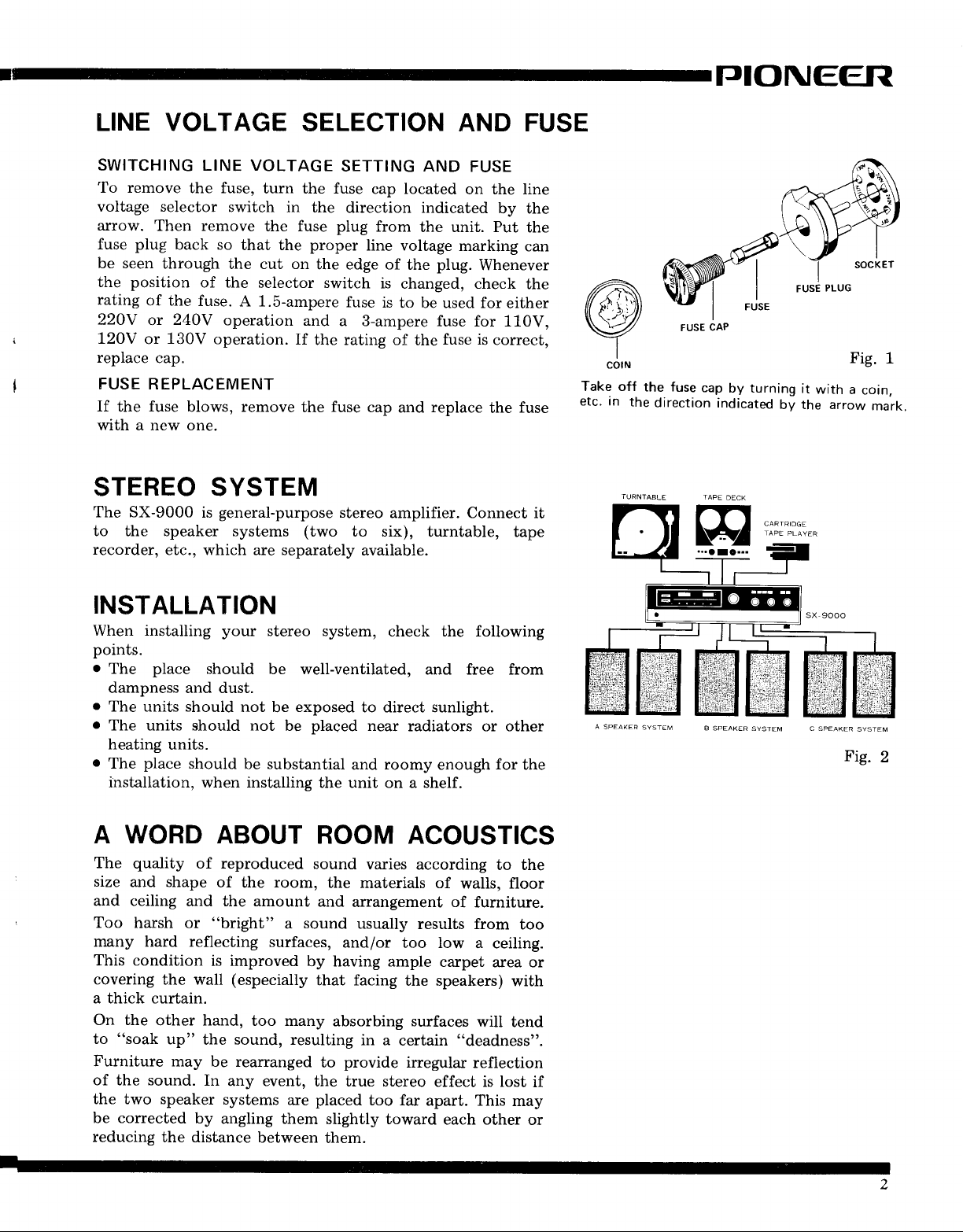
LINE VOLTAGE
SWITCHING
To remove
voltage selector
arrow.
fuse
Then remove
plug
be seen
the position
rating
22OY
120V
of the
or
or
replace
the fuse,
back so
through
fuse.
240V
130V
cap.
LINE VOLTAGE
switch
that the
the cut on
of the
A 1.5-ampere
operation
operation.
SELECTION AND FUSE
turn the fuse
in the
the fuse
proper
the edge of
selector switch
and
If
the rating of
FUSE REPLACEMENT
If
the
fuse
blows, remove
the
with a new one.
STEREO SYSTEM
The SX-9000
to the speaker systems
recorder,
etc., which are separately
general-purpose
is
(two
SETTING AND
cap located
direction indicated
plug
from
the unit. Put
line voltage
plug.
the
is
changed, check
fuse
is
to be used foreither
a S-ampere
fuse
cap
stereo
to six),
fuse for 110V,
fuse is
the
replace
and
amplifier. Connect it
turntable, tape
available.
FUSE
on the line
by the
marking
Whenever
correct,
fuse
the
the
can
the
Take off
etc. an
the fuse
the
direction
FUSE
cap
CAP
by turning
indicated
Fig.
it
with
by the arrow
a
1
coin,
mark.
INSTALLATION
When installing
points.
o
The
place
dampness and dust.
o
The units should
o
The units should not
heating
o
The
units.
place
installation, when installing
A WORD
quality
The
size
and shape
and ceiling
Too
harsh or
many hard reflecting
This condition
covering
a thick curtain.
On the
to
Furniture may
of the sound.
the two speaker
be corrected
reducing
the wall
other hand,
"soak up"
the distance
your
stereo
should
be well-ventilated,
not
exposed
be
be
should
be substantial
ABOUT ROOM ACOUSTICS
of reproduced
of
and the amount
"bright" a sound
is improved
the sound, resulting
be rearranged
In
systems
by
angling them
room,
the
surfaces,
(especially
too many
any event,
are
between
system,
check the following
and free from
to direct sunlight.
placed
near
and
radiators or other
roomy
the unit on a shelf.
sound
and
varies
the
materials of
arrangement of
usually
and/or
too low
according
results from
by having ample
that facing
the speakers)
absorbing surfaces
in a
certain "deadness".
provide
to
irregular
the true stereo
placed
too far
apart. This
slightly toward
them.
enough
for
to the
walls, floor
fumiture.
too
a ceiling.
carpet
area or
with
will tend
reflection
effect is lost
may
each other
the
if
or
A
SPEAKER
SYSTEM
B SPEAKER
SYSTEM C SPEAKER
SYSTEM
Fig.
2
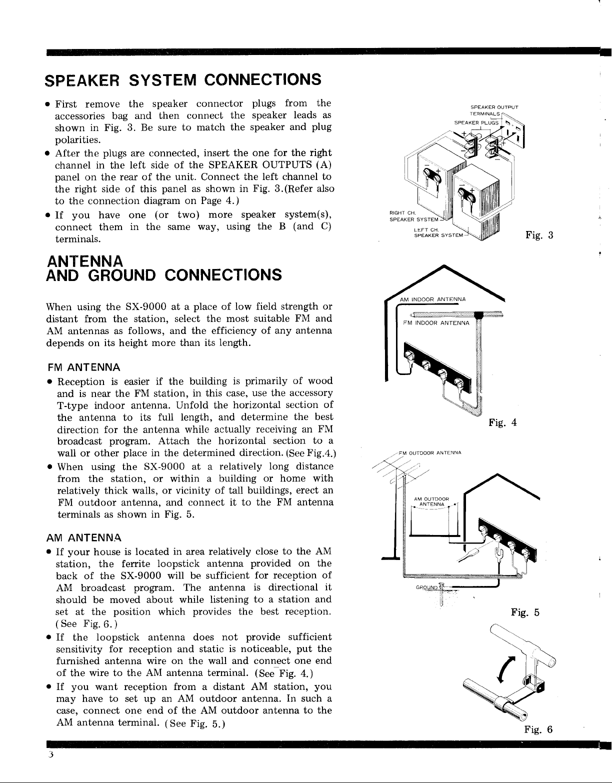
SPEAKHR
SYSTEM
CONNECTIONS
o
First remove
accessories
shown
in Fig.
bag
speaker connector
the
and then
3. Be sure
polarities.
o
After the
channel
panel
the
the connection diagram
to
.
you
If
connect
plugs
in
the
on the
connected, insert
are
side of the SPEAKER OUTPUTS
left
rear of the unit. Connect
right side of this
them
one
in the
have
terminals.
ANTENNA
AND
When using the
distant
AM antennas as
depends
FM ANTENNA
o
Reception
and
T-type
the antenna
direction
broadcast
wall or other
o
When
from the station,
relatively
FM outdoor antenna, and
terminals
GROUND
SX-9000 at a
from the station,
follows, and the efficiency
on its height
is easier
is near the
indoor
for the antenna
program. Attach the horizontal
using the
thick walls, or vicinity
as shown in Fig. 5.
more than its
FM station,
antenna.
to its
place
in the determined
SX-9000 at a relatively
or
plugs from the
speaker leads as
connect
to match the
the
speaker and
the one for the
the left channel to
panel as shown in
Fig.3.(Refer
on Page 4.)
(or
two)
same
more speaker
using
way,
the B
CONNECTIONS
place
of low field strength
select the most
length.
if the building
in this case,
Unfold the
full length, and
while actually
within
a building
of tall buildings,
connect it to
suitable FM and
of any antenna
primarily of
is
use the accessory
horizontal
determine
receiving an
section to a
direction.
long distance
or home with
the FM antenna
plug
right
(A)
also
system(s),
(and
C)
or
wood
section of
the best
FM
(See
Fig.4.)
erect an
RIGHT
CH
SPEAKER SYSTEM
LEFT CH
SPEAKER
-' FM OUTDOOR
AM
OUTDOOR
ANTENNA
SVSTEM
ANTENNA
Fig.
Fig.
3
AM ANTENNA
o
If
your
house
is located
station, the ferrite
of the SX-9000
back
AM broadcast
should be
set at the
(
Fig.
See
.
If
the
6.
loopstick antenna does
sensitivity
program. The antenna
moved about while
position
)
for reception and static is
furnished antenna wire
of the wire to the
o
you
If
may have to
want reception from a distant AM
set up
in
loopstick
will be
area
relatively
antenna
sufficient
listening to
which
provides
not
on
the wall
AM antenna terminal.
an AM
outdoor antenna. In such a
close to the AM
provided
for reception of
is directional
a station and
the best
provide sufficient
noticeable,
and connect
(SeJfig.
station,
case, connect one end of the AM outdoor antenna
AM antenna terminal.
(See
Fig.
b.)
on the
it
reception.
put
the
one
end
+.;
you
to the
Fig.
5
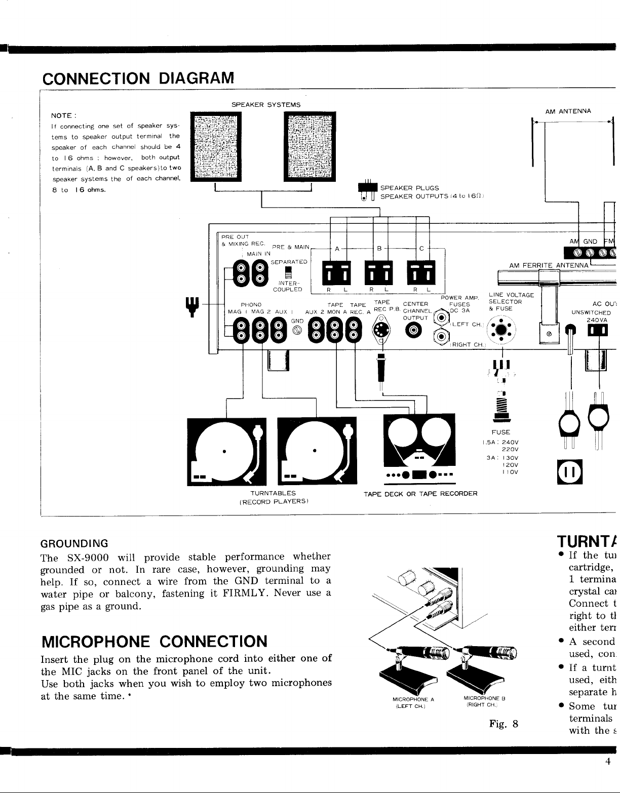
CONNECTION
NOTE:
lf connecting
speaker
to
tems
of each
speaker
| 6 ohms :
to
terminals
speaker
8
(A, B and C speakers)to
systems the
ohms.
to 16
one set
output
channel
however,
of speaker
of
DIAGRAM
sys-
should
both
the
be
outPut
two
terminal
each channel,
ANTENNA
AM
4
PRE
MIXING
&
MAG I
OUT
PHONO
REC.
pAE
t,,tntN
&
IN
MAIN
JNTfR
COUPLED
MAG
2
e*cl
TAPE TAPE
MON A
REC. A
SPEAKER PLUGS
SPEAKER
TAPE
REC
/^
P.B
OUTPUTS
CENTER
CHANNE
OUTPUT
lo)t
Y7
i4
to
| 6()
r
AM FERRITE ANTENNA
GROUNDING
provide
SX-g000
The
grounded
If so, connect
help.
water
gas
pipe or balcony,
pipe as a
MICROPHONE
Insert the
jacks
MIC
the
Use both
at the
same time.'
will
In rare case,
not.
or
ground.
plug on the
on the
jacks
when
a wire
fastening
CONNECTION
microphone
front
you
stable
from
panel
wish
(RECORD
performance
however,
GND terminal
the
FIRMLY.
it
cord
of the
to employ
TURNTABLES
PLAYERS)
whether
grounding
Never use
into either
unit.
two microphones
may
to
one
of
I
:'l
-
-4,
I
r
FUSE
240V
5A:
220V
34: |
30V
|
20v
|
oer!
TAPE DECK
OR
!
f
TAPE
...
RECORDER
10v
a
a
MICROPHONE
(LEFT
CH.)
A
#
@
TURNTI
.
If the tur
cartridge,
1
termina
crystal
Connect
right to tl
either
o
A second
used, con.
.
If a tumt
used, eith
separate h
.
Some
terminals
with the s
car
t
terr
tur
PI()NEER
-l
--1
-!
FM INDOOR
HED
ANTENNA
FM
OUTDOOR
ANTENNA
TAPE DECK
(RECORDER)
CONNECTION
.
A tape deck
record/playback
T-600
to the SX-9000.
o
The connected
terminals for tape
tape monitor terminals.
CONNECTION
Connect
(LINE
provided with
channel,
monophonic
terminal
CONNECTION
Connect the
the
Connection
above
and T-500
this unit's
IN)
the
instead.
deck
tape
paragraph.
connected to
preamplifier
feature characteristics
tape recorder
recorder connection
TAPE RECORDING
FOR
TAPE REC
terminals of
the deck.
lower for the
type, use
FOR TAPE
LINE
is done
OUT
to the
TAPE
in the
this unit
built-in.
should also have
terminals
the tape
The upper
right.
CENTER
the
PLAYBACK
or TAPE
MON terminals
same way
PIONEER's
(LINE
to the
deck.
terminal
If the tape
MONITOR
Use the
CHANNEL
(OR
as described
must have a
models
ideally
is
MONITOR)
terminals
on
suited
output
OUT)
signal input
for the left
deck
this
or
cords
is of
output
on
unit.
in the
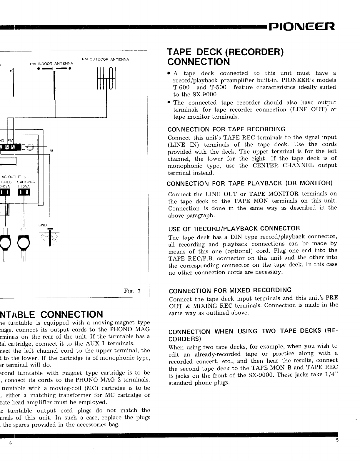
NTABLE
:re tuintable
:idge, connect
rminais
bal ca'tridge,
nect the left channel
b to the lower.
:r terminal
:cond
l, conoect
turntable
l, either
rate head
Le turntable
rinals
the spares
L
on the
turntable
of this unit.
CONNECTION
is equipped
its output cords
rear of the unit.
connect
If
the cartridge
will do.
with magnet
its cords to the
a moving-coil
with
a matching
amplifier must be employed.
output cord
In such a case,
provided in the accessories
with a
it to the
cord to the
transformer
AUX
is of
type cartridge
PHONO
(MC)
plugs
moving-magnet
PHONO
the
to
If the
turntable has
1 terminals.
upper
for
do
terminal,
monophonic
MAG 2 terminals.
cartridge
MC
cartridge
not
match
replace the
bag.
type
MAG
the
type,
is to be
is to be
or
the
plugs
USE OF
The
all
means
TAPE
the
no other
CONNECTION
Connect
OUT
same way
a
CONNECTION
CORDERS)
When
edit an
recorded
the
jacks
B
standard
RECORD/PLAYBACK
a DIN
has
deck
tape
playback
recording
of
REC/P.B.
corresponding
&
using
second
and
(optional)
one
this
connector
connector
connection
tape
the
MIXING
outlined
as
two
already-recorded
concert,
tape
the
on
phone
cords
FOR
deck
REC
WHEN
tape
etc.,
deck
front
plugs.
of the
MIXED
input
terminals.
above.
USING
decks,
and then
the
to
CONNECTOR
record/playback
type
connections
Plug
cord.
unit
this
on
the tape
on
necessary.
are
RECORDING
terminals
Connection
TWO
for example,
practice
or
tape
hear
TAPE
SX-9000.
MON B
can
one end
and the
deck.
and
TAPE
when
the
These
connector,
made
be
other
In this
unit's
this
is made
DECKS
you wish
along
results,
TAPE
and
jacks
take
by
into the
into
case
PRE
in the
(RE-
to
with
connect
REC
1/4"
a
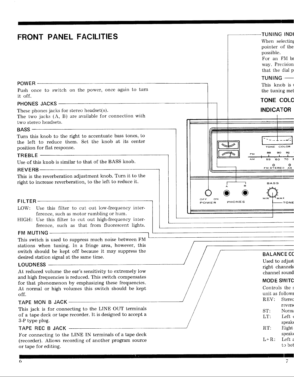
FRONT
Push once
PANEL
to switch
it off.
PHONES JACKS
These
The
phones
two
two stereo
jacks
jacks
(A,
headsets.
FACILITIES
on the
for stereo
are available
B)
power,
once
headset(s).
for connection
again
to turn
with
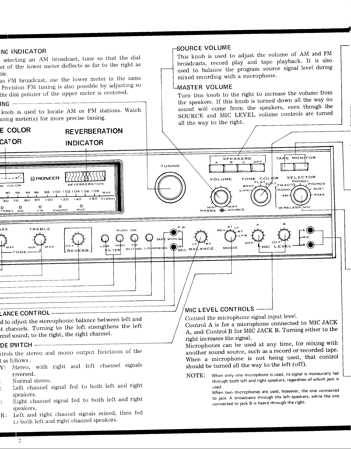
TUNING
When
pointer
I
selecti
of th
possible.
For
way.
that
FM
an
Precisi
the dial
TUNING
knob
This
is
the tunir'g
TONE
INDICATOR
Turn this
the
position for
knob to the
to
left
reduce them.
flat response.
TREBLE
Use of
this
is similar
knob
REVERB
This is the
right to
F I LTER
LOW:
HIGH:
MUTING
FM
This
stations when
switch
desired
reverberation
increase
Use this
ference,
reverberation,
filter to cut out
such
Use this filter to cut
ference, such
switch is used
to suppress much
tuning.
should be kept off
station signal at the
LOUDNESS
reduced volume the ear's
At
high frequencies
and
for that
At
off.
TAPE
This
of a tape deck
3-P type
TAPE REC B JACK
For connecting
(recorder).
or tape for editing.
phenomenon by emphasizing
normal
MON B
jack
high volumes this
or
JACK
for connecting
is
or tape
plug.
the LINE
to
Allows
recording
to
right
accentuate
Set
to that
the
of the
adjustment
the left
to
low-frequency
motor rumbling or
as
out high-frequency
as that
from fluorescent
In a fringe area,
because it
same time.
sensitivity to
is reduced. This
switch should
to the
recorder.
LINE OUT
It
is designed
IN terminals
of another
bass tones,
at its center
knob
BASS
knob.
knob. Turn
reduce it.
to
to
it to the
hum.
between FM
noise
however, this
may suppress the
extremely low
switch compensates
these frequencies.
be kept
terminals
to accept
of a tape deck
program source
COLOR
TONE
6ct
92
70
AM
OFF
PO\A/ER
ON
6
PH
e
AM
aa s
55
FM
STEREo
BALANCE
to adju
Used
chan
right
channel
MODE SIIVI
Controls
unit as fol
REV: S
a
ST:
LT:
sou
the
Right
speak
f,eft
tc
INDICATOR
NG
selecting
the
of
er
ble.
broadcast,
FM
an
Precision
dial
the
ING
is
knob
meter(s)
unir'g
COLOR
E
an
lower
FM
pointer
used
broadcast,
ANI
meter
use
tuning
the
of
locate
to
more
for
that
so
tune
to the
far
deflects
the
also
is
upper
AM
Precise
as
lower
possible
meter
or
tuning-
meter
is
FM
in
adjusting
by
ceutered'
stations'
REVERBERATION
the
right
the
dial
as
same
so
Watch
VOLUME
RCE
knob
This
broadcasts,
balance
to
used
mixed
Turn
the
sound
SOURCE
all
recording
ASTER
this
speakers.
will
waY
the
VOLUME
knob
and
used
is
record
If this
come
MIC
the
to
to
the
with
to
frorn
right.
adjust
and
play
program
microphone'
a
right
the
knob
the
LEVEL
the
tape
source
increase
to
turned
is
speakers,
volume
volume
playback'
signal
down
controls
of AM
volume
the
all
even
and
is also
It
during
level
waY
the
though
are
FM
from
no
the
turned
CATOR
COLOR
IE
s2 s1
s
:l-
;-;-;
o
\SS
TON E
INDICATOR
()
r:torueen
9A
s6
t" t""
ooo
FM
TREE}LE
1OO
PHONO
REVERB
1O21O4
12o
14o
AUX
ERATION
1O8
106
160 xlokHz
MHz
PUSH
ON
MUTING
SPEAKERS
T UNING
B.l
MON.
Lo
J
ABc
VOLUME
MIN
M A
STER
Q-
ANCE
souace
TONE
BASS.
vtvlo
COL
l.
MIC
LE
LECTOR
E
S
PHONO 1
r
.
F:,:
L"(
e.djust
to
CONTROL
the
LANCE
d
Lt channels.
sound;
nnel
SIIIITCH
DE
stereo
the
rtrols
t as
V:
r
:
:
R:
foliows
r3versed.
.
Stereo,
Normal
channel
Left
speakers.
Ii.,ight
speakers.
ar-rd
l,eft
both
tr
stereophonic
Turning
right,
the
to
aud
right
with
stereo.
sigual
channel
left
signal
right
and
the
to
the
mono
arld
fed
fed
channel
channel
right
balance
strengthens
left
channel'
right
output
left
both
to
both
to
sigr-rals
sPeakers.
between
functions
chairnel
and
left
and
left
mixed,
left
the
of
siglals
then
and
left
the
right
right
fed
LEVEL
MIC
Control
Control
A, and
right
the
is
A
Control
increases
Ul"roplrones
another
When
should
NOTE:
sound
microphone
a
turned
be
When
through
useo.
When
to
connected
CONTROLS
microphone
microphone
a
for
MIC
for
B
signal.
the
used
be
can
source'
such
is
the
all
microphone
one
only
left and
both
microphones
two
jack
A broadcasts
to
iack
signal
JACK
at any
not
way
right
through
is heard
B
input
connected
B'
record
a
as
being
the
to
used'
is
speakers'
used'
are
the
through
level'
Turning
for
time,
or
used,
(off)'
left
signal
its
regardless
however'
speakers'
left
right'
the
JACK
MIC
to
to
either
mixing
recorded
control
that
monaurally
is
which
of
connected
one
the
while
the
with
tape'
iack
the
fed
is
one
'
PIONEER
SPEAKERS
These switches
off. Push
off. Pushing the
reproduced
SPEAKER A terminals. The
their corresponding
NOTE:
you
If
the
TONE
This switch is for selecting
.
your
VIVID:
BASS: Emphasizes
FLAT:
SOFT: High
TAPE MONITOR
Depress
again
when
Turning it
This button
editing conditions.
There are
rear
correspond
jack
SELECTOR
This switch
AM:
FM MONO/WIRELESS:
FM
PHONO
PHONO
AUX 1:
Only two speaker systems can
A+8, B+C, or A+C). lf all three speaker buttons are
the same time, no sound
wish
OFF
button.
COLOR
mood
Emphasizes highs
clarity
Flat,
this button
and it
listening
(A)
and front
A, and
AUTO: For
1: For playing
2: Same
AUX 2:
MIC
JACK A,
Plug
a microphone
microphones
turn the various speaker
each button once to
A button will
from
terminals on the rear of
to shut off all
or
the music being heard.
untempered
tones relatively
shuts
on automatically
is intended
two TAPE MONITOR
to them.
button B
is for
mono
nected
For playing
terminals.
Same
off. During record
to
(B)
choosing
For
automatic
and
as above,
as above.
speakers
the
B and C buttons
will be
speaker
the
and
bass
tones.
tone.
softened.
to monitor a recording; press
a broadcast, leave
switches
to aid in checking recording or
of this
Button
through
receiving
to
the PHONO
unit, and
A directs the
jack
the
For
casts,
signal
microphone.
switchover
stereo
broadcasts.
records
for
signals
for
B
can
used into
be used
one of
at the same
systems on
turn it on, once again for
cause the
connected
used at the same time
be
reproduced.
sound, simply
particular
lows for more
jacks,
B.
program
AM
broadcasts.
FM
monophonic
or for
from
on
1
PHONO
fed
AUX 2
sound
the unit.
tone
or tape
this switch
off
the speakers.
A
and B, on
these two buttons
signal through
source.
broadcasting
a
wireless FM
between
a turntable
terminals.
2
terminals.
to the
terminals.
jacks.
these
and
to
to the
control
(i.e..
pushed
press
to suit
sound
play,
off.
the
broad-
the
FM
con-
AUX
Two
be
or
time.
at
it
1
RECEPTION
1. Set the
2. Turn the
very
3. Tune
meters.
Best
Iower
station, while
If the
light
and the
SELECTOR
MUTING switch
low-then leave
in the
reception
meter
broadcast
up. It remains
set
OF
desired
is obtained
deflects
of the
that
is
automatically switchover
FM
FM
switch
stereo. the
unlit
to
(unless
on
it off).
station while
when the
as far to
the
upper meter
if the broadcast
STEREO.
signal strength
the
watching
dial
right as
FM Stereo
possible for that
is centered.
is monophonic,
for monophonic
TUNING
the
pointer
indicator
is
of the
will
a. ffi::1""Ting
SOURCE and
achieved.
Then
other controls
5. To increase
right.
For FM
when external
setting the SELECTOR
however,
adjust the BASS,
is complete,
MASTER
for the most
reverberation,
reception located
noise is high, reception can
stereo
programs
RECEPTION OF
1. Set
2. Tune
3.
4. To
the
TUNING
far to the
After
the
TONE
increase
right.
SELECTOR
in the
meter.
right
tuning
desired
level, then
COLOR
reverberation,
is complete,
switch
desired
Tune
possible for that
as
controls.
slowly
knobs
TREBLE,
pleasing
turn the REVERB
far
to FM
will be
turn up the
until
sound.
away
MONO. In this case,
received
AM
AM.
to
station while
dial
slowly
adjust
turn
the
station-
turn
BASS,
the
the REVERB
so that
VoLUME
proper
the
TONE COLOR
from the
be improved by
as monophonic.
watching
pointer deflects
up the
TREBLE
level
knob
to
station, or
lower
the
VOLUME
knob to the
is
and
the
as
to
and
If noise
'reception,
ground.
.
AND GROUNDING,
LISTENING
1. Set the
To use
terminals,
2,setto
If
2.
tbe
either
3. Adjust
COLOR controls.
4. To increase
right.
is
extremely
problem
the
Reread the section,
TO RECORDS
SELECTOR
turntable
the
PHONO
set to
PHONO
record is monophonic,
L or R.
the VOLUME,
2.
reverberation.
during
high
could
page
3.
switch to
connected
1, for that connected
be
ANTENNA
PHONO
set the
BASS,
turn the REVERB
TREBLE and TONE
FM and AM
both
in the
to the
antenna
CONNECTION
1 or PHONO
MODE
knob to the
and
2.
PHONO
PHONO
to
switch
1
to
TJIONEEfiI
USING
The SX-9000
for such
MICROPHONES
permits
purposes
the use of two microphones at once,
as recording a concert in stereo;
even
performances or dramas in large theaters can be efficiently
recorded.
1. Turn the VOLUME
microphone
recording only is desired.
SOURCE knob
the
all
If
way down
mixed recording,
-
combined with music from a record, etc., is desired, set
the SOURCE knob to the best level.
2.
3. If two
MIC LEVEL A knob
Tii,e
microphone
jack
B. Tum
input signal strength.
"howling"
plugged
into
either of
Adjust the level while watching for
(acoustical
these knobs
through the microphone). If
volume or separate
only one microphone
the
is used,
setting the MIC LEVEL
OFF,
NOTE:
the sound
When adjusting the MIC
howling.
Howling
the
will be reproduced
is
of course unpleasant to hear,
VU
meter
of
your
controls the input
jack
MIC
feedback
this occurs, reduce
microphone(s)
plug
for another
LEVEL
tape recorder
microphones are used, the one
A will broadcast over the left
wish to use only one of
channel, B the right. If
these microphones
tum the unused microphone level
microphone used
will broadcast over both channels.
from
knob
A;
B controls
to the right to increase
of the speaker signal
the
and speakers.
it into
jach
not being
from
both
control, be careful not
but
or deck during
connected to
either
speakers.
it
can also
recording.
jack.
used to
to cause
damage
jack
you
any
at
control off. Then
time,
the
if
a
If
If
USING
AND TAPE
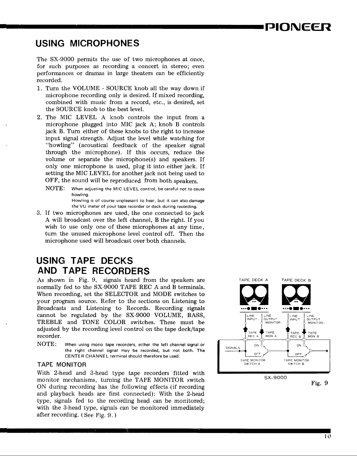
As shown
TAPE DECKS
RECORDERS
in Fig.
9,
signals heard from
the
speakers
are
normally fed to the SX-9000 TAPE REC A and B terminals.
When recording, set the SELECTOR
your program
Broadcasts and
cannot
be
TREBLE
adjusted by the
source. Refer
Listening
regulated
by the SX-9000 VOLUME,
to the
to Records. Recording signals
and TONE COLOR switches.
recording level
control on the tape deck/tape
MODE switches
and
sections
on
These must be
Listening
BASS,
to
to
recorder.
NOTE: When
the right channel signal may
CENTER CHANNEL
using mono tape
recorders,
terminal should
either
be
the
recorded,
therefore
left
but
be
channel
not
both.
used.
signal
The
or
TAPE MONITOR
With 2-head
monitor mechanisms,
ON during recording
playback
and
type, signals fed
with the 3-head type, signals
after recording.
and 3-head type tape recorders
TAPE MONITOR
effects
connected): With the 2-head
head
can
be
heads
to the
turning the
has the following
first
are
recording
can be monitored immediately
(
See
Fig.
9.
)
fitted with
switch
(if
recording
monitored;
...aro.--
TAPE
...oIa---
sx-9000
DECK
B
10
PLAYBACK
.
Turn TAPE
VOLUME,
the desired
o
When
position of the SELECTOR
the
MIXED
When
tape
the microphone
the
this
the tape
By using
of a tape,
etc. and
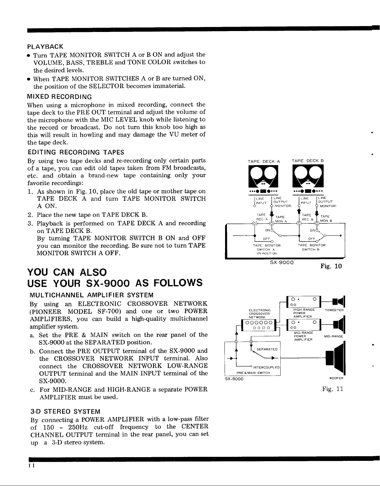
favorite recordings:
using a
deck to
record or
will
EDITING
shown in
1. As
TAPE DECK A and turn TAPE MONITOR SWITCH
A ON.
2. Place the
3. Playback
on TAPE
By tuming
you
can monitor the
MONITOR SWITCH A OFF.
MONITOR
BASS,
levels.
TAPE
RECORDING
deck.
MONITOR
microphone
the PRE OUT
with the
broadcast.
in howling and
result
RECORDING
two tape decks
you
can edit
obtain
a
Fig. 10,
new tape on TAPE
performed on TAPE DECK A and
is
DECK B.
TAPE
SWITCH
TREBLE
SWITCHES
in mixed
terminal
MIC LEVEL
Do
TAPES
and
old tapes taken
brand-new tape containing
place
MONITOR SWITCH B ON
recording. Be sure
A or B ON
and TONE
A or B
becorries
recording,
and
knob
not turn this
may damage
re-recording only certain
old tape or mother
the
DECK B.
and adjust
COLOR
immaterial.
adjust the volume
from
not
switches
are turned
connect
listening
while
knob too high as
VU meter of
the
FM broadcasts,
only
recording
and
turn TAPE
to
YOU CAN ALSO
the
to
ON,
the
of
to
parts
your
tape on
OFF
sx-9000
...oro---
Fig.
10
USE
MULTICHANNEL AMPLIFIER
By using
(PIONEER
AMPLIFIERS,
amplifier
a. Set the
b. Connect
YOUR
an
system.
PRE &
SX-9000
the
connect the
OUTPUT
at the
the PRE OUTPUT
CROSSOVER
SX-gOOO
ELECTRONIC
MODEL
you
terminal and the
SF-700)
build a
can
MAIN switch
SEPARATED
NETWORK
CROSSOVER
MAIN
sx-g000.
c. For
3.D STEREO
By
of
CHANNEL
up
MID-RANGE and
AMPLIFIER
connecting
-
3-D
250H2
OUTPUT
stereo
150
a
must be used.
SYSTEM
POWER
a
system.
HIGH-RANGE
AMPLIFIER
cut-off
terminal
frequency
AS
SYSTEM
CROSSOVER
and one
high-quality
on the rear
position.
terminal
NETWORK
in the
FOLLOWS
or two POWER
of the SX-9000
INPUT terminal.
INPUT
a separate POWER
with
to
panel,
rear
NETWORK
multichannel
panel
of the
Also
LOW-RANGE
terminal
low-pass
a
the
of the
CENTER
you
can
filter
and
set
sx-9000
oooooo
oooo
TJIONEEFI
CONDITIONS
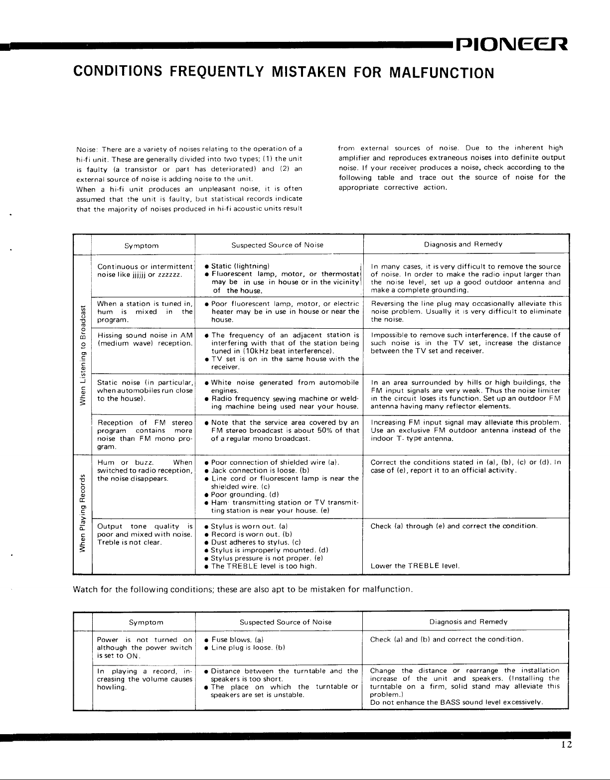
Noise: There are
hi-f i unit.
is faulty
external
When a
assumed
that the
sourceof
Continuous or
noise like
When a station
hum is mixed
a
o
program.
E
o
Hissing sound
m
(medium
o
g
o
'?
.J
Static
q
when automobiles
o
!
to the house).
=
Reception of
program contains more
noise
gram.
Hum
switched to radio
the
E
o
E.
o
.=
o
Output
poor
o
Treble is not clear.
=
a
These are
(a
transistor
hi-fi unit
that the
maiority of
SVmptom
jjjjli
wave)
noise
FM mono
than
buzz. When
or
noise
disappears.
tone
and mixed with noise.
FREQUENTLY
variety
generalty
noise isadding noiseto
produces
unit
or
(in
noises
of
divided
part
or
is
faulty, but
produced
noises
intermitten
zzzzzz.
is tuned in,
in the
noise in
AM
reception.
particular,
run close
FM
stereo
pro-
reception,
quality
MISTAKEN
relating to the operation
into two types;
has deteriorated)
the unit.
unpleasant
an
in hi-f i acoustic
.
o
r Poor fluorescent
I
o TV set
a
r Radio frequency
a
a
. Jack connection
o Line cord or
o
a
is
.
. Record
a Dust adheres
.
a Stylus
r
noase, it
statistical
Static
Fluorescent lamp,
may be
of
heater may
house.
The frequency of an adjacent
interfering with that of the station being
tuned in
rece iver.
White noise
engi
ing machine
Note that
FM
of a
Poor connection of shielded wire
shielded wire.
Poor
Ham
ting station is near
Stylus
Stylus
The TREBLE
records
Suspected
(lightning)
in
use
the house.
be
(10kHz
is
on
nes.
being
the
stereo broadcast
regular mono
grounding.
transmitting station or TV
is worn out.
is
worn out.
to
is improperly mounted.
pressure
of a
(1)
the unit
(2)
and
unats
in the same house with the
generated
service area covered by an
f luorescent
(c)
level is
an
is
often
indicate
result
of Noise
Source
motor, or thermostat
in house
lamp,
in
is not
motor, or
in house or near the
use
beat interference).
from automobile
machine or weld-
sewing
used near
is
about 50% of
broadcast.
(b)
is loose.
(d)
your
house.
(a)
(b)
(c)
stvlus.
proper.
hiqh.
too
in
or
lamo
FOR
from
external
amplif
noise. lf
following table and
appropriate
the vicinity
electric
station is
your
house.
that
{a).
is near the
transmit-
(e)
(d)
(e)
MALFUNCTION
ier and reproduces extraneous
sources of
your
receivel
corrective action.
In manv cases,
noise. In
of
the noise
make a complete
Reversing the
noise
tne norse.
lmpossible to remove such interference. lf the cause
such
between
In an
FM input signals are very weak.
in the
antenna
Increasing
Use
indoor
Correcr
case of
Check
Lower
level,
problem.
noise is in the
the
area
circuit
having many reflector
FM input
an exclusive FM outdoor antenna
tvpe
T-
the conditions
(e),
(a)
through
the
TREBLE
nolse. Due
produces
trace out
order
line
TV
surrounded by hills or high buildings, the
loses its function.
report it to an ofJicial activity.
a
Diagnosis
it is
very diff
to
make
set up a
grounding
plug
may occasionally alleviate this
it is very
Usually
TV
set
receiver.
and
signal may alleviate
antenna.
stated in
(e)
and correct
level.
to the inherent
noises into def inite output
noise, check according tothe
the source of noise
Remedy
and
icult
remove
to
the radio input larger than
good
outdoor antenna and
difficult
set. increase the
Thus
Set
elements.
(a), (b). (c)
the condation.
the source
to
the noise limiter
up an outdoor
this
instead
or
high
for
the
eliminate
of
distance
FM
problem.
of the
(d).
ln
Watch for
the
Power is not
although the
rs
set
playing
In
creasing the volume
howling.
following
Symptom Suspected
to
ON.
conditions; these
turned
power
a record, in-
on
switch
causes
o
. Line
a
a
are also apt to be mistaken
Fuse
blows.
plug
is
Distance between the turntable
soeakers
The
soeakers are set
is
place
Source of
(a)
(b)
loose.
too short.
which the
on
is
unstable.
Noise
and the
turntable
for malfunction.
Diagnosis and Remedy
(a)
(b)
Check
Change
increase of the unit and speakers.
or
turntable on
oroblem.)
Do not enhance
the distance or
and correct
and
a firm, solid stand
the
BASS
sound
the
condition.
rearrange the
(lnstalling
may alleviate
level
excessavely.
installataon
the
this
TZ

SPECIFICATIONS
SEMICONDUCTORS
Audio Section
Transistors
Diodes
Tuner Section
IC's
FET
Transistors
Diodes
47
11
5
t12
11
AUDIO
Music
Continuous
Output
driven)
Continuous
Output
driven)
Harmonic
Damping
Frequency
Power
Hum
Sensitivity and
(at
power
Output
Terminals
Equalization
BASS
TREBLE
Filters
SECTION
Power Output
Power
(Each
Power
(Both
Distortion
Factor
Response
Bandwidth
Noise
and
1kHz, continuous
output)
Jacks
Curve
Control
Control
channel
channel
Impedance
and
8A
rating)
4A 240 watts total
Be
4a
8O 50w
4A 60w
Less than
continuous
30
l-OHz to 35kHz.
10Hz to
PHONO MAG
AUX
PHONO
AUX
TAPE
MICROPHONE
MAIN
150 watts total
62wl62w
85w/85w
(at
8f2, lkHz)
.............more than
...............2.5mV,
(1,2)
..............160mV.
MONITOR
..............160mV.
...............1.6mV,
INPUT
............500mV,
Speakers
Stereo
TAPE
TAPE
(DIN
PRE
PHONO.....RIAA
+12.5dB,
+9dB.
LOW.......Cut
HIGH.....Cut
Headphones
RECording
REC/P.B.
type)
OUTPUT
-11dB
(1kHz)
(1kHz)
+
50w
+
60w
0.57o
power
35kHz
more
(1,2)
MAG
(A,B,C)
-14dB
(at
12dB
(lkHz)
(lkHz)
tldB
(IHF
(A,B)
6dB
(at
output)
rating)
than B0dB
100dB
(A,B)
180kQ
16 ohms
4 to
Jacks
Jacks
Connector
500mV.
(at
50Hz)
10kHz)
(at
(at
LOkHz)
(IHF
1kHz,
50kQ
50kA
5OkO
65kO
(A,B)
(A,B)
13kSl
50Hz)
 Loading...