


SCSI-2

CD-ROM
SCSI-2 Command Set
Reference Manual
Version 3.1
(OB-U0077C)
June 26, 1997
Pioneer Electronic Corporation
Pioneer New Media Technologies, Inc.

CD-ROM
SCSI-2 Command Set
Reference Manual
Version 3.1
(OB-U0077C)

This manual is copyrighted with all rights reserved. No part of this document may be reprinted,
reproduced, translated or utilized in any form or by any means now known or hereafter invented
including, but not limited to, any electronic, mechanical, photocopying and recording or information
storage and retrieval system means, without the express written permission from Pioneer Electronic
Corporation or its affiliates.
Every effort has been made to ensure that the information in this manual is accurate. Pioneer is not
responsible for printing or clerical errors.
Information in this document is subject to change without notice.
Specifications and design are subject to improve or be changed without notice.
Copyright © 1997 Pioneer Electronic Corporation, Pioneer New Media Technologies, Inc.
Document No. SCSI2CD31S001-0697
Simultaneously printed in Japan and the United States of America.
Mention of third-party products is for informational purposes only and contributes neither an
endorsement nor a recommendation. Pioneer assumes no responsibility with regard to the performance or
use of these products.
No investigation has been made of common-law trademark rights in any word. Words that are known to
have current registrations are shown with an initial capital. Many, if not all, hardware and/or software
products referenced in this manual are identified by their trade names. Most, if not all, of these
designations are claimed as legally protected trademarks by the companies that make the product. It is
not Pioneer’s intent to use any of these names generically and cautions the reader to investigate any
claimed trademark before using it for any purpose other than to refer to the product to which the
trademark is attached.
Pioneer makes no warranty of any kind, expressed or implied, about the contents of this manual, the
merchantability of the product or the product’s fitness for any particular purpose.
Every precaution has been taken in the preparation of this manual. Although we tried to thoroughly
check that all instructions in this manual are accurate and correct, Pioneer can not be and is not
responsible, in whole or in part, for any damage or loss to your data and/or equipment that results from
your use of this document or from any information contained herein including, but not limited to, any
errors, omissions or typos that may have resulted in an incorrect operation or installation.

FCC INFORMATION
The equipment described in this manual has been tested and found to comply with the limits for a Class
B digital device in accordance with the specifications in Part 15 of FCC rules. These specifications are
designed to provide reasonable protection against radio and television reception interference in a
residential installation. There is no guarantee that interference will not occur in a particular installation.
To determine if your CD-ROM drive is causing interference, turn the drive off. If the interference stops,
it was most likely caused by the drive. To eliminate the interference, you may try one or more of the
following corrective measures:
• verify the cables and connectors between components are shielded.
• increase separation between the drive and components.
• connect the drive into an outlet or circuit different from that which the components are
connected.
• consult dealer or experienced radio/television technician for help.
The Federal Communications Commission offers a handbook that may help you with eliminating
interference. The handbook is titled Interference Handbook (stock number 004-000-00493-1) and may
be ordered from the U.S. Government Printing Office, Washington, D.C. 20402.
WARNING: Any changes or modifications to this product that are not authorized by Pioneer could void
the FCC Certification and negate the user’s authority to operate the equipment.
DOC CLASS B COMPLIANCE
This digital apparatus does not exceed the Class B limits for radio noise emissions from digital apparatus
set out in the radio interference regulations of the Canadian Department of Communications.

- -
i
Table of Contents
LIST OF TABLES ..............................................................................................................................iv
REVISION HISTORY...................................................................................................................... viii
1. PREFACE.................................................................................................................................... 1
1.1 DRM/DR-U Series ......................................................................................................................1
1.2 Drives Supported by this Manual ................................................................................................3
1.3 SCSI Protocol.............................................................................................................................4
1.3.1 Command Link/Control Field...........................................................................4
1.3.2 Disconnect/Reselect..........................................................................................4
1.3.3 Status Phase...................................................................................................... 5
1.3.4 In-Phase/Out-Phase Messages........................................................................... 5
1.4 Address Format for Answering Occasion (MSF bit)....................................................................7
1.5 Sample Command .......................................................................................................................7
2. COMMANDS ..............................................................................................................................9
2.1 Audio Scan (1) (CDh)...............................................................................................................13
2.2 Audio Scan (2) (BAh)...............................................................................................................17
2.3 Change Definition (40h)............................................................................................................19
2.4 Inquiry (12h) .............................................................................................................................21
2.5 Mode Select(6) (15h) ................................................................................................................25
2.6 Mode Select(10) (55h) ..............................................................................................................29
2.7 Mode Sense(6) (1Ah)................................................................................................................31
2.8 Mode Sense(10) (5Ah)..............................................................................................................35
2.9 Mode Select/Sense Parameters..................................................................................................37
2.9.1 Error Recovery Parameters.............................................................................39
2.9.2 Verify Error Recovery Page............................................................................45
2.9.3 Peripheral Device Page................................................................................... 47
2.9.4 Medium Types Supported Page ......................................................................49
2.9.5 CD-ROM Parameters Page............................................................................. 51
2.9.6 CD-ROM Audio Control Parameters.............................................................. 53
2.9.7 CD-ROM Capabilities and Mechanical Status Page........................................ 55
2.9.8 Drive Speed Page ...........................................................................................61
2.9.9 Logical Unit Assignment Page........................................................................ 63
2.10 Pause/Resume (4Bh).................................................................................................................65
2.11 Play Audio(10) (45h) ................................................................................................................67
2.12 Play Audio(12) (A5h) ...............................................................................................................69
2.13 Play Audio MSF (47h)..............................................................................................................71

- ii -
2.14 Play Audio Track Index (48h)................................................................................................... 73
2.15 Play Audio Track Relative(10) (49h)........................................................................................ 75
2.16 Play Audio Track Relative(12) (A9h) ....................................................................................... 77
2.17 Prevent/Allow Media Removal (1Eh)....................................................................................... 79
2.18 Read(6) (08h) ........................................................................................................................... 81
2.19 Read(10)................................................................................................................................... 83
2.20 Read Buffer (3Ch).................................................................................................................... 85
2.21 Read CD-ROM Capacity (25h) ................................................................................................. 87
2.22 Read CD (BEh) ........................................................................................................................ 89
2.23 Read CD MSF (B9h)................................................................................................................ 95
2.24 Read CDP (E4h) ....................................................................................................................... 97
2.25 Read Drive Status (E0h)........................................................................................................... 99
2.26 Read header (44h)....................................................................................................................103
2.27 Read Sub-Channel (42h)..........................................................................................................105
2.28 Read TOC (43h)......................................................................................................................113
2.29 Read Diagnostic Results (1Ch)................................................................................................119
2.30 Release (17h)...........................................................................................................................121
2.31 Request Sense (03h) ................................................................................................................123
2.32 Reserve (16h) ..........................................................................................................................129
2.33 Rezero Unit (01h)....................................................................................................................131
2.34 Seek(6)....................................................................................................................................133
2.35 Seek(10) (2Bh)........................................................................................................................135
2.36 Send Diagnostic (1Dh) ............................................................................................................137
2.37 Set CD-ROM Speed(1) (DAh).................................................................................................139
2.38 Set CD-ROM Speed(2) (BBh).................................................................................................141
2.39 Start/Stop Unit (1Bh)...............................................................................................................143
2.40 Stop Play/Scan (4Eh)...............................................................................................................145
2.41 Test Unit Ready (00h) .............................................................................................................147
2.42 Verify(10) (2Fh)......................................................................................................................149
2.43 Verify(12) (AFh).....................................................................................................................151
2.44 Write Buffer (3Bh) ..................................................................................................................153
2.45 Write CDP (E3h).....................................................................................................................155
2.46 Read CD-DA (D8h) .................................................................................................................157
2.47 Read CD-DA MSF (D9h)........................................................................................................161
2.48 READ CD-XA (DBh)..............................................................................................................163
2.49 Read All SubCode (DFh).........................................................................................................165
APPENDIX A PIONEER CD-ROM DRIVES - AUDIO FUNCTIONS.............................................I
APPENDIX B AUDIO PLAYER COMMANDS.................................................................................I

- -
iii
APPENDIX C DRIVE VERSION DIFFERENCES............................................................................I
APPENDIX D PRODUCTS DEFAULT DATA...................................................................................I
D.1 Product data of Applied Model Number 3 (Inquiry Data).............................................................I
D.2 CD-ROM ABILITY MECHANICAL STATUS PAGE DEFAULT DATA...............................III
APPENDIX E CD-ROM COMMAND LIST (BY CODE)..................................................................I

- iv -
LIST OF TABLES
TABLE 1-0 MODELS OF DRM/DR-U SERIES SUPPORTING SCS-2 COMMAND SET....................................................2
T
ABLE 1-2 DRIVE VERSIONS SUPPORTED BY THIS MANUAL ....................................................................................2
T
ABLE 1-5 SAMPLE COMMAND...................................................................................................................................6
T
ABLE 2-0 SCSI-2 COMMAND LIST (BY NAME).......................................................................................................8
TABLE 2-0A CD-ROM MODE PAGE CODE LIST...................................................................................................... 10
TABLE 2-1 AUDIO SCAN (1) ..................................................................................................................................... 12
TABLE 2-1A LOGICAL BLOCK ADDRESS FORMAT (TYPE = 00B)................................................................................ 12
T
ABLE 2-1B AMIN, ASEC AND AFRAME ADDRESS FORMAT (TYPE = 01B) .......................................................... 14
T
ABLE 2-1C TRACK NUMBER ADDRESS FORMAT (TYPE = 10B) ................................................................................. 14
TABLE 2-2 AUDIO SCAN (2) ..................................................................................................................................... 16
T
ABLE 2-3 CHANGE DEFINITION............................................................................................................................ 18
T
ABLE 2-4 INQUIRY.................................................................................................................................................. 20
TABLE 2-4A INQUIRY DATA FORMAT .....................................................................................................................20
T
ABLE 2-4B DRIVE SPECIFIC STRINGS .................................................................................................................... 22
TABLE 2-5 MODE SELECT(6) (15H)...........................................................................................................................24
TABLE 2-5A MODE SELECT(6) HEADER AND PARAMETER LIST ................................................................................24
T
ABLE 2-5B BLOCK DESCRIPTOR ........................................................................................................................... 26
T
ABLE 2-5C PAGE DESCRIPTOR .............................................................................................................................26
TABLE 2-6 MODE SELECT(10) (55H).......................................................................................................................28
T
ABLE 2-7 MODE SENSE(6) (1AH)..........................................................................................................................30
TABLE 2-7A MODE SENSE DATA HEADER...............................................................................................................30
T
ABLE 2-7B BLOCK DESCRIPTOR ........................................................................................................................... 30
T
ABLE 2-7C MEDIA TYPE CODE ............................................................................................................................32
T
ABLE 2-7D PAGE DESCRIPTOR FORMAT ................................................................................................................32
TABLE 2-8 MODE SENSE(10) (5AH)........................................................................................................................34
T
ABLE 2-9 MODE SELECT/SENSE PARAMETERS ................................................................................................. 36
TABLE 2-9A MODE PAGE CODES FOR CD-ROM ..................................................................................................... 36
T
ABLE 2-9B MODE PAGE FORMAT .........................................................................................................................36
TABLE 2-9-1 PAGE CODE 01H - ERROR RECOVERY PARAMETERS .............................................................................38
TABLE 2-9-1A VALID COMBINATIONS OF THE ERROR RECOVERY PARAMETERS ............................................................ 38
T
ABLE 2-9-1B ERROR RECOVERY DESCRIPTIONS........................................................................................................ 40
T
ABLE 2-9-1B ERROR RECOVERY DESCRIPTIONS (CONTINUED) .................................................................................... 41
T
ABLE 2-9-1B ERROR RECOVERY DESCRIPTIONS (CONTINUED) .................................................................................... 42
TABLE 2-9-2 PAGE CODE 07H - VERIFY ERROR RECOVERY PAGE FORMAT..............................................................44
TABLE 2-9-3 PAGE CODE 09H - PERIPHERAL DEVICE PAGE FORMAT ........................................................................46
TABLE 2-9-3A INTERFACE IDENTIFIER CODES ............................................................................................................ 46
TABLE 2.9.4 PAGE CODE 0BH - MEDIUM TYPES SUPPORTED PAGE FORMAT ........................................................... 48
T
ABLE 2-9-5 PAGE CODE 0DH - CD-ROM PARAMETERS PAGE FORMAT...................................................................50

- -
v
TABLE 2-9-5A INACTIVITY TIMER MULTIPLIER VALUE............................................................................................... 50
TABLE 2-9-6 PAGE CODE 0EH - CD-ROM AUDIO CONTROL PARAMETERS STATUS FORMAT.................................. 52
TABLE 2-9-6A OUT PORT CHANNEL SELECT PARAMETERS..........................................................................................52
TABLE 2-9-7 PAGE CODE 2AH - CD-ROM CAPABILITIES AND MECHANICAL STATUS PAGE FORMAT.................... 54
TABLE 2-9-7A PARAMETER DESCRIPTION .................................................................................................................. 56
T
ABLE 2-9-7B EXAMPLE DATA RATES ......................................................................................................................57
TABLE 2-9-8 PAGE CODE 31H - DRIVE SPEED PAGE.................................................................................................... 60
TABLE 2-9-8A SPEED FIELD VALUES.........................................................................................................................60
TABLE 2-9-9 PAGE CODE 3EH - LOGICAL UNIT ASSIGNMENT LIST ........................................................................... 62
T
ABLE 2-10 PAUSE/RESUME (4BH).......................................................................................................................... 64
T
ABLE 2-11 PLAY AUDIO(10) (45H).......................................................................................................................... 66
T
ABLE 2-12 PLAY AUDIO(12) (A5H)......................................................................................................................... 68
T
ABLE 2-13 PLAY AUDIO MSF (47H) ....................................................................................................................... 70
T
ABLE 2-14 PLAY AUDIO TRACK INDEX (48H) ..................................................................................................... 72
T
ABLE 2-15 PLAY AUDIO TRACK RELATIVE(10) (49H)........................................................................................ 74
T
ABLE 2-16 PLAY AUDIO TRACK RELATIVE(12) (A9H)........................................................................................ 76
T
ABLE 2-17 PREVENT/ALLOW MEDIA REMOVAL (1EH) ...................................................................................... 78
T
ABLE 2-18 READ(6) (08H) ......................................................................................................................................... 80
T
ABLE 2-19 READ(10)................................................................................................................................................. 82
T
ABLE 2-20 READ BUFFER (3CH).............................................................................................................................. 84
TABLE 2-20A READ BUFFER HEADER....................................................................................................................... 84
TABLE 2-21 READ CD-ROM CAPACITY (25H).......................................................................................................... 86
TABLE 2-21A READ CAPACITY DATA.......................................................................................................................86
TABLE 2-22 READ CD (BEH) ...................................................................................................................................... 88
TABLE 2-22A READ-CD, EXPECTED SECTOR TYPE FIELD DEFINITION ...................................................................... 88
T
ABLE 2-22B READ CD, HEADER CODE FIELD DEFINITION ..................................................................................... 90
T
ABLE 2-22C READ CD, ERROR FLAG FIELD DEFINITION........................................................................................ 90
T
ABLE 2-22D READ CD, SUB CHANNEL DATA SELECTION FIELD DEFINITION............................................................92
T
ABLE 2-22E NUMBER OF BYTES RETURNED BASED ON DATA SELECTION FIELD ........................................................92
TABLE 2-23 READ CD MSF (B9H) .............................................................................................................................. 94
T
ABLE 2-24 READ CDP (E4H)..................................................................................................................................... 96
T
ABLE 2-25 READ DRIVE STATUS (E0H) ................................................................................................................. 98
TABLE 2-25A PAGE HEADER ................................................................................................................................... 98
T
ABLE 2-25B DRIVE STATUS DATA FORMAT .......................................................................................................... 100
T
ABLE 2-25C AUDIO PLAY STATUS FORMAT .......................................................................................................... 100
TABLE 2-26 READ HEADER (44H) ........................................................................................................................... 102
TABLE 2-26A HEADER DATA FORMAT ................................................................................................................... 102
T
ABLE 2-26B CD-ROM DATA MODE CODES......................................................................................................... 102
TABLE 2-27 READ SUB-CHANNEL (42H)................................................................................................................ 104
TABLE 2-27A SUB CHANNEL DATA HEADER........................................................................................................... 104

- vi -
TABLE 2-27B SUB-CHANNEL Q MODE INFORMATION............................................................................................... 106
T
ABLE 2-27C AUDIO STATUS ................................................................................................................................106
T
ABLE 2-27D ADR SUB-CHANNEL Q FIELD........................................................................................................... 108
T
ABLE 2-27E SUB-CHANNEL Q CONTROL FIELD .................................................................................................... 108
T
ABLE 2-27F CD-ROM CURRENT POSITION DATA BLOCK .....................................................................................108
T
ABLE 2-27G MEDIA CATALOG NUMBER DATA BLOCK............................................................................................ 110
T
ABLE 2-27H TRACK INTERNATIONAL STANDARD RECORDING CODE(ISRC) DATA BLOCK ...................................... 110
TABLE 2-28 READ TOC (43H) ................................................................................................................................... 112
TABLE 2-28A TOC DATA WITH FORMAT=00B....................................................................................................... 112
T
ABLE 2-28B TRACK DESCRIPTORS........................................................................................................................ 112
T
ABLE 2-28C TOC DATA WITH FORMAT=01B....................................................................................................... 114
T
ABLE 2-28D TRACK DESCRIPTORS........................................................................................................................ 114
T
ABLE 2-28E TOC DATA WITH FORMAT=10B (DRM-602X ONLY) ......................................................................... 114
T
ABLE 2-28F TRACK DESCRIPTORS........................................................................................................................ 116
TABLE 2-29 RECEIVE DIAGNOSTIC RESULTS (1CH)............................................................................................ 118
TABLE 2-29A DIAGNOSTIC RESULTS DATA FORMAT................................................................................................ 118
TABLE 2-30 RELEASE (17H) .....................................................................................................................................120
T
ABLE 2-31 REQUEST SENSE (03H) ........................................................................................................................122
TABLE 2-31A EXTENDED SENSE DATA FORMAT ....................................................................................................... 122
T
ABLE 2-31B SUPPORTED SENSE KEYS.................................................................................................................... 124
T
ABLE 2-31C SUPPORTED ADDITIONAL SENSE CODES AND ADDITIONAL SENSE CODE QUALIFIERS ................................. 125
TABLE 2-32 RESERVE (16H) ..................................................................................................................................... 128
T
ABLE 2-33 REZERO UNIT (01H) ............................................................................................................................. 130
T
ABLE 2-34 SEEK(6) (0BH)........................................................................................................................................ 132
T
ABLE 2-35 SEEK(10) (2BH)...................................................................................................................................... 134
T
ABLE 2-36 SEND DIAGNOSTIC (1DH) ................................................................................................................... 136
TABLE 2-36A SEND DIAGNOSTIC DATA FORMAT..................................................................................................... 136
TABLE 2-37 SET CD-ROM SPEED(1) (DAH)............................................................................................................. 138
T
ABLE 2-38 SET CD-ROM SPEED(2) (BBH)............................................................................................................. 140
TABLE 2-38A WRITE BUFFER HEADER ................................................................................................................... 152
TABLE 2-39 START/STOP UNIT (1BH).....................................................................................................................142
T
ABLE 2-40 STOP PLAY/SCAN (4EH) ......................................................................................................................144
T
ABLE 2-41 TEST UNIT READY (00H)..................................................................................................................... 146
T
ABLE 2-42 VERIFY(10) (2FH).................................................................................................................................. 148
T
ABLE 2-43 VERIFY(12) (AFH)................................................................................................................................. 150
T
ABLE 2-44 WRITE BUFFER (3BH)..........................................................................................................................152
T
ABLE 2-45 WRITE CDP (E3H) ................................................................................................................................. 154
T
ABLE 2-46 READ CD-DA (D8H)..............................................................................................................................156
T
ABLE 2-47 READ CD-DA MSF (D9H)...................................................................................................................... 160
T
ABLE 2-48 READ CD-XA (DBH) .............................................................................................................................162

- -
vii
TABLE 2-49 READ ALL SUBCODE (DFH)................................................................................................................ 164
T
ABLE D-1A DR-U124X INQUIRY DATA FORMAT..........................................................................................................I
T
ABLE D-1B DR-UA124X INQUIRY DATA FORMAT.......................................................................................................I
T
ABLE D-1C DRM-624X INQUIRY DATA FORMAT........................................................................................................II
T
ABLE D-2A PAGE CODE 2AH : CD-ROM CAPABILITIES AND MECHANICAL STATUS PAGE DEFAULT DATA......... III
T
ABLE E-1 CD-ROM COMMAND LIST BY CODE.........................................................................................................I

- viii -
REVISION HISTORY
Version Date Section/Page Description
1.0 09.07.93 N/A Initial release
2.0 07.20.94 Title
Sections 1.1 - 1.2
Section 1.4
Sections 2.46 - 2.49
Addition of DRM-602X Vendor Unique
Commands
3.0 02.08.95 Sections 1.1 - 1.2
Section 1.4
Section 2.1
Section 2.9.7
Sections 2.22 - 2.23
Section 2.37
Section 2.40
Sections 2.46 - 2.49
Addition of models DR-124X and DRM-624X
Addition of Appendix D
3.1 06.26.97 Sections 1.0 - 1.2
Section 1.4
Sections 2.46 - 2.49
Addition of models DR-A10X, DR-411, DR-
U10X, DR-433, DR-A12X, DR-444, DR-
U12X, DR-466, DR-A24X, DR-511, DR-
U24X, DR-533

Preface
- 1 -
1. PREFACE
These specifications define the SCSI command set that defines the interface between a host computer and
such primary devices as CD-ROM drives and CD-R writers.
These are the control functions for the Pioneer DRM/DR-U series CD-ROM drives. For specific models,
refer to Section 1.1 below.
For details of the common standard of SCSI, refer to ANSI SCSI-2 working draft X3T9.2 revision 10K.
For details regarding the use of the compact disc as a SCSI CD-ROM device, refer to the proposal made
after the ANSI SCSI-2 working draft X3T9.2 revision 10K.
For Compact Disc, CD-ROM disc, and CD-R disc specifications, refer to the Red Book, Yellow Book and
Orange Book Part2.
For file system specifications, refer to ISO 9660.
For details about the use of SCSI Bus, refer to the installation manuals of the particular drives.
For more information on player control commands (mnemonic commands), refer to Appendix B of this
document and/or Pioneer Industrial LaserDisc Player (any model) User’s Manuals.
THESE SPECIFICATIONS ARE SUBJECT TO CHANGE WITHOUT NOTICE.
1.1 DRM/DR-U Series
The six-disc DRM series drives are SCSI-2
1
CD-ROM minichangers using a single movable
optical assembly and a removable Pioneer-developed 6-disc CD magazine. Six discs may be
stored in individual trays in the magazine. Each tray swings out of the magazine into the drive
assembly. Only one disc may be read at a time. The minichanger appears on the SCSI bus as one
SCSI ID with six (6) logical units (0-5), one logical unit assigned per disc. The assignment of
logical units to discs may be changed at any time.
1
DRM-604X is the only minichanger that supports both the SCSI-1 and SCSI-2 command sets. Please refer to Pioneer’s DRM-600
Series SCSI Command Reference Manual for details on the SCSI-1 command set.

CD-ROM SCSI-2 COMMAND REFERENCE MANUAL VERSION 3.1 (OB-U0077C)
- 2 -
TABLE 1-0 MODELS OF DRM/DR-U SERIES SUPPORTING SCS-2 COMMAND SET
Model Number Voltage Requirements
DRM-602X 100 v ~ 230 v
DRM-604X 100 v ~ 230 v
DRM-624X 100 v ~ 230 v
DRM-1804X 100 v ~ 230 v
DR-D504X DRM-5004X 500-disc Autochanger built-in use
DR-U124X +5 v. +12 v
DR-UA124X +5 v. +12 v ATA BUS mode1
DR-A10X +5 v. +12 v ATA BUS mode1
DR-U10X +5 v. +12 v
DR-411 +5 v. +12 v OEM version of DR-A10X
DR-433 +5 v. +12 v OEM version of DR-U10X
DR-A12X +5 v. +12 v ATA BUS mode1
DR-U12X +5 v. +12 v
DR-444 +5 v. +12 v OEM version of DR-A12X
DR-466 +5 v. +12 v OEM version of DR-U12X
DR-A24X +5 v. +12 v ATA BUS mode1
DR-U24X +5 v. +12 v
DR-511 +5 v. +12 v OEM version of DR-A24X
DR-533 +5 v. +12 v OEM version of DR-U24X
TABLE 1-2 DRIVE VERSIONS SUPPORTED BY THIS MANUAL
Model Number Vendor Product Data Revision Number
DRM-602X Pioneer CD-ROM DRM-602X 2901 or greater
DRM-604X Pioneer CD-ROM DRM-604X 2403 or greater
DRM-624X Pioneer CD-ROM DRM-624X 0100 or greater
DRM-1804X Pioneer CD-ROM DRM-1804X 0100 or greater
DR-D504X Pioneer CD-ROM DR-D504X 2405 or greater
DR-U124X Pioneer CD-ROM DR-U124X 0100 or greater
DR-UA124X Pioneer CD-ROM DR-UA124X 0100 or greater
DR-A10X Pioneer CD-ROM DR-A10X 0100 or greater
DR-U10X Pioneer CD-ROM DR-U10X 0100 or greater
DR-411 Pioneer CD-ROM DR-A10X 0100 or greater
DR-433 Pioneer CD-ROM DR-U10X 0100 or greater
DR-A12X Pioneer CD-ROM DR-A12X 0100 or greater
DR-U12X Pioneer CD-ROM DR-U12X 0100 or greater
DR-444 Pioneer CD-ROM DR-A12X 0100 or greater
DR-466 Pioneer CD-ROM DR-A12X 0100 or greater
DR-A24X Pioneer CD-ROM DR-A24X 0100 or greater
DR-U24X Pioneer CD-ROM DR-U24X 0100 or greater
DR-511 Pioneer CD-ROM DR-A24X 0100 or greater
DR-533 Pioneer CD-ROM DR-U24X 0100 or greater

Preface
- 3 -
The DRM-1804X is an 18-disc single drive SCSI-2 CD-ROM changer. It appears on the SCSI
bus as one SCSI ID with two (2) logical units. The single CD-ROM reader is logical unit 0 and
the changer is logical unit 1. For detail information, refer to Pioneer’s DRM-1804X CD-ROM
Jukebox Changer Mechanism Controller SCSI Specifications, document number OB-U0084-B.
The DRM series includes two jukebox changers - the DRM-1004X 100-disc CD-ROM changer
and the DRM-5004X 500-disc CD-ROM changer. For detail information, refer to Pioneer
publications DRM-1004X Series 100-Disc CD-ROM Changer Mechanism Controller
Specifications, document number DSE-S035C and DRM-5004X Series 500-Disc CD-ROM
Changer Mechanism Controller SCSI Specifications, document number OB-U0091-B,
respectively.
The DR-U series are SCSI-2 single disc CD-ROM drives. They appear on the SCSI bus as one
SCSI ID with logical unit 0.
The DR-D504X is a SCSI-2 single drive unit that is mounted into the DRM-5004X 500-disc
jukebox changer. It is assigned one SCSI ID and logical unit 0. Refer to Pioneer’s DRM-5004X
Series 500-Disc CD-ROM Changer Mechanism Controller SCSI Specifications, document
number OB-U0091-B, for further details.
Implementing Pioneer’s LaserDisc player technology, vendor unique SCSI commands support
the alphanumeric player command set allowing CD audio control through use of simple
mnemonic commands. Refer to Appendices A and B for further information.
Table 1.1 on the opposite page lists the models supporting the SCSI-2 command set.
1.2 Drives Supported by this Manual
Refer to Table 1-2 on the opposite page for drive versions that are supported by this manual. To
determine what version your drive is, issue an IQUIRY command, reference Section 2.4. The
drive’s response to the command will be to return the following information about the drive:
Model Number;
Vendor;
Product Data; and
Revision Number.

CD-ROM SCSI-2 COMMAND REFERENCE MANUAL VERSION 3.1 (OB-U0077C)
- 4 -
1.3 SCSI Protocol
The SCSI Protocol outlined in this section applies only to SCSI bus models. It does not support
ATA bus models.
1.3.1 Command Link/Control Field
The Control Field inside the Command Block is defined as:
Bit 7 6 5 4 3 2 1 0
Vendor Unique Reserved Flag Link
The Command Link function is not supported by the DRM/DR-U Series. Set Flag and
Link bits to “0” (FALSE).
Set the RelAdr (Relative Address) bit, bit 0 of byte 1, inside the Command Block to
“0” (FALSE).
1.3.2 Disconnect/Reselect
Selection time-out period is 250 ms.
If the initiator does not respond to reselection within the time-out period, the drive will
release the bus for a minimum of 200 ms. The drive will then repeat the
arbitration/reselection sequence until the initiator responds, issues BUS DEVICE
RESET, or until the SCSI bus is reset. During a reselection retry, the drive will return
BUSY to selection requests from any initiator.
During execution of audio commands, if the disconnect/reselect function is selected,
the drive disconnects from the initiator before execution a SEEK or other operation
that requires head movement. When the selected address is located, the drive reselects
the initiator and begins audio playback. The time needed for the reselection procedure
is dependent upon the status of the SCSI bus. Audio playback may begin before the
reselection is complete. Refer to Appendix A for more information.

Preface
- 5 -
1.3.3 Status Phase
Four status conditions are supported. They are
GOOD 00h
CHECK CONDITION 02h
BUSY 08h
RESERVATION CONFLICT 18h
When the IMMED bit is set to “1” (TRUE) in a command block, the drive returns
GOOD when the command is first interpreted. As the command is being executed, the
drive returns BUSY to successive commands until operation of the first command is
complete and the drive is ready to receive a new command.
Refer to Section 2.31 REQUEST SENSE for details on deferred error reporting.
1.3.4 In-Phase/Out-Phase Messages
The DRM/DR-U Series supports only those In-Phase and Out-Phase Messages that are
listed below and on the following page. The drive will return a MESSAGE REJECT
for any messages received other than those listed.
Message Msg 05h + 09h will cause the drive to go to BUS FREE PHASE without a
retry.
Message In-Phase (issued by drive)
COMMAND COMPLETE 00h
SAVE DATA POINTER 02h
DISCONNECT 04h
MESSAGE REJECT 07h
IDENTIFY 80h - FFh
SYNCHRONOUS DATA TRANSFER REQUEST
2
01h
2
From EXTEND MESSAGE (01h)

CD-ROM SCSI-2 COMMAND REFERENCE MANUAL VERSION 3.1 (OB-U0077C)
- 6 -
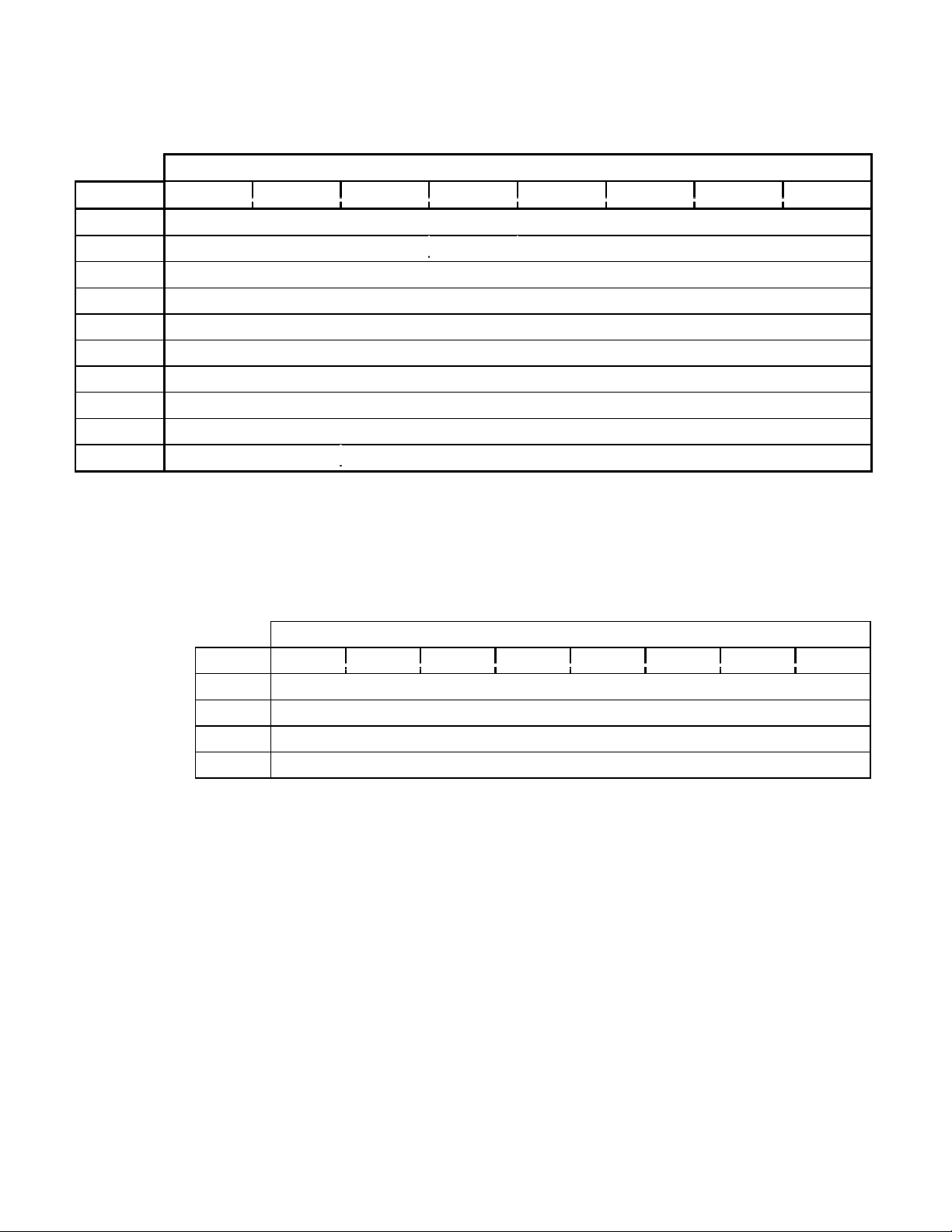
TABLE 1-5 SAMPLE COMMAND
Bit
Byte 7 6 5 4 3 2 1 0
0 Operation Code (XXh)
1 Logical Number Reserved
2 Logical Block Address (MSB)
3 Logical Block Address
4 Logical Block Address
5 Logical Block Address (LSB)
6 Reserved
7 Allocation Length (MSB)
8 Allocation Length (LSB)
9 Reserved
Operation Code : XXh
Logical Unit Number specifies which Logical Unit the command applies to.
Logical Block Address specifies which Logical Block Address (LBA) the operation is to start.
Allocation Length is (depending on the command) the number of Logical Blocks or the number
of bytes that the initiator is expecting to receive from the drive.

Preface
- 7 -
Message Out-Phase (issued by host computer)
INITIATED DEFECTED ERROR 05h
ABORT 06h
NO OPERATION 08h
MESSAGE PARITY ERROR 09h
BUS DEVICE DRIVER
3
0Ch
TERMINATE IO PROCESS 11h
IDENTIFY 80h - FFh
SYNCHRONOUS DATA TRANSFER REQUEST
4
01h
1.4 Address Format for Answering Occasion (MSF bit)
With some commands, it is possible to choose either Logical Block Address or MSF Format
with Address Field of answering data.
MSF bit
if “0” (FALSE), use Logical Block Address as CD-ROM Absolute Address or Track
Relative Address. If Track Relative Address, the MSF bit is indicated by 2s sequences.
if “1” (TRUE), MSF Format is used. Within the shift area, number declines by a positive
number.
1.5 Sample Command
The table on the opposite page outlines the command structure. Some commands apply to the
entire drive. For these commands only, the LUN will be ignored.
Commands with Logical Blocks, e.g. READ, VERIFY, have Allocation Length in Blocks. All
others have Allocation Length in bytes. Some commands use Transfer Length instead of
Allocation Length to specify the number of bytes that the initiator will transfer to the drive.
3
For equipment supporting Change Definition Command, the DRM/DR-U Series drives have a Hardware Reset Option. In this case, the
Change Definition chosen by the SCSI action definition would not be changed or initialized by either the SCSI BUS RESET or BUS
DEVICE RESET message.
4
From EXTEND MESSAGE (01h).

CD-ROM SCSI-2 COMMAND REFERENCE MANUAL VERSION 3.1 (OB-U0077C)
- 8 -
The drive terminates the DATA IN phase when the specified number of bytes have been
transferred or, in the case when the bytes exceed the number of bytes the drive wishes to transfer,
the DATA IN phase is terminated when the number of bytes prepared have been transferred.

Table 2-0 SCSI-2 COMMAND LIST (by Name)
Applied Model Sense Data
Command Name Code
I II III Contents of Information Bytes
Audio Scan (1) BAh --- --- 7 Logical Block Address
Audio Scan (2) CDh yes yes 7 Logical Block Address
Change Definition 40h 1 --- ---
Inquiry 12h yes yes yes
Mode Select(6) 15h 2 2 yes
Mode Select(10) 55h 2 2 yes
Mode Sense(6) 1Ah 2 2 yes
Mode Sense(10) 5Ah 2 2 yes
Pause/Resume 4Bh yes yes yes Logical Block Address
Play Audio (10) 45h yes yes yes Logical Block Address
Play Audio (12) A5h yes yes yes Logical Block Address
Play Audio MSF 47h yes yes yes Logical Block Address
Play Audio Track/Index 48h yes yes yes Logical Block Address
Play Track Relative (10) 49h yes yes yes Logical Block Address
Play Track Relative (12) A9h yes yes yes Logical Block Address
Prevent/Allow Medium Removal 1Eh yes yes yes
Read (6) 08h yes yes yes Logical Block Address
Read (10) 28h yes yes yes Logical Block Address
Read (12) A8h yes yes yes Logical Block Address
Read Buffer 3Ch yes yes yes
Read CD BEh --- --- 3 Logical Block Address
Read CD-DD D8h --- yes 3 Logical Block Address
Read CD MSF B9h --- --- 3 Logical Block Address
Read CD-DA MSF D9h --- yes 3 Logical Block Address
Read CD-XA DBh --- yes yes Logical Block Address
Read All Subcode DFh --- yes 7 Logical Block Address
Read CD-ROM Capacity 25h yes yes yes Logical Block Address
Read Header 44h yes yes yes Logical Block Address
Read Sub-Channel 42h yes yes yes
Read TOC 43h 4 yes yes
Receive Diagnostic Results 1Ch yes yes yes
Release 17h yes yes 5
Request Sense 03h yes yes yes
Reserve 16h yes yes 5
Rezero Unit 01h yes yes yes
Seek (6) 0Bh yes yes yes Logical Block Address
Seek (10) 2Bh yes yes yes Logical Block Address
Send Diagnostic 1Dh yes yes yes
Set CD-ROM Speed (1) BBh --- --- yes
Set CD-ROM Speed (2) DAh yes yes yes
Start/Stop Unit 1Bh yes yes yes
Stop Play/Scan 4Eh --- --- yes
Test Unit Ready 00h yes yes yes
Verify (10) 2Fh yes yes --- Logical Block Address
Verify (12) AFh yes yes --- Logical Block Address
Write Buffer 3Bh yes yes 5
Read CDP E4h yes yes yes
Read Drive Status E0h yes yes yes
Write CDP E3h yes yes yes

Commands
- 9 -
2. COMMANDS
The table on the opposite page lists the commands in the SCSI-2 command set and their corresponding
code, applied model and sense data when applicable.
Applied Model
Applied Model has three values. Each model code corresponds to particular drive models.
I : product models DRM-604X; DRM-1804X; and DR-D504X
II : product model DRM-602X
III : product models DRM-624X; DR-U124X; DR-UA124X; DR-A10X; DR-U10X;
DR-A12X; DR-411; DR-U12X; DR-433; DR-A24X; DR-511; DR-U24X; and
DR-533
Each command is either supported by a drive, indicated by “yes”, not supported by a drive, “---“,
or is supported but with restrictions and/or conditions, “N” where N is a numeric value 1-7.
yes : is supported by all drives corresponding to this Applied Model code.
--- : is not supported by any of the drives corresponding to this Applied Model code.
1 : is not supported by DRM-1804X.
2 : does not support the media type code 4h, 8h, 70h, 71h and 72h. There is limited
action in the CD-ROM Audio Controller Parameter Page (0Eh).
3 : random access is possible with CD-DA data. Buffer Over Flow Error would not
occur. For SUB-CHANNEL READ OUT, support is only when the Beginning
Logical Block Address is FFFFFFFFh and Sub-Channel data. It is unable to
choose the Beginning Logical Block Address or to read out along with other
data.
4 : is not supported by Format Field = 2 (all of Q Sub-Code information).
5 : is not supported by DR-UA124X.
6 : is unable to reassign disc of single type drive.
7 : is not supported by DR-A10X, DR-U10X, DR-411, DR-433, DR-A12X, DR-
U12X, DR-444, DR-466, DR-A24X, DR-U24X, DR-511 and DR-533.
Upon execution of some commands, a Page Code is returned. The table on the next page lists the various
CD-ROM Mode Page Codes.
NOTE: The Applied Model values and the support codes listed above apply to the CD-ROM Mode Page
Code List on the next page. (The values are listed opposite the table for your convenience.)

CD-ROM SCSI-2 COMMAND REFERENCE MANUAL VERSION 3.1 (OB-U0077C)
- 10 -
TABLE 2-0A CD-ROM MODE PAGE CODE LIST
Applied Model
Page Code Description Section I II III
00h Only Block Descriptor yes yes yes
01h Read Error Recovery Page 2.9.1 yes yes yes
07h Verify Error Recover page 2.9.2 yes yes ---
0Bh Peripheral Device page 2.9.3 yes yes yes
0Dh CD-ROM Parameters page 2.9.5 yes yes yes
0Eh CD-ROM Audio Control page 2.9.6 yes yes yes
2Ah CD-ROM Capabilities & Mechanical Status page 2.9.7 --- --- yes
31h Drive Speed page 2.9.8 yes yes yes
3Eh Logical Unit Assignment page 2.9.9 6 6 6
3Fh Return all pages
5
yes yes yes
5
Valid only for the MODE SENSE command.

Commands
- 11 -
Applied Model
Applied Model has three values. Each model code corresponds to particular drive models.
I : product models DRM-604X; DRM-1804X; and DR-D504X
II : product model DRM-602X
III : product models DRM-624X; DR-U124X; DR-UA124X; DR-A10X; DR-U10X;
DR-A12X; DR-411; DR-U12X; DR-433; DR-A24X; DR-511; DR-U24X; and
DR-533
Each command is either supported by a drive, indicated by “yes”, not supported by a drive, “---“,
or is supported but with restrictions and/or conditions, “N” where N is a numeric value 1-7.
yes : is supported by all drives corresponding to this Applied Model code.
--- : is not supported by any of the drives corresponding to this Applied Model code.
1 : is not supported by DRM-1804X.
2 : does not support the media type code 4h, 8h, 70h, 71h and 72h. There is limited
action in the CD-ROM Audio Controller Parameter Page (0Eh).
3 : random access is possible with CD-DA data. Buffer Over Flow Error would not
occur. For SUB-CHANNEL READ OUT, support is only when the Beginning
Logical Block Address is FFFFFFFFh and Sub-Channel data. It is unable to
choose the Beginning Logical Block Address or to read out along with other
data.
4 : is not supported by Format Field = 2 (all of Q Sub-Code information).
5 : is not supported by DR-UA124X.
6 : is unable to reassign disc of single type drive.
7 : is not supported by DR-A10X, DR-U10X, DR-411, DR-433, DR-A12X, DR-
U12X, DR-444, DR-466, DR-A24X, DR-U24X, DR-511 and DR-533.
CD-ROM SCSI-2 COMMAND REFERENCE MANUAL VERSION 3.1 (OB-U0077C)
- 12 -
TABLE 2-1 AUDIO SCAN (1)
Bit
Byte 7 6 5 4 3 2 1 0
0 Operation Code (CDh)
1 Logical Unit Number Direct Reserved
2 Scan Start Address (MSB)
3 Scan Start Address
4 Scan Start Address
5 Scan Start Address (LSB)
6 Reserved
7 Reserved
8 Reserved
9 Type Reserved
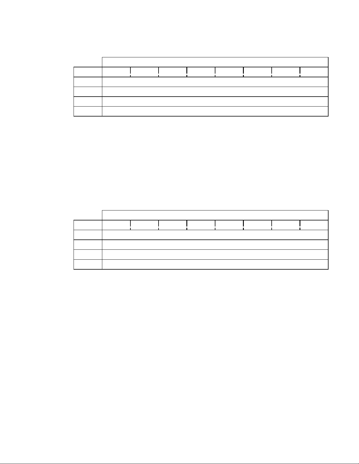
TABLE 2-1A LOGICAL BLOCK ADDRESS FORMAT (TYPE = 00B)
Bit
Byte 7 6 5 4 3 2 1 0
2 Logical Block Address (MSB)
3 Logical Block Address
4 Logical Block Address
5 Logical Block Address (LSB)

Audio Scan (1)
- 13 -
2.1 Audio Scan (1) (CDh)
When AUDIO SCAN (1) is executed, the drive begins a high-speed scan from the Scan Start
Address. The drive plays a block as it crosses each track. Each scan is approximately 15 seconds.
When the specified search address is found, GOOD status is returned.
If the drive is not ready or if the Scan Start Address is not on an audio track, Check Condition
status is returned.
During an audio scan, the drive can receive and execute the following SCSI commands without
scan termination:
AUDIO PLAY (StpAdr=1), AUDIO STATUS, AUDIO STOP
INQUIRY
MODE SELECT, MODE SENSE
READ BUFFER, WRITE BUFFER
READ CD-ROM CAPACITY, READ SUB CHANNEL, READ TOC
RECEIVE DIAGNOSTIC RESULTS, REQUEST SENSE, TEST UNIT READY
RELEASE, RESERVE
There are several commands that when received by the drive during an audio scan, the drive will
terminate the scan and execute the received command. The commands are:
PLAY AUDIO (StpAdr=0), AUDIO SCAN, PLAY AUDIO TRACK
PAUSE/RESUME
READ, SEEK, VERIFY
READ HEADER
START/STOP UNIT, REZERO UNIT
SEND DIAGNSTICS
PREVENT/ALLOW MEDIA REMOVAL
Operation Code is (CDh).
Direct
is “0” (FALSE) when the drive scans forward.
is “1” (TRUE) when the drive scans backwards.
Scan Start Address contains the address at which the audio scan is to begin.
CD-ROM SCSI-2 COMMAND REFERENCE MANUAL VERSION 3.1 (OB-U0077C)
- 14 -
TABLE 2-1B AMIN, ASEC AND AFRAME ADDRESS FORMAT (TYPE = 01B)
Bit
Byte 7 6 5 4 3 2 1 0
2 Reserved
3 CD absolute time (AMIN)
4 CD absolute time (ASEC)
5 CD absolute time (AFRAME)
AMIN, ASEC and AFRAME show the absolute time for the beginning of the disc in BCD. The
values must be in the ranges 0~99 (AMIN), 0~59 (ASEC) and 0~74 (AFRAME).
T
ABLE 2-1C TRACK NUMBER ADDRESS FORMAT (TYPE = 10B)
Bit
Byte 7 6 5 4 3 2 1 0
2 Reserved
3 Reserved
4 Reserved
5 Track number (TNO) (01-99)

Audio Scan (1)
- 15 -
Type defines the format of the Scan Start address field. Type has four parameters.
The four (4) parameters are
00b : Logical Block Address format (reference Table 2-1A)
01b : AMIN, ASEC and AFRAME format (reference Table 2-1B)
10b : Track Number Address format (reference Table 2-1C)
11b : Reserved

CD-ROM SCSI-2 COMMAND REFERENCE MANUAL VERSION 3.1 (OB-U0077C)
- 16 -
TABLE 2-2 AUDIO SCAN (2)
Bit
Byte 7 6 5 4 3 2 1 0
0 Operation Code (BAh)
1 Reserved Direct Reserved
2 Scan Starting Address (MSB)
3 Scan Starting Address
4 Scan Starting Address
5 Scan Starting Address (LSB)
6 Reserved
7 Reserved
8 Reserved
9 Type Reserved
10 Reserved
11 Reserved

Audio Scan (2)
- 17 -
2.2 Audio Scan (2) (BAh)
Operation Code is (BAh).
Direct
If “0” (FALSE), the drive scans forward.
If “1” (TRUE), the drive scans backwards.
Scan Start Address is the address at which the audio scan begins operation.
Type defines the format of the Scan Start address field. Type has four parameters.
The four (4) parameters are
00b : Logical Block Address format (reference Table 2-1A)
01b : AMIN, ASEC and AFRAME format (reference Table 2-1B)
10b : Track Number Address format (reference Table 2-1C)
11b : Reserved
 Loading...