


Pioneer V2500NE, RM-V2400NE, RM-V2400, V2500NA, RMF-V4011 User Manual
... TECHNICAL MANUAL (Ver.1.0)
MULTI PROJECTION UNIT
RM-V2400NA /V2500NA
RM-V2400NE / V2500NE
PROJECTION SCREEN KIT
RMS-V4011/V5011
PROJECTION FRAME
RMF-V4011/V5011
PROJECTION CABINET
RMF-V4011R/V4011CR
Caution
This symbol refers to a hazard or unsafe
practice which can result in personal injury
or property damage.
Notes:
•Pioneer will not be liable for any loss caused by defects of the parts supplied other than by Pioneer.
•An damage during shipping will be compensated for only in the case where Pioneer's specific packing materials for shipping are used.
•The guarantee of performance is applicable only when the assembly and adjustment described in this technical manual and the adjustment described by the system manual of RM-V2000 have been carried out.
•Specifications and design subject to possible modification without notice, due to improvements.
R
1

PIONEER RM-V2400 / 2500
MANUAL.
This Acrobat (IE: a PDF file) version of the Pioneer RM-V2400 / 2500 manual was made from the original digital document and scanning an existing manual. Because of this, there are many less then perfect pages and hand written comments.
As Pioneer is constantly working towards providing the best possible documentation for our products, there may be an improved version of this document available. Please contact your Pioneer representative for additional information.
Josh Kairoff
Pioneer New Media Technology.
October 27, 1997.

CONTENTS
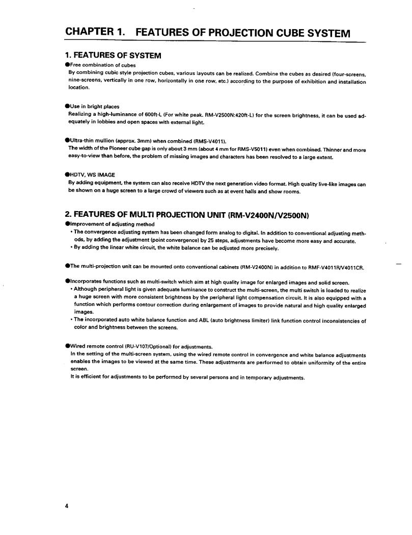
CHAPTER 1. FEATURES OF PROJECTION CUBE SYSTEM .............................................................. |
4 |
|
1. FEATURES OF SYSTEM ........................................................................................................................................... |
4 |
|
2. FEATURES OF MULTI PROJECTION UNIT (RM-V2400N/V2500N) ....................................................................... |
4 |
|
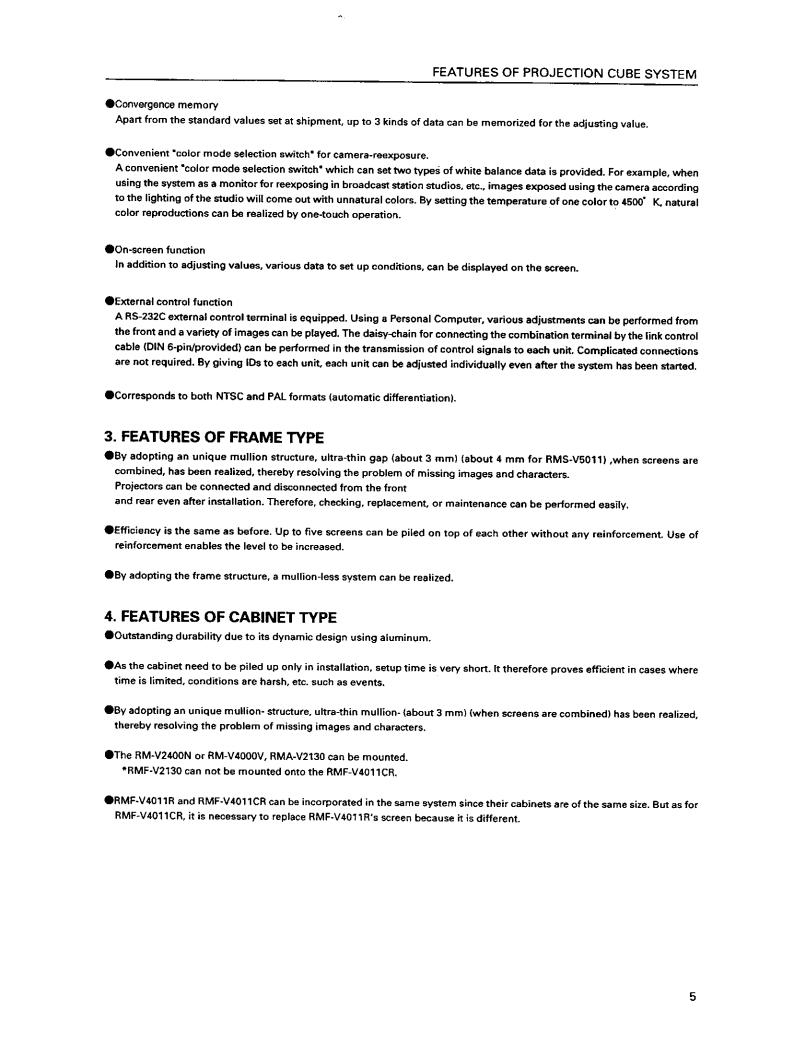
3. FEATURES OF FRAME TYPE ................................................................................................................................... |
5 |
|
4. FEATURES OF CABINET TYPE ................................................................................................................................ |
5 |
|
CHAPTER 2 . GENERAL SPECIFICATIONS ......................................................................................... |
6 |
|
1. SPECIFICATIONS ...................................................................................................................................................... |
6 |
|
(1) |
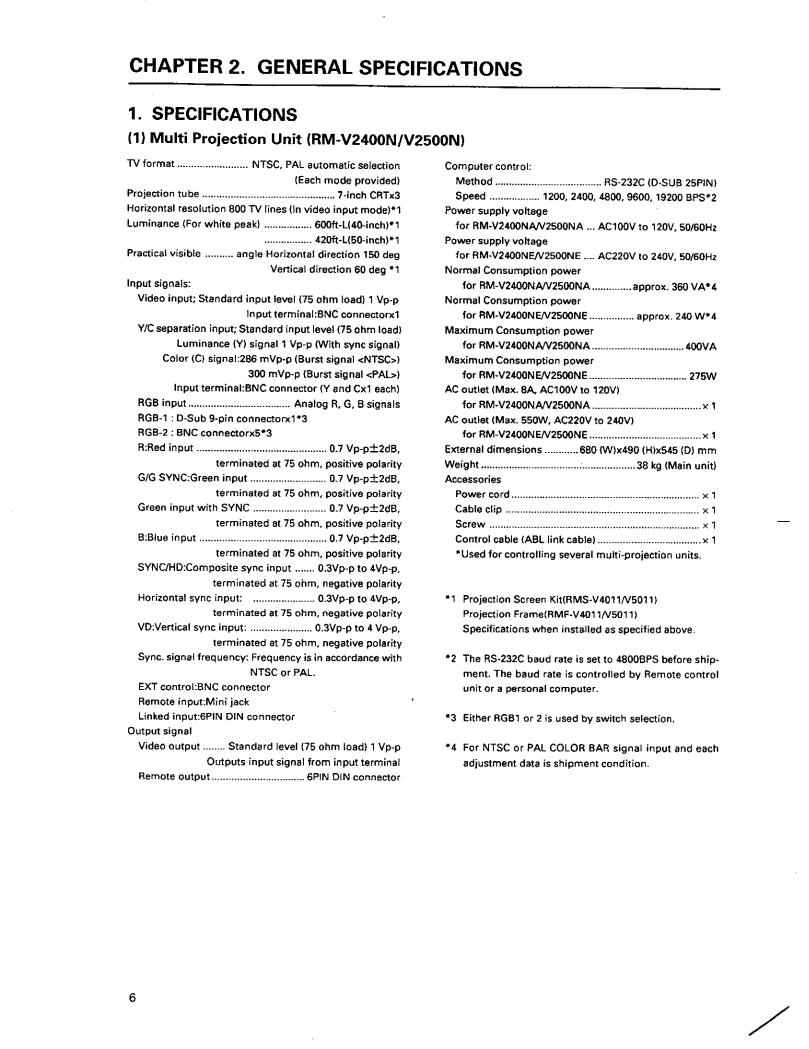
Multi Projection Unit (RM-V2400N/V2500N) ................................................................................................... |
6 |
(2) |
Projection Screen Kit(RMS-V4011/V5011)Product Weight:11.0kg/14.0kg .................................................. |
13 |
(3) |
Projection Frame (RMF-V4011/V5011)Product Weight:26.8kg/28.8kg ........................................................ |
14 |
(4) |
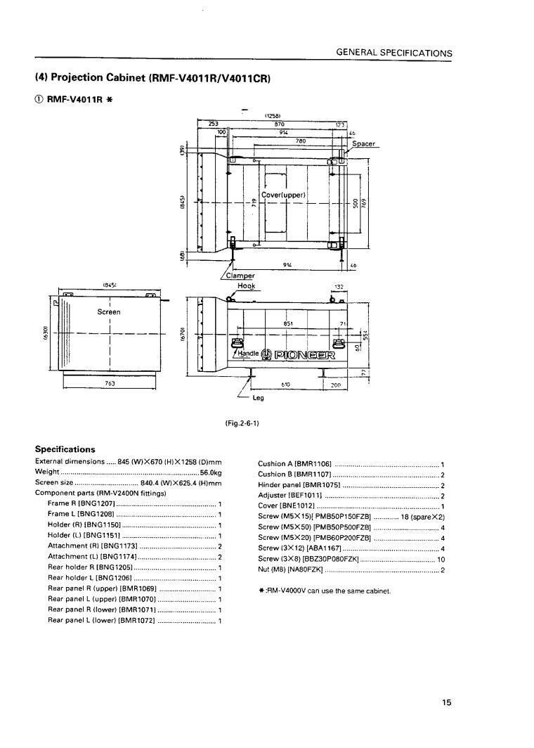
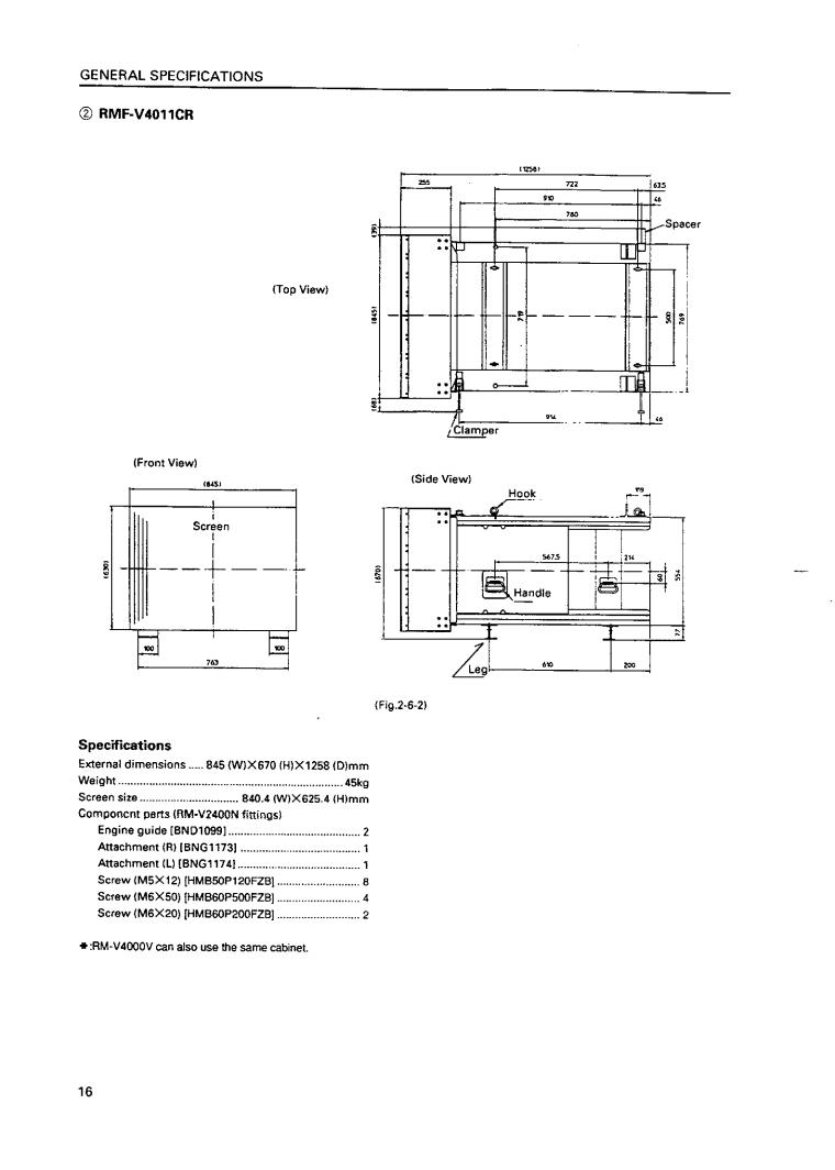
Projection Cabinet(RMF-V4011R/V4011CR) .................................................................................................. |
15 |
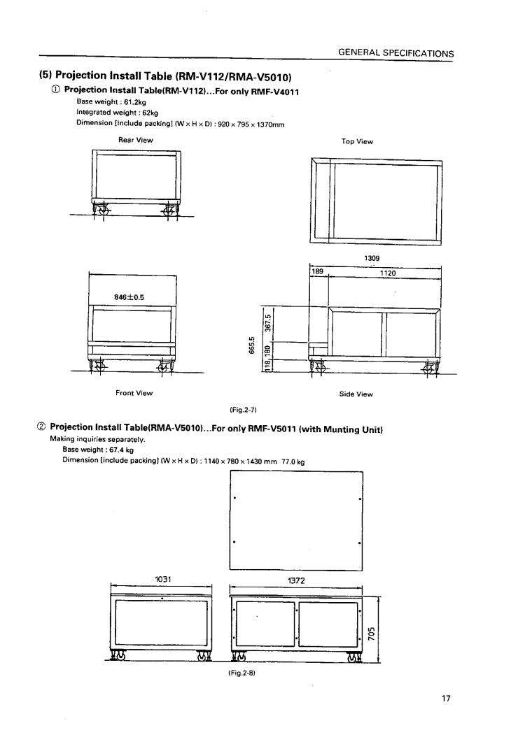
(5) |
Projection Install Table (RM-V112/RMA-V5010) ........................................................................................... |
17 |
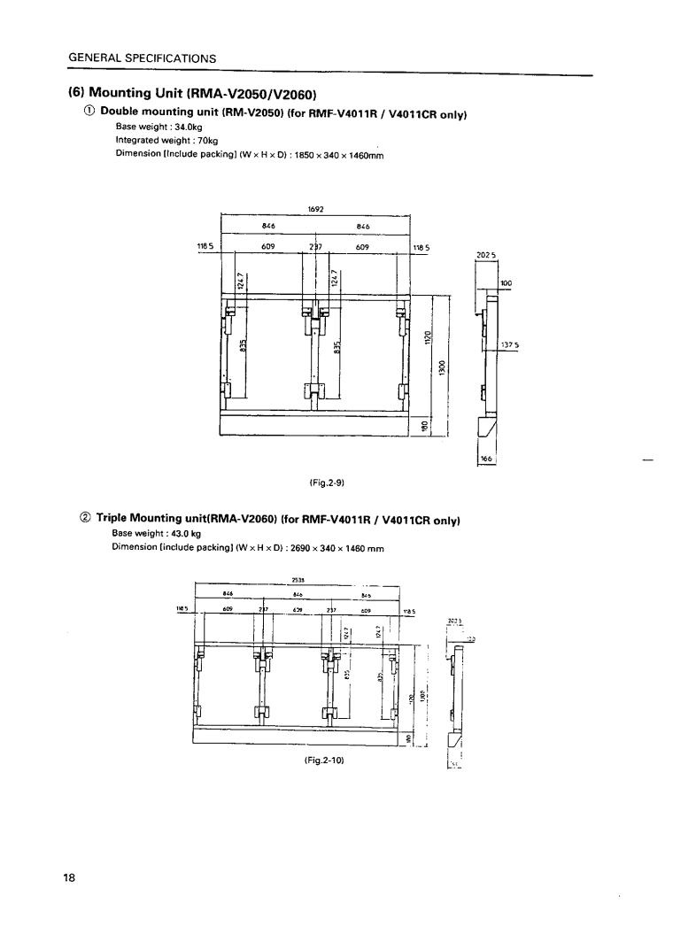
(6) |
Munting Unit (RMA-V2050/2060) ................................................................................................................... |
18 |
(7) |
Multi Video Processor(RMD-V3216/3109,RMD-V2170) ................................................................................ |
19 |
(8) |
Adjustment Control Unit (RU-V107)*Option ................................................................................................ |
21 |
(9) |
Projection Cabinet (RMF-V4011R) Accessories ............................................................................................ |
22 |
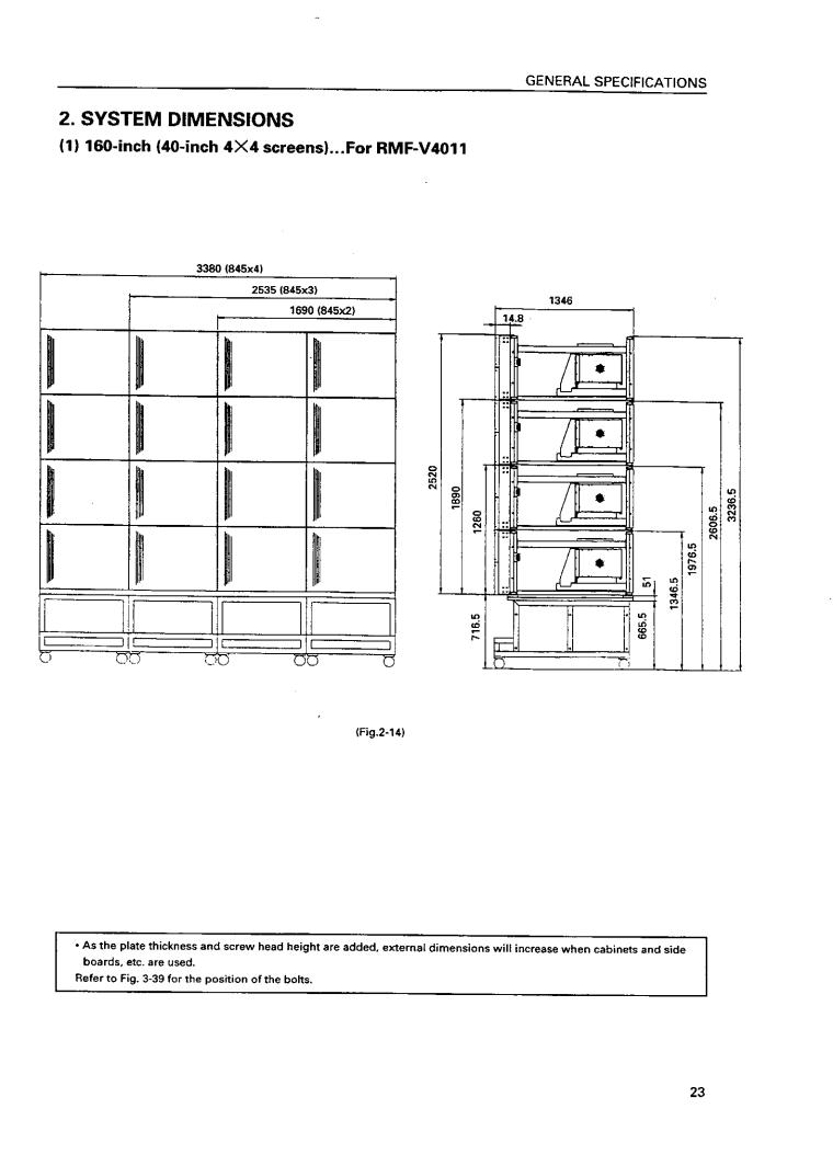
2. SYSTEM DIMENSIONS .......................................................................................................................................... |
23 |
|
(1) |
160-inch (40-inch 4×4screens)…For RMF-V4011 ......................................................................................... |
23 |
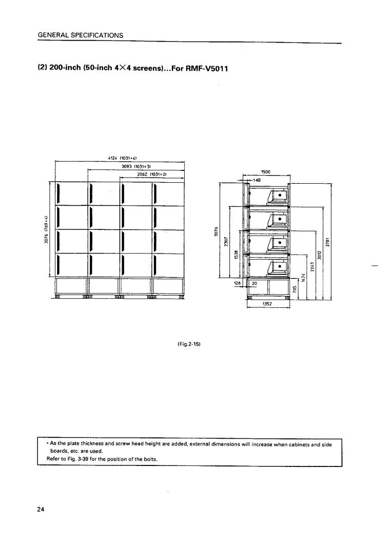
(2) |
200-inch (50-inch 4×4screens)…For RMF-V5011 ......................................................................................... |
24 |
(3) |
160-inch (40-inch 4×4 screens)…For RMF-V4011R ...................................................................................... |
25 |
CHAPTER 3. INSTALLATION AND ASSEMBLY ............................................................................... |
26 |
|
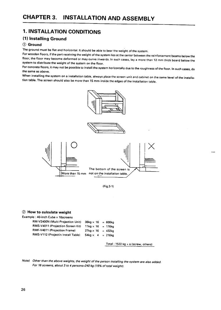
1. INSTALLATION CONDITIONS ............................................................................................................................... |
26 |
|
(1) |
Installing Ground ............................................................................................................................................ |
26 |
(2) |
Ceiling .............................................................................................................................................................. |
27 |
(3) |
Front Space ..................................................................................................................................................... |
27 |
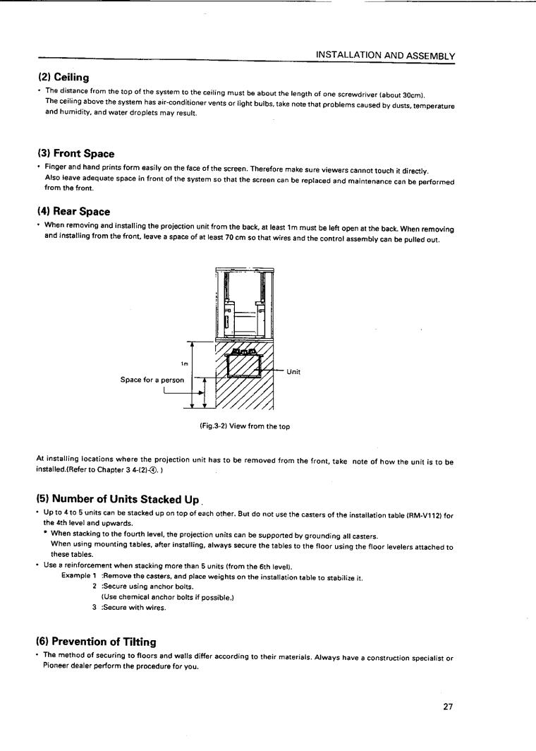
(4) |
Rear Space ...................................................................................................................................................... |
27 |
(5) |
Number of Units Stacked Up ......................................................................................................................... |
27 |
(6) |
Prevention of Tilting ....................................................................................................................................... |
27 |
(7) |
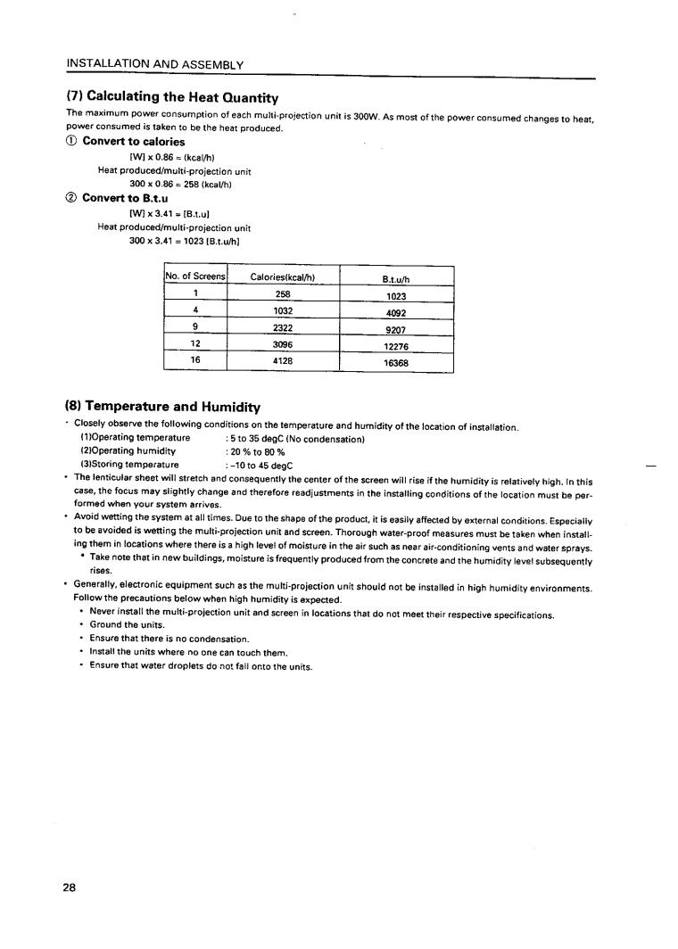
Calculating the Heat Quantity ........................................................................................................................ |
28 |
(8) |
Temperature and Humidity ............................................................................................................................ |
28 |
(9) |
Ventilation for system .................................................................................................................................... |
29 |
(10) Condensation ................................................................................................................................................ |
30 |
|
(11) Visible Angle ................................................................................................................................................. |
31 |
|
(12) Lighting .......................................................................................................................................................... |
34 |
|
(13) Effects of Earth Magnetism .......................................................................................................................... |
34 |
|
(14) Connection with a Power Supply ................................................................................................................ |
35 |
|
(15) Cables Used .................................................................................................................................................. |
36 |
|
(16) Semi-outdoor Installation ............................................................................................................................ |
36 |
|
(17) Precautions for Use of User-Obtained Parts .............................................................................................. |
36 |
|
2. INSTALLATION AND ASSEMBLY ......................................................................................................................... |
37 |
|
(1) |
Confirmation ................................................................................................................................................... |
37 |
(2) |
Opening the Packaging .................................................................................................................................. |
37 |
(3) |
Carrying the Units After Opening Packaging ............................................................................................... |
43 |
3. PRECAUTIONS FOR TRANSPORTATION ............................................................................................................. |
44 |
|
4. ASSEMBLING THE SYSTEM ................................................................................................................................. |
45 |
|
(1) |
Assembling the Projection Frame (RMF-V4011/V5011) ............................................................................... |
45 |
(2) |
Assembling the System ................................................................................................................................. |
46 |
5. SPECIAL INSTALLATION ....................................................................................................................................... |
60 |
|
(1) |
Wall inset ......................................................................................................................................................... |
60 |
(2) |
Diagonal installation ....................................................................................................................................... |
60 |
(3) |
Architrave processing .................................................................................................................................... |
60 |
(4) |
Upside down installation ............................................................................................................................... |
60 |
(5) |
Hanging from ceiling ...................................................................................................................................... |
60 |
CHAPTER 4. ADJUSTMENTS ............................................................................................................ |
61 |
|
1. ADJUSTMENT PREPARATIONS ........................................................................................................................... |
61 |
|
(1) |
Wiring .............................................................................................................................................................. |
61 |
(2) |
Wiring Handling .............................................................................................................................................. |
61 |
(3) |
Aging ............................................................................................................................................................... |
61 |
2

GENERAL SPECIFICATIONS
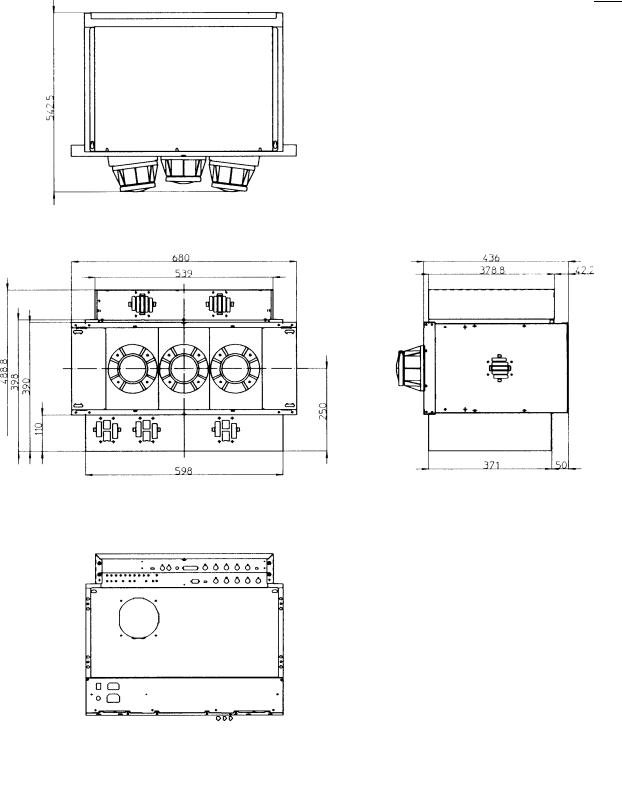
Dimensions
545
|
|
|
|
|
|
|
|
|
|
|
|
|
|
|
|
540 |
|
380 |
|
40 |
|
|
|
|
|||
|
|
|
||||
|
|
|
|
|
|
|
490
(Fig.2-1)
7
GENERAL SPECIFICATIONS
Power Supply Panel
3 |
1 |
3 |
1 |
|
|
|
|
|
|||||||||
|
|
|
|
|
|
|
|
|
|
|
|
|
|
|
|
|
|
|
|
|
|
RM-V2400NA/V2500NA |
|
|
|
|
|
|
|
RM-V2400NE/V2500NE |
|
|
|
|
|
|
|
|
|
|
|
|
|
|
|
|
|
|
|
|
|||
|
|
|
|
|
|
|
|
|
|
|
|
|
|
|
|
|
|
|
|
|
|
|
|
|
|
|
|
|
|
|
|
|
|
|
|
|
|
|
|
|
|
|
|
|
|
|
|
|
|
|
|
|
|
|
|
|
|
|
|
|
|
|
|
|
|
|
|
|
|
|
|
|
|
|
|
|
|
|
|
|
|
|
|
|
|
|
|
|
|
|
|
|
|
|
|
|
|
|
|
|
|
|
|
|
|
|
|
|
4 |
2 |
4 |
2 |
||
|
|
|
|
|||
|
|
|
|
(Fig. 2-2) |
|
|
|
|
|
|
|
|
|
No. |
Name |
|
Type |
|
Function |
|
|
|
|
|
|
||
1 |
AC inlet |
|
Connects AC power cord. |
|
||
|
|
|
|
|
||
|
|
|
|
Connects other multi-projection units. Not linked to main power |
||
2 |
AC outlet |
|
switch. Note 1) |
|
||
|
|
|
|
|
||
3 |
Main power switch |
See-saw switch |
Turns on and off the power supplied to the main unit. Sets into |
|||
the standby state when turned on. |
||||||
|
|
|
|
|||
4 |
Fuse holder |
|
Storesthefuse.No-oneexceptservicemanshouldtouchthispart. |
|||
|
|
|
|
|
|
|
Note 1) Refer to page 35 [(14) Connection with a power supply 3 Connection].
Control Panel
(Fig. 2-3)
8

|
|
|
|
|
GENERAL SPECIFICATIONS |
|
|
|
|
|
|
|
|
No. |
Name |
Type |
|
|
Function |
|
|
|
|
|
|
||
1 |
ABL link switch |
Slide switch |
Used for switching the control level of the ABL link control voltage |
|||
|
|
|
when ABL link is ON. |
|
||
|
|
|
|
|
||
2 |
Linked input terminal |
DIN 6PIN |
Input terminal of ABL signal, remote control signal and RS-232C |
|||
|
|
|
signal |
|
|
|
|
|
|
|
|
||
3 |
Linked output terminal |
DIN 6PIN |
Output terminal of ABL signal, remote control signal, and RS-232C |
|||
|
|
|
signal |
|
|
|
|
|
|
|
|
||
4 |
Remote control connection ter- |
Mini jack |
Connectedtoadjustingremotecontrol(optional) |
|||
|
minal |
|
|
|
|
|
|
|
|
|
|
|
|
5 |
RS-232C port |
D-sub 25 PIN (Female) |
RS-232Ccommunicationconnector |
|
||
|
|
|
|
|
||
6 |
Control input terminal |
BNC connector |
Video input and Y/C input external switching control signal input |
|||
|
|
|
terminal |
|
Normal(videosignalinput):Open |
|
|
|
|
|
|
SelectY/Cinput |
: Low(0V) |
|
|
|
|
|
|
|
|
|
|
|
|
||
7 |
Y (Luminance) input terminal |
BNC connector |
Luminancesignalinputterminal |
|
||
|
|
|
|
|
||
8 |
C (Color) input terminal |
BNC connector |
Colorsignalinputterminal |
|
||
|
|
|
|
|
||
9 |
Video input terminal |
BNC connector |
Videosignalinputterminal |
|
||
|
|
|
|
|||
0 |
Video output terminal |
BNC connector |
Videoinputterminal9through-outterminal |
|||
|
|
|
|
|||
- |
TERMINATE switch |
Slide switch |
Turns on when terminates the video input terminal 9at 75 ohm |
|||
|
|
|
|
|
||
= |
COMBINATION switch |
Tact switch |
Turns on when linked to ABL |
|
||
|
|
|
|
|
||
~ |
MULTI switch |
Tact switch |
Turns on when used on multi screen |
|
||
|
|
|
|
|||
! |
COLOR MODE switch |
Tact switch |
Switchesthecolortemperature.1:Normaluse.2:Re-exposure |
|||
|
|
|
|
|||
@ |
INPUT switch |
Tact switch |
SwitchesVIDEOinput,Y/Cinput,RGBinput. |
|||
|
|
|
SwitchesVIDEOinputandY/Cinputwiththeexternalcontrolsignal |
|||
|
|
|
6at VIDEO position |
|
||
|
|
|
|
|||
# |
POWER switch |
Tact switch |
Power OFF : STANDBY (Red LED) lights up |
|||
|
|
|
Power ON : ON (Green LED) lights up |
|
||
|
|
|
|
|||
$ |
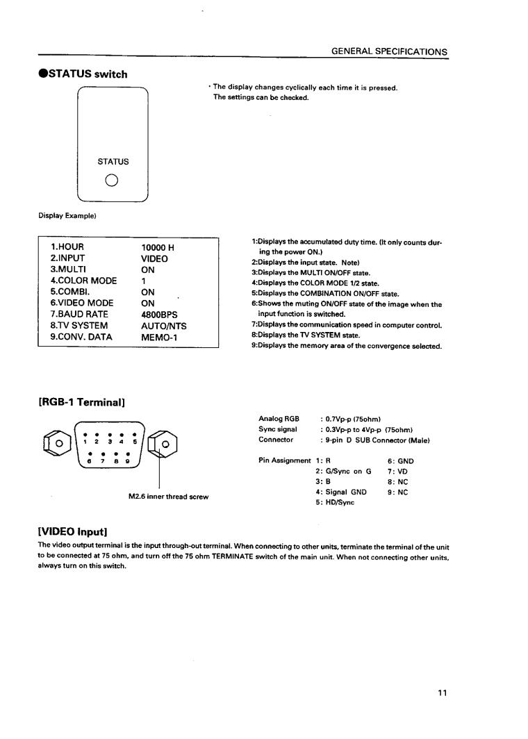
STATUS switch |
Tact switch |
Accumulated duty time: * Switch which displays setting states of |
|||
|
|
|
each switch on the screen. |
|
||
|
|
|
|
|
||
% |
RGB input terminal |
D-sub 9PIN (Male) |
RGBsignalinputterminal |
|
||
|
|
|
|
|
||
^ |
RGB input select switch |
Slide switch |
SwitchesRGBsignalinputterminaltype |
|
||
|
|
|
|
|
||
& |
RGBinputterminal(Verticalsync) |
BNC connector |
RGBsignalverticalsyncinputterminal |
|
||
|
|
|
|
|||
* |
RGB input terminal |
BNC connector |
RGB signal horizontal sync and composite sync (Only for input sig- |
|||
|
(Horizontal sync/composite |
|
nal H/V sync) input terminal |
|
||
|
sync) |
|
|
|
|
|
|
|
|
|
|
||
( |
RGB input terminal (B) |
BNC connector |
RGB signal B input terminal |
|
||
|
|
|
|
|||
) |
RGB input terminal |
BNC connector |
RGB signal G and composite sync (Input signal G on sync) input |
|||
|
(G/composite sync) |
|
terminal |
|
|
|
|
|
|
|
|
||
_ |
RGB input terminal (R) |
BNC connector |
RGB signal R input terminal |
|
||
|
|
|
|
|
|
|
•To turn off the power, use the POWER switch - of the unit, the RS-232C control, or wired remote control (optional). (If turned off using the main POWER switch or by disconnecting the power cable from the outlet, the settings of the above = to @ switches and the state of the TV SYSTEM and convergence memory will not be recorded on the memory.)
Consequently when starting up or stopping the whole system by AC ON/OFF in setup conditions for a demonstration, it is necessary to turn off the power using the above method to record each setting in the memory.
(Refer to "CHAPTER 4. ADJUSTMENTS, (5)Equipment Required for Adjustments".)
*: Accumulated duty time
Counts only when the power is ON.
9
GENERAL SPECIFICATIONS
(2) Projection Screen Kit (RMS-V4011/V5011) Product Weight : 11.0 kg/14.0kg
845 |
148 |
(1031) |
(148) |
630
(769)
(Fig.2-4)
Unit:mm
The number in parentheses is the dimentsion for RMS-V5011
Accessory
Screw rivet ........................................................................................................................... |
6 |
13

GENERAL SPECIFICATIONS
(3) Projection Frame (RMF-V4011/V5011) Product Weight : 26.8kg/28.8kg
1201(1352)
845(1031)
630 |
(769) |
|
(Fig.2-5) |
|
Unit:mm |
|
The number in parentheses is |
|
the dimension for RMS-V5011 |
Accessories |
|
Metal fixture (R) ................................................................................................................... |
1 |
Metal fixture (L) ................................................................................................................... |
1 |
Stopper ................................................................................................................................. |
2 |
Screw M5x10 ................................................................................................................. |
38+2 |
Screw M5x35 ....................................................................................................................... |
6 |
Screw M5x50 ....................................................................................................................... |
4 |
Hexagon head bolt (with washer) M8x45 .......................................................................... |
8 |
Shield .................................................................................................................................... |
1 |
Rivet ...................................................................................................................................... |
2 |
14
GENERAL SPECIFICATIONS
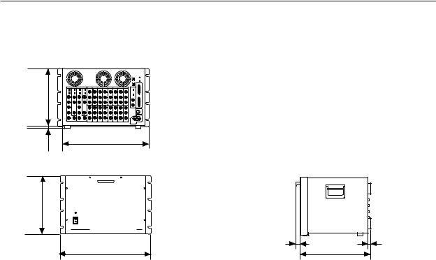
(7) Multi Video Processor (RMD-V3216/V3109, RMD-V2170)
1Multi Video Processor (RMD-V3216/V3109)
Rear View
299
15
0 |
0 |
430
D
314
POWER
ON
OFF
MULTI VIDEO PROCESSOR RMD-V3216 |
|
16 |
19 |
482.6 |
420 |
Front View |
Side View |
(Fig.2-11)
Main Specifications of Multi Video Processor
(RMD-V3216/V3109) Input signal
Input video signal (Can be expanded up to four systems)
2-line (RMD-V3216), 1-line (RMD-V3109) .... BNC terminal |
|
1 Composite video signal |
........................................... |
....................................... 1.0 Vp-p (75ohm terminated) |
|
2Y/C separation signal |
|
Y (With sync) ................................ |
1.0Vp-p (75ohm) |
C burst level ............................ |
0.286 Vp-p (75ohm) |
*1 or 2 signal format can be selected |
|
*Only 1 has a terminate switch, throughout |
|
Input standard sync signal .......................... |
BNC terminal |
1 Composite sync signal ................ |
0.286 to 4.0 Vp-p |
2 Composite video signal |
|
Video level ...................... |
0 to 0.714 Vp-p (75ohm) |
Single level ............................. |
0.286 Vp-p (75ohm) |
*Terminate switch, throughout |
|
RS-232C control input 25-pin D-SUB |
|
Output signal
Output video signal |
|
|
16-line (RMD-V3216), 9-line (RMD-V3109) ... |
BNC terminal |
|
1 Composite sync signal ................ |
1.0 |
Vp-p (75ohm) |
2 Y/C separation signal |
|
|
Y (With sync) ................................. |
1.0Vp-p (75ohm) |
|
C (With burst) Burst level ....... |
0.286 |
Vp-p (75ohm) |
*1 and 2 signal formats are output simultaneously.
3RGB signal |
|
Green (Sync on Green) |
............................... 1.0 Vp-p |
SYNC ........................................................... |
0.3 Vp-p |
B.R ................................................................ |
0.7 Vp-p |
Output reference composite sync signal BNC terminal |
|
TTL level |
|
(Or input reference sync signal throughout) |
|
Others |
|
Power supply .............................. |
AC100 to 120V (50/60 Hz) |
Power consumption ............................................................. |
|
............................ (RMD-V3216, RMD-V3109) 350W, 700VA |
|
Operating temperature and humidity ......................range |
|
........................................................................... |
5 °C to 35 °C |
Below 85% (No condensation) |
|
External dimensions (RMD-V3216, ...............RMD-V3109) |
|
................... 482.6 (Width)x420 (Depth)x314 (Height) (mm) |
|
|
(Excluding handle) |
Weight |
|
RMD-V3216 ............................................................... |
22.5 kg |
RMD-V3109 ............................................................... |
22.0 kg |
Accessories |
|
Rack mounting screw M5 .................................................. |
8 |
Rack mounting washer ...................................................... |
8 |
19
GENERAL SPECIFICATIONS
2Multi Video Processor (RMD-V2170)
Front View |
Side View |
|
Rear View
(Fig.2-12)
Main Specifications of Multi Video Processor (RMD-V2170)
Input video signal |
......................................... |
NTSC format |
Input signal band ...................................... |
|
Above 4.2 MHz |
Input |
|
|
Video input |
|
|
Input signal .............................................................. |
|
|
..................... |
NTSC composite video signal (BNC) |
|
Input system ................................................... |
4-line |
|
Standard input ....................level |
1Vp-p (75 load) |
|
Y/C separation |
|
|
Input signal .... |
NTSC Y/C separation signal (BNC) |
|
Input system ................................................... |
4-line |
|
Standard input ...............level |
Y:1 Vp-p (75 load) |
|
.................... |
C:286 mVp - p (75 load burst signal) |
|
*The video input or Y/C separation input is to be |
||
selected by the switch on the rear panel. |
||
Reference sync signal input |
||
Input signal ............................. |
|
Composite sync (BNC) |
Standard input .....................................................level |
|
|
...................................... |
|
Composite sync 0.3 to 4 Vp-p |
Control input |
|
|
Input signal .... |
Conforms to RS - 232C (25-pin, D-sub) |
|
Output
Video output
Output signal ............................................................
...................... NTSC composite video signal (BNC)
Output system ............................................... |
|
16-line |
Standard output level |
.................. 1Vp-p (75 load) |
|
Y/C separation output |
|
|
Output signal ... |
NTSC Y/C separation signal (BNC) |
|
Output system ............................................... |
|
16-line |
Standard output level ............... |
Y1 Vp-p (75 load) |
|
...................... C286 mVp-p (75 load, burst signal) |
||
Test signal output |
|
|
Output signal ................................................................. |
|
|
............................ NTSC composite video signal (BNC) |
||
Standard output level ....................... |
1Vp-p (75 load) |
|
Sync signal output............................... |
|
TTL level (BNC) |
Power supply voltage ...................... |
|
100 to 120V, 50/60 Hz |
Power consumption ....................................... |
|
300W/500VA |
External dimensions ............ |
483 (W)x314 (H)x469 (D) mm |
|
Weight .......................................................................... |
|
33 kg |
*Line up series of RMD-V2110 with 9 OUTPUT CIRCUITS.
20
GENERAL SPECIFICATIONS
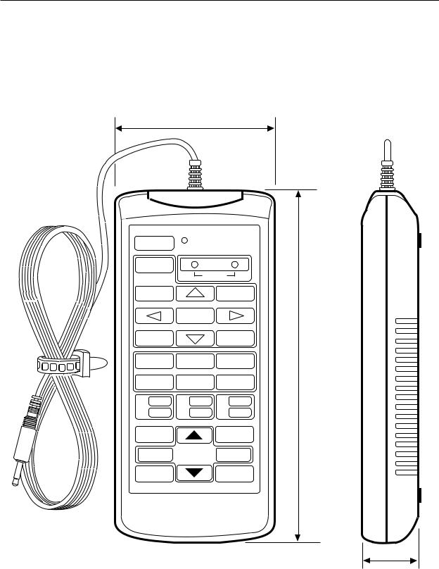
(8) Adjustment Control Unit (RU-V107)*Option
84
POWER Dë
ADJUSTMENT CONTROL UNIT RU-V107
0
|
ADJ IN |
|
1 |
2 |
3 |
4 |
5 |
6 |
7 |
8 |
9 |
A |
B |
C |
D |
E |
F |
R ADJ |
G ADJ |
B ADJ |
ON/OFF |
ON/OFF |
ON/OFF |
INPUT SEL |
|
MAIN MENU |
2/– |
|
+/3 |
187
DISP CALL |
ADJ OUT |
Cable length : 5m
29
(Fig.2-13)
Accessories |
|
AA dry battery (IEC R6P) ...................................................................................................... |
2 |
Cable (5m) ............................................................................................................................ |
3 |
21

GENERAL SPECIFICATIONS
(9) Projection Cabinet (RMF-V4011R) Accessories
To attach the multi-projection unit (RM-V2400N) to the conventional RM-V2000A, the RMF-V4011R accessories (metal fixtures) are required. The following lists the required parts. For details of attaching the multi-projection unit, refer to Chapter 3. "4-(2)Assembling the System".
Frame R (BNG1207) ....................................................................................................... |
1 |
Frame L (BNG1208) ....................................................................................................... |
1 |
Holder (R) (BNG1150) .................................................................................................... |
1 |
Holder (L) (BNG1151) .................................................................................................... |
1 |
Attachment (R) (BNG1173) ............................................................................................ |
2 |
Attachment (L) (BNG1174) ............................................................................................ |
2 |
Rear holder R (BNG1205) .............................................................................................. |
1 |
Rear holder L (BNG1206) .............................................................................................. |
1 |
Rear panel R (upper) (BMR1069) .................................................................................. |
1 |
Rear panel L (upper) (BMR1070) .................................................................................. |
1 |
Rear panel R (lower) (BMR1071) .................................................................................. |
1 |
Rear panel L (lower) (BMR1072) ................................................................................... |
1 |
Cushion A (BMR1106) ................................................................................................... |
1 |
Cushion B (BMR1107) .................................................................................................... |
2 |
Hinder panel (BMR1075) ............................................................................................... |
2 |
Adjuster (BEF1011) ........................................................................................................ |
2 |
Screw (M5x15) (PMB50P150FZB) ............................................................... |
18 (Spare 2) |
Screw (M5x50) (PMB50P500FZB) ................................................................................. |
4 |
Screw (M6x20) (PMB60P200FZB) ................................................................................. |
4 |
Screw (3x12) (ABA1167) ................................................................................................ |
4 |
Screw (3x8) (BBZ30P080FZK) ..................................................................................... |
10 |
Nut (M8) (NA80FZK) ...................................................................................................... |
2 |
Note : RM-V4000V can assemble with the same accessories.
22

INSTALLATION AND ASSEMBLY
(9) Ventilation for system
The ventilation method differs according to where the system is installed. The following shows how to provide ventilation for the units according to the place of installation. Refer to these and keep the installation condition in the previous section [(8) Temperature and Humidity] at the system.
But when installing your unit, consult your dealer.
1When there are no walls on all sides (within 1m)
As shown in Fig. 3-3, attach the top panel, side panel, and rear panel.
(Note)
When attaching the rear panel, be careful not to block the vents for the fan of the projection unit.
2When there is a wall at the back *
As shown in Fig. 3-5, mount a large fan to the top panel, provide vents for inhaling air at the bottom panel to blow out air inside. Always leave more than 300 mm between the wall and the back of the unit.
(Fig. 3-3) |
(Fig. 3-5) |
3When blocking the bottom (when placing the projection unit on the floor directly) * Same as 1. (Fig. 3-6)
|
<Note> |
|
*: There should be no obstacles within the 1m area of the |
|
unit except for the rear and bottom. If this condition is |
|
not followed, construct your own ventilation system |
|
(large fan, low temperature by air-conditioning, etc.) |
(Fig. 3-6) |
according to the site of use. |
29
 Loading...