


RCS-LX60D
SX-LX60D SSP-LX60D DVR-LX60D
Audio Multi-channel Receiver Subwoofer
Speaker System
HDD/DVD Recorder
®
 ®
®
Discover the benefits of registering your product online at
http://www.pioneer.co.uk (or http://www.pioneer.eu)
Operating Instructions

Thank you for buying this Pioneer product.
Please read through these operating instructions so that you will know how to operate your model properly. After you have finished reading the instructions, put them in a safe place for future reference.
IMPORTANT
The lightning flash with arrowhead symbol, within an equilateral triangle, is intended to alert the user to the presence of uninsulated "dangerous voltage" within the product's enclosure that may be of sufficient magnitude to constitute a risk of electric shock to persons.
The exclamation point within an equilateral triangle is intended to alert the user to the presence of important operating and maintenance (servicing) instructions in the literature accompanying the appliance.
WARNING
This equipment is not waterproof. To prevent a fire or shock hazard, do not place any container filed with liquid near this equipment (such as a vase or flower pot) or expose it to dripping, splashing, rain or moisture.
This product complies with the Low Voltage Directive (73/23/EEC, amended by 93/68/EEC), EMC Directives (89/336/EEC, amended by 92/31/EEC and 93/68/EEC).
POWER-CORD CAUTION
Handle the power cord by the plug. Do not pull out the plug by tugging the cord and never touch the power cord when your hands are wet as this could cause a short circuit or electric shock. Do not place the unit, a piece of furniture, etc., on the power cord, or pinch the cord. Never make a knot in the cord or tie it with other cords. The power cords should be routed such that they are not likely to be stepped on. A damaged power cord can cause a fire or give you an electrical shock. Check the power cord once in a while. When you find it damaged, ask your nearest PIONEER authorized service center or your dealer for a replacement.
CAUTION
This product is a class 1 laser product, but this product contains a laser diode higher than Class 1. To ensure continued safety, do not remove any covers or attempt to gain access to the inside of the product. Refer all servicing to qualified personnel.
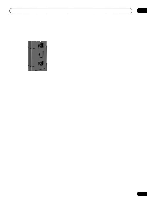
The following caution label appears on your unit. Location: inside of the HDD/DVD Recorder

If the AC plug of this unit does not match the AC outlet you want to use, the plug must be removed and appropriate one fitted. Replacement and mounting of an AC plug on the power supply cord of this unit should be performed only by qualified service personnel. If connected to an AC outlet, the cut-off plug can cause severe electrical shock. Make sure it is properly disposed of after removal.
The equipment should be disconnected by removing the mains plug from the wall socket when left unused for a long period of time (for example, when on vacation).
CAUTION
The STANDBY/ON switch on this unit will not completely shut off all power from the AC outlet. Since the power cord serves as the main disconnect device for the unit, you will need to unplug it from the AC outlet to shut down all power. Therefore, make sure the unit has been installed so that the power cord can be easily unplugged from the AC outlet in case of an accident. To avoid fire hazard, the power cord should also be unplugged from the AC outlet when left unused for a long period of time (for example, when on vacation).
WARNING
To prevent a fire hazard, do not place any naked flame sources (such as a lighted candle) on the equipment.
VENTILATION CAUTION (Receiver subwoofer)
When installing this unit, make sure to leave space around the unit for ventilation to improve heat radiation (at least 5 cm at top, 5 cm at rear, and 5 cm at each side).
VENTILATION CAUTION (HDD/DVD Recorder)
When installing this unit, make sure to leave space around the unit for ventilation to improve heat radiation (at least 10 cm at top, 10 cm at rear, and 10 cm at each side).
WARNING
Slots and openings in the cabinet are provided for ventilation to ensure reliable operation of the product, and to protect it from overheating. To prevent fire hazard, the openings should never be blocked or covered with items (such as newspapers, table-cloths, curtains) or by operating the equipment on thick carpet or a bed.
|
5 cm |
5 cm |
5 cm |
Receiver subwoofer
|
10 cm |
10 cm |
10 cm |
HDD/DVD Recorder
If you want to dispose this product, do not mix it with general household waste. There is a separate collection system for used electronic products in accordance with legislation that requires proper treatment, recovery and recycling.
Private households in the member states of the EU, in Switzerland and Norway may return their used electronic products free of charge to designated collection facilities or to a retailer (if you purchase a similar new one).
For countries not mentioned above, please contact your local authorities for the correct method of disposal.
By doing so you will ensure that your disposed product undergoes the necessary treatment, recovery and recycling and thus prevent potential negative effects on the environment and human health.
Replacement and mounting of an AC plug on the power supply cord of this unit should be performed only by qualified service personnel.
IMPORTANT: THE MOULDED PLUG
This appliance is supplied with a moulded three pin mains plug for your safety and convenience. A 5 amp fuse is fitted in this plug. Should the fuse need to be replaced, please ensure that the replacement fuse has a rating of 5 amps and that it is approved by ASTA or BSI to BS1362.
Check for the ASTA mark |
or the BSI mark |
on the body of the fuse. |
If the plug contains a removable fuse cover, you must ensure that it is refitted when the fuse is replaced. If you lose the fuse cover the plug must not be used until a replacement cover is obtained. A replacement fuse cover can be obtained from your local dealer.
If the fitted moulded plug is unsuitable for your socket outlet, then the fuse shall be removed and the plug cut off and disposed of safely. There is a danger of severe electrical shock if the cut off plug is inserted into any 13 amp socket.
If a new plug is to be fitted, please observe the wiring code as shown below. If in any doubt, please consult a qualified electrician.
IMPORTANT: The wires in this mains lead are coloured in accordance with the following code: Blue : Neutral Brown : Live
As the colours of the wires in the mains lead of this appliance may not correspond with the coloured markings identifying the terminals in your plug, proceed as follows ;
The wire which is coloured BLUE must be connected to the terminal which is marked with the letter N or coloured BLACK.
The wire which is coloured BROWN must be connected to the terminal which is marked with the letter L or coloured RED.
How to replace the fuse: Open the fuse compartment with a screwdriver and replace the fuse.
D3-4-2-1-2-2_B_En

Section One
Contents
Section One
What’s in the box . . . . . . . . . . . . . . . . . . . . . . . . . . . . 5
01 Speaker Setup Guide
Safety precautions when setting up . . . . . . . . . . . . . . 6
Home theater sound setup . . . . . . . . . . . . . . . . . . . . . 6
Front surround setup (recommended) . . . . . . . . . . . 6
Standard surround setup . . . . . . . . . . . . . . . . . . . . . 8
Wall mounting the speakers . . . . . . . . . . . . . . . . . . . . 9
Before mounting . . . . . . . . . . . . . . . . . . . . . . . . . . . 9
Additional notes on speaker placement . . . . . . . . . . . 9
02 Connecting up
Basic connections . . . . . . . . . . . . . . . . . . . . . . . . . . 10
Using this system for TV audio . . . . . . . . . . . . . . . . . 14
03 Controls and displays
Display unit . . . . . . . . . . . . . . . . . . . . . . . . . . . . . . . 15 Display . . . . . . . . . . . . . . . . . . . . . . . . . . . . . . . . . . 15 HDD/DVD Recorder . . . . . . . . . . . . . . . . . . . . . . . . . 16 Display . . . . . . . . . . . . . . . . . . . . . . . . . . . . . . . . . . 17 Common Interface . . . . . . . . . . . . . . . . . . . . . . . . . . 17 Inserting a CA module . . . . . . . . . . . . . . . . . . . . . . 17 Remote control. . . . . . . . . . . . . . . . . . . . . . . . . . . . . 18 Using the remote control . . . . . . . . . . . . . . . . . . . . . 20
Putting the batteries in the remote control . . . . . . . . 21
04 Before you start
Switching on . . . . . . . . . . . . . . . . . . . . . . . . . . . . . . 22 Setting up. . . . . . . . . . . . . . . . . . . . . . . . . . . . . . . . . 22 Basic operation . . . . . . . . . . . . . . . . . . . . . . . . . . . . 23 Watching a DVD . . . . . . . . . . . . . . . . . . . . . . . . . . 23 Listening to a CD . . . . . . . . . . . . . . . . . . . . . . . . . . 23
Watching a title recorded on the HDD . . . . . . . . . . 23
Listening to the radio . . . . . . . . . . . . . . . . . . . . . . . 23
05 Getting started
System demo setting . . . . . . . . . . . . . . . . . . . . . . . . 24
Using the Auto MCACC setup for optimal
surround sound . . . . . . . . . . . . . . . . . . . . . . . . . . . . 24
06 Listening to your system
Auto listening mode . . . . . . . . . . . . . . . . . . . . . . . . . 26
Listening in surround sound. . . . . . . . . . . . . . . . . . . 26 Dolby Pro Logic II Music settings . . . . . . . . . . . . . . 26 Using Front Stage Surround Advance . . . . . . . . . . . 27
Using Advanced Surround . . . . . . . . . . . . . . . . . . . . 27 Listening in stereo . . . . . . . . . . . . . . . . . . . . . . . . . . 27
Using the Sound Retriever . . . . . . . . . . . . . . . . . . . . 27 Listening with Acoustic Calibration EQ. . . . . . . . . . . 28
Enhancing dialogue . . . . . . . . . . . . . . . . . . . . . . . . . 28
Using Quiet and Midnight listening modes . . . . . . . 28
4
Adjusting the bass and treble . . . . . . . . . . . . . . . . . . 28
Boosting the bass level. . . . . . . . . . . . . . . . . . . . . . . 28
07 Listening to the radio
Listening to the radio . . . . . . . . . . . . . . . . . . . . . . . . 29
Improving poor FM reception . . . . . . . . . . . . . . . . . 29
Improving poor AM sound . . . . . . . . . . . . . . . . . . . 29
Changing the noise cut mode . . . . . . . . . . . . . . . . 29
Memorizing stations. . . . . . . . . . . . . . . . . . . . . . . . 30
Listening to station presets . . . . . . . . . . . . . . . . . . 30
Using RDS . . . . . . . . . . . . . . . . . . . . . . . . . . . . . . . . 30
Displaying RDS information. . . . . . . . . . . . . . . . . . 30 Searching for RDS programs . . . . . . . . . . . . . . . . . 30
08 Surround sound settings
Using the Setup menu . . . . . . . . . . . . . . . . . . . . . . . 31 Channel level setting . . . . . . . . . . . . . . . . . . . . . . . 31
Speaker distance setting . . . . . . . . . . . . . . . . . . . . 31
Dynamic Range Control . . . . . . . . . . . . . . . . . . . . . 32 Dual mono setting . . . . . . . . . . . . . . . . . . . . . . . . . 32
Adjusting the channel levels using the test tone. . . . 32
09 Other connections
Connecting auxiliary components . . . . . . . . . . . . . . 33 Connecting an analog audio component . . . . . . . . 33 Listening to an external audio source . . . . . . . . . . . . 33 Connecting external antennas . . . . . . . . . . . . . . . . . 34 Using this unit with a Pioneer plasma display . . . . . 34 SR+ Setup for Pioneer plasma displays. . . . . . . . . 35
Using the SR+ mode with a Pioneer
plasma display . . . . . . . . . . . . . . . . . . . . . . . . . . . . 35
10 Additional information
Dimming the display . . . . . . . . . . . . . . . . . . . . . . . . 36 DTS CD setting . . . . . . . . . . . . . . . . . . . . . . . . . . . . . 36 Setting the sleep timer . . . . . . . . . . . . . . . . . . . . . . . 36 Resetting the system . . . . . . . . . . . . . . . . . . . . . . . . 36
Installation and maintenance . . . . . . . . . . . . . . . . . . 37
Hints on installation . . . . . . . . . . . . . . . . . . . . . . . . 37 Troubleshooting . . . . . . . . . . . . . . . . . . . . . . . . . . . . 37 General . . . . . . . . . . . . . . . . . . . . . . . . . . . . . . . . . 37 Tuner . . . . . . . . . . . . . . . . . . . . . . . . . . . . . . . . . . . 38 Error Messages . . . . . . . . . . . . . . . . . . . . . . . . . . . 38 Glossary . . . . . . . . . . . . . . . . . . . . . . . . . . . . . . . . . . 39 Specifications. . . . . . . . . . . . . . . . . . . . . . . . . . . . . . 39
Section Two
Operating instructions for HDD/DVD Recorder (DVR-LX60D) . . . . . . . . . . . . . . 40
En

Section One
What’s in the box
Please confirm that the following items are all supplied.
Receiver subwoofer (SX-LX60D) box:
•Remote control (page 18)
•AA/R6 dry cell batteries (to confirm operation) x2 (page 21)
•Display unit (page 15)
•Power cord (page 12)
•AM loop antenna (page 10)
•FM wire antenna (page 10)
•Control cable (page 10)
•Display cable (page 10)
•Coaxial cable (page 10)
•Microphone (for Auto MCACC setup) (page 24)
•Non-skid pads (large) x4 (page 7)
•Spacers x2 (page 11)
•These operating instructions
•Warranty card
HDD/DVD recorder (DVR-LX60D) box:
•Remote control
•AA/R6P dry cell batteries x 2
•Audio/video cable (red/white/yellow) (page 14)
•G-LINK™ cable (page 51)
•RF antenna cable x 2 (page 14)
•Power cord (page 14)
•Operating instructions
•Warranty card
Speakers (SSP-LX60D) box:
•Speakers (front x2, surround x2, center x2) (page 12)
•Speaker cables x5 (page 12)
•Non-skid pads (small) x24 (page 7)
•Brackets x2 (page 7)
•Spiral wrap x2 (page 13)
•Screws x8 (page 7)
5
En
01 Speaker Setup Guide
Chapter 1
Speaker Setup Guide
Safety precautions when setting up
When assembling the speakers, lay them down flat on their side to avoid accidents or injury. Make sure to use a stable surface when assembling, setting up, and placing the speakers.
If the speakers are to be used in a stacked configuration, always use the provided brackets to secure them together (page 7, 8).
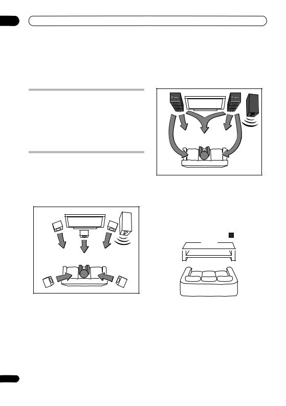
Home theater sound setup
Most 5.1 channel home theater systems are designed so that speakers are placed to surround the listener’s position as shown in the illustration. Such designs, however, produce the undesirable effect of forcing the center speaker to be mounted above or below the television monitor, and require room for the surround speakers.
Front left |
Bass |
Front right |
|
|
Center |
Surround left |
Surround right |
|
The present system, however, features Pioneer’s proprietary New Front Surround technology and Dual Center Speakers, using only two speaker positions (to right and left of television as shown in the illustration) in order to provide full home theater sound while greatly simplifying the issue of speaker placement.
|
Bass |
Front left |
Front right |
|
Center |
Surround left |
Surround right |
Front surround setup (recommended)
This recommended method places the surround speakers in front, to simplify the issue of speaker placement in the room. The center speakers can be placed in independently in the center if desired.
Surround |
Surround |
left |
right |
Center |
Center |
Front |
Front |
left |
right |
Receiver subwoofer
Listening position
*When center speakers are placed in the center.
Surround |
Surround |
left |
right |
Front |
Front |
left |
right |
|
Center |
6
En
Speaker Setup Guide |
01 |
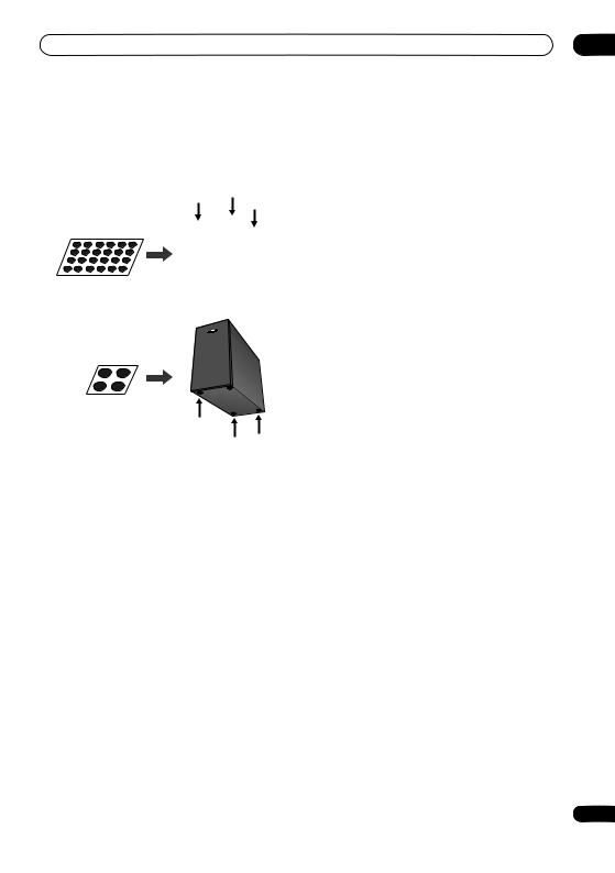
1 Attach the smaller non-skid pads to the base of each of the front, center and surround speakers. The four large non-skid pads are for the receiver subwoofer (as shown).
Use the adhesive side of the pads to attach them to the base (flat surface) of each speaker.
As shown in the illustration, stack the speakers from the bottom up in the order front speaker, center speaker, surround speaker. Align the bracket with the respective upper screw hole on the back of the front speaker, the two screw holes on the center speaker, and the bottom screw hole on the surround speaker, and fasten the screws securely.
Bracket
|
|
Surround speaker |
Non-skid pads |
|
Center speaker |
(small) x 24 |
Front, Center and Surround speakers |
|
|
|
|
|
|
Screw |
|
|
Front speaker |
Non-skid pads (large) x 4
Receiver subwoofer
2 Stack the speakers and fix with the brackets.
Each speaker is provided with a color-coded indicator on the model label on the rear side to assist identification. Refer to the color indicators and install the speakers correctly.
|
Left |
|
Right |
Model label |
Blue |
Surround speaker |
Gray |
|
|
|
|
|
|
|
|
|
Green |
Center speaker |
Green |
|
|
|
|
Color indicator |
White |
Front speaker |
Red |
|
|
|
|
When placing the center speakers independently, stack the front speaker on the bottom and the surround speaker on top, then align the 1st and 3rd screw holes from the top of the bracket with the upper screw holes on the back of the speakers, and fasten the two securely.
Bracket
Surround speaker
Front speaker |
Screw |
|
 Caution
•Do not attempt to carry the speakers when they are connected with the bracket. Doing so may cause damage to the bracket or worsen damage to the bracket and speakers in the event they are dropped.
3 Connect the speaker system.
Refer to Connecting up to connect the speakers properly. After connecting everything, place the speakers as shown in the diagram above for optimal surround sound. After placing the speakers, run the Auto MCACC setup (page 24) to complete your surround sound setup.
7
En
01 Speaker Setup Guide
Standard surround setup
This is a standard multichannel surround sound speaker setup for optimal 5.1 channel home theater sound.
The center speakers can be installed independently in the center if desired.
Center |
Center |
Front |
Front |
left |
right |
Receiver subwoofer
Listening position
Surround left |
Surround right |
*When center speakers are placed in the center.
Front |
Front |
left |
right |
Center |
1 Attach the smaller non-skid pads to the base of each of the front, center and surround speakers. The four large non-skid pads are for the receiver subwoofer (as shown).
Use the adhesive side of the pads to attach them to the base (flat surface) of each speaker.
Non-skid pads |
|
(small) x 24 |
Front, Center and Surround speakers |
|
Non-skid pads (large) x 4
Receiver subwoofer
8
2 (When mounting center speakers to right and left) Stack the speakers and fix with the bracket.
Each speaker is provided with a color-coded indicator on the model label on the rear side to assist identification. Refer to the color indicators and install the speakers correctly.
Model label |
Left |
|
Right |
|
|
|
|
|
Green |
Center speaker |
Green |
|
White |
Front speaker |
Red |
|
Color indicator |
|
|
As shown in the illustration, stack the speakers with the front speaker on the bottom and center speaker on top, then align the 1st and 3rd screw holes from the top of the bracket with the upper screw holes on the back of the speakers, and fasten the two securely.
Bracket
Center speaker
Front speaker |
Screw |
|
 Caution
•Do not attempt to carry the speakers when they are connected with the bracket. Doing so may cause damage to the bracket or worsen damage to the bracket and speakers in the event they are dropped.
3 Connect the speaker system.
Refer to Connecting up to connect the speakers properly. After connecting everything, place the speakers as shown in the diagram above for optimal surround sound. After placing the speakers, run the Auto MCACC setup (page 24) to complete your surround sound setup.
En
Speaker Setup Guide
Wall mounting the speakers
The front, center and surround speakers have a mounting hole which can be used to mount the speaker on the wall.
Before mounting
•Remember that the speaker system is heavy and that its weight could cause the screws to work loose, or the wall material to fail to support it, resulting in the speaker falling. Make sure that the wall you intend to mount the speakers on is strong enough to support them. Do not mount on plywood or soft surface walls.
•Mounting screws are not supplied. Use screws suitable for the wall material and support the weight of the speaker.
 Caution
•If you are unsure of the qualities and strength of the wall, consult a professional for advice.
•Pioneer is not responsible for any accidents or damage that result from improper installation.
5 mm
10 mm
5 mm to 7 mm
01
Additional notes on speaker placement
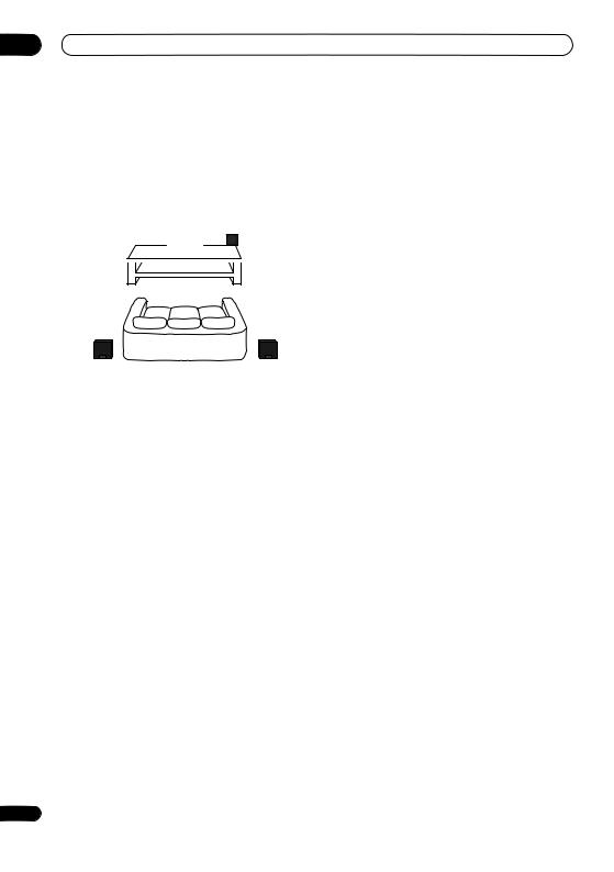
•Install the main front left and right speakers at an equal distance from the TV.
•When using the Front surround setup, separate the left and right speakers by about 1.5 m for optimum effect.
•When using the Standard surround setup, install the surround speakers slightly above ear level for optimum effect.
Precautions:
•When installing the center speaker on top of the TV, be sure to secure it with tape or some other suitable means. Otherwise, the speaker may fall from the TV due to external shocks such as earthquakes, endangering those nearby or damaging the speaker.
•The front (x2), center (x2) and surround (x2) speakers supplied with this system are magnetically shielded. However, depending on the installation location, color distortion may occur if the speaker is installed extremely close to the screen of a television set. If this happens, turn the power switch of the television set OFF, and turn it ON after 15 min to 30 min. If the problem persists, place the speaker system away from the television set.
•The receiver subwoofer is not magnetically shielded and so should not be placed near a TV or monitor. Magnetic storage media (such as floppy discs and tape or video cassettes) should also not be kept close to the receiver subwoofer.
•Do not attach the receiver subwoofer to the wall or ceiling. They may fall off and cause injury.
•For safety, make sure that there is no exposed bare speaker wire outside of the speaker terminals.
•Do not connect the supplied speakers with any other amplifier. This may result in malfunction or fire.
•Do not connect any speakers other than those supplied to this system.
9
En

02 Connecting up
Chapter 2
Connecting up
Basic connections
 Important
•When connecting this system or changing connections, be sure to switch power off and disconnect the power cord from the wall socket.
After completing all connections, connect the power cords to the wall socket.
Receiver subwoofer (SX-LX60D)
 FM antenna
3 AM loop antenna
4
|
|
|
|
|
|
|
|
|
|
|
|
|
|
|
|
|
HDD/DVD Recorder (DVR-LX60D) |
|
|
|
|
|
|
|
|
|
|
|
ANTENNA |
R |
AUDIO |
L VIDEO |
|
|
|
|
DIGITAL |
|
|
|
|
|
|
|
|
|
|
IN |
|
|
|
S-VIDEO |
|
|
|
AUDIO OUT |
|
|
|
|
|
|
|
|
|
|
|
|
|
|
|
|
|
|
|
|
|
|
|
|
|
|
|
|
|
|
|
|
|
INPUT 3 |
|
|
|
AC IN |
|
|
|
|
|
|
|
|
|
|
|
|
|
|
AV 2 (INPUT 1/DECODER) |
|
|
HDMI OUT |
COAXIAL |
|
|
|
|
|
|
|
|
|
|
|
|
|
|
G-LINK |
IN |
ANTENNA(DIGITAL) |
|
|
|
|
|
|
|
|
|
|
|
|
|
|
|
|
|
|
OUT |
IN |
|
|
|
|
|
|
|
|
|
|
|
OUT |
|
|
|
OUTPUT |
|
|
|
|
|
|
|
|
|
|
|
|
|
|
|
|
|
|
|
|
|
|
|
|
|
|
|
|
|
|
|
|
|
|
Y |
PB |
PR |
AV 1 (RGB) ñ TV |
CONTROL |
5 V |
30 mA |
|
|
|
|
|
|
ANTENNA |
|
|
|
|
COMPONENT VIDEO OUT |
|
|
|
|
|
|||
|
|
|
|
|
|
|
|
|
|
|
|
|
|
|
|
|
||
|
|
|
|
|
FM UNBAL 75 |
AM LOOP ANTENNA |
|
|
|
|
|
|
|
1 |
|
|
||
|
|
|
MCACC |
|
|
AUDIO INPUT |
|
|
|
|
|
|
|
|
|
|
||
|
|
|
SETUP MIC |
CONTROL IN |
|
|
|
|
|
|
|
|
|
|
|
|||
|
OUT |
SUBWOOFER |
R SURROUND L |
|
DIGITAL |
|
|
b |
Coaxial cable |
|
|
|
|
|||||
SYSTEM CONNECTOR |
CONTROL |
|
SPEAKERS |
|
(COAXIAL) |
(OPTICAL) |
(OPTICAL) |
ANALOG |
|
|
|
|
|
|
|
|
|
|
|
|
|
|
|
DVD/DVR1 |
DVD/DVR2 |
DIGITAL |
|
|
|
|
|
|
|
|
|
|
|
|
L |
|
Display unit |
USE ONLY WITH DISPLAY UNIT. |
R |
a Control cable |
|
|
|
||
CENTER R FRONT L |
|
|
|
SEE INSTRUCTION MANUAL. |
|
|
|
AC IN |
|
|
2 |
|
|
Display cable |
|
|
|
|
|
Note |
|
|
WARNING |
• When using the display unit in a wall-mounted |
• Pioneer bears no responsibility for accidents |
||
location, take full precautions to prevent the unit |
resulting from faulty assembly or installation, |
||
from accidentally falling. |
|
|
insufficient mounting strength of walls, mounting |
• Screws and other fixtures for use in wall mounting |
fixtures (or other building fixtures), misuse or natural |
||
are not included. |
|
|
disasters. |
10
En
Connecting up |
02 |
1 Connect the HDD/DVD recorder to the receiver subwoofer.
a.Plug the control cable into the CONTROL OUT jack on the rear of the receiver subwoofer.
Plug the other end of the cable into the CONTROL IN jack on the rear of the HDD/DVD recorder.
b.Plug the coaxial cable into the DIGITAL AUDIO INPUT (DVD/DVR 1) jack on the rear of the receiver subwoofer.
Plug the other end of the cable into the DIGITAL AUDIO OUT (COAXIAL) jack on the rear of the HDD/ DVD recorder.
Note that unless the control cable is connected, you can’t use the remote control with the HDD/DVD recorder.
2 Fasten the spacers to the display unit and connect.
If the display unit is difficult to view, the spacers can be attached to allow changing of the viewing angle. Peel off the protective paper from the spacers and press the spacers onto the depressions on the bottom of the display unit.
Plug the L-shaped end of the display cable into the connector on the rear of the display unit, then plug the other end of the display cable into SYSTEM CONNECTOR jack on the receiver subwoofer.
3 Assemble the AM loop antenna.
a |
b |
c |
a.Bend the stand in the direction indicated by the arrow.
b.Clip the loop onto the stand.
c.If you want to fix to a wall or other surface, perform step b after first securing the stand with screws.
It is recommended that you determine the reception strength before securing the stand with the screws.
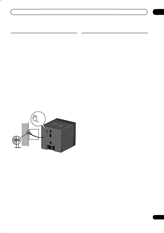
4Connect the AM and FM antennas1.
a.Connect one wire of the AM loop antenna to each AM antenna terminal2.
For each terminal, press down on the tab to open; insert the wire, then release to secure.
1


 2
2
b.Push the FM antenna3 plug onto the center pin of the FM antenna socket.
 Note
Note
1 • Keep antenna cables away from other cables, the display unit, receiver subwoofer and HDD/DVD recorder.
•If reception with the supplied antenna is poor, see Improving poor FM reception and Improving poor AM sound on page 29 or Connecting external antennas on page 34.
•Do not attach any antenna other than the provided loop antenna, or an external antenna as described on page 34.
2 • Don’t let it come into contact with metal objects and avoid placing near computers, television sets or other electrical appliances.
•If radio reception is poor, you may be able improve it by re-inserting each antenna wire into the opposite terminal.
•For best reception, do not untwist the AM loop antenna wires or wrap them around the loop antenna.
3 To ensure optimum reception, make sure the FM antenna is fully extended and not coiled or hanging at the rear of the unit.
11
En

02 Connecting up
Receiver subwoofer (SX-LX60D)
6 |
ANTENNA |
|
|
|
|
FM UNBAL 75 |
AM LOOP ANTENNA |
||
|
|
MCACC |
|
|
AUDIO INPUT |
|
|
|
|
SETUP MIC |
CONTROL IN |
|
|
||
|
|
|
|
|
DIGITAL |
|
|
SYSTEM CONNECTOR CONTROL |
|
SPEAKERS |
|
DVD/DVR1 |
DVD/DVR2 |
DIGITAL |
ANALOG |
OUT |
SUBWOOFER |
R SURROUND L |
(COAXIAL) |
(OPTICAL) |
(OPTICAL) |
|
|
|
|
|
|
5 |
|
L |
|
USE ONLY WITH DISPLAY UNIT. |
|
|
|
|
R |
||
|
|
|
|
|
|||
SEE INSTRUCTION MANUAL. |
|
|
|
|
|
||
|
CENTER |
R FRONT |
L |
|
|
|
|
AC IN
Surround right |
Surround left |
(Gray) |
(Blue) |
Center |
Listening position |
Center |
|
(Green) |
(Green) |
||
|
|||
|
Y-cable |
|
|
Front right |
|
Front left |
|
(Red) |
|
(White) |
8 |
Speaker system (SSP-LX60D) |
To AC outlet |
5Connect each speaker.
•The front and surround speaker cables have a colorcoded connector at one end and two bare wires at the other end.
•When connecting the center speakers, connect the Y- cable dual end to the two center speakers in the same way.
Color-coded wire (Connect to speaker)
Color-coded connector (Connect to rear panel)
•Since there is only one terminal to connect the two center speakers, you will need to use the supplied Y- cable for the connection.
•Twist and pull off the protective shields on each wire.
•Connect the wires to the speaker. Each speaker in the illustration can be identified by means of the colorcoded indicator provided on the rear-surface model label. Match the color-coded wire with the color indicator on the model label, then insert the colorcoded wire into the red (+) side and the other wire into the black (–) side.
Y-cable

 To Receiver subwoofer
•Connect the other end to the color-coded speaker terminals on the rear of the receiver subwoofer. Make sure to insert completely.
The small lug at the wire-end of the speaker plug should face up or down depending on whether it’s being plugged into one of the upper or lower speaker terminals. Please make sure to connect correctly.
Upper terminal |
Lower terminal |
12
En
Connecting up |
02 |
•When connections are completed, adjust the cable placements. If the speakers have been fixed with the brackets, fix the cable to the groove in the brackets as shown.
•Fasten the cables together with the spiral wrap. Hold multiple cables together and place the wrap over the cables from the end.
Wrap the spiral wrap with the cables in the center. The spiral wrap may be cut at a desired length.
6Connect the subwoofer cable.
•Just below the subwoofer speaker, to the left of center, you should see the subwoofer connecting cable. Plug this into the SUBWOOFER SPEAKER terminal.
 Caution
•These speaker terminals carry HAZARDOUS LIVE voltage. To prevent the risk of electric shock when connecting or disconnecting the speaker cables, disconnect the power cord before touching any uninsulated parts.
•Do not connect any speakers other than those supplied to this system.
•Do not connect the supplied speakers to any amplifier other than the one supplied with this system. Connection to any other amplifier may result in malfunction or fire.
•The center speakers and front/surround speakers are designed with different impedance values. Be sure to identify and connect the speakers correctly since improper connections may result in degraded sound or operation.
13
En

02 Connecting up
Antenna wall outlet |
Antenna wall outlet |
RF antenna cable |
or indoor antenna |
|
ANTENNA |
7 |
RF antenna cable |
HDD/DVD Recorder |
|
(DVR-LX60D) |
||||
IN |
|
|
ANTENNA |
R AUDIO |
L |
VIDEO |
|
|
|
|
|
DIGITAL |
|
|
|
|
|
|
|
|
|
S-VIDEO |
|
|
|
|
|
ANTENNA |
|
|
|
|
|
|
IN |
|
|
|
|
|
|
|
AUDIO OUT |
|
|
|
|
|
|
|
|
|
|
INPUT 3 |
AV 2 (INPUT 1/DECODER) |
|
|
|
(DIGITAL) IN |
|
|
|
|
AC IN |
||
|
|
|
|
|
|
|
|
HDMI OUT |
COAXIAL |
|
|
|
|
|
|
|
|
|
|
G-LINK |
IN |
ANTENNA(DIGITAL) |
|
|
|
|
|
|
|
||
|
|
|
|
OUT |
IN |
|
|
|
|
|
|
|
|||
|
|
|
|
|
|
|
|
|
|
|
|
|
|
||
OUT |
|
|
OUTPUT |
|
|
|
|
|
|
|
|
|
|
|
|
|
|
|
|
|
|
|
|
|
|
|
|
|
|
|
|
|
Y |
PB |
PR |
AV 1 (RGB) ñ TV |
|
CONTROL |
5 V |
30 mA |
|
|
|
|
|
|
|
|
COMPONENT VIDEO OUT |
|
|
|
|
|
|
|
|
|
|
|
|||
|
|
|
|
|
|
|
|
|
|
|
|
|
|||
ANTENNA |
|
|
|
|
|
|
|
|
|
|
|
8 |
|
|
|
OUT |
|
|
|
|
|
|
|
|
|
|
|
|
|
||
|
|
|
|
|
|
|
|
|
|
|
|
|
|
|
|
|
|
|
7 |
To Video input |
|
|
|
|
|
|
|
|
|
|
|
|
|
|
|
|
|
|
|
|
|
|
|
|
|
|
To AC outlet |
7 |
Audio/video cable |
|
|
|
|
|
|
|
|
|
|
|
|
||
|
(red/white/yellow) |
To Audio input |
|
|
|
|
|
|
|
|
|
|
|
||
|
|
|
|
|
|
|
|
|
|
|
|
|
|
|
|
RF antenna cable |
|
|
|
|
|
|
|
|
|
|
|
|
|
|
|
|
|
|
|
To Antenna in |
|
|
|
|
TV |
|
|
|
|
|
|
|
|
|
|
|
|
|
|
|
|
|
|
|
|
||
7 Connect the HDD/DVD recorder to your TV. |
1 |
|
|
SYSTEM CONNECTOR CONTROL |
MCACC |
CONTROL IN |
DVD/DVR1 |
DVD/DVR2 |
DIGITAL |
ANALOG |
|||||
|
|
SPEAKERS |
|||||||||||||
|
|
|
|
|
|
|
|
|
SETUP MIC |
|
AUDIO INPUT |
|
|||
|
|
|
|
|
|
|
|
|
|
|
|
DIGITAL |
|
|
|
• Connect the VIDEO OUTPUT jack to a video input on |
|
OUT |
SUBWOOFER |
R SURROUND L |
(COAXIAL) |
(OPTICAL) |
(OPTICAL) |
|
|||||||
|
|
|
|
|
|
|
|
L |
|||||||
your TV. |
|
|
|
|
|
|
|
USE ONLY WITH DISPLAY UNIT. |
|
|
|
|
|
|
R |
|
|
|
|
|
|
|
|
|
|
|
|
|
|
||
|
|
|
|
|
|
|
|
SEE INSTRUCTION MANUAL. |
|
|
|
|
|
|
|
Use the yellow jack of the supplied audio/video cable |
|
|
CENTER |
R FRONT |
L |
|
|
|
|
||||||
|
|
|
|
|
|
|
|
|
|||||||
for the video connection. |
|
|
|
|
|
AC IN |
|
|
|
|
|
|
|
||
• Connect the AUDIO OUTPUT jacks to the |
|
|
|
|
|
|
|
|
|
|
|
||||
corresponding audio inputs on your TV. |
|
|
|
|
|
|
|
|
|
|
1 |
||||
Use the red and white jacks of the supplied audio/ video cable for the audio connection. Make sure you match the left and right outputs with their corresponding inputs for correct stereo sound.
•See Connecting a TV antenna on page 49 to connect the antenna.
8Connect the power cord.2
•Connect the power cord to AC inlet on the receiver subwoofer and HDD/DVD recorder. Connect the power cord to a wall socket.
Using this system for TV audio
If your TV has a stereo audio output you can connect it to this system and enjoy surround TV sound.
 Important
•When connecting this system, be sure to switch power off and disconnect the power cord from the wall socket. Connect the power cord to the wall socket only after completing all other connections.
To Audio output
TV
1 Connect the audio output jacks on your TV to the ANALOG AUDIO INPUT jacks on the receiver subwoofer.
Use the red/white stereo audio cable (not supplied) for this connection. Make sure you match the left and right outputs with their corresponding inputs for correct stereo sound.
•You can use the ANALOG AUDIO INPUT jacks for any analog source you want, such as a tape deck, etc.
 Note
Note
1 Other types of video connection are possible. See page 50 to page 52 for more on this. 2 • Do not use any power cord other than the one supplied with this system.
• Do not use the supplied power cord for any purpose other than connecting to this system.
14
En
Controls and displays |
03 |
Chapter 3
Controls and displays
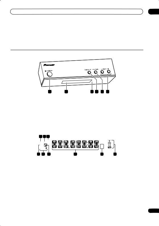
Display unit
|
1 |
2 |
|
3 |
4 |
5 |
6 |
1 |
STANDBY/ON |
|
4 |
AUDIO INPUT (page 33) |
|||
Press to switch the system on/into standby. |
|
Press repeatedly to select one of the external audio |
|||||
2 |
Front panel display |
|
inputs (DVD/DVR1, DVD/DVR2, DIGITAL or ANALOG). |
||||
|
|
|
|
|
|
||
See below for details. |
|
5 |
SURROUND |
|
|
||
3 |
IR remote sensor (page 20) |
|
Use to select a Surround mode (page 26). |
||||
|
|
|
|
|
|
||
|
|
|
6 |
VOLUME +/– buttons |
|||
|
|
|
Use to adjust the volume. |
||||
Display
1 |
2 |
3 |
|
|
SOUND |
|
|
DTS F.SURR. |
|
||
2D |
|
|
|
2PL |
|
|
|
9 |
8 |
7 |
6 |
1 DTS
Lights during playback of a DTS source (page 26).
2F.SURR.
Lights when one of the Front Stage Surround Advance listening modes is selected (page 27).
SURR.
Lights when one of the Advanced Surround listening modes is selected (page 27).
3SOUND
Lights when Sound Retriever is active (page 27).
4Tuner indicators

 – Lights when a broadcast is being received.
 – Lights when a stereo FM broadcast is being received in auto stereo mode.
kHz MHz
5 4
 – Lights when FM mono reception is selected.
 – Lights when in one of the RDS display or search modes.
5 kHz/MHz
Indicates the frequency unit shown in the character display (kHz for AM, MHz for FM).
6Character display
7
Lights when sleep timer is active (page 36).
8 2 PL II
Lights during Dolby Pro Logic II decoding (page 26).
9 2 D
Lights during playback of a Dolby Digital source (page 26).
15
En
03 Controls and displays
HDD/DVD Recorder
1 |
|
2 |
3 |
4 |
5 |
6 |
7 |
|
|
|
|
|
|
HDD/DVD |
|
OPEN/CLOSE |
|
|
|
|
|
|
A.TV |
D.TV PLTV DivX |
COPY |
|
|
HDMI |
|
|
|
|
STANDBY/ON |
DV IN |
USB |
COMMON INTERFACE |
|
|
INPUT 2 S-VIDEO |
VIDEO L(MONO) |
R |
AUDIO |
REC |
|
|
|
|
|
STOP REC |
ONE TOUCH |
|
|
|
|
|
|
|
|
|
|
COPY |
|
|
|
|
CH |
INPUT |
A.TV/D.TV |
SELECT |
8 |
9 |
10 |
11 |
9 |
12 |
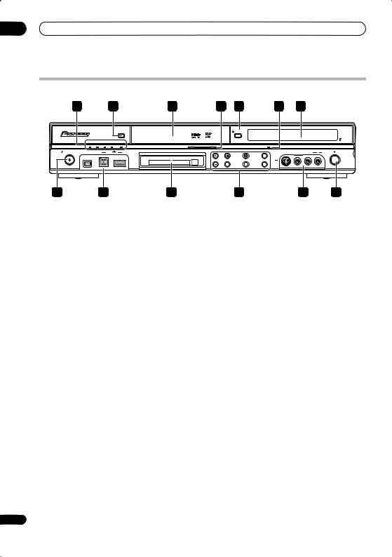
1A.TV indicator
Lights when analog TV is selected.
D.TV indicator
Lights when digital TV is selected.
PLTV indicator
Lights during recording started using the Pause Live TV feature.
DivX indicator
10 COMMON INTERFACE slot
Slot for CA module and smart card used to decode scrambled D.TV channels. See Common Interface on page 17.
Press to start or restart playback.
Press to stop playback.
Lights during DivX playback.
COPY indicator
Lights when copying is underway.
2 HDD/DVD
Press to switch between HDD and DVD for recording and playback.
3Disc tray
4HDD/DVD indicator
Indicator lights blue when the hard disk (HDD) is selected; orange when the DVD drive is selected.
5 OPEN/CLOSE
Press to open/close the disc tray.
6 HDMI indicator
Lights when this recorder is connected to HDMI (HDCP) compatible component.
7 Front panel display
See Display on page 17 for details.
8 STANDBY/ON
Press to switch the recorder on/into standby.
9 Front panel inputs
See Front panel connections on page 49 for more information on these.
STOP REC
Press to stop recording.
ONE TOUCH COPY
Press to start One Touch Copy of the currently playing title to DVD or the HDD.
CH +/–
Use to change channels, skip chapters/tracks, etc.
INPUT SELECT
Press to change the input used for recording.
A.TV/D.TV
Switches between analog TV antenna input and digital TV antenna input. The A.TV and D.TV indicators show which is selected.
12 REC
Press to start recording. Press repeatedly to set the recording time in 30 minute blocks.
16
En
Controls and displays |
03 |
Display
1 |
2 |
3 |
4 |
5 |
|
|
L |
R |
P |
8 7 6
1
Lights during playback; blinks when playback is paused.
2
Lights when copying.
3
Lights during recording; blinks when recording is paused.
4 (page 86)
Lights when a timer recording has been set. (Indicator blinks if the timer has been set to DVD but there isn’t a recordable disc loaded, or the timer has been set to HDD but the HDD is not recordable.)
NTSC
Lights when the video output signal format is NTSC.

 (page 140)
Indicates which channels of a bilingual broadcast are recorded.
 (page 139)
Lights when the component video output is set to progressive scan.
VPS/PDC (page 86)
Lights when receiving a VPS/PDC broadcast during a VPS/PDC-enabled timer recording.
5Recording quality indicators (page 83)
XP
Lights when the recording mode is set to XP (high quality).
SP
Lights when the recording mode is set to SP (standard play).
LP/SLP
Lights when the recording mode is set to LP (long play) or SLP (super-long play).
EP/SEP
Lights when the recording mode is set to EP (extended play) or SEP (super-extended play).
MN
Lights when the recording mode is set to MN (manual recording level) mode.
6Character display
7R/RW
Lights when a recordable DVD-R or DVD-RW disc is loaded.
8PL (page 105)
Lights when a VR mode disc is loaded and the recorder is in Play List mode.
2 3 (page 145)
Shows the remote control mode (if nothing is displayed, the remote control mode is 1).
V
Lights when an unfinalized Video mode disc is loaded.
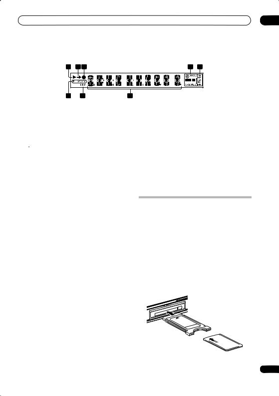
Common Interface
To receive scrambled D.TV channels you will need a CA module and smart card provided by your service provider.
Different CA modules support different encryption systems. This recorder is designed to work with modules that support the DVB standard. Contact your service provider to obtain the right kind of CA module.
Note that neither CA modules nor smart cards are supplied or sold by Pioneer.
Inserting a CA module
The Common Interface card slot is located on the front panel of the recorder.
• Insert the CA module into the card slot as far as it will go.
The Common Interface card slot accepts Type I and Type II PC Cards (PCMCIA cards).
17
En

03 Controls and displays
Remote control |
|
|
|
|
|
Important |
||
|
|
|
|
|
• Functions printed in green on the remote control are |
|||
|
|
|
|
|
|
|
|
|
|
RECORDER |
|
RECEIVER |
|
|
accessed by switching the MAIN SUB MAIN/SUB switch |
||
|
|
|
|
to SUB. |
||||
1 |
|
|
|
|
|
2 |
|
|
|
|
|
1 |
RECORDER |
||||
|
|
|
|
|
SOUND |
|
||
|
HDD/DVD |
FM/AM |
AUDIO IN |
|
RETRIEVER |
|
Press to switch the recorder on or into standby. |
|
3 |
|
|
|
|
|
4 |
||
|
|
|
|
|
2 |
RECEIVER |
||
|
PAUSE |
PLAY |
|
STOP |
|
|||
|
|
|
Press to switch the receiver subwoofer on or into standby. |
|||||
5 |
|
|
|
|
|
|||
|
|
|
|
|||||
6 |
REC |
STOP REC |
HELP |
|
INFO |
7 |
3 |
Input select buttons |
|
|
|
|
|
|
HDD/DVD (page 83) |
||
|
TOP MENU |
|
|
|
8 |
|
||
|
|
|
|
|
Press to select the hard disk (HDD) or DVD for |
|||
9 |
DISC |
HOME MENU |
|
GUIDE |
10 |
|
||
NAVIGATOR |
|
|
|
|
recording and playback. The receiver subwoofer’s |
|||
|
|
|
|
|
|
|||
12 |
CHANNEL |
|
|
|
CM BACK |
11 |
|
audio input is also switched to DVD/DVR1.1 |
|
|
|
|
|
|
FM/AM (page 29) |
||
|
|
|
|
|
|
|
|
|
|
|
ENTER |
|
|
|
|
Press to select the built-in radio tuner. |
|
|
CHANNEL |
|
|
|
CM SKIP |
|
|
AUDIO IN (page 33) |
|
|
|
|
|
|
Press repeatedly to select one of the receiver |
||
|
A.TV/ D.TV |
|
|
RETURN/EXIT |
|
|
||
13 |
|
|
|
|
|
14 |
|
subwoofer’s audio inputs (DVD/DVR1, DVD/DVR2, |
|
|
|
|
|
|
DIGITAL or ANALOG). |
||
|
PREV |
NEXT |
VOLUME |
|
|
|||
15 |
16 |
|
|
|||||
|
|
|
|
|
4 |
SOUND RETRIEVER |
||
|
|
|
|
|
|
|
Press to restore CD quality sound to compressed audio |
|
|
AUDIO |
SUBTITLE |
ANGLE |
|
MCACC |
|
sources (page 27). |
|
17 |
|
|
|
|
||||
|
|
|
|
|
18 |
5 |
Playback controls (page 91) |
|
19 |
/ / |
TIMER REC |
REC MODE |
|
PAUSE |
|||
|
|
|
|
|
20 |
|
||
|
SETUP |
/ TUNE+ |
SR + |
ONETOUCHCOPY |
|
|
Press to pause playback or recording. |
|
|
1 |
2 |
3 |
|
|
21 |
|
PLAY |
22 |
/ ST- |
ENTER |
/ ST+ PAUSE LIVE TV |
23 |
|
Press to start playback. |
||
4 |
5 |
6 |
|
|
|
STOP |
||
|
F. S. SURR |
/ TUNE- TEST TONE |
VIDEO IN |
|
|
|||
|
7 |
8 |
9 |
|
|
24 |
|
Press to stop playback. |
|
|
|
|
|
||||
|
SURROUND |
ADVANCED |
SOUND |
|
MENU |
|
6 Recording controls (page 83) |
|
|
|
0 |
|
|
|
25 |
||
|
|
|
|
|
|
REC |
||
|
SLEEP |
|
CLEAR |
|
JUKEBOX |
|
|
|
|
|
|
|
|
|
26 |
|
Press to start recording. Press repeatedly to set the |
27 |
INPUT |
CHANNEL |
VOLUME |
|
DISPLAY |
28 |
|
recording time in blocks of 30 mins. |
|
|
|
|
|
|
|
When the red action button is visible in a GUIDE |
|
|
|
TEXT |
TV/DVD |
|
RDS DISP |
|
|
Plus+® screen, use for One-Button-Record. |
29 |
|
TV CONTROL |
|
|
|
|
||
|
|
|
|
|
|
|||
MAIN |
SUB |
|
|
|
|
|
STOP REC |
|
|
|
|
|
|
|
|||
|
|
|
|
|
|
|
|
Press to stop recording. |
OPEN |
7 INFO |
|
While watching D.TV, press to display information |
|
banner. |
|
Press to see additional information highlighted item in |
|
the EPG. |
8 HELP
Press for help on how to use the current GUI screen.
 Note
Note
1 If the recorder is set to remote mode 2 or 3, the receiver subwoofer’s audio input will not be switched. See also Remote Control Mode on page 145.
18
En

Controls and displays |
03 |
9DISC NAVIGATOR (page 94, 105) / TOP MENU
(page 92)
Press to display the Disc Navigator screen, or the top menu if a DVD-Video or finalized DVD-R/-RW (Video) disc is loaded.
10GUIDE
Press to display the EPG screen; press again to exit.
11 HOME MENU
Press to display the Home Menu, from which you can navigate many functions of the system.
12/ / / and ENTER (Smart Jog)
Used to navigate all on-screen displays. Rotate the Smart Jog to move the cursor up or down. Press ENTER to select the currently highlighted option.
When using the Smart Jog, turn it lighty to avoid pressing down on the cursor keys.
While watching D.TV press ENTER to display the Channel List screen.
Rotate the Smart Jog when playback is paused to do a frame-by-frame search back/forward.
 CM BACK (commercial back)
Turn the Smart Jog counter-clockwise during playback to skip progressively backward through the video playing.
 CM SKIP (commercial skip)
Turn the Smart Jog clockwise during playback to skip progressively forward through the video playing.
CHANNEL +/– (page 81)
While stopped, turn the Smart Jog to change the channel of the built-in TV tuner.
13 A.TV/D.TV
Press to switch between analog TV antenna input and digital TV antenna input. The A.TV and D.TV indicators on the front panel show which is selected.
14 RETURN/EXIT
Press to go back one level in the on-screen menu or display.
Also press to exit the MHEG application.
15 PREV / NEXT
Press to skip to the previous or next title/chapter/track/ folder; or to display the previous or next menu page.
When GUIDE Plus+® is displayed, use to display the previous/next page.
16 VOLUME +/–
Use to adjust the volume.
17 GUIDE Plus+™ Action buttons
Use when an EPG screen is displayed or when tuned to a data channel of a digital broadcast. The function of each button will be described on-screen, and changes depending on the screen being displayed.
AUDIO (page 82, 98, 99)
Press to change the audio language or channel. (When the recorder is stopped, press to change the tuner audio.)
SUBTITLE (page 98)
Press to display/change the subtitles included in multilingual DVD-Video discs.
While watching D.TV, press to change the D.TV subtitles.
ANGLE (page 99)
Press to switch camera angles on discs with multiangle scenes.
MCACC
Starts the Auto MCACC setup (page 24).
18TIMER REC (page 63, 86) Press to set a timer recording.
19/ (page 95)
Press to start reverse or forward scanning. Press again to change the speed.
/ , / (page 96)
While paused, press and hold to start slow-motion playback. Press repeatedly to change the playback speed.
While paused, press to advance a single frame in either direction.
When GUIDE Plus+® is displayed, use to display the previous/next day.
20REC MODE (page 83)
Press repeatedly to change the recording mode (picture quality).
21 ONE TOUCH COPY (page 114)
Press to start One Touch Copy of the currently playing title to DVD or the HDD.
22Number buttons
Use the number buttons for track/chapter/title selection; channel selection, and so on.
/ / / (cursor buttons) and ENTER
Use to control receiver functions.
SETUP
Use to access the menu system for surround sound setup, tuner settings and so on (page 24, 29, 30, 31, 36).
SR+
Use to setup the SR+ features and to select the SR+ mode (page 35).
F.S.SURR
Use to select a Front Stage Surround Advance mode (page 27).
TEST TONE
Use to output the test tone (for speaker setup) (page 32).
19
En
03 Controls and displays
SURROUND
Use to select a Surround mode (page 26).
ADVANCED
Use to select a Pioneer original surround mode (page 27).
SOUND (page 28)
Press to access the sound menu, from which you can adjust bass and treble, etc.
SLEEP
Press to set the sleep timer (page 36).
CLEAR
Press to clear an entry and start again.
23 PAUSE LIVE TV (page 84)
Press to start recording the current TV channel, but with playback paused, effectively pausing the broadcast.
24 VIDEO IN (page 88)
Press to change the HDD/DVD recorder input to use for recording.
25 MENU (page 92)
Press to display the disc menu if a DVD-Video, finalized DVD-R/-RW (Video mode) or finalized DVD+R/+RW disc is loaded.
When in the GUIDE Plus+® system, use to jump directly to the Menu bar.
26 JUKEBOX (page 121)
Press to display the Jukebox screen of the HDD/DVD recorder, from where you can copy music to the HDD for playback.
27TV CONTROL (page 148)
After setting up, use these controls to control your TV.
TEXT (page 82)
Press to display Teletext information (in European countries except the UK) or to start the MHEG application display (UK only) if available during digital broadcasts.
TV/DVD
Press to switch between ‘TV mode’, in which you get the picture and sound from the TV’s tuner, and ‘DVD mode’, in which you get picture and sound from the system’s tuner (or an external input).
28DISPLAY (page 99)
Displays/changes the on-screen information displays.
RDS DISP
Changes RDS displays (page 30).
29MAIN/SUB
Change from MAIN to SUB to access the green functions/commands on the remote.
20
Using the remote control
Please keep in mind the following when using the remote control:
•Make sure that there are no obstacles between the remote and the remote sensor on the unit.
•Remote operation may become unreliable if strong sunlight or fluorescent light is shining on the unit’s remote sensor.
•Remote controllers for different devices can interfere with each other. Avoid using remotes for other equipment located close to this unit.
•Replace the batteries when you notice a fall off in the operating range of the remote.
•When the batteries run down or you change the batteries, the remote control mode is reset to Recorder 1. See Remote Control Mode on page 145.
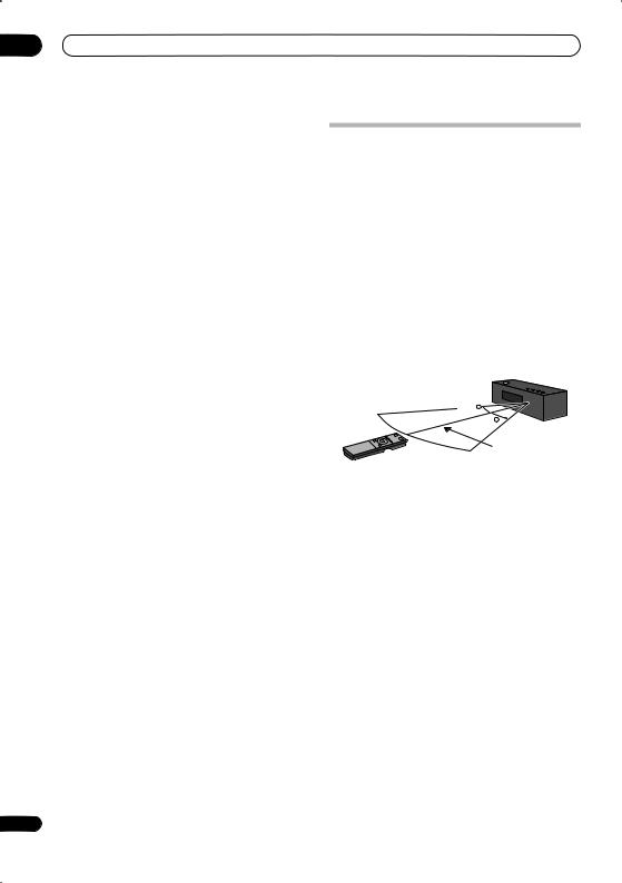
•Use within the operating range in front of the remote control sensor on the display unit, as shown.
30 

30
7 m
En
Controls and displays |
03 |
Putting the batteries in the remote control
1Open the battery compartment cover on the back of the remote control.
2Insert two AA/R6 batteries into the battery compartment following the indications ( , ) inside the compartment.
3 Close the cover.
 Caution
Incorrect use of batteries can result in hazards such as leakage and bursting. Please observe the following:
•Don’t mix new and old batteries together.
•Don’t use different kinds of battery together — although they may look similar, different batteries may have different voltages.
•Make sure that the plus and minus ends of each battery match the indications in the battery compartment.
•Remove batteries from equipment that isn’t going to be used for a month or more.
•When disposing of used batteries, please comply with governmental regulations or environmental public instruction’s rules that apply in your country or
area.
 WARNING
•Do not use or store batteries in direct sunlight or other excessively hot place, such as inside a car or near a heater. This can cause batteries to leak, overheat, explode or catch fire. It can also reduce the life or performance of batteries.
21
En
04 Before you start
Chapter 4
Before you start
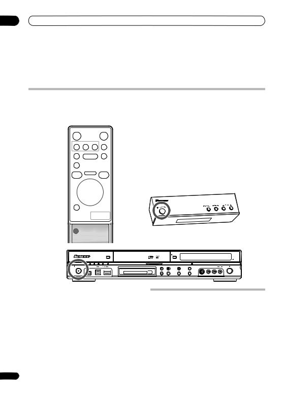
Switching on
The HDD/DVD recorder and receiver subwoofer have separate power switches. The power switch for the receiver subwoofer is located on the display unit.
Remote Control
RECORDER |
RECEIVER |
SOUND
HDD/DVD FM/AM AUDIO IN RETRIEVER
PAUSE |
PLAY |
STOP |
|
|
|
REC |
STOP REC HELP |
INFO |
|
|
|
TOP MENU |
|
|
DISC |
HOME MENU |
GUIDE |
NAVIGATOR |
|
|
CHANNEL |
|
CM BACK |
|
ENTER |
|
CHANNEL |
|
CM SKIP |
A.TV/ D.TV |
|
RETURN/EXIT |
PREV NEXT VOLUME
OPEN |
Display Unit
HDD/DVD Recorder (DVR-LX60D)
|
|
|
HDD/DVD |
OPEN/CLOSE |
|
|
|
|
|
|
A.TV |
D.TV PLTV DivX |
COPY |
|
HDMI |
|
|
|
|
STANDBY/ON |
DV IN |
USB |
COMMON INTERFACE |
|
INPUT 2 S-VIDEO |
VIDEO L(MONO) |
R |
AUDIO |
REC |
|
|
|
|
STOP REC |
ONE TOUCH |
|
|
|
|
|
|
|
|
COPY |
|
|
|
|
|
|
|
|
CH |
INPUT |
A.TV/D.TV |
|
|
|
|
|
|
|
SELECT |
|
|
|
|
The table below shows what needs to be switched on for various system functions:
Function |
Display unit |
HDD/DVD |
|
recorder |
|||
|
|
||
DVD playback |
On |
On |
|
|
|
|
|
CD playback |
On |
On |
|
|
|
|
|
HDD playback |
On |
On |
|
|
|
|
|
Radio |
On |
Off |
|
|
|
|
|
Timer recording |
Off |
On |
|
|
|
|
Setting up
After connecting and installing the HDD/DVD recorder and receiver subwoofer, complete the steps below to set the system up for use.
HDD/DVD recorder
•Set the date and time, TV channel tuning and the type of TV in the Setup Navigator (page 56).
Receiver subwoofer
•Switch off the display demo mode (page 24).
•Complete the Auto MCACC setup to optimize the surround sound (page 24).
22
En
Before you start
Basic operation
This manual is split into to parts, one covering using the receiver subwoofer, the other using the HDD/DVD recorder. Below are some common operations and where to find them explained in this manual.
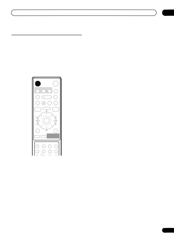
Watching a DVD
Remember that when using the remote to control the HDD/DVD recorder, you should point the remote towards the display unit, not the recorder itself.
RECORDER |
RECEIVER |
SOUND
HDD/DVD FM/AM AUDIO IN RETRIEVER
PAUSE |
PLAY |
STOP |
|
|
|
|
|
REC |
STOP REC |
HELP |
INFO |
|
|
|
|
TOP MENU |
|
|
|
DISC |
HOME MENU |
GUIDE |
|
NAVIGATOR |
|
|
|
CHANNEL |
|
|
CM BACK |
|
ENTER |
|
|
CHANNEL |
|
|
CM SKIP |
A.TV/ D.TV |
|
|
RETURN/EXIT |
PREV |
NEXT |
VOLUME |
|
|
|
|
|
AUDIO |
SUBTITLE |
ANGLE |
MCACC |
/ / |
TIMER REC |
REC MODE |
|
SETUP |
/ TUNE+ |
SR + ONETOUCHCOPY |
1Switch on the display unit (receiver subwoofer).
2Switch on the HDD/DVD recorder.
3Switch on your TV.
Turn on your TV and make sure that it is set to the correct video input.
4Press HDD/DVD to select DVD.
5Press OPEN/CLOSE on the HDD/DVD recorder to open the disc tray.
6Load a disc.
Load a disc with the label side facing up, using the disc tray guide to align the disc (if you’re loading a doublesided DVD disc, load it with the side you want to play face-down).
04
7Press (play) to start playback.
Press to stop playback.
You can resume playback from the same point by pressing . (Press again to cancel the resume function.)
Pauses playback, or restarts playback when paused.
|
Press to start scanning. Press repeatedly |
|
to increase the scanning speed. |
|
|
See Basic playback on page 91 for more on playing discs.
8Adjust the volume.
9Adjust the sound using the surround effects.
See Listening to your system on page 26 for details.
Listening to a CD
1Switch on the display unit (receiver subwoofer).
2Switch on the HDD/DVD recorder.
3Press HDD/DVD to select DVD.
4Load a CD and start playback (page 93).
5Adjust the volume.
6Adjust the sound using the surround effects
(page 26).
Watching a title recorded on the HDD
1Switch on the display unit (receiver subwoofer).
2Switch on the HDD/DVD recorder.
3Switch on your TV.
4Press HDD/DVD to select HDD.
5Start playback of the HDD title (page 92).
6Adjust the volume.
7Adjust the sound using the surround effects
(page 26).
Listening to the radio
1Switch on the display unit (receiver subwoofer).
2Tune to a station (page 29).
3Adjust the volume.
4Adjust the sound using the surround effects
(page 26).
23
En
05 Getting started
Chapter 5
Getting started
 Important
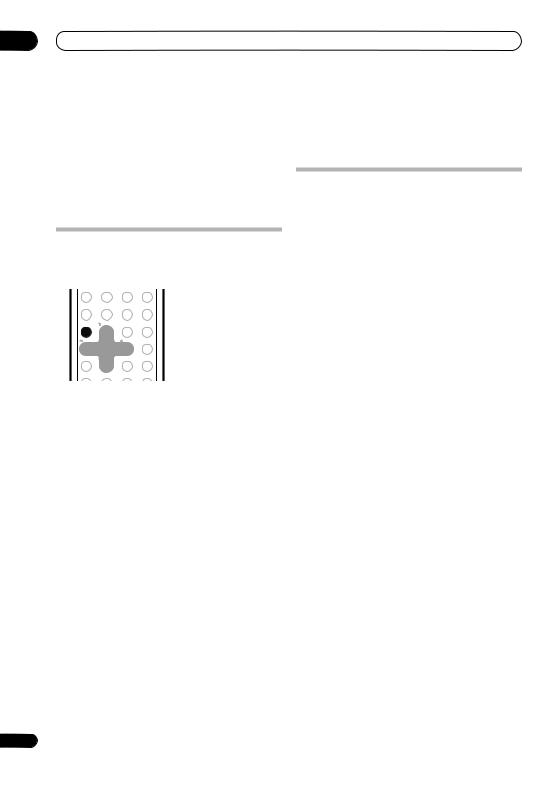
•To access green functions on the remote, move the slider switch from MAIN to SUB.
System demo setting
Switches the automatic demo feature on or off (this starts when you plug in for the first time).
AUDIO SUBTITLE ANGLE |
MCACC |
0 |
|
|
|
|
|
|
SLEEP |
CLEAR |
JUKEBOX |
/ / TIMER REC REC MODE |
|
|
|
|
|
INPUT |
CHANNEL |
VOLUME |
DISPLAY |
SETUP |
/ TUNE+ |
SR + ONETOUCHCOPY |
|
|
|
|
1 |
2 |
3 |
|
TEXT |
TV/DVD |
RDS DISP |
/ ST- |
ENTER |
/ ST+ PAUSE LIVE TV |
TV CONTROL |
|
||
4 |
5 |
6 |
MAIN |
SUB |
|
|
F. S. SURR |
/ TUNE- TEST TONE |
VIDEO IN |
|
|
|
|
7 |
8 |
9 |
|
|
|
|
SURROUND |
ADVANCED |
SOUND |
MENU |
|
|
|
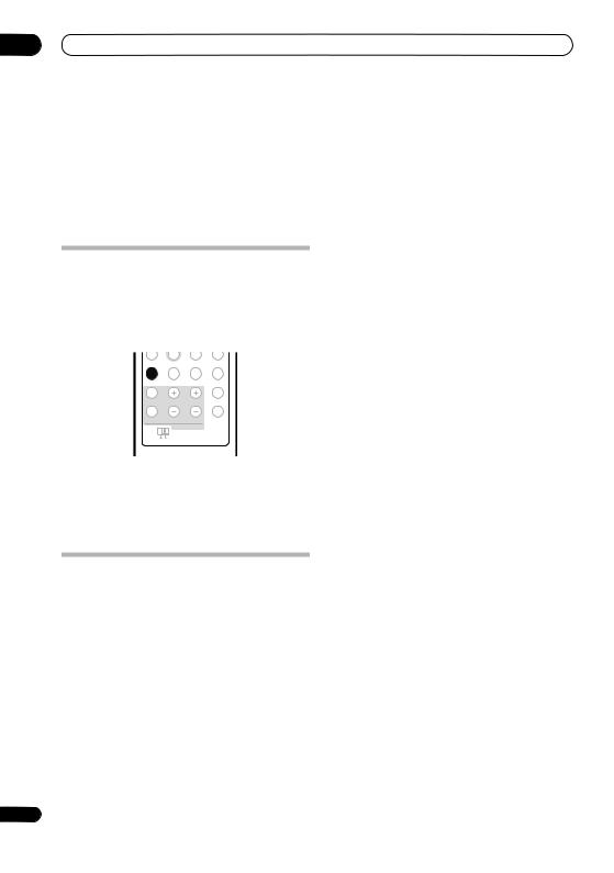
1Switch the system into standby.
2Press SETUP.
3Use the / buttons to select DEMO from the menu, then press ENTER.
4Use the / buttons to select a setting, then press ENTER.
Select from:
•DEMO ON – Switches the demo display on.
•DEMO OFF – Switches the demo display off and the system into standby.
Using the Auto MCACC setup for optimal surround sound
The Multichannel Acoustic Calibration (MCACC) system measures the acoustic characteristics of your listening area, taking into account ambient noise, and testing for channel delay and channel level. After you have set up the microphone provided, the system uses the information from a series of test tones to optimize the speaker settings and equalization (Acoustic Calibration
EQ) for your particular room.1
 Important
•The test tones used for Auto MCACC setup are loud; however, do not turn the volume down during setup as this may result in a sub-optimal setup.
•Make sure the microphone and speakers are not moved during the MCACC setup.
RECORDER |
|
RECEIVER |
AUDIO |
SUBTITLE |
ANGLE |
MCACC |
||
|
|
|
|
|
|
|
|
|
|
|
|
|
/ / |
TIMER REC |
REC MODE |
||
HDD/DVD |
FM/AM |
AUDIO IN |
SOUND |
|
|
|
|
|
RETRIEVER |
|
|
||||||
|
|
|
|
SETUP |
/ TUNE+ |
SR + ONETOUCHCOPY |
||
PAUSE |
PLAY |
STOP |
1 |
2 |
3 |
|
||
|
|
|
/ ST- |
ENTER |
/ ST+ PAUSE LIVE TV |
|||
4 |
5 |
6 |
|
|||||
REC |
STOP REC |
HELP |
INFO |
|
||||
F. S. SURR |
/ TUNE- TEST TONE |
VIDEO IN |
||||||
|
|
|
|
|||||
|
|
|
7 |
8 |
9 |
|
||
|
|
|
|
|
||||
|
|
|
|
SURROUND |
ADVANCED |
SOUND |
MENU |
|
|
|
|
|
|
0 |
|
|
|
|
|
|
|
SLEEP |
|
CLEAR |
JUKEBOX |
|
|
|
|
|
|
|
|
|
|
|
|
|
|
INPUT |
CHANNEL |
VOLUME |
DISPLAY |
|
|
|
|
|
|
TEXT |
TV/DVD |
RDS DISP |
|
|
|
|
|
|
TV CONTROL |
|
||
MAIN SUB
 Note
Note
1 You only need to use the Auto MCACC setup once (unless you change the placement of your speakers or your room layout).
24
En
Getting started |
05 |
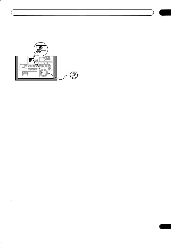
1 Connect the microphone to the MCACC SETUP MIC jack on the rear panel.
MCACC
SETUP MIC
|
|
ANTENNA |
|
MCACC |
|
FM UNBAL 75 |
AM LOOP ANTENNA |
SETUP MIC |
CONTROL IN |
AUDIO INPUT |
|
|
|
DIGITAL |
|
SYSTEM CONNECTOR CONTROL |
SPEAKERS |
DVD/DVR1 |
DVD/DVR2 |
DIGITAL |
ANALOG |
OUT |
SUBWOOFER R SURROUND L |
(COAXIAL) |
(OPTICAL) |
(OPTICAL) |
|
L
R
USE ONLY WITH DISPLAY UNIT.
SEE INSTRUCTION MANUAL.
CENTER R FRONT L
AC IN
2 Place the microphone at your normal listening position.
Place it about ear height, and make sure it is level by using a table or chair.
Make sure there are no obstacles between the speakers and the microphone.
3If the receiver subwoofer is off, press RECEIVER to turn the power on.
4Press MCACC.
Try to be as quiet as possible after pressing MCACC. The volume increases automatically and the system outputs a series of test tones.
•To cancel Auto MCACC setup before it has finished, press MCACC. The unit will continue to use the previous settings.
•If the ambient noise level is too high, NOISY blinks in the display for five seconds. To exit and check the noise levels1, press MCACC, or to try again, press ENTER when RETRY shows in the display.
•If you see an ERR MIC or ERR SP message in the display, there may be a problem with your mic or the speaker connections. To try again, press ENTER when you see RETRY2.
When the MCACC setup is complete, the volume level returns to normal, COMPLETE3 shows in the display, and Acoustic Calibration EQ is activated.4
 Note
Note
1• If the room environment is not optimal for the Auto MCACC setup (too much ambient noise, echo off the walls, obstacles blocking the speakers from the microphone) the final settings may be incorrect. Check for household appliances (air conditioner, fridge, fan, etc.), that may be affecting the environment and switch them off if necessary.
• Some older TVs may interfere with the operation of the mic. If this seems to be happening, switch off the TV during Auto MCACC setup.
2If this doesn’t work, press MCACC, turn off the power, and check the problem indicated by the ERR message, then try the Auto MCACC setup again.
3If COMPLETE doesn’t appear, it is likely an error occurred during the setup. Please check all connections and try again.
4See Listening with Acoustic Calibration EQ on page 28 to switch on/off Acoustic Calibration EQ.
25
En
06 Listening to your system
Chapter 6
Listening to your system
 Important
•To access green functions on the remote, move the slider switch from MAIN to SUB.
Auto listening mode
The Auto listening mode is the simplest way to listen to any source as it was mastered: the output from the speakers mirrors the channels in the source material.
If you set up the system for Front surround (page 6), the Front Surround modes will give the best results (see
Using Front Stage Surround Advance on page 27).
7 |
8 |
9 |
|
SURROUND |
ADVANCED |
SOUND |
MENU |
|
0 |
|
|
SLEEP |
|
CLEAR |
JUKEBOX |
|
|
|
|
INPUT |
CHANNEL |
VOLUME |
DISPLAY |
|
TEXT |
TV/DVD |
RDS DISP |
|
TV CONTROL |
|
|
MAIN |
SUB |
|
|
• Press SURROUND to select the AUTO listening mode.
If the source is Dolby Digital or DTS, the front panel 2 D or DTS indicator lights.
•You can also use the SURROUND button on the display unit to change the listening mode.
Listening in surround sound
You can listen to stereo or multichannel sources in surround sound. Surround sound is generated from stereo sources using one of the Dolby Pro Logic decoding modes.
If you set up the system for Front surround (page 6), the Front Surround modes will give the best results (see
Using Front Stage Surround Advance on page 27).
7 |
8 |
9 |
|
SURROUND |
ADVANCED |
SOUND |
MENU |
|
0 |
|
|
SLEEP |
|
CLEAR |
JUKEBOX |
|
|
|
|
INPUT |
CHANNEL |
VOLUME |
DISPLAY |
|
TEXT |
TV/DVD |
RDS DISP |
|
TV CONTROL |
|
|
MAIN |
SUB |
|
|
The choices that appear in the display will vary according to the type of source that’s playing.
If the source is Dolby Digital or DTS, the front panel 2 D or DTS indicator lights.
•AUTO – Auto listening mode (see above)
•DOLBY PL (Dolby Pro Logic) – 4.1 channel surround sound for use with any two-channel source
•MOVIE (Dolby Pro Logic II Movie) – 5.1 channel surround sound, especially suited to movie sources, for use with any two-channel source
•MUSIC (Dolby Pro Logic II Music) – 5.1 channel surround sound, especially suited to music sources, for use with any two-channel source; see Dolby Pro Logic II Music settings below
•STEREO – See Listening in stereo on page 27.
Dolby Pro Logic II Music settings
When listening in Dolby Pro Logic II Music mode (see above), there are three settings you can adjust: Center Width, Dimension, and Panorama.
SETUP |
/ TUNE+ |
SR + ONETOUCHCOPY |
|
|
|
|
|
|
|
|
|
||||
1 |
2 |
3 |
|
INPUT |
CHANNEL |
VOLUME |
DISPLAY |
/ ST- |
ENTER |
/ ST+ PAUSE LIVE TV |
|
|
|
|
|
4 |
5 |
6 |
|
|
TEXT |
TV/DVD |
RDS DISP |
F. S. SURR |
/ TUNE- TEST TONE |
VIDEO IN |
|
TV CONTROL |
|
||
7 |
8 |
9 |
|
MAIN |
SUB |
|
|
SURROUND |
ADVANCED |
SOUND |
MENU |
|
|
|
|
|
0 |
|
|
|
|
|
|
SLEEP |
|
CLEAR |
JUKEBOX |
|
|
|
|
1With Dolby Pro Logic II Music mode active, press SOUND.
2Use / to select C WIDTH, DIMEN. or
PANORAMA then press ENTER.
•C WIDTH (Center Width) – Provides a better blend of the front speakers by spreading the center channel between the front right and left speakers, making it sound wider (higher settings) or narrower (lower settings).
•DIMEN. (Dimension) – Adjusts the depth of the surround sound balance from front to back, making the sound more distant (minus settings), or more forward (positive settings).
•PANORAMA – Extends the front stereo image to include the surround speakers for a ‘wraparound’ effect.
3Use / to adjust the setting then press ENTER to confirm.
• Press SURROUND repeatedly to select a listening mode.
26 |
• You can also use the SURROUND button on the |
|
display unit to change the listening mode. |
||
|
En
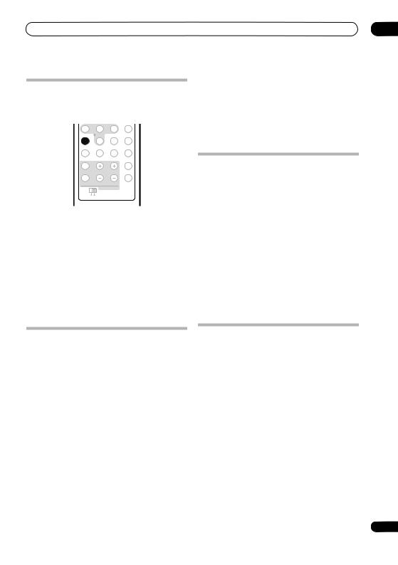
Listening to your system
Using Front Stage Surround Advance
The Front Stage Surround Advance modes are effective when you are using the Front surround speaker setup as described on page 6.
4 |
5 |
6 |
|
F. S. SURR |
/ TUNE- TEST TONE |
VIDEO IN |
|
7 |
8 |
9 |
|
SURROUND |
ADVANCED |
SOUND |
MENU |
|
0 |
|
|
SLEEP |
|
CLEAR |
JUKEBOX |
|
|
|
|
INPUT |
CHANNEL |
VOLUME |
DISPLAY |
|
TEXT |
TV/DVD |
RDS DISP |
|
TV CONTROL |
|
|
MAIN |
SUB |
|
|
• Press F.S.SURR to select a Front Stage Surround Advance mode.
Press repeatedly to select FOCUS5.1, WIDE5.1 or
EXTRAPWR.
•FOCUS5.1 – Use to provide a rich surround sound effect directed to the center area where the left and right speakers’ sound projection converges.
•WIDE5.1 – Use to provide a surround sound effect to a wider area than FOCUS5.1 mode.
•EXTRAPWR – Outputs stereo sound (in the case of multi-channel sources, down-mixed stereo sound) from the surround speakers for powerful stereo effect.
06
•TV SURR. – Surround sound for mono or stereo TV broadcasts
•SPORTS – Suitable for sports programming
•ADV.GAME – Suitable for TV game units
•VIRTUAL – A virtual surround effect using just the subwoofer and front speakers.
•X-STEREO – Powerful surround sound for stereo music sources
Listening in stereo
You can listen to any source — stereo or multichannel — in stereo. When playing a multichannel source, all channels are downmixed to the front left/right speakers and the subwoofer.
F. S. SURR |
/ TUNE- TEST TONE |
VIDEO IN |
|
7 |
8 |
9 |
|
SURROUND |
ADVANCED |
SOUND |
MENU |
|
0 |
|
|
SLEEP |
|
CLEAR |
JUKEBOX |
|
|
|
|
INPUT |
CHANNEL |
VOLUME |
DISPLAY |
|
TEXT |
TV/DVD |
RDS DISP |
|
TV CONTROL |
|
|
MAIN |
SUB |
|
|
• Press SURROUND repeatedly until STEREO shows in the display.
•You can also use the SURROUND button on the display unit to change the listening mode.
Using Advanced Surround
The Advanced Surround effects can be used with any multichannel or stereo source for a variety of additional surround sound effects. These modes are designed to provide optimum listening effect when using the Standard surround setup described on page 8.
SURROUND |
ADVANCED |
SOUND |
MENU |
|
0 |
|
|
SLEEP |
|
CLEAR |
JUKEBOX |
|
|
|
|
INPUT |
CHANNEL |
VOLUME |
DISPLAY |
|
TEXT |
TV/DVD |
RDS DISP |
|
TV CONTROL |
|
|
MAIN |
SUB |
|
|
• Press ADVANCED to select an Advanced Surround mode.
Press repeatedly to select:
•ACTION – Suitable for action movies
•UNPLUGED – Suitable for acoustic musical sources
•EXPANDED – Wide sound field
Using the Sound Retriever
When audio data is removed during the MP3 or WMA compression process, sound quality often suffers from an uneven sound image. The Sound Retriever feature employs new DSP technology that helps bring CD quality sound back to compressed 2-channel audio by restoring sound pressure and smoothing jagged artifacts left over after compression.
 Tip
Tip
•This feature is effective when used together with the Jukebox function of the HDD/DVD recorder.
RECORDER |
RECEIVER |
SOUND
HDD/DVD FM/AM AUDIO IN RETRIEVER
PAUSE |
PLAY |
STOP |
|
|
|
REC |
STOP REC HELP |
INFO |
|
|
|
27
En
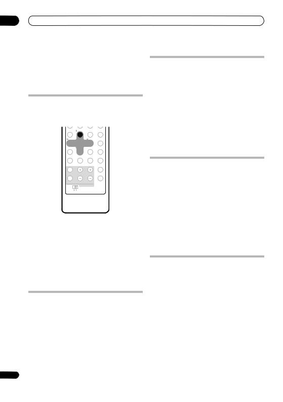
06Listening to your system
•While listening to a stereo source, press SOUND RETRIEVER.
Press repeatedly to switch between:
•RTRV ON — Switches the Sound Retriever on.
•RTRV OFF — Switches the Sound Retriever off.
Listening with Acoustic Calibration EQ
You can listen to sources using the Acoustic Calibration EQ set in Using the Auto MCACC setup for optimal surround sound on page 24.
SETUP |
/ TUNE+ |
SR + ONETOUCHCOPY |
|
1 |
2 |
3 |
|
/ ST- |
ENTER |
/ ST+ PAUSE LIVE TV |
|
4 |
5 |
6 |
|
F. S. SURR |
/ TUNE- TEST TONE |
VIDEO IN |
|
7 |
8 |
9 |
|
SURROUND |
ADVANCED |
SOUND |
MENU |
|
0 |
|
|
SLEEP |
|
CLEAR |
JUKEBOX |
|
|
|
|
INPUT |
CHANNEL |
VOLUME |
DISPLAY |
|
TEXT |
TV/DVD |
RDS DISP |
|
TV CONTROL |
|
|
MAIN |
SUB |
|
|
1Press SOUND.
2Use the / buttons to select MCACC EQ then press ENTER.
3Use the / buttons to switch EQ ON or EQ OFF then press ENTER to confirm.
•On the EQ OFF setting, equalization is set to off and speaker settings (channel delay and channel level) remains as it is set.
•Acoustic Calibration EQ is set to on automatically after Auto MCACC setup is used.
Enhancing dialogue
The Dialogue Enhancement feature is designed to make the dialogue stand out from other background sounds in a TV or movie sound track.
1Press SOUND.
2Use the / buttons to select DIALOGUE then press ENTER.
3Use the / buttons to select the amount dialogue enhancement then press ENTER to confirm.
Select between OFF, MID or MAX.
28
Using Quiet and Midnight listening modes
The Quiet listening feature reduces excessive bass or treble in a sound source.
The Midnight listening feature allows you to hear effective surround sound of movies at low volume levels.
1Press SOUND.
2Use the / buttons to select TONE then press
ENTER.
3Use the /buttons to select QUIET or MIDNIGHT then press ENTER to confirm.
•To cancel the Quiet or Midnight listening modes, select BASS/TRE.
Adjusting the bass and treble
Use the bass and treble controls to adjust the overall tone.
1Press SOUND.
2Use the / buttons to select TONE then press
ENTER.
3Use the / buttons to select BASS/TRE then press ENTER.
•Selecting BASS/TRE cancels the Quiet and Midnight listening modes. These modes cannot be used at the same time.
4Use the / buttons to select BASS or TREBLE; use the / buttons to adjust the sound then press
ENTER to confirm.
Boosting the bass level
There are two bass modes you can use to enhance the bass in a source.
1Press SOUND.
2Use the / buttons to select BASSMODE then press ENTER.
3Use the / buttons to select the sound then press ENTER to confirm.
Select between OFF, MUSIC or CINEMA.
En
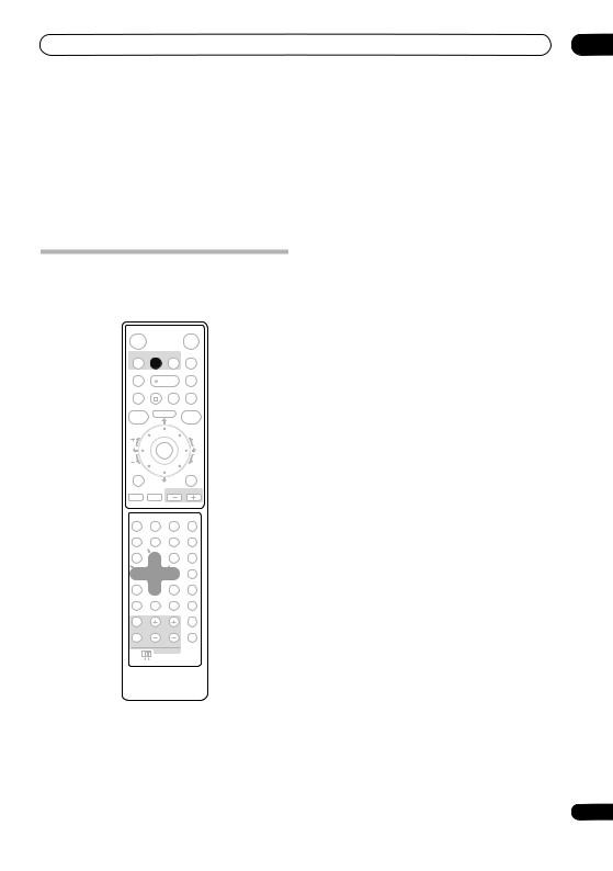
Listening to the radio |
07 |
Chapter 7
Listening to the radio
 Important
•To access green functions on the remote, move the slider switch from MAIN to SUB.
Listening to the radio
The tuner can receive both FM and AM broadcasts, and lets you memorize your favorite stations so you don’t have to manually tune in every time you want to listen.
RECORDER |
RECEIVER |
SOUND
HDD/DVD FM/AM AUDIO IN RETRIEVER
PAUSE |
PLAY |
STOP |
•Manual tuning – Press TUNE +/– repeatedly to change the displayed frequency.
•Auto tuning – Press and hold TUNE +/– until the frequency display starts to move, then release. The tuner will stop on the next station it finds. Repeat to keep searching.
•High-speed tuning – Press and hold TUNE +/– until the frequency display starts to move rapidly. Keep the button held down until you reach the frequency you want. If necessary, fine tune the frequency using the manual tuning method.
Improving poor FM reception
If you’re listening to an FM station in stereo but the reception is weak, you can improve the sound quality by switching to mono.
REC |
STOP REC |
HELP |
INFO |
|
|
|
|
TOP MENU |
|
|
|
DISC |
HOME MENU |
GUIDE |
|
NAVIGATOR |
|
|
|
CHANNEL |
|
|
CM BACK |
|
ENTER |
|
|
CHANNEL |
|
|
CM SKIP |
A.TV/ D.TV |
|
|
RETURN/EXIT |
PREV |
NEXT |
VOLUME |
|
|
|
|
|
AUDIO |
SUBTITLE |
ANGLE |
MCACC |
/ / |
TIMER REC |
REC MODE |
|
SETUP |
/ TUNE+ |
SR + ONETOUCHCOPY |
|
1 |
2 |
3 |
|
/ ST- |
ENTER |
/ ST+ PAUSE LIVE TV |
|
4 |
5 |
6 |
|
F. S. SURR |
/ TUNE- TEST TONE |
VIDEO IN |
|
7 |
8 |
9 |
|
SURROUND |
ADVANCED |
SOUND |
MENU |
1Tune to an FM radio station then press SETUP.
2Use the / buttons to choose FM MODE then press ENTER.
3Use the / buttons to select FM MONO then press ENTER.
The mono indicator ( ) lights when the tuner is in mono reception mode.
Select FM AUTO above to switch back to auto-stereo mode (the stereo indicator ( ) lights when receiving a stereo broadcast).
Improving poor AM sound
The simplest way to improve the sound quality of AM radio is to make sure that the TV in the room is switched off. Also try changing the position and direction of the AM loop antenna.
0
SLEEP |
CLEAR |
JUKEBOX |
|
|
|
INPUT CHANNEL |
VOLUME |
DISPLAY |
TEXT |
TV/DVD |
RDS DISP |
TV CONTROL |
|
|
MAIN 
 SUB
SUB
Changing the noise cut mode
If you find that the sound quality is bad even after trying the above, you may be able to improve it using a different noise cut mode. Just choose the one that sounds best.
|
1 |
Tune to an AM radio station then press SETUP. |
|
2 |
Use the / buttons to choose NOISECUT then |
|
press ENTER. |
|
1 Press FM/AM to switch to the tuner, then press |
3 |
Use the / buttons to select a Noise cut mode |
repeatedly to select the FM or AM band. |
(1, 2 or 3) then press ENTER. |
|
The display shows the band and frequency.
2 Tune to a frequency.
There are three tuning modes — manual, auto, and highspeed:
29
En
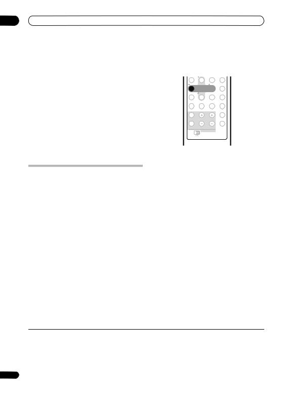
07 Listening to the radio
Memorizing stations
You can save up to 30 station presets so that you always have easy access to your favorite stations without having to tune in manually each time.
1 Tune to an AM or FM radio station.
Select mono or auto-stereo reception (FM) or the Noise Cut mode (AM) as necessary. These settings are saved along with the preset.
2Press SETUP.
3Use the / buttons to choose ST.MEM. then press ENTER.
4Use the / buttons to select the station preset you want then press ENTER.
Listening to station presets
Displaying RDS information
You can display the different types of RDS information available.2
1 |
2 |
3 |
|
/ ST- |
ENTER |
/ ST+ PAUSE LIVE TV |
|
4 |
5 |
6 |
|
F. S. SURR |
/ TUNE- TEST TONE |
VIDEO IN |
|
7 |
8 |
9 |
|
SURROUND |
ADVANCED |
SOUND |
MENU |
|
0 |
|
|
SLEEP |
|
CLEAR |
JUKEBOX |
|
|
|
|
INPUT |
CHANNEL |
VOLUME |
DISPLAY |
|
TEXT |
TV/DVD |
RDS DISP |
|
TV CONTROL |
|
|
MAIN |
SUB |
|
|
1Make sure the tuner function is selected.
2Use the ST +/– buttons to select a station preset.
Using RDS
Radio Data System (RDS) is a system used by most FM radio stations to provide listeners with various kinds of information — the name of the station and the kind of show they’re broadcasting, for example.
One feature of RDS is that you can search by type of program. For example, you can search for a station that’s broadcasting a show with the program type, JAZZ.
You can search the following program types:1
• Press RDS DISP for RDS information.
Each press changes the display as follows:
•Radio Text (RT) – Messages sent by the radio station. For example, a talk radio station may provide a phone number as RT.
•Program Service Name (PS) – The name of the radio station.
•Program Type (PTY) – This indicates the kind of program currently being broadcast.
•SEARCH – PTY search (see below)
•Current tuner frequency
NEWS – News |
FINANCE – Stock market reports, |
Searching for RDS programs |
|
AFFAIRS – Current Affairs |
commerce, trading, etc. |
You can search for a program type listed above. |
|
INFO – General Information |
CHILDREN – Programs for |
1 Press the FM/AM button for the FM band.3 |
|
SPORT – Sport |
children |
||
EDUCATE – Educational |
SOCIAL – Social affairs |
|
|
DRAMA – Radio plays, etc. |
RELIGION – Programs |
2 Press RDS DISP repeatedly until SEARCH appears in |
|
CULTURE – National or regional |
concerning religion |
the display. |
|
culture, theater, etc. |
PHONE IN – Public expressing |
|
|
SCIENCE – Science and |
their views by phone |
3 Use the / buttons to select the program type |
|
technology |
TRAVEL – Holiday-type travel |
you want to hear. |
|
VARIED – Usually talk-based |
rather than traffic |
||
|
|||
material, such as quiz shows or |
announcements |
4 Press ENTER to start the search. |
|
interviews |
LEISURE – Leisure interests and |
The system searches the station presets for a match. If it |
|
POP M – Pop music |
hobbies |
||
finds one, searching stops for five sec. |
|||
ROCK M – Rock music |
JAZZ – Jazz |
||
|
|||
EASY M – Easy listening |
COUNTRY – Country music |
5 If you want to keep listening to the station, press |
|
LIGHT M – ‘Light’ classical music |
NATION M – Popular music in a |
||
ENTER within the five seconds. |
|||
CLASSICS – ‘Serious’ classical |
language other than English |
||
music |
OLDIES – Popular music from the |
If you don’t press ENTER, searching resumes. |
|
OTHER M – Music not fitting |
’50s and ’60s |
|
|
above categories |
FOLK M – Folk music |
|
|
WEATHER – Weather reports |
DOCUMENT – Documentary |
|
 Note
Note
1 In addition, there are three other program types, TEST, ALARM, and NO TYPE. ALARM and TEST are used for emergency announcements. You can’t search for these, but the tuner will switch automatically to this RDS broadcast signal. NO TYPE appears when a program type cannot be found.
2 • If any noise is picked up while displaying the RT scroll, some characters may be displayed incorrectly.
•If you see NO RADIO TEXT DATA in the RT display, it means no RT data is sent from the broadcast station. The display will automatically switch to the PS data display (if no PS data, the frequency is displayed).
•In the PTY display, NO DATA or NO TYPE may be shown. In this case, the PS display is shown after a few seconds.
3 RDS is only possible in the FM band.
30
En
 Loading...