


PLASMA DISPLAY
PRO-1000HDI PRO-800HDI
Register Your Product on
www.pioneerelectronics.com
Operating Instructions

Safety Precautions
CAUTION: WHEN POSITIONING THIS EQUIPMENT
ENSURE THAT THE MAINS PLUG AND SOCKET IS EASILY ACCESSIBLE.
WARNING:
Handling the cord on this product or cords associated with accessories sold with the product will expose you to lead, a chemical known to the State of California and other governmental entities to cause cancer and birth defects or other reproductive harm.
Wash hands after handling.
The following symbols are found on labels attached to the product. They alert the operators and service personnel of this equipment to any potentially dangerous conditions.
 WARNING
This symbol refers to a hazard or unsafe practice which can result in personal injury or property damage.
 CAUTION
This symbol refers to a hazard or unsafe practice which can result in severe personal injury or death.
IMPORTANT NOTICE
The serial number for this equipment is located on the rear panel. Please write this serial number on your enclosed warranty card and keep it in a secure area. This is for your security.
ii
PRO-1000HDI / PRO-800HDI
Safety Precautions
IMPORTANT SAFETY INSTRUCTIONS
READ INSTRUCTIONS — All the safety and operating |
GROUNDING OR POLARIZATION |
OBJECT AND LIQUID ENTRY — Never push objects |
instructions should be read before the product is |
÷ If this product is equipped with a polarized |
of any kind into this product through openings as |
operated. |
alternating current line plug (a plug having one |
they may touch dangerous voltage points or short- |
RETAIN INSTRUCTIONS — The safety and operating |
blade wider than the other), it will fit into the outlet |
out parts that could result in a fire or electric shock. |
instructions should be retained for future |
only one way. This is a safety feature. If you are |
Never spill liquid of any kind on the product. |
reference. |
unable to insert the plug fully into the outlet, try |
SERVICING — Do not attempt to service this product |
HEED WARNINGS — All warnings on the product and |
reversing the plug. If the plug should still fail to fit, |
yourself as opening or removing covers may |
in the operating instructions should be adhered to. |
contact your electrician to replace your obsolete |
expose you to dangerous voltage or other hazards. |
FOLLOW INSTRUCTIONS — All operating and use |
outlet. Do not defeat the safety purpose of the |
Refer all servicing to qualified service personnel. |
instructions should be followed. |
polarized plug. |
DAMAGE REQUIRING SERVICE — Unplug this |
CLEANING — Unplug this product from the wall outlet |
÷ If this product is equipped with a three-wire |
product from the wall outlet and refer servicing to |
before cleaning. The product should be cleaned |
grounding type plug, a plug having a third |
qualified service personnel under the following |
only with a polishing cloth or a soft dry cloth. Never |
(grounding) pin, it will only fit into a grounding type |
conditions: |
clean with furniture wax, benzine, insecticides or |
power outlet. This is a safety feature. If you are |
÷ When the power-supply cord or plug is damaged. |
other volatile liquids since they may corrode the |
unable to insert the plug into the outlet, contact |
÷ If liquid has been spilled, or objects have fallen |
cabinet. |
your electrician to replace your obsolete outlet. Do |
into the product. |
ATTACHMENTS — Do not use attachments not |
not defeat the safety purpose of the grounding |
÷ If the product has been exposed to rain or water. |
recommended by the product manufacturer as |
type plug. |
÷ If the product does not operate normally by |
they may cause hazards. |
POWER-CORD PROTECTION — Power-supply cords |
following the operating instructions. Adjust only |
WATER AND MOISTURE — Do not use this product |
should be routed so that they are not likely to be |
those controls that are covered by the operating |
near water — for example, near a bathtub, wash |
walked on or pinched by items placed upon or |
instructions as an improper adjustment of other |
bowl, kitchen sink, or laundry tub; in a wet |
against them, paying particular attention to cords |
controls may result in damage and will often |
basement; or near a swimming pool; and the like. |
at plugs, convenience receptacles, and the point |
require extensive work by a qualified technician to |
ACCESSORIES — Do not place this product on an |
where they exit from the product. |
restore the product to its normal operation. |
unstable cart, stand, tripod, bracket, or table. The |
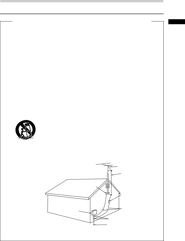
OUTDOOR ANTENNA GROUNDING — If an outside |
÷ If the product has been dropped or damaged in |
product may fall, causing serious injury to a child |
antenna or cable system is connected to the |
any way. |
or adult, and serious damage to the product. Use |
product, be sure the antenna or cable system is |
÷ When the product exhibits a distinct change in |
only with a cart, stand, tripod, bracket, or table |
grounded so as to provide some protection against |
performance — this indicates a need for service. |
recommended by the manufacturer, or sold with |
voltage surges and built-up static charges. Article |
REPLACEMENT PARTS — When replacement parts |
the product. Any mounting of the product should |
810 of the National Electrical Code, ANSI/NFPA |
are required, be sure the service technician has |
follow the manufacturer’s instructions, and should |
70, provides information with regard to proper |
used replacement parts specified by the |
use a mounting accessory recommended by the |
grounding of the mast and supporting structure, |
manufacturer or have the same characteristics as |
manufacturer. |
grounding of the lead-in wire to an antenna |
the original part. Unauthorized substitutions may |
CART — A product and cart combination should be |
discharge unit, size of grounding conductors, |
result in fire, electric shock, or other hazards. |
moved with care. Quick stops, excessive force, |
location of antenna-discharge unit, connection to |
SAFETY CHECK — Upon completion of any service |
and uneven surfaces may cause the product and |
grounding electrodes, and requirements for the |
or repairs to this product, ask the service technician |
cart combination to overturn. |
grounding electrode. See Figure A. |
to perform safety checks to determine that the |
|
LIGHTNING — For added protection for this product |
product is in proper operating condition. |
|
during a lightning storm, or when it is left |
HEAT — The product should be situated away from |
|
unattended and unused for long periods of time, |
heat sources such as radiators, heat registers, |
|
unplug it from the wall outlet and disconnect the |
stoves, or other products (including amplifiers) that |
|
antenna or cable system. This will prevent damage |
produce heat. |
|
to the product due to lightning and power-line |
WALL OR CEILING MOUNTING — The product |
|
surges. |
should be mounted to a wall or ceiling only as |
|
POWER LINES — An outside antenna system should |
recommended by the manufacturer. |
|
not be located in the vicinity of overhead power |
|
|
lines or other electric light or power circuits, or |
|
VENTILATION — Slots and openings in the cabinet |
where it can fall into such power lines or circuits. |
|
are provided for ventilation and to ensure reliable |
When installing an outside antenna system, |
|
operation of the product and to protect it from |
extreme care should be taken to keep from |
|
overheating, and these openings must not be |
touching such power lines or circuits as contact |
|
blocked or covered. The openings should never |
with them might be fatal. |
|
be blocked by placing the product on a bed, sofa, |
OVERLOADING — Do not overload wall outlets, |
|
rug, or other similar surface. This product should |
extension cords, or integral convenience |
|
not be placed in a built-in installation such as a |
receptacles as this can result in a risk of fire or |
|
bookcase or rack unless proper ventilation is |
electric shock. |
|
provided or the manufacturer’s instructions have |
|
|
been adhered to. |
|
|
POWER SOURCES — This product should be operated |
|
|
only from the type of power source indicated on |
|
ANTENNA |
the marking label. If you are not sure of the type |
|
LEAD IN |
of power supply to your home, consult your |
|
|
|
WIRE |
|
product dealer or local power company. |
|
|
LOCATION — The appliance should be installed in a |
|
|
stable location. |
GROUND |
|
NONUSE PERIODS — The power cord of the |
|
|
appliance should be unplugged from the outlet |
CLAMP |
|
when left unused for a long period of time. |
|
|
|
ANTENNA |
|
|
DISCHARGE UNIT |
|
|
(NEC SECTION 810-20) |
|
ELECTRIC |
GROUNDING CONDUCTORS |
|
SERVICE |
||
(NEC SECTION 810-21) |
||
EQUIPMENT |
||
|
||
|
GROUND CLAMPS |
|
Figure A |
POWER SERVICE GROUNDING |
|
|
||
|
ELECTRODE SYSTEM |
|
|
(NEC ART 250, PART H) |
|
|
NEC – NATIONAL ELECTRICAL CODE |
iii
Safety Precautions
PRO-1000HDI / PRO-800HDI
Safety Precautions
FEDERAL COMMUNICATIONS COMMISSION
DECLARATION OF CONFORMITY
This device complies with part 15 of the FCC Rules. Operation is subject to the following two conditions: (1) This device may not cause harmful interference, and (2) this device must accept any interference received, including interference that may cause undesired operation.
Product Name: Plasma Display
Model Number: PRO-1000HDI / PRO-800HDI
Product Category: Class B Personal Computers & Peripherals
Responsible Party Name: PIONEER ELECTRONICS [USA] INC. Customer Support Division Address: P.O. BOX 1760, LONG BEACH, CA., 90801-1760 U.S.A.
Phone: (800)421-1625
URL http://www.Pioneerelectronics.com
Please do not ship your product to Pioneer without first calling the Customer Support Division at the above listed number for assistance.


Pioneer Electronics [USA] Inc. 
Customer Support Division 

P. O. BOX 1760, Long Beach,
CA 90801-1760, U.S.A.
iiiv
PRO-1000HDI / PRO-800HDI

|
|
Thank you very much for purchasing this PIONEER |
|
|
Notes on Installation Work: |
||
|
This product is marketed assuming that it is installed by qualified |
product. |
|
|
Before using your Plasma Display, please carefully read |
||
|
personnel with enough skill and competence. Always have an |
||
|
installation specialist or your dealer install and set up the product. |
the “Safety Precautions” and these “Operating |
|
|
PIONEER cannot assume liabilities for damage caused by |
Instructions” so you will know how to operate the |
|
|
mistake in installation or mounting, misuse, modification or a |
||
|
Plasma Display properly. Keep this manual in a safe |
||
|
natural disaster. |
||
|
|
place. You will find it useful in the future. |
|
|
|
||
|
|
|
|
|
Note for Dealers: |
|
|
|
After installation, be sure to deliver this manual to the customer |
|
|
|
and explain to the customer how to handle the product. |
|
|
|
|
|
|
|
|
|
|
|
|
|
|
Contents
Before Proceeding
Safety Precautions ................................. |
i |
Before Proceeding ................................. |
2 |
How to Use This Manual ......................................... |
2 |
Checking Supplied Accessories .............................. |
3 |
Part Names and Functions ................... |
4 |
Main Unit .................................................................. |
4 |
Remote Control Unit ................................................ |
5 |
Connection Panel ..................................................... |
6 |
Installation and Connections ............... |
8 |
Installation of the Unit ............................................. |
8 |
About the Input Connectors on this Unit ............... |
9 |
Connection to INPUT1 and INPUT2 ....................... |
9 |
Connection to INPUT3 ........................................... |
13 |
Connection to INPUT4 ........................................... |
13 |
Connection to INPUT5 ........................................... |
13 |
About DTV Set Top Box Connection .................... |
14 |
Audio Connections ................................................ |
14 |
Control Cord Connection ...................................... |
16 |
Power Cord Connection ........................................ |
16 |
How to Route Cables ............................................. |
17 |
Setting Up the System ....................... |
18 |
Setup after Connection (INPUT1, 2) ..................... |
18 |
Setup after Connection (INPUT5) ......................... |
20 |
Operations ........................................... |
22 |
Selecting an Input Source ..................................... |
22 |
Screen Size Selection ............................................ |
24 |
Partial Image Enlargement (POINT ZOOM) ......... |
25 |
Automatic Power OFF ........................................... |
26 |
Display Panel Adjustments ................ |
27 |
Adjusting the Picture Quality ................................ |
27 |
Adjusting the Image Position and Clock |
|
(Automatic Adjustment) ....................................... |
28 |
Manual Adjustment of Screen Position and |
|
Clock ...................................................................... |
28 |
Other Operations ................................ |
30 |
Rewriting the Input Display (INPUT LABEL) ........ |
30 |
Changing the Color Temperature |
|
(COLOR TEMP) ...................................................... |
31 |
Reducing Video Noise (DIGITAL NR) .................... |
31 |
Setting the PureCinema mode ............................. |
32 |
Viewing a Fast Moving Picture |
|
(3D Y/C MODE) ...................................................... |
32 |
Viewing in a Bright Location |
|
(HIGH CONTRAST) ................................................ |
33 |
Power Control Function ........................................ |
33 |
AUTO FUNCTION .................................................. |
34 |
Audio Output (AUDIO OUT) .................................. |
34 |
Additional Information ....................... |
35 |
Cleaning .................................................................. |
35 |
Troubleshooting ..................................................... |
35 |
Specifications ......................................................... |
38 |
Supplement 1 ......................................................... |
39 |
Supplement 2 ......................................................... |
41 |
Supplement 3 ......................................................... |
41 |
Supplement 4 ......................................................... |
42 |
Explanation of Terms ............................................. |
42 |
1
PRO-1000HDI / PRO-800HDI
Before Proceeding
How to Use This Manual
This manual is set up to follow the course of actions and operations in the order that would seem most logical for someone setting up this unit.
Once the unit has been taken out of the box, and it has been confirmed that all the parts have been received, it may be beneficial to look over the section “Part Names and Functions” starting on page 4 to become acquainted with the plasma monitor and remote control unit, as their respective buttons and controls will be referred to throughout this manual.
The section “Installation and Connections” starting on page 8 covers all the necessary points regarding installation of the plasma display and connections to a wide variety of components.
The section “Setting Up the System” starting on page 18 covers the necessary on-screen menu settings to establish correct linkage between the plasma display and connected components. Depending on the connections made, this section may or not be necessary.
The remainder of the sections in this manual is dedicated to the basic operations associated with selecting a source component up to the more complex operations associated with adjusting the plasma display picture to match the requirements of specific components and personal preferences.
About operations in this manual
Operations in this manual are outlined in step by step numbered procedures. Most of the procedures are written in reference to the remote control unit unless the button or control is only present on the main unit. However, if a button or control on the main unit has the same or similar name as that on the remote control unit, that button can be used when performing operations.
Note
The screen displays depicted in this manual represent typical display examples.
The actual items and contents seen in screen displays may vary depending on input source and specific settings.
Screen Displays
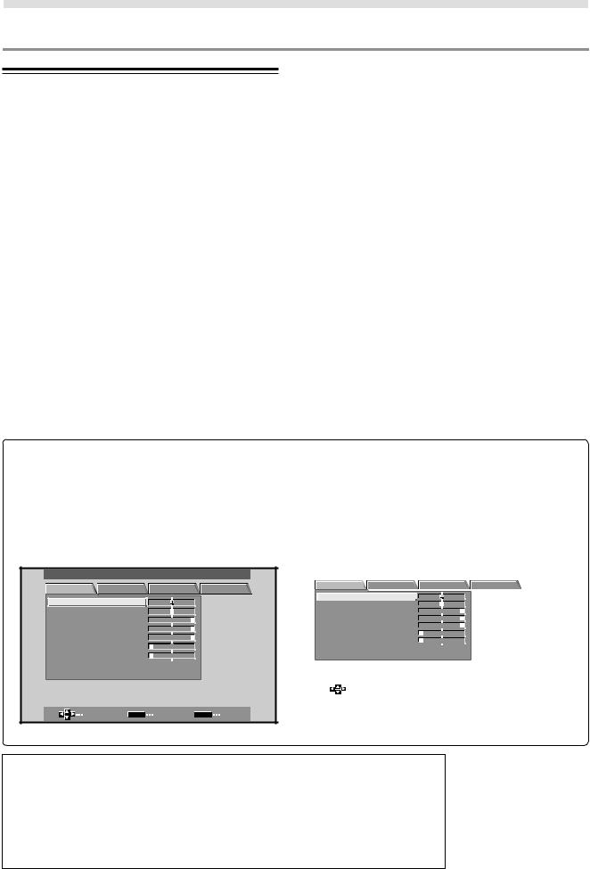
The example screen displays provided in this manual are those for the PRO-1000HDI model. The PRO-800HDI display differs as shown:
Example of PRO-1000HDI Screen Display:
÷The PRO-1000HDI screen display has a nondisplaying border at each side of the display.
MAIN MENU |
|
|
|
|
|
INPUT1 |
PICTURE |
SCREEN |
SET UP |
OPTION |
|||
CO NT RA S T |
|
: |
0 |
|
|
|
BR I GHT . |
|
: |
0 |
|
|
|
R. L E V E L |
|
: + 6 0 |
|
|
|
|
G. L E V E L |
|
: + 6 0 |
|
|
|
|
B. L E V E L |
|
: + 6 0 |
|
|
|
|
H. E NHAN CE |
: |
0 |
|
|
|
|
V . E NHAN CE |
: |
0 |
|
|
|
|
RE S E T |
|
|
|
|
|
|
SELECT |
|
SET |
ENTER |
MENU |
EXIT |
|
Example of PRO-800HDI Screen Display:
÷The PRO-800HDI screen display fills the display area in both horizontal directions.
MAIN MENU |
|
|
|
|
INPUT1 |
PICTURE SCREEN |
SET UP |
OPTION |
|||
C O N T R A S T |
: |
0 |
|
|
|
B R I GH T . |
: |
0 |
|
|
|
R. L E V E L |
: + 6 0 |
|
|
|
|
G. L E V E L |
: + 6 0 |
|
|
|
|
B. L E V E L |
: + 6 0 |
|
|
|
|
H. E NH AN CE |
: |
0 |
|
|
|
V . E NH AN CE |
: |
0 |
|
|
|
RE S E T |
|
|
|
|
|
|
|
|
|
|
|
SELECT |
|
|
ENTER |
|
EXIT |
|
SET |
MENU |
|||
|
|
|
|
|
|
Please note that the actual contents displayed are the same for both the PRO-1000HDI and PRO-800HDI.
Apple and Macintosh are registered trademarks of Apple Computer, Inc.
Microsoft is a registered trademark of Microsoft Corporation.
NEC and PC-9800 are trademarks of NEC Corporation.
VESA and DDC are registered trademarks of Video Electronics Standards Association.
Power Management and Sun Microsystems are registered trademarks of Sun Microsystems, Inc.
VGA and XGA are registered trademarks of International Business Machines Co., Inc. HDMI, the HDMI logo and High-Definition Multimedia Interface are trademarks or registered trademarks of HDMI Licensing LLC.
2
PRO-1000HDI / PRO-800HDI
|
|
|
|
|
|
|
|
|
Before Proceeding |
|
|
|
|
|
|
|
|
|
|
|
|
|
|
|
|
|
|
|
|
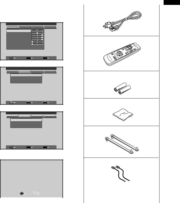
The following example is an actual operation that shows |
Checking Supplied Accessories |
|
|
||
how one might set the horizontal and vertical positions of |
|
|
|
|
|
the screen. The screens shown at each step are provided |
Check that the following accessories were supplied. |
|
|
||
as a visual guide to confirm that the procedure is |
|
|
|
|
|
|
|
|
|
||
proceeding as it should. Please familiarize yourself with this |
|
1 Power cord |
|
|
|
process before continuing on with the rest of this manual. |
|
|
|
|
|
1 Press MENU to display the menu screen.
MAIN MENU |
|
|
|
|
|
|
INPUT1 |
|
PICTURE |
SCREEN |
SET UP |
OPTION |
|
||||
CO NT RA S T |
|
: |
0 |
|
|
|
|
|
BR I GHT . |
|
: |
0 |
|
|
|
|
|
R. L E V E L |
|
: + 6 0 |
|
|
|
|
|
|
G. L E V E L |
|
: + 6 0 |
|
|
|
|
2 Remote control unit |
|
B. L E V E L |
|
: + 6 0 |
|
|
|
|
||
H. E NHAN CE |
: |
0 |
|
|
|
|
|
|
V . E NHAN CE |
: |
0 |
|
|
|
|
|
|
RE S E T |
|
|
|
|
|
|
|
|
SELECT |
|
SET |
ENTER |
|
MENU |
EXIT |
|
|
2 Press 3 to select SCREEN. |
|
|
|
|
||||
MAIN MENU |
|
|
|
|
|
|
INPUT1 |
|
PICTURE |
SCREEN |
SET UP |
OPTION |
3 AA (R6) batteries (x 2) |
||||
P O S I T I O N |
|
: |
0 / |
0 |
|
|
||
CL OC K / PHA S E : |
0 / |
0 |
|
|
|
|||
RE S E T |
|
|
|
|
|
|
|
|
SELECT |
|
SET |
ENTER |
|
MENU |
EXIT |
4 Cleaning cloth (for wiping front panel) |
|
3 Press 5/∞ to select the item to be adjusted. |
|
|||||||
MAIN MENU |
|
|
|
|
|
|
INPUT1 |
|
PICTURE |
SCREEN |
SET UP |
OPTION |
|
||||
P O S I T I O N |
|
: |
0 / |
0 |
|
|
|
|
CL OC K / PHA S E : |
0 / |
0 |
|
|
|
|||
RE S E T |
|
|
|
|
|
|
|
|
|
|
|
|
|
|
|
|
5 Speed clamps (x 2) |
SELECT |
|
SET |
ENTER |
|
MENU |
EXIT |
|
|
4 Press SET to display the adjustment screen for the |
|
|||||||
selected item. |
|
|
|
|
|
|
|
6 Bead bands (x 2) |
|
|
|
|
|
|
|
|
|
|
|
H . P O S I T I O N : |
0 |
|
|
|
|
|
|
|
V . P O S I T I O N : |
0 |
|
|
÷ Operating Instructions |
||
|
|
|
|
|
|
|
||
|
|
|
|
|
|
÷ Warranty |
||
|
|
ADJUST SET |
SET |
|
||||
|
|
|
MENU |
EXIT |
|
|
|
|
|
|
|
|
|
|
|
|
|
|
|
|
|
|
|
|
|
|
5 Press 5/∞/2/3 to adjust the value. |
|
|
||||||
3
Before Proceeding
PRO-1000HDI / PRO-800HDI
Part Names and Functions
Main Unit
Main unit
1
2
Main unit
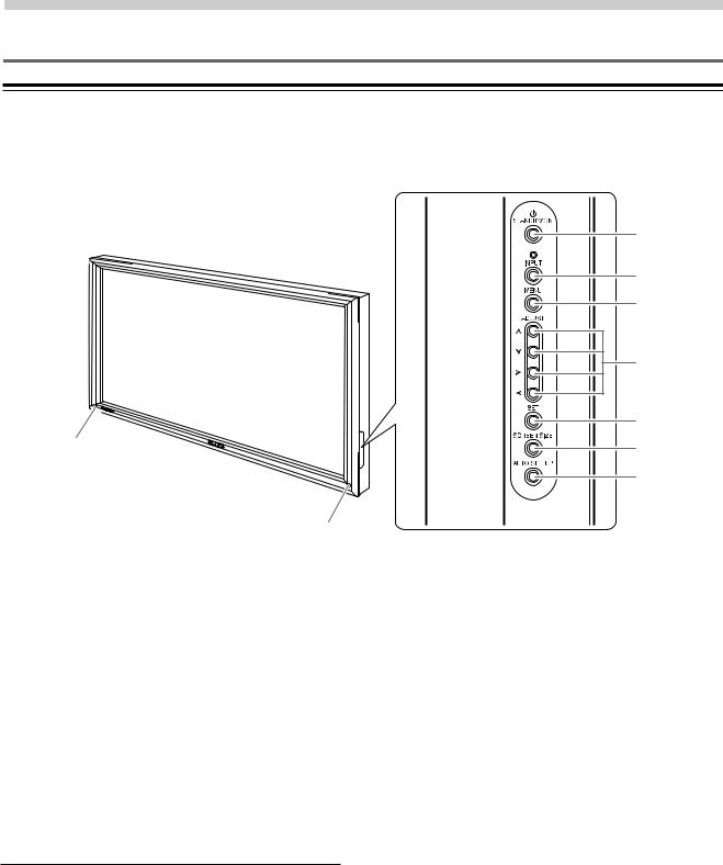
1STANDBY/ON indicator
This indicator is red during standby mode, and turns to green when the unit is in the operation mode (page 22).
Flashes green when Power-Management function is operating (page 26).
The flashing pattern is also used to indicate error messages (page 37).
2Remote control sensor
Point the remote control toward the remote sensor to operate the unit (page 6).
Operation panel on the main unit
3STANDBY/ON button
Press to put the display in operation or standby mode (page 22).
4INPUT button
Press to select input (page 22).
4
Operation panel on the main unit
3
4
5
6 |
7
8
9
5MENU button
Press to open and close the on-screen menu (pages 18 to 34).
6ADJUST (5/∞/3/2) buttons
Use to navigate menu screens and to adjust various settings on the unit.
Usage of cursor buttons within operations is clearly indicated in the on-screen display (pages 18 to 34).
7SET button
Press to adjust or enter various settings on the unit (pages 18 to 34).
8SCREEN SIZE button
Press to select the screen size (page 24).
9AUTO SET UP button
When using computer signal input, automatically sets the POSITION and CLOCK/PHASE to optimum values (page 28).
PRO-1000HDI / PRO-800HDI
Part Names and Functions
Remote Control Unit
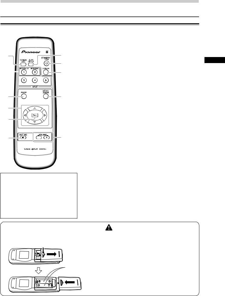
1SCREEN SIZE button
Press to select the screen size (page 24).
1 |
|
|
|
|
|
|
|
|
7 |
2 INPUT buttons |
||
|
|
|
|
|
|
|
|
Use to select the input (page 22). |
||||
|
|
|
|
|
|
|
|
|
|
|
|
|
2 |
|
|
|
|
|
|
|
|
|
|
8 |
3 MENU button |
|
|
|
|
|
|
|
|
|
|
|||
|
|
|
|
|
|
|
|
|
9 |
|||
|
|
|
|
|
|
|
|
|
||||
|
|
|
|
|
|
|
|
|
||||
|
|
|
|
|
|
|
|
|
Press to open and close the on-screen menu |
|||
|
|
|
|
|
|
|
|
|
||||
|
|
|
|
|
|
|
|
|
|
|
|
(pages 18 to 34). |
|
|
|
|
|
|
|
|
|
|
|
|
4 ADJUST (5/∞/3/2) buttons |
|
|
|
|
|
|
|
|
|
|
|
|
|
|
|
|
|
|
|
|
|
|
|
|
|
|
3 |
|
|
|
|
|
|
|
|
0 |
Use to navigate menu screens and to adjust various settings on the |
||
|
|
|
|
|
|
|
|
|||||
|
|
|
|
|
|
|
|
|||||
|
|
|
|
|
|
|
|
unit. |
||||
|
|
|
|
|
|
|
|
|
|
|
|
Usage of cursor buttons within operations is clearly indicated at the |
4 |
|
|
|
|
|
|
|
|
|
|
bottom the on-screen menu display (pages 18 to 34). |
|
|
|
|
|
|
|
|
|
|
|
|
||
5 |
|
|
|
|
|
|
|
|
|
|
5 SET button |
|
|
|
|
|
|
|
|
|
|
|
Press to adjust or enter various settings on the unit (pages 18 to 34). |
||
|
|
|
|
|
|
|
|
|
|
|
|
|
|
|
|
|
|
|
|
|
|
|
|
|
6 MUTING button |
6 |
|
|
|
|
|
|
|
|
- |
Press to mute the volume (page 23). |
||
|
|
|
|
|
|
|
|
|||||
|
|
|
|
|
|
|
|
|||||
|
|
|
|
|
|
|
|
|
||||
7 AUTO SET UP button
When using computer signal input, automatically sets the POSITION and CLOCK/ PHASE to optimum values (page 28).
|
8 STANDBY/ON button |
|
|
Press to put the unit in operation or standby mode (page 22). |
|
When handling the remote control unit |
9 DISPLAY button |
|
¶ Do not drop or shake the remote control. |
Press to view the unit’s current input and setup mode (page 23). |
|
¶ Do not use the remote control unit in a location |
||
|
||
subject to direct sunlight, heat radiation from a |
0 POINT ZOOM button |
|
heater, or in a place subject to excessive |
||
humidity. |
Use to select and enlarge one part of the screen (page 25). |
|
¶ When the remote control unit’s batteries begin |
|
|
to wear out, the operable distance will gradually |
- VOLUME (+/–) buttons |
|
become shorter. When this occurs, replace all |
Use to adjust the volume (page 23). |
|
batteries with new ones as soon as possible. |
||
|
Inserting the batteries in the |
CAUTION |
|
remote control unit |
||
¶ Insert batteries so that the plus (+) and minus (–) sides are |
||
|
||
|
aligned according to the markings in the battery case. |
|
While pressing down lightly, slide |
¶ Do not mix new batteries with used ones. |
|
¶ The voltage of batteries may differ even if they are the same |
||
in the direction of the arrow. |
||
|
shape. Please do not mix different kinds of batteries |
|
|
together. |
|
|
¶ When not using the remote control unit for a long period of |
|
|
time (1 month or more), remove the batteries from the |
|
Two AA (R6) |
remote control unit to prevent leaking of battery fluid. If |
|
battery liquid has leaked, thoroughly wipe the inside of the |
||
batteries |
case until all liquid is removed, and then insert new batteries. |
|
|
¶ Do not charge, short, disassemble or throw the provided |
|
|
batteries in a fire. |
|
|
When disposing of used batteries, please comply with |
|
|
governmental regulations or environmental public |
|
|
instruction’s rules that apply in your country or area. H048 En |
5
Part Names and Functions
PRO-1000HDI / PRO-800HDI

Part Names and Functions
Connection Panel
The connection panel is provided with four video input terminals and two video output terminals. Audio input and speaker output terminals are also provided, together with a CONTROL IN/OUT connector for connecting to PIONEER components bearing the Î mark.
For instructions regarding connections, consult the pages noted in parentheses by each item.
1SPEAKER (R) terminal
For connection of an external right speaker. Connect a speaker whose impedance is 8 –16 Ω
(page 14).
2CONTROL IN/OUT (monaural mini jacks)
For connection of PIONEER components that bear the Î mark. Making CONTROL connection enables control of this unit as a component in a system
(page 16).
3COMBINATION IN/OUT
DO NOT MAKE ANY CONNECTIONS TO THESE TERMINALS.
These terminals are used in the factory setup.
4RS-232C
DO NOT MAKE ANY CONNECTIONS TO THIS TERMINAL.
This terminal is used in the factory setup.
5INPUT1 (mini D-sub 15 pin)
For connection of components that have RGB or component output jacks such as a personal computer, DVD player, or external RGB decoder. Make sure that the connection made corresponds to the format of the signal output from the connected component (pages 9 to 12).
6OUTPUT (INPUT1) (mini D-sub 15 pin)
Use the OUTPUT (INPUT1) terminal to output the video signal to an external monitor or other component.
Note: The video signal will not be output from the OUTPUT (INPUT1) terminal when the main power of this unit is off or in standby mode.
(page 11)
7INPUT2 (BNC jacks)
For connection of components that have RGB or component output jacks such as a personal computer, DVD player, or external RGB decoder. Make sure that the connection made corresponds to the format of the signal output from the connected component (pages 9 to 12).
8Synchronizing signal impedance selector switch
Depending on the connections made at INPUT2, it may be necessary to set this switch to match the output impedance of the connected component’s synchronization signal.
When the output impedance of the component’s synchronization signal is below 75 Ω , set this switch to the 75 Ω position (pages 10, 12).
Operating range of the remote control unit
When operating the remote control unit, point it at the remote sensor (Î) located on the front panel of the main unit. The remote control unit is operable up to 23 feet (7 m) from the unit and within a 30 angle on each side of the sensor.
If you are having difficulty with operation of the remote control unit
¶The remote control unit may not operate if there are objects placed between it and the display.
¶Operational distance will gradually become shorter as the batteries begin to wear out, replace weak batteries with new ones as soon as possible.
¶This unit discharges infrared rays from the screen. Placing a video deck or other component that is operated by an infrared remote control unit near this unit may hamper that component’s reception of the remote control’s signal, or prevent it from receiving the signal entirely. Should this occur, move the component to a position further away from this unit.
¶Depending on the installation surroundings, this unit’s remote control unit may be influenced by the infrared rays discharged from the plasma display, hampering reception of its rays or limiting its operational distance. The strength of infrared rays discharged from the screen will differ according to the picture displayed.
6
7 m
(23 feet)
30˚
30˚
Remote
Sensor
PRO-1000HDI / PRO-800HDI
Part Names and Functions
Illustration depicts |
|
|
|
|
|
|
|
|
|
|
|
|
|
|
|
|
|
PRO-1000HDI model. |
|
|
|
|
|
|
|
|
|
|
|
|
|
|
|
|
|
R |
8Ω |
~16Ω |
|
|
CONTROL |
COMBINATION |
RS-232C |
|
INPUT1 |
(ON SYNC) |
|
INPUT2 (H/V SYNC) |
|
||||
|
|
IN |
OUT |
IN |
OUT |
|
ANALOG RGB |
OUTPUT |
G |
B |
R |
HD |
VD |
||||
SPEAKER |
|
|
|
(ANALOG RGB) |
|
|
|
|
|
|
|||||||
+ |
– |
|
|
|
|
|
|
|
|
|
|
|
|
|
|
|
|
|
1 |
|
|
2 |
|
3 |
4 |
5 |
6 |
|
|
7 |
|
|
|
||
INPUT5 |
|
AUDIO |
AUDIO |
INPUT3 S-VIDEO |
AUDIO |
|
INPUT4 VIDEO |
|
|
AC INLET |
|
|
|
8Ω |
~16Ω |
L |
|
|
|
|
|
|
|
|
|
||||||||||
|
|
R |
L |
R |
L |
R |
L |
|
|
|
|
|
|
|
SPEAKER |
||
HDMI |
|
|
|
|
|
|
|
|
|
|
|
|
|
|
+ |
– |
|
|
|
|
|
|
|
|
|
|
|
|
|
|
|
|
|
|
|
- |
|
= |
~ ! @ |
# |
|
$ |
% |
|
|
|
^ |
|
|||||
AUDIO
INPUT OUTPUT
75Ω Ô2k.Ω2 (INPUT1/2)
89 0
9
0
-
=
~
AUDIO INPUT (Stereo mini jack)
Use to obtain sound when INPUT1 or INPUT2 is selected.
Connect the audio output terminal of components connected to INPUT1 or INPUT2 to this unit (page 15).
AUDIO OUTPUT (Stereo mini jack)
Use to output the audio of the selected source component connected to this unit to an AV amplifier or similar component (page 15).
INPUT5 (HDMI jack)
For connection of components that have a digital video output terminal sach as a digital set top box, DVD player, etc. compatible with HDCP. Before attempting to connect one of these devices, read its operating instructions to make sure that it can be connected (page 13).
(HDCP = High-brandwidth Digital Content Protection) (HDMI = High Definition Multimedia Interface)
AUDIO INPUT5 (RCA Pin jacks)
Use to obtain sound when INPUT5 (analog audio) is selected.
Connect these jacks to the audio output connectors of components connected to INPUT5 (page 15).
Note: The left audio channel (L) jack is not compatible with monaural input sources.
AUDIO INPUT3 (RCA Pin jacks)
Use to obtain sound when INPUT3 is selected. Connect these jacks to the audio output connectors of components connected to INPUT3 (page 15).
Note: The left audio channel (L) jack is not compatible with monaural input sources.
!INPUT3 (S-video jack)
For connection of components that have an S-video output terminal such as a video deck, video camera, LaserDisc player, or DVD player. (page 13)
@AUDIO INPUT4 (RCA Pin jacks)
Use to obtain sound when INPUT4 is selected. Connect these terminals to the audio output connectors of components connected to INPUT4 (page 15).
Note: The left audio channel (L) jack is not compatible with monaural input sources.
#INPUT4 (BNC jack)
For connection of components that have a composite video output terminal such as a video deck, video camera, LaserDisc player, or DVD player (page 13).
$Main power switch
Use to switch the main power of the unit on and off.
%AC INLET
Use to connect the supplied power cord to an AC outlet (page 16).
^SPEAKER (L) terminal
For connection of an external left speaker. Connect a
speaker that has an impedance of 8 –16 Ω (page 14).
7
Part Names and Functions
PRO-1000HDI / PRO-800HDI
Installation and Connections
Installation of the Unit
Installation using the optional PIONEER stand or installation bracket
÷Please be sure to request installation or mounting of this unit or the installation bracket by the dealer where purchased.
÷When installing, be sure to use the bolts provided with the stand or installation bracket.
÷For details concerning installation, please refer to the instruction manual provided with the stand or installation bracket.
Installation using accessories other than the PIONEER stand or installation bracket (sold separately)
÷When possible, please install using parts and accessories manufactured by PIONEER. PIONEER will not be held responsible for accident or damage caused by the use of parts and accessories manufactured by other companies.
÷For custom installation, please consult the dealer where the unit was purchased.
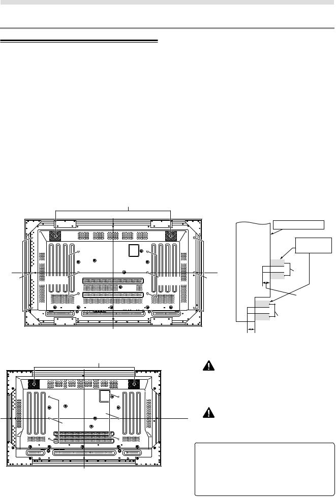
Wall-mount installation of the unit
This unit has been designed with bolt holes for wall-mount installation, etc.. The installation holes that can be used are shown in the diagram below.
÷Be sure to attach in 4 or more locations above and below, left and right of the center line.
÷Use bolts that are long enough to be inserted 1/2 inch (12 mm) to 11/16 inch (18 mm) into the main unit from the attaching surface for both a holes and b holes.
Refer to the side view diagram below.
÷As this unit is constructed with glass, be sure to install it on a flat, unwarped surface.
 CAUTION
To avoid malfunction, overheating of this unit, and possible fire hazard, make sure that the vents on the main unit are not blocked when installing. Also, as hot air is expelled from the air vents, be careful of deterioration and dirt build up on rear surface wall, etc..
 CAUTION
Please be sure to use an M8 (Pitch = 1.25 mm) bolt. (Only this size bolt can be used.)
|
|
|
|
Attaching surface |
|
|
|
|
|
|
Installation |
|
|
|
|
Main unit |
bracket, etc.. |
|
|
|
|
|
|
|
|
|
|
a hole |
|
|
|
|
Center line |
|
Bolt |
|
|
|
|
|
|
b hole |
a hole |
a hole |
b hole |
|
|
|
|
|
|
|
1/2 inches (12 mm) to |
|
|
|
|
|
11/16 inches (18 mm) |
|
|
|
|
Bolt |
|
|
|
|
|
b hole |
|
|
Center line |
|
1/2 inch (12 mm) to |
|
|
|
Rear view diagram (PRO-1000HDI) |
|
|||
|
11/16 inch (18 mm) |
|
|||
|
Air vents (fan) |
|
|
Side view diagram |
|
|
|
|
|
|
|
|
|
|
CAUTION |
|
|
|
|
|
This display unit weighs at least 67 lbs (30 kg) and has |
||
|
|
|
little front-to-back depth, making it very unstable when |
||
|
|
|
stood on edge. As a result, two or more persons |
||
|
|
|
should cooperate when unpacking, moving, or installing |
||
|
|
|
the display. |
|
|
|
a hole |
Center line |
CAUTION |
|
|
|
|
|
|||
|
a hole |
|
This unit incorporates a thin design. To ensure safety if |
||
|
|
|
vibrated or shaken, please be sure to take measures to |
||
|
|
|
prevent the unit from tipping over. |
|
|
|
|
|
7 Optional line (sold separately) |
|
|
|
|
|
(For details, please consult the dealer where this |
||
|
|
|
unit was purchased.) |
|
|
|
Center line |
|
1 Table top stand |
: PRO-1000HDI / PRO-800HDI |
|
|
|
|
display stand. |
|
|
|
Rear view diagram (PRO-800HDI) |
|
2 Wall installation unit : Wall installation bracket |
||
|
|
|
designed as a wall interface |
||
|
|
|
|
for securing the unit. |
|
8
PRO-1000HDI / PRO-800HDI
|
|
|
|
|
Installation and Connections |
|
|
|
|
|
|
|
For the screen sizes and input signals that INPUT1 |
|
|
|
|
||
About the Input Connectors on this |
|
||
and INPUT2 are compatible with, please refer to |
|
||
Unit |
supplement 1 (pages 39 to 40) and supplement 2 |
|
|
|
(page 41). |
|
|
Consult the following chart when making connections to |
Connection to AV components |
|
|
a plasma display (pages 9 to 16). |
|
|
|
|
|
||
Connected |
Input Connector |
INPUT |
INPUT |
INPUT |
INPUT |
INPUT |
|
1*1 |
2*1 |
3 |
4 |
5*4 |
|
component and signals |
||||||
AV component |
Analog RGB |
|
|
|
|
|
Component video |
|
|
|
|
|
|
S video |
|
|
|
|
|
|
Composite video |
|
|
|
|
|
|
Digital video |
|
|
|
|
*5 |
|
|
|
|
|
|
||
|
|
|
|
|
|
|
Personal computer (PC) |
Analog RGB |
*2 |
|
|
|
|
|
|
|
|
|
||
S video |
|
|
*3 |
|
|
|
|
|
|
|
|
||
Composite video |
|
|
|
*3 |
|
|
*1 Although INPUT1/INPUT2 are compatible with various kinds of signals, setup using the on-screen menu is necessary after connections are made in order match the characteristics of the source component (pages 18 and 19).
*2 INPUT1 is compatible with Microsoft’s Plug & Play (VESA DDC 1/2B).
*3 Depending on the video output board of the computer, this type of connection may not be possible.
*4 Although INPUT5 is compatible with various kinds of signals, setup using the on-screen menu is necessary after connections are made in order match the characteristics of the source component (pages 20 and 21).
Connection to INPUT1 and INPUT2
Various components can be connected to the INPUT1 and INPUT2 terminals. After connections are made, on-screen setup is necessary to match the characteristics of the connected component. Please see pages 18 and 19 for on-screen setup after connection.
INPUT2 terminal |
[ON SYNC] |
|
|
[H/V SYNC] |
|
Output source |
G |
B |
R |
HD |
VD |
Video component/ |
G ON SYNC |
B |
R |
|
|
Personal |
|
|
|||
|
|
|
|
|
|
computer (PC) |
G |
B |
R |
H/V SYNC |
|
with RGB output |
|
||||
Video component |
G |
B |
R |
HD |
VD |
|
|
|
|
|
|
with component |
Y |
CB/PB |
CR/PR |
|
|
video output |
|
|
|||
: Do not connect anything. |
: Connect to this jack. |
|
|||
Note |
|
|
|
|
|
Components compatible with INPUT1 are also compatible with INPUT2.
When making connections to INPUT1, please refer to supplement 4 on page 42.
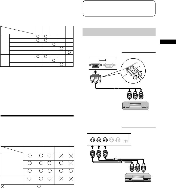
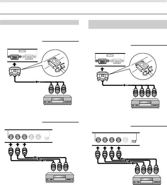
Connection to AV component that has
component video jacks
Make component video connections for AV components such as DVD and LD players or similar components with component video output capability.
When connecting to INPUT1
|
INPUT1 |
ANALOG RGB |
OUTPUT |
(ANALOG RGB) |
On-screen setup is necessary after connection. Please see page 18.
When connecting to INPUT2
(ON SYNC) |
|
INPUT2 |
(H/V SYNC) |
|
G |
B |
R |
HD |
VD |
75Ω Ô2k.Ω2
Connect the Y signal to the G terminal, the CB/PB signal to the B terminal, and the CR/PR signal to the R terminal. On-screen setup is necessary after connection.
Please see page 18.
9
Installation and Connections
PRO-1000HDI / PRO-800HDI
Installation and Connections
Connection of G ON SYNC analog RGB source
Make G ON SYNC connections for a component with output that has the synchronization signal layered on top of the green signal.
When connecting to INPUT1
|
INPUT1 |
ANALOG RGB |
OUTPUT |
(ANALOG RGB) |
On screen setup is necessary after connection. Please see pages 18 and 19.
When connecting to INPUT2
(ON SYNC) |
|
INPUT2 |
(H/V SYNC) |
|
G |
B |
R |
HD |
VD |
75Ω Ô2.2kΩ
On screen setup is necessary after connection. Please see pages 18 and 19.
Note
When making G ON SYNC connections, do not make any connections to the VD or HD terminals. If connections are made, the picture may be not displayed normally.
10
Connection of composite SYNC analog RGB
source
Make composite SYNC connections for a component with output that has the vertical synchronization signal layered on top of the horizontal synchronization signal.
When connecting to INPUT1
|
INPUT1 |
ANALOG RGB |
OUTPUT |
(ANALOG RGB) |
On-screen setup is necessary after connection. Please see pages 18 and 19.
When connecting to INPUT2
(ON SYNC) |
|
INPUT2 |
(H/V SYNC) |
|
G |
B |
R |
HD |
VD |
75Ω Ô2.Ω2 k
When using INPUT2, set the impedance selector switch to match the output impedance of the connected component’s synchronization signal.
When the output impedance of the component’s synchronization signal is below 75 Ω , set this switch to the 75 Ω position.
On-screen setup is necessary after connection. Please see pages 18 and 19.
Note
When making composite SYNC connections, do not connect anything to the VD terminal. If connected to, the picture may not be displayed properly.
PRO-1000HDI / PRO-800HDI
Installation and Connections
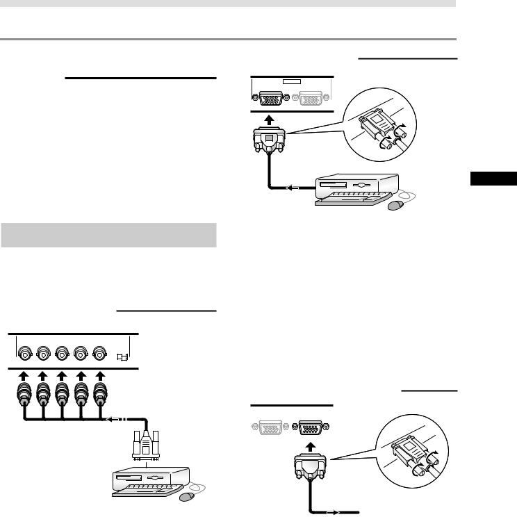
Connection to a personal computer
Connection method differs depending on the computer type. When connecting, please thoroughly read the computer’s instruction manual.
Before making connections, be sure to make sure that the personal computer’s power and this unit’s main power is off.
For the PC input signals and screen sizes that this unit is compatible with, please refer to supplement 1 (pages 39 to 40).
Connection of separate SYNC analog RGB
source
Make separate SYNC connections for a personal computer that has RGB output separated into 5 output signals: green, blue, red, horizontal synchronization signal, and vertical synchronization signal.
When connecting to INPUT2
(ON SYNC) |
|
INPUT2 |
(H/V SYNC) |
|
G |
B |
R |
HD |
VD |
75Ω Ô2.2kΩ
When connecting to INPUT1
|
INPUT1 |
ANALOG RGB |
OUTPUT |
(ANALOG RGB) |
Connect the cable corresponding to the shape of the input terminal on this unit and the personal computer’s output terminal.
Secure by tightening the terminal screws on both units.
After connecting, on-screen setup is necessary. Please see pages 18 and 19.
Note
Depending on the type of computer model being connected, a conversion connector or adapter etc. provided with the computer or sold separately may be necessary.
For details, please read your PC’s instruction manual or consult the maker or nearest dealer of your computer.
When connecting to OUTPUT (INPUT1)
|
|
INPUT1 |
OUTPUT |
|
||
ANALOG RGB |
|
|
||||
(ANALOG RGB) |
|
|||||
|
|
|
|
|
|
|
|
|
|
|
|
|
|
|
|
|
|
|
|
|
|
|
|
|
|
|
|
To an external monitor
When using INPUT2, set the impedance selector switch to match the output impedance of the connected computer’s synchronization signal.
When the output impedance of the computer’s synchronization signal is below 75 Ω , set this switch to the 75 Ω position.
On-screen setup is necessary after connection. Please see pages 18 and 19.
With this unit, it is possible to output the video signal to an external monitor or other component from the OUTPUT (INPUT1) terminal.
Note
A video signal will not be output from the OUTPUT (INPUT1) terminal when the main power of this unit is off or in standby.
Installation and Connections
11
PRO-1000HDI / PRO-800HDI
 Loading...