


TECHNICAL MANUAL (Ver. 1.0) 
PLASMA DISPLAY MONITOR: PDP-614MX/PDP-61MXE1 TABLE TOP STAND: PDK-TS06
SPEAKER SYSTEM: PDP-S29-LR
PLASMA DISPLAY WALL-MOUNT HARDWARE: PDK-WM03
This manual provides precautions and information for installation, preparation, and handling of the plasma display and its dedicated mounting hardware.
Before installation and preparatory work, choose a safe and appropriate site after thorough consideration of construction, materials used, strength, and surroundings. If adequate safeguards are not in place, immediately halt the installation process and discontinue marketing activities.
CAUTION
 Exclamation marks placed within triangles are intended to alert users to the presence of important safety information. Be sure to read instructions indicated by this symbol.
ABOUT MOUNTING/INSTALLATION
÷This product is sold under the assumption that installation will be performed by experienced, qualified experts. Refer all mounting and installation work to qualified personnel, or consult the nearest PIONEER dealer for assistance.
÷We accept no responsibility for accident or loss resulting from failure to select an appropriate installation site, or for those occurring during assembly, installation, mounting, or operation of this product, or resulting from modifications made to this product, or from natural disasters.
PRECAUTIONS:
•We accept no responsibility for losses resulting from the use of parts other than those supplied by us.
•We guarantee the performance of our products only when they are assembled and adjusted as described in this manual.
•The specifications and external designs shown in this manual are subject to change without notice.

Table of Contents
SPECIFICATIONS |
|
||
1.1 |
Specifications ................................................................. |
3 |
|
1.2 |
External Dimensions ...................................................... |
6 |
|
1.3 |
Part Names and Function ............................................... |
8 |
|
1.4 |
Pin layout ...................................................................... |
10 |
|
1.5 |
Remote Control Unit .................................................... |
11 |
|
INSTALLATION SITE REQUIREMENTS |
|
||
2.1 |
Installation Site Requirements ..................................... |
12 |
|
2.2 |
Installation Conditions .................................................. |
14 |
|
|
2.2.1 |
Heat dissipation ................................................ |
14 |
|
2.2.2 |
Calculating heat quantity ................................... |
15 |
|
2.2.3 |
Product mounting holes .................................... |
15 |
|
2.2.4 Anchoring PC and similar apparatuses .............. |
17 |
|
2.3 |
Installation Procedures ................................................. |
18 |
|
|
2.3.1 |
Transportation precautions ............................... |
18 |
|
2.3.2 Transportation of the unpacked unit ................. |
18 |
|
|
2.3.3 How to use the safety metal fittings and |
|
|
|
|
the screws for safety metal fittings .................. |
18 |
|
2.3.4 |
Wiring ................................................................ |
19 |
2.4 |
Special Installation ........................................................ |
21 |
|
|
2.4.1 |
Mounting to fittings .......................................... |
21 |
|
2.4.2 Hanging on the wall .......................................... |
22 |
|
|
2.4.3 Embedding in the wall ...................................... |
23 |
|
|
2.4.4 Ceiling suspension (with wires) ........................ |
24 |
|
|
2.4.5 Hanging on the wall (lengthwise) ...................... |
26 |
|
|
2.4.6 Place product upright and flush into wall |
|
|
|
|
(embedding in the wall) ..................................... |
28 |
|
2.4.7 |
Installed facing upward ..................................... |
29 |
|
2.4.8 |
Horizontal connections ...................................... |
30 |
|
2.4.9 |
Multiple ............................................................. |
31 |
HOW TO USE THE STANDARD MOUNTING COMPONENTS
3.1 Table Top Stand: PDK-TS06 ......................................... |
32 |
|
3.1.1 |
Specifications .................................................... |
32 |
3.1.2 |
External Dimensions ......................................... |
32 |
3.2 Speaker System: PDP-S29-LR ..................................... |
33 |
|
3.2.1 |
Specifications .................................................... |
33 |
3.2.2 |
External Dimensions ......................................... |
33 |
3.3 Wall-Mounted Type Tiltable Fixed Plasma Display |
|
|
Hardware PDK-WM03 ................................................. |
34 |
|
3.3.1 |
Specifications .................................................... |
34 |
3.3.2 |
External Dimensions ......................................... |
35 |
BEFORE BEGINNING ADJUSTMENT/SETTING |
|
|
4.1 Before Beginning Adjustment ..................................... |
36 |
|
4.1.1 |
Screen Size ....................................................... |
36 |
4.1.2 |
Menu Mode ...................................................... |
37 |
4.1.3 |
Last Memory ..................................................... |
39 |
4.1.4 |
Aging ................................................................. |
39 |
4.2 Normal Operation Mode .............................................. |
40 |
|
4.2.1 About normal operation mode .......................... |
40 |
|
4.2.2 |
POWER ............................................................. |
40 |
4.2.3 |
VOLUME ........................................................... |
40 |
4.2.4 |
MUTING ............................................................ |
40 |
4.2.5 |
DISPLAY ........................................................... |
40 |
4.2.6 |
DIGITAL ZOOM ................................................ |
40 |
4.2.7 |
AUTO SET UP ................................................... |
40 |
4.2.8 |
OFF TIMER ....................................................... |
41 |
4.2.9 SCREEN SIZE Operation (manual) .................... |
41 |
|
4.2.10 SCREEN SIZE Operation with Computer Signals ... |
42 |
|
4.3 Menu Mode ................................................................. |
44 |
|
4.3.1 |
Menu Operations .............................................. |
44 |
4.3.2 Setting the language for the menus ................. |
44 |
|
4.3.3 |
Picture Settings Menu ...................................... |
45 |
|
Adjusting the picture ......................................... |
45 |
|
Setting the picture modes according to the |
|
|
brightness of the room ..................................... |
45 |
|
Reducing noise in the picture ........................... |
45 |
|
Setting the color temperature ........................... |
45 |
|
Adjusting the color to the desired level ............ |
46 |
|
Changing the Gamma Curve ............................. |
46 |
|
Making the Low Tone adjustments .................. |
46 |
|
Adjusting the colors .......................................... |
46 |
4.3.4 |
SOUND Settings Menu ..................................... |
47 |
|
Adjusting the treble, bass and left/right |
|
|
balance and audio input select .......................... |
47 |
2 |
Setting the allocation of the audio connectors ... |
47 |
4.3.5 |
SCREEN Settings Menu ................................... |
47 |
|
Adjusting the Position, Size, PHASE, CLOCK ... |
47 |
4.3.6 |
Option1 Settings Menu ..................................... |
48 |
|
Setting the on-screen display ............................ |
48 |
|
Setting the BNC connectors ............................. |
48 |
|
Checking the signal being transmitted to |
|
|
PC1 terminal ..................................................... |
48 |
|
Setting a computer image to the correct |
|
|
RGB select screen ............................................ |
48 |
|
Setting high definition images to the suitable |
|
|
screen size ........................................................ |
49 |
|
Setting the Input Skip ....................................... |
49 |
|
Resetting to the default values ......................... |
49 |
4.3.7 |
Option2 Settings Menu ..................................... |
50 |
|
Setting the power management for computer |
|
|
images .............................................................. |
50 |
|
STANDBY/ON indicator ..................................... |
50 |
|
Setting the picture to suit the movie ................ |
50 |
|
Reducing burn-in of the screen ......................... |
50 |
|
Setting the gray level for the SIDE MASK ........ |
52 |
|
Setting the screen size for S1/S2 video input ... |
53 |
|
Setting the picture size for RGB input signals ........ |
53 |
|
Setting the signal and black level for DVI signal ..... |
53 |
4.3.8 |
Option3 Settings Menu ..................................... |
54 |
|
Using the timer ................................................. |
54 |
|
Setting the power on mode .............................. |
55 |
|
Enabling/disabling the front panel controls ....... |
55 |
|
Enabling/disabling remote control |
|
|
wireless transmission ....................................... |
55 |
|
Loop Out setting ............................................... |
55 |
|
ID number setting ............................................. |
56 |
|
Video Wall setting ............................................. |
56 |
4.3.9 Advanced OSD Settings Menu ......................... |
58 |
|
|
Setting the menu mode .................................... |
58 |
4.3.10 Color System Settings Menu ............................ |
59 |
|
|
Setting the video signal format ......................... |
59 |
4.3.11 Source Information Menu ................................. |
59 |
|
|
Checking the frequencies, polarities of |
|
|
input signals, and resolution ............................. |
59 |
4.3.12 Memory Area Table .......................................... |
60 |
|
4.4 RS-232C Adjustment Mode ......................................... |
61 |
|
4.4.1 |
Connection method .......................................... |
61 |
4.4.2 |
Communication Conditions ............................... |
61 |
4.4.3 |
Communication format ..................................... |
61 |
4.4.4 |
Command Reference ........................................ |
63 |
PRECAUTIONS ..................................................................... |
84 |
|
5.1 Precautions .................................................................. |
84 |
|
THE PLASMA DISPLAY BURN-IN PHENOMENON ............ |
86 |
|
MAINTENANCE .................................................................... |
87 |
|
CAUTION
•To prevent injury and material damage, thoroughly read this manual and all labels found on the equipment before attempting to mount, install, move, or adjust the product.
•Do not install the unit outside or in the open air. Doing so will lead to water seepage into the system, resulting in fire or electric shock.
•Be especially careful when working around parts of the system that have sharp edges.
•When performing installation work from a height, take suitable precautions to guard against falling. Set up a barrier around the work site to prevent accidentally dropped objects from injuring persons standing or walking below.
•Keep all foreign objects out of the unit. Do not tamper with the unit, or fire or electric shock may result.
•Observe the following operating environmental limitations: Temperature: 0 to 40°C
Humidity: 20 to 80%
•Install the unit only in properly ventilated areas.

Specifications
1.1 Specifications
Product name |
...... 61-inch V AC type plasma display panel |
|
Screen dimensions ...................... |
1,351 (H) x 760 (V) mm |
|
|
|
53.2 (H) x 29.9 (V) inches |
|
(Diagonal dimension 1,550mm (61 inch)) |
|
Aspect ratio ................................................................ |
|
16:9 |
Pixels ..................................................... |
|
1,365 (H) x 768 (V) |
|
(1 pixel consists of RGB 3 color dot trio.) |
|
Pixel pitch .............................................. |
|
0.99 (H) x 0.99 (V) |
Video input signals |
|
|
VIDEO1 |
|
|
BNC pin |
|
1Vp-p/75Ω/negative sync. |
• Composite video signal ........ |
||
VIDEO2 |
|
|
RCA pin |
|
1Vp-p/75Ω/negative sync. |
• Composite video signal ........ |
||
VIDEO3
S pin (Mini DIN4 pin connector)
•Y/C separate video signal
Y ........ 1Vp-p/75Ω/negative sync. C ........ 0.286Vp-p/75Ω / (NTSC)
0.3Vp-p/75Ω (PAL)
COMPONENT1
RCA pin (X3)
• Component video signal
Y .......................... |
1Vp-p/75Ω/negative sync. |
Pb/Cb, Pr/Cr ........ |
0.7Vp-p (color 100%)/75Ω |
PC2/COMPONENT2 *1
BNC pin (X5)
•RGB signal (G ON SYNC compatible) RGB: 0.7Vp-p/75Ω/negative sync H/CS: 5.0Vp-p/2.2kΩ (Min)
V: 5.0Vp-p/33kΩ (Min)
G on Sync: 1Vp-p/75Ω/negative sync
•Component video signal
Y .......................... |
1Vp-p/75Ω/negative sync |
Pb/Cb, Pr/Cr ........ |
0.7Vp-p (color 100%)/75Ω |
PC1 (Analog RGB)
Mini D-sub15 pin connector (female)
•RGB signal (G ON SYNC compatible) RGB: 0.7Vp-p/75Ω/no sync
H/CS: 5.0Vp-p/2.2kΩ (Min)
V: 5.0Vp-p/33kΩ (Min)
Gon Sync: 1Vp-p/75Ω/negative sync
* Microsoft Plug and Play (VESA DDC 1/2B) compatible
PC3 (Digital RGB)
DVI-D 24 pin
• Digital RGB signal
(DVI 1.0 standard, HDCP (EIA/CEA-861) compatible) * Microsoft Plug and Play (VESA DDC 2B) compatible
Video output pins *2
VIDEO1 ........ Outputs the input signal to the VIDEO2 pin PC1 ...... Outputs the input signal to the PC2/COMPONENT2
Audio input pins
AUDIO1
RCA pin (pin jack) (x2)
L/R ............. 500mVrms/22kΩ or more
AUDIO2
RCA pin (pin jack) (X2)
L/R ............. 500mVrms/22kΩ or more
AUDIO3
RCA pin (pin jack) (X2)
L/R ............. 500mVrms/22kΩ or more
Audio output pins *3
Speaker pins
L/R: 9W+9W at 6Ω
External control pins
RS-232C pins
D-sub 9-pin (male) x1
Wired remote control input pin
Stereo mini-jack x1
Wired remote control output pin
Stereo mini-jack x1 (loop through output)*4
Power requirements |
|
|
PDP-614MX ............................ |
AC100V to 120V, 50/60Hz |
|
PDP-61MXE1 .......................... |
AC100V to 240V, 50/60Hz |
|
In-rush .......................................................... |
|
less than 50A |
Power factor .............................................. |
|
more than 0.92 |
Consumption ....................... |
540W(Note 1)(0.9W in standby) |
|
External dimensions .... 1,470 (W) x 880 (H) x 119 (D) mm |
||
57.9 (W) x 34.7 (H) x 4.7 (D) inches |
||
Weight ................................................... |
|
61.0 kg / 134.5 lbs |
Operating temperature ........................ |
|
0°C to 40°C(Note 2) |
Operating humidity ......................................... |
|
20 to 80% |
Operating atmospheric pressure |
............ 720 to 1114hPa |
|
Storage limitations |
|
|
Temperature .............................................. |
|
-10°C to 50°C |
Humidity ......................................................... |
|
10 to 90% |
Atmospheric pressure ............................ |
|
700 to 1114hPa |
Stacking (when packaged) ................... |
|
fewer than 2 tiers |
Standard accessories |
|
|
Power cord (3m) ............................................................ |
|
1 |
Remote control unit ....................................................... |
|
1 |
AAA battery ................................................................... |
|
2 |
Wiping cloth (screen) ..................................................... |
|
1 |
Ferrite core (large) ......................................................... |
|
2 |
Ferrite core (small) ......................................................... |
|
2 |
Cable band ..................................................................... |
|
2 |
Cable clamp ................................................................... |
|
5 |
Safety hardware ...................................................... |
|
1 set |
Operating instructions ................................................... |
|
1 |
Plasma precautions ....................................................... |
|
1 |
Burn-in precautions ....................................................... |
|
1 |
Caution sheet ................................................................ |
|
1 |
Warranty ........................................................................ |
|
1 |
Specifications and external design are subject to change without notice.
*1: 5BNC input permits switching between RGB and component input using the on-screen menu setting.
*2: The VIDEO1 pin and PC1 pin permit switching between video output/input pins using the on-screen menu setting. Loop through output does not assure video quality. When video quality cannot be obtained, the use of a video distributor or similar external apparatus is recommended.
*3: The audio input pins can each be allotted to all video input pins using the on-screen menu settings.
*4: It can be operated with the wired cables connecting and linking the remote control output pins, but only up to nine.
(Note 1) Allow for 540W ≠ 540VA of consumption per unit. (Note 2) The correct operating environment temperature
may vary, depending on the installation site. (Refer to Installation Site Requirements)
3

Specifications
INPUT Response Signals
7 PC signals supported
• When the screen size is 4:3, each signal is converted to a 1024 dots × 768 lines signal. (Except for *2, 3, 4)
•When the screen size is Dot by Dot, the picture is displayed in the original resolution.
•When the screen size is FULL, each signal is converted to a 1365 dots × 768 lines signal. (Except for *3)
Computer input signals supported by this system
Model |
|
Dots 2 lines |
Vertical |
Horizontal |
Sync Polarity |
Presence |
Screen size |
|
RGB |
DVI |
Memory |
|||
|
frequency |
frequency |
Horizontal |
Vertical |
Horizontal |
Vertical |
4:3 |
D BY D |
FULL |
select*5 |
||||
|
Signal Type |
|
(Hz) |
(kHz) |
|
|
|
|
|
|
(16:9) |
|
|
|
|
|
640× 400 |
70.1 |
31.5 |
NEG |
NEG |
YES |
YES |
YES*2 |
YES |
YES |
– – |
NO |
4 |
|
|
640× 480 |
59.9 |
31.5 |
NEG |
NEG |
YES |
YES |
YES |
YES |
YES |
STILL |
YES |
5 |
|
|
|
72.8 |
37.9 |
NEG |
NEG |
YES |
YES |
YES |
YES |
YES |
– – |
YES |
7 |
|
|
|
75.0 |
37.5 |
NEG |
NEG |
YES |
YES |
YES |
YES |
YES |
STILL |
YES |
8 |
|
|
|
85.0 |
43.3 |
NEG |
NEG |
YES |
YES |
YES |
YES |
YES |
– – |
YES |
9 |
|
|
|
100.4 |
51.1 |
NEG |
NEG |
YES |
YES |
YES |
YES |
YES |
– – |
YES |
41 |
|
|
|
120.4 |
61.3 |
NEG |
NEG |
YES |
YES |
YES |
YES |
YES |
– – |
YES |
42 |
|
|
848× 480 |
60.0 |
31.0 |
POS |
POS |
YES |
YES |
– – |
YES |
YES |
WIDE2 |
YES |
19 |
|
|
852× 480*1 |
60.0 |
31.7 |
NEG |
NEG |
YES |
YES |
– – |
YES |
YES |
WIDE1 |
YES |
17 |
|
|
800× 600 |
56.3 |
35.2 |
POS |
POS |
YES |
YES |
YES |
YES |
YES |
STILL |
YES |
11 |
|
|
|
60.3 |
37.9 |
POS |
POS |
YES |
YES |
YES |
YES |
YES |
STILL |
YES |
12 |
|
|
|
72.2 |
48.1 |
POS |
POS |
YES |
YES |
YES |
YES |
YES |
– – |
YES |
13 |
|
|
|
75.0 |
46.9 |
POS |
POS |
YES |
YES |
YES |
YES |
YES |
– – |
YES |
14 |
|
|
|
85.1 |
53.7 |
POS |
POS |
YES |
YES |
YES |
YES |
YES |
– – |
YES |
15 |
IBM PC/AT*8 |
|
99.8 |
63.0 |
POS |
POS |
YES |
YES |
YES |
YES |
YES |
– – |
YES |
43 |
|
compatible |
|
120.0 |
75.7 |
POS |
POS |
YES |
YES |
YES |
YES |
YES |
– – |
YES |
44 |
|
computers |
1024× 768 |
60.0 |
48.4 |
NEG |
NEG |
YES |
YES |
YES*3 |
– – |
YES |
STILL |
YES |
24 |
|
|
|
|
70.1 |
56.5 |
NEG |
NEG |
YES |
YES |
YES*3 |
– – |
YES |
– – |
YES |
25 |
|
|
|
75.0 |
60.0 |
POS |
POS |
YES |
YES |
YES*3 |
– – |
YES |
STILL |
YES |
26 |
|
|
|
85.0 |
68.7 |
POS |
POS |
YES |
YES |
YES*3 |
– – |
YES |
– – |
YES |
27 |
|
|
|
100.6 |
80.5 |
NEG |
NEG |
YES |
YES |
YES*3 |
– – |
YES |
– – |
YES |
45 |
|
|
1152× 864 |
75.0 |
67.5 |
POS |
POS |
YES |
YES |
YES |
– – |
YES |
STILL |
YES |
51 |
|
|
1280× 768 |
56.2 |
45.1 |
NEG |
NEG |
YES |
YES |
– – |
YES |
YES |
WIDE1 |
NO |
52 |
|
|
|
59.8 |
48.0 |
NEG |
POS |
YES |
YES |
– – |
YES |
YES |
WIDE4 |
YES |
23 |
|
|
|
69.8*9 |
56.0*9 |
NEG |
POS |
YES |
YES |
– – |
YES |
YES |
WIDE1 |
YES |
66 |
|
|
1280× 800*9 |
60.0 |
49.7 |
NEG |
NEG |
YES |
YES |
– – |
– – |
YES |
WIDE1 |
YES |
21 |
|
|
1280× 854*9 |
60.0 |
53.1 |
NEG |
NEG |
YES |
YES |
– – |
– – |
YES |
WIDE2 |
YES |
37 |
|
|
1360× 765 |
60.0 |
47.7 |
POS |
POS |
YES |
YES |
– – |
– – |
YES*3 |
WIDE1 |
NO |
22 |
|
|
1360× 768 |
60.0 |
47.7 |
POS |
POS |
YES |
YES |
– – |
– – |
YES*3 |
WIDE1 |
YES |
22 |
|
|
1376× 768 |
59.9 |
48.3 |
NEG |
POS |
YES |
YES |
– – |
– – |
YES |
WIDE2 |
YES |
53 |
|
|
1280× 1024 |
60.0 |
64.0 |
POS |
POS |
YES |
YES |
YES*4 |
– – |
YES |
STILL |
YES |
29 |
|
|
|
75.0 |
80.0 |
POS |
POS |
YES |
YES |
YES*4 |
– – |
YES |
– – |
YES |
30 |
|
|
|
85.0 |
91.1 |
POS |
POS |
YES |
YES |
YES*4 |
– – |
YES |
– – |
YES |
40 |
|
|
|
100.1 |
108.5 |
POS |
POS |
YES |
YES |
YES*4 |
– – |
YES |
– – |
NO |
47 |
|
|
1680× 1050*9 |
60.0 |
65.3 |
NEG |
NEG |
YES |
YES |
– – |
– – |
YES |
WIDE4 |
YES |
38 |
|
|
1600× 1200 |
60.0 |
75.0 |
POS |
POS |
YES |
YES |
YES |
– – |
YES |
– – |
YES |
54 |
|
|
|
65.0 |
81.3 |
POS |
POS |
YES |
YES |
YES |
– – |
YES |
– – |
NO |
55 |
|
|
|
70.0 |
87.5 |
POS |
POS |
YES |
YES |
YES |
– – |
YES |
– – |
NO |
56 |
|
|
|
75.0 |
93.8 |
POS |
POS |
YES |
YES |
YES |
– – |
YES |
– – |
NO |
57 |
|
|
|
85.0 |
106.3 |
POS |
POS |
YES |
YES |
YES |
– – |
YES |
– – |
NO |
58 |
|
|
1920× 1200*9 |
60.0 |
74.6 |
NEG |
NEG |
YES |
YES |
– – |
– – |
YES |
WIDE2 |
NO |
81 |
|
|
1920×1200RB*9 |
60.0 |
74.0 |
NEG |
NEG |
YES |
YES |
– – |
– – |
YES |
WIDE3 |
YES |
88 |
Apple Macintosh*6 *8 |
640× 480 |
66.7 |
35.0 |
Sync on G |
Sync on G |
– – |
– – |
YES |
YES |
YES |
– – |
NO |
6 |
|
|
|
832× 624 |
74.6 |
49.7 |
Sync on G |
Sync on G |
– – |
– – |
YES |
YES |
YES |
– – |
NO |
16 |
|
|
1024× 768 |
74.9 |
60.2 |
Sync on G |
Sync on G |
– – |
– – |
YES*3 |
– – |
YES |
WIDE1 |
NO |
28 |
|
|
1152× 870 |
75.1 |
68.7 |
Sync on G |
Sync on G |
– – |
– – |
YES |
– – |
YES |
WIDE1 |
NO |
39 |
|
|
1440× 900*9 |
60.0 |
56.0 |
NEG |
NEG |
YES |
YES |
– – |
– – |
YES |
– – |
YES |
89 |
Work |
EWS4800*8 |
1280× 1024 |
60.0 |
64.6 |
NEG |
NEG |
YES |
YES |
YES*4 |
– – |
YES |
– – |
YES |
29 |
Station |
|
|
71.2 |
75.1 |
NEG |
NEG |
YES |
YES |
YES*4 |
– – |
YES |
– – |
YES |
48 |
|
HP*8 |
1280× 1024 |
72.0 |
78.1 |
– – |
– – |
– – |
– – |
YES*4 |
– – |
YES |
– – |
YES |
59 |
|
SUN*8 |
1152× 900 |
66.0 |
61.8 |
C Sync |
C Sync |
– – |
– – |
YES |
– – |
YES |
– – |
YES |
60 |
|
|
|
76.0 |
71.7 |
C Sync |
C Sync |
– – |
– – |
YES |
– – |
YES |
– – |
YES |
61 |
|
|
1280× 1024 |
76.1 |
81.1 |
C Sync |
C Sync |
– – |
– – |
YES*4 |
– – |
YES |
– – |
YES |
30 |
|
SGI |
1024× 768 |
60.0 |
49.7 |
– – |
– – |
– – |
– – |
YES*3 |
– – |
YES |
– – |
YES |
62 |
|
|
1280 ×1024 |
60.0 |
63.9 |
– – |
– – |
– – |
– – |
YES*4 |
– – |
YES |
– – |
YES |
29 |
IDC-3000G |
PAL625P |
768× 576 |
50.0 |
31.4 |
NEG |
NEG |
YES |
YES |
YES*7 |
– – |
YES*7 |
– – |
NO |
31 |
|
NTSC525P |
640× 480 |
59.9 |
31.5 |
NEG |
NEG |
YES |
YES |
YES*7 |
– – |
YES*7 |
MOTION |
NO |
32 |
4
Specifications
*1 Only when using a graphic accelerator board that is capable of displaying 852 × 480. *2 This signal is converted to a 1024 dots × 640 lines signal.
*3 The picture is displayed in the original resolution.
*4 The aspect ratio is 5:4. This signal is converted to a 960 dots × 768 lines signal.
*5 Normally the RGB select mode suite for the input signals is set automatically. If the picture is not displayed properly, set the RGB mode prepared for the input signals listed in the table above.
*6 To connect the monitor to Macintosh computer, use the monitor adapter (D-Sub 15-pin) to your computer's video port. *7 Other screen sizes (ZOOM and WIDE) are available as well.
*8 When viewing a moving picture at a vertical frequency greater than 65Hz, the picture may sometimes be unstable (jumpy). If this occurs, please set the refresh rate of the external equipment to 60Hz.
To view 480I@60Hz (480 interlaced lines, 60Hz refresh rate) or 576I@50Hz (567 interlaced lines, 50Hz refresh rate) when sync polarity is “Sync on Green”, set “RGB SELECT” to “MOTION”.
*9 CVT standard compliant.
NOTE:
•While the input signals comply with the resolution listed in the table above, you may have to adjust the position and size of the picture or the fine picture because of errors in synchronization of your computer.
•When a 1280 dots × 1024 lines signal or 1600 dots × 1200 lines signal is input to the monitor, the picture will be compressed.
•This monitor has a resolution of 1365 dots × 768 lines. It is recommended that the input signal should be XGA, wide XGA, or equivalent.
•With digital input some signals are not accepted.
•The sync may be disturbed when a nonstandard signal other than the aforementioned is input.
•If you are connecting a composite sync signal, use the HD terminal.
•“IBM PC/AT” and “XGA” are registered trademarks of International Business Machines, Inc. of the United States.
•“Apple Macintosh” is a registered trademark of Apple Computer, Inc. of the United States.
7 Video signals supported
Vertical |
Horizontal |
|
|
|
Frequency |
Frequency |
Signal Format |
Remarks |
|
fV (Hz) |
fH (kHz) |
|
|
|
|
15.625 |
Component |
625I (576I)/SDTV |
|
|
|
RGB |
|
|
|
|
|
|
|
50 |
28.13 |
Component |
1125I (1080I)/ HDTV |
|
|
RGB |
|
||
|
|
|
||
|
31.25 |
Component |
625P (576P)/SDTV |
|
|
|
RGB |
|
|
|
|
|
|
|
|
15.734 |
Component |
525I (480I)/SDTV |
|
|
|
RGB |
|
|
|
|
|
|
|
|
31.5 |
Component |
525P (480P)/SDTV |
|
60 |
|
RGB |
|
|
33.75 |
Component |
1125I (1080I)/ HDTV |
||
|
||||
|
|
RGB |
1125I (1035I)/ HDTV |
|
|
45.0 |
Component |
750P (720P)/HDTV |
|
|
|
RGB |
|
|
|
|
|
|
7 DVI HDCP signals supported
Vertical |
Horizontal |
|
|
Frequency |
Frequency |
Remarks |
|
fV (Hz) |
fH (kHz) |
|
|
|
31.3 |
720 x 576P |
|
|
|
|
|
50 |
37.5 |
1280 x 720P* |
|
|
|
||
28.1 |
1920 x 1080I |
||
|
|||
|
|
|
|
|
15.6 |
720 (1440) x 576I |
|
|
|
|
|
|
31.5 |
640 x 480P (EIA/CEA-861) |
|
|
|
720 x 480P |
|
60 |
|
|
|
45.0 |
1280 x 720P |
||
|
|
|
|
|
33.8 |
1920 x 1080I |
|
|
|
|
|
|
15.8 |
720 (1440) x 480I |
|
|
|
|
* No support of EDID
5

External Dimensions
1.2 External Dimensions
Weight: 61.0 kg
Material: Front: Resin; Rear cover: Metal plate, Front protector panel: Glass Treatment: Front: Paint; Rear cover: Paint (All paints are Pioneer original colors)
(Unit: mm)
49
1550
(SCREEN AREA) |
782 |
880 |
760 |
|
|
1351 (SCREEN AREA)
49
FILTER SURFACE
118.9
515 (for SPEAKER) |
880 |
515 (for SPEAKER M4x4) |
264.8 200.8 |
162.5 |
|
162.5 |
175.2 |
54.9 |
|
5.2 |
1 |
109 |
|
81.1 |
|||
|
|
|
|
|
45 |
74 |
|
|
|
|
119 |
|
|
|
POWER BUTTON
592.5
1372
1470
|
|
|
214 |
|
|
850 (for Option M8x6) |
|
OptionM8x6) |
250 |
|
102 (for PC) |
445 (for PC M4x4) |
124 |
||
|
|
|
|
500 (for |
|
|
|
|
|
35 |
|
850
1470
SPEAKER TERMINAL |
AC INLET |
IR |
70 |
|
425 |
|
425 |
70 |
|
|
|||
|
|
|
|
||||||||
|
|
|
|
|
|
|
|
|
|
||
200.5 |
|
534.5 |
|
505 |
|
|
|
|
|
||
49
49 LED&IR
|
27.9 |
|
8˚ |
|
4.5 |
|
420 |
SPEAKERM4x4) |
80.9 |
880 |
|
515 (for |
420 |
162.5 |
|
20 |
81.1 |
1 |
103 |
|
119 |
|
26.5 |
|
119 |
||
|
|||||
|
|
|
|||
|
|
|
|
||
|
|
|
|
|
|
LOCAL CONTROL
130
20
20
20 20 20
6
External Dimensions
<Light Sensor for the Remote> |
<Connection Panel> |
10.5
135
160
<Main Unit Operation Panel>
POWER
BUTTON
26.5 |
119 |
IR
LOCAL CONTROL
200.5 |
130 |
20
20
20
20
20
32 28 32 18 18 18 18 20 14 15 15 16 17 18.5 33
16 29 71.5
7
Part Names and Function
1.3 Part Names and Function
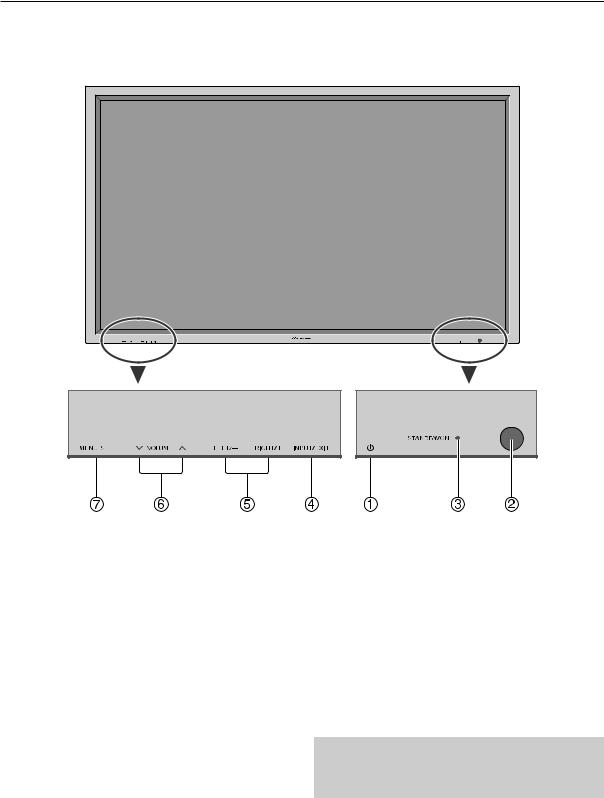
Front View
1Power (  )
)
Turns the monitor’s power on and off.
2Remote sensor window
Receives the signals from the remote control.
3STANDBY/ON indicator
When the power is on .......................... Lights green. When the power is in the standby mode .... Lights red.
4INPUT/EXIT
Switches the input.
The available inputs depend on the setting of “BNC INPUT”, “RGB SELECT” and “DVI SET UP”. Functions as the EXIT buttons in the On-Screen Display (OSD) mode.
5LEFT/– and RIGHT/+
Functions as the CURSOR (2 / 3) buttons in the OnScreen Display (OSD) mode.
6VOLUME  and
and 
Adjusts the volume. Functions as the CURSOR (5/∞) buttons in the On-Screen Display (OSD) mode.
7MENU/SET
Sets the On-Screen Display (OSD) mode and displays the main menu.
WARNING
The Power on/off switch does not disconnect the plasma display completely from the supply mains.
8
Part Names and Function
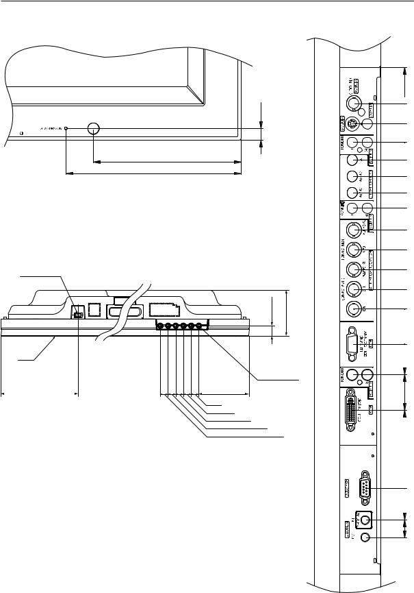
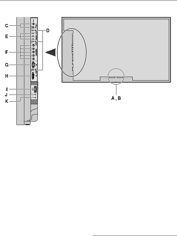
Rear View/ Terminal Board
AAC IN
Connect the included power cord here.
BEXT SPEAKER L and R
Connect speakers (optional) here. Maintain the correct
polarity. Connect the  (positive) speaker wire to the
  EXT SPEAKER terminal and the
 (negative) speaker wire to the
 EXT SPEAKER terminal on both LEFT and RIGHT channels.
Please refer to your speaker’s owner’s manual.
CVIDEO1, 2, 3 (BNC, RCA, S-Video)
Connect VCR’s, DVD’s or Video Cameras, etc. here. VIDEO1 can be used for Input or Output.
DAUDIO1, AUDIO2, AUDIO3
These are audio input terminals.
The input is selectable. Set which video image to allot them from the SOUND menu screen.
ECOMPONENT1
Connect DVD’s, High Definition or Laser Discs, etc. here.
F PC2/COMPONENT2
PC2: |
You can connect an analog RGB signal |
|
and the syncronization signal. |
COMPONENT2: You can connect DVDs, High Definition sources, Laser Discs, etc. here.
This input can be set for use with an RGB or component source.
GPC1 (mini D-Sub 15pin)
Connect an analog RGB signal from a computer, etc. here. This input can be used for Input or Output.
HPC3 (DVI 24pin)
Connect a digital signal (TMDS) from a source with a DVI output.
IRS-232C
Never connect any component to this connector without first consulting your Pioneer installation technician.
This connector is used for plasma display setup adjustments.
JREMOTE IN
Connect the remote cable* to the remote control’s remote jack to obtain wired remote control.
KREMOTE OUT
Connect the remote cable* to the REMOTE IN jack of the other display monitor to obtain wired remote control.
* The 1/8 Stereo Mini cable must be purchased separately.
9
Pin layout
1.4 Pin layout
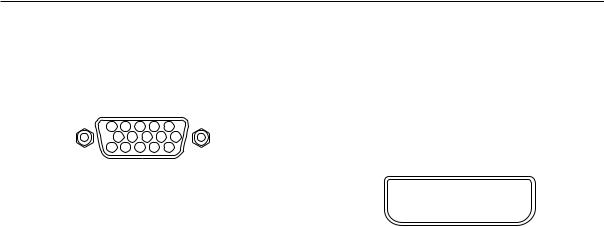
mini D-Sub 15-pin connector (Analog)
PC 1
5 4 3 2 1
10 |
9 |
8 |
7 |
6 |
|
15 |
14 |
|
13 |
12 |
11 |
DVI-D 24-pin connector (Digital)
The unit is equipped with a type of connector commonly used for digital.
(This cannot be used for an analog input.) (TMDS can be used for one link only.)
PC 3
Pin No. |
Signal (Analog) |
|
|
|
|
1 |
|
2 |
|
3 |
|
4 |
|
5 |
|
6 |
|
7 |
|
8 |
|
|
|
|
|
|
|
|
|
|
|
|
|
|
|
|
|
|
|
|
|
|
|
|
|
|
|
||
1 |
Red |
|
|
|
|
9 |
|
10 |
|
11 |
|
12 |
|
13 |
|
14 |
|
15 |
|
16 |
|
|
|
|
2 |
Green or sync-on-green |
|
|
|
|
17 |
|
18 |
|
19 |
|
20 |
|
21 |
|
22 |
|
23 |
|
24 |
|
|
|
|
|
|
|
|
|
|
|
|
|
|
|
|
|
|
|
|
|
|
|
|
|
|
|
||
3 |
Blue |
|
|
|
|
|
|
|
|
|
|
|
|
|
|
|
|
|
|
|
|
|
|
|
|
|
|
|
|
|
|
|
|
|
|
|
|
|
|
|
|
|
|
|
|
|
|
|
|
4 |
No connection |
|
|
|
|
|
|
|
|
|
|
|
|
|
|
|
|
|
|
|
|
|
|
|
5 |
Ground |
|
|
Pin No. |
|
|
|
|
|
|
|
Signal (Digital) |
||||||||||||
6 |
Red ground |
|
|
1 |
T.M.D.S Data 2 - |
|
|
|
|
|
|
|
|
|
|
|
|
|||||||
7 |
Green ground |
|
|
2 |
T.M.D.S Data 2 + |
|
|
|
|
|
|
|
|
|
|
|
|
|||||||
8 |
Blue ground |
|
|
3 |
T.M.D.S Data 2 Shield |
|
|
|
|
|
|
|
|
|
||||||||||
9 |
No connection |
|
|
|
|
|
|
|
|
|
|
|
|
|
|
|
|
|
|
|
|
|
|
|
|
4 |
No connection |
|
|
|
|
|
|
|
|
|
|
|
|
|
|||||||||
10 |
Sync signal ground |
|
|
5 |
No connection |
|
|
|
|
|
|
|
|
|
|
|
|
|
||||||
11 |
No connection |
|
|
6 |
DDC Clock |
|
|
|
|
|
|
|
|
|
|
|
|
|
|
|
|
|||
12 |
Bi-directional DATA (SDA) |
|
7 |
DDC Data |
|
|
|
|
|
|
|
|
|
|
|
|
|
|
|
|
|
|||
13 |
Horizontal sync or Composite sync |
|
|
8 |
No connection |
|
|
|
|
|
|
|
|
|
|
|
|
|
||||||
14 |
Vertical sync |
|
|
9 |
T.M.D.S Data 1 - |
|
|
|
|
|
|
|
|
|
|
|
|
|||||||
15 |
Data clock |
|
|
10 |
T.M.D.S Data 1 + |
|
|
|
|
|
|
|
|
|
|
|
|
|||||||
|
|
|
|
11 |
T.M.D.S Data 1 Shield |
|
|
|
|
|
|
|
|
|
||||||||||
|
|
|
|
12 |
No connection |
|
|
|
|
|
|
|
|
|
|
|
|
|
||||||
|
|
|
|
13 |
No connection |
|
|
|
|
|
|
|
|
|
|
|
|
|
||||||
|
|
|
|
|
|
|
|
|
|
|
|
|
|
|
|
|
|
|
|
|
|
|
|
|
|
|
|
14 |
+5V Power |
|
|
|
|
|
|
|
|
|
|
|
|
|
|
|
|
||||
|
|
|
|
15 |
Ground |
|
|
|
|
|
|
|
|
|
|
|
|
|
|
|
|
|
||
|
|
|
|
16 |
Hot Plug Detect |
|
|
|
|
|
|
|
|
|
|
|
|
|
||||||
|
|
|
|
17 |
T.M.D.S Data 0 - |
|
|
|
|
|
|
|
|
|
|
|
|
|||||||
|
|
|
|
|
|
|
|
|
|
|
|
|
|
|
|
|
|
|
|
|
|
|
||
|
|
|
18 |
T.M.D.S Data 0 + |
|
|
|
|
|
|
|
|
|
|
|
|
||||||||
|
|
|
|
19 |
T.M.D.S Data 0 Shield |
|
|
|
|
|
|
|
|
|
||||||||||
|
|
|
|
|
|
|
|
|
|
|
|
|
|
|
|
|
|
|
|
|
|
|
|
|
|
|
|
20 |
No connection |
|
|
|
|
|
|
|
|
|
|
|
|
|
|||||||
|
|
|
21 |
No connection |
|
|
|
|
|
|
|
|
|
|
|
|
|
|||||||
|
|
|
|
|
|
|
|
|
|
|
|
|
|
|
|
|
|
|
|
|
|
|||
|
|
|
22 |
T.M.D.S Clock Shield |
|
|
|
|
|
|
|
|
|
|||||||||||
|
|
|
|
23 |
T.M.D.S Clock + |
|
|
|
|
|
|
|
|
|
|
|
|
|
||||||
|
|
|
|
24 |
T.M.D.S Clock - |
|
|
|
|
|
|
|
|
|
|
|
|
|
||||||
10
Remote Control Unit
1.5 Remote Control Unit
~ POWER ON/STANDBY |
Switches the power on/standby.
(This does not operate when STANDBY/ON indicator of the main unit is off.)
Ÿ RGB/PC
Press this button to select RGB/PC as the source. RGB/PC can also be selected using the INPUT/EXIT button on the monitor.
!COMPONENT
Press this button to select COMPONENT as the source. COMPONENT can also be selected using the INPUT/EXIT button on the monitor.
⁄VIDEO
Press this button to select VIDEO as the source.
→VIDEO1 → VIDEO2 → VIDEO3
VIDEO can also be selected using the INPUT/EXIT button on the monitor.
@MENU/SET
Press this button to access the OSD controls.
Press this button during the display of the main menu to go to the sub menu.
¤CURSOR (5 / ∞ / 2 / 3)
Use these buttons to select items or settings and to adjust settings.
#EXIT
Press this button to exit the OSD controls in the main menu. Press this button during the display of the sub menu to return to the previous menu.
‹POINT ZOOM
Press this button to display the pointer.
$ZOOM (+ /–)
Enlarges or reduces the image.
›VOLUME (+ /–)
Adjusts the sound volume.
%MUTING
Mutes the sound.
fiSCREEN SIZE
Automatically detects the signal and sets the aspect ratio. SCREEN SIZE button is not active for all signals.
^DISPLAY
Displays the source settings on the screen.
flOFF TIMER
Activates the off timer for the unit.
&AUTO SET UP
Press this button to adjust PHASE, CLOCK, Position, and Contrast automatically, or to switch the screen size to ZOOM mode automatically with the superimposed caption displayed fully only when the picture contains dark areas above and below the picture.
‡ID NO. SET
Set the ID number in the remote control. The remote control can then be used only for a display with the same ID number. When several displays are used together they can be controlled individually.
*CLEAR
Clears the number set by the ID NO. SET button.
°Remote control signal transmitter
Transmits the remote control signals.
(Remote Jack
Insert the plug of the remote cable (The 1/8 Stereo Mini cable) here when using the supplied remote control in the wired condition.
11

Installation Site Requirements
2.1 Installation Site Requirements
If the site requires modifications or special preparations for installation of the plasma display or its mounting hardware, obtain permission in advance from the building owner or building authorities. To ensure installations safety, it is also important to determine the strength of the installation site with the help of the original building contractor.
Safety Precautions
1) Structure of the installation site
Make sure you thoroughly understand the structure of the installation site before determining the most suitable installation method. Buildings vary in structure and materials, and the appropriate mounting hardware with differ accordingly. When drilling into walls, always remain aware of the internal electric wiring and pipes.
2) Weight capacity of the installation site
Select a location with a weight capacity sufficient to support the total weight of the display and mounting hardware.
3) Flat, level surfaces
Select a flat, level surface for installation, such that mounting software will be parallel to the surface to which it is affixed. Install the unit so that the load is evenly distributed along the ceiling or floor, as well as on mounting hardware such as hang bolts.
4) Sufficient work space
Select a location with sufficient space for installation work.
5) Nearby equipment
If air conditioning ducts or lamps, etc. are located near the installation site, the attendant dust, extreme temperatures, humidity, and condensation may become sources of trouble. Please take sufficient steps to avoid this.
6) Safe locations
Do not install the unit where it may be easily touched or leaned against. Avoid locations subject to high vibration or severe impacts.
7) Lighting conditions
•Consider existing lighting and sunlight angles when creating the installation layout. Extremely bright lighting can reduce the visibility and quality of the display image.
•In extremely bright surroundings, adjusting screen intensity may not result in perceptibly brighter images. Keep in mind that extreme intensity settings can reduce system service life.
8) Other installation conditions
The unit is designed for indoor use, and is not suited for open-air use. Installation in locations that are even partially exposed to the elements may lead to malfunctions or breakdown caused by any of the following. And if there is danger of it being exposed to similar effects even when installed indoors, it is necessary to block the outside air by cooling the casing etc.
•Water and dust
•Changes in temperature and humidity
•Salt-bearing wind
Direct sunlight upon the display degrades image quality. In installing the display, avoid sites exposed to direct sunlight.
9) Temperature and humidity conditions
•The installation site should meet the following conditions:
•Operating temperatures: 0 to 40 °C (largely depending on installation conditions)
•Operating humidity: 20 to 80 %
•Storage temperature: –10 to 50 °C
•Storage humidity: 10 to 90 %
•Operating atmospheric pressure: 720 to 1114 hPa
•Storage atmospheric pressure: 700 to 1114 hPa
•We recommend against installing electronic products such as this unit in locations subject to high humidity. If the unit is to be installed in a location subject to relatively high humidity, observe the following:
•Failure to install the unit in unacceptable ways may result in non-warranty damages.
•Make sure the unit is grounded.
•Do not allow water or other liquids to enter the unit.
12

Installation Site Requirements
10) Prevent condensation
One of the chief sources of problems during the winter is ‘condensation’. Rapid temperature fluctuations can deposit water vapor inside the unit or on the screen, degrading performance. If condensation occurs, turn the unit off and leave it off for an hour or so. It is also good practice to increase the room temperature gradually.
Beware of condensation. Consult Pioneer authorized dealers for assistance.
11) Power requirements
•This unit functions properly when powered at ±10 % of its rated voltage. Characteristics of power lines may effect the voltage output. If any of the following occurs, contact an electrician to inspect the power.
•Significant voltage drop between the circuit panel and the plasma display
•Significant changes in voltage when switching the unit power on or off
•Please consider the following to allow a margin for power consumption per unit. 540 W ≠ 540 VA
(NOTE)
•The in-rush current upon powering will be approximately 50 A.
•A grounded three-core power cable is used by the plasma display in order to maintain its functions.
Connect the power cord by inserting it in a grounded electrical outlet, making sure that the cord is properly grounded. When using a power source use conversion plug, insert it in a grounded electrical outlet and securely attach the ground wire.
•A leakage current within a value stipulated by standards in each country flows from an internal noise filter through devices installed inside switching power sources such as television sets or air-conditioners. Because these currents are added together when multiple units are used, be careful to avoid an electric shock and take steps to prevent electric shock caused by ground wires etc.
When a leakage breaker will be installed in a power distribution series, choose the leakage breaker rating so that it has a non-operating current that is at least two times the total leakage current in order to prevent frequent malfunctions. And when many devices are connected, increase the number of leakage breakers and form branches in the wiring system.
12) Effective remote control distance
The remote control supplied with this display receives at the following angles and distances. Front/left 30° / right 30°: 7m (Min)
Upwards 30°: 3.5m (Min) Downwards 30°: 4.5m (Min)
This display emits weak infrared radiation. If other products controlled with infrared remote controls are placed nearby, remote control function may be affected. In such cases, move them further away from the display or contact Pioneer authorized dealer for assistance.
Depending on installation conditions, the range of the unit's own remote control may be reduced by infrared radiation emitted by the screen.
The screen's infrared intensity will vary, depending on the image displayed.
13
Installation Conditions
2.2 Installation Conditions
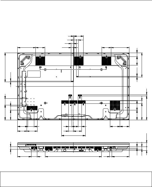
2.2.1 Heat dissipation
This unit has openings for effective ventilation at locations marked by arrows in the illustration below. The direction of the
arrows shows the direction of airflow. To allow proper dissipation of heat from the unit, do not cover any of these
openings.
(Unit : mm)
239 |
122 |
F |
|
381 11.5
|
F |
|
85 |
|
|
196 |
53.5 |
|
128 |
|
|
|
|
F |
|
134 |
85 |
|
122 |
137.5 |
34
180 78
|
9 |
122 |
|
|
|
|
40 |
25.5 |
|
|
|
|
30 |
|
|
|
|
|
32.5 |
122 |
239 |
|
|
F |
F |
F |
F |
49 |
|
|
|
|
|
115 |
318 |
Fan (3 in number) |
11.5 |
|
|
|
|
|
F |
|
18 |
|
|
|
|
|
|
|
|
|
|
|
123.5 |
38 |
|
|
|
|
|
215 |
313 |
|
|
|
|
|
128 |
||
F |
F |
F |
|
F |
|
|
|
46 |
46 |
130.5 |
122 |
|
|
|
65 |
109 |
|
|
|
|
|
314 |
|
|
|
51.5 |
|
|
|
|
|
|
|
|
|
|
|
|
|
|
50 |
|
742 |
30 |
|
22 |
34 |
|
|
|
228 |
|
|
||
Three fans draw off hot air from the unit. All openings not assisted by fans serve as air inlets. If the unit is hung from or embedded into a wall, special operating temperature limits and other limitations may apply. Refer to “2.4 Special installation (pg. 21)”.
14
Installation Conditions
2.2.2 Calculating heat quantity
As a courtesy to our customers, we have included the power formula to calculate the air conditioning needs. For power consumption, allow for 540 W ≠ 540 VA per unit.
Since most of the power consumed is transformed into heat, power consumption may be regarded as roughly equal to generated heat.
1 Conversion to calories [W] × 0.86 = [kcal/h]
Heat generated per display: 540 W × 0.86 = 465 kcal/h
2 Conversion to British Thermal Units [W] × 3.41 = [BTU/h]
Heat generated per unit: 540 W × 3.41 = 1842 BTU/h
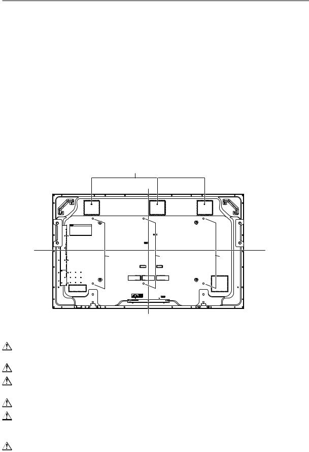
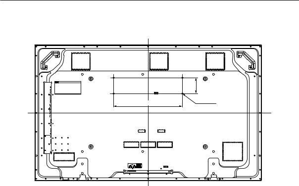
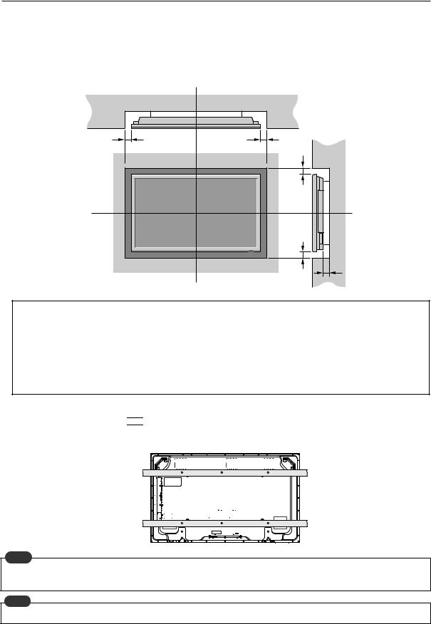
2.2.3 Product mounting holes
We recommend using mounting hardware available from Pioneer. If you use other mounting hardware items, mount them to the unit using the M8-bolt holes provided in the unit. Tighten the bolts with a torque between 50 and 80 kg/cm. Applying a torque beyond these limits may lead to internal component failure.
• Locations of useable mount holes are shown below.
Vent (fan)
|
|
Center line |
Holes |
Holes |
Holes |
Center line
Rear view diagram
Always use a minimum of 4 mounting holes, evenly distributed on opposite sides of both the horizontal and vertical center lines.
Use bolts that can be driven 12 to 18mm into holes.
Do not block or cover air outlets and openings for ventilation on the rear panel.
Take precautions to prevent soiling walls behind the product with exhaust air discharged from the air outlets.
This unit incorporates glass components. Install only on flat surfaces.
Always turn every bolt by hand 2 or 3 times and check to make sure it is straight, then tighten it using a tool. Do not over tighten bolts.
Do not use loctight or similar bonding products.
Please make sure that you use M8 (P=1.25) bolts (other types of bolt cannot be used).
15
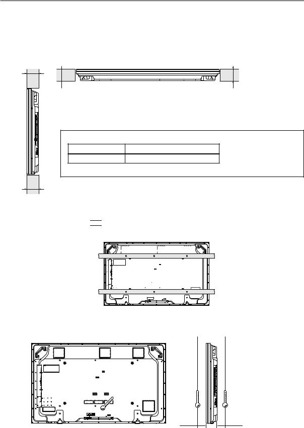
Installation Conditions
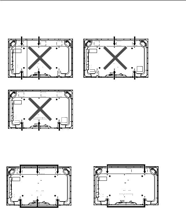
This unit is designed to be mounted using four bolt holes. For additional safety, we recommend securing it at four to six points on opposite sides of the horizontal and vertical center lines, as shown in the illustration below. Do not secure the unit at four points or at three points arranged in a single row, as shown below
Methods for securing - Unfavorable examples
Methods for securing - Favorable examples
A. Secured at six points |
B. Secured at four points |
16
Installation Conditions
2.2.4 Anchoring PC and similar apparatuses
102
445 |
M4x4 |
|
These holes are used to anchor and attach a PC or other apparatus.
They are M4 bolt holes x4, their horizontal pitch is 445mm and vertical pitch is 102mm.
Usage limitations:
•It is less than 10kg.
•If it covers a ventilation opening on the back cover of the plasma display, it is at least 10mm above the opening.
•The external temperature of the outside of the PC etc. that is installed is a maximum of 50°C at a surrounding temperature of 40°C or less.
The holes can also be used to help prevent the plasma display from falling over (Refer to “2.3.3 How to use the safety metal fittings and the screws for safety metal fittings (pg. 18)”)
But the plasma display cannot be anchored to and installed on a wall using only these holes.
An apparatus is installed only by a service man, so nobody except a serviceman may install one.
17
Installation Procedures
2.3 Installation Procedures
2.3.1 Transportation precautions
1 Any transportation of the unopened unit in its packaging should be done by two or more persons. To avoid injury or
damage, do not lift the package by its packing bands.
2When transporting or storing the unit, always position it vertically - never horizontally. Horizontal transportation or storage invalidates the product warranty.
3 In transportation or storage of products in original packing, never stack more than two units high. This warning is also indicated on the upper face of the carton.
4 For transportation or storage, observe the warnings and instructions on the upper face of the carton.
5 Plasma display is mode of glass. Please take precautions to prevent it from being damaged.
2.3.2 Transportation of the unpacked unit
If it needs to be moved, the unit should be moved by two or more persons.
 Caution
•Never move the unit by dragging it along the floor.
•Move the unit slowly, taking care to prevent scraping or striking the delicate front protective panel.
•In order to prevent adhesion of dust, remove the protective film only after all work and preparations for the installation
site, including clean-up following unpacking, are complete.
• Handles should not be removed or reattached by anyone other than the professional installation technician or service personnel.
• If handles must be removed due to specific installation conditions, the mounting screws should be stored carefully together with the handles. Also, when re-attaching the handle, be sure to completely tighten the screws to ensure safety
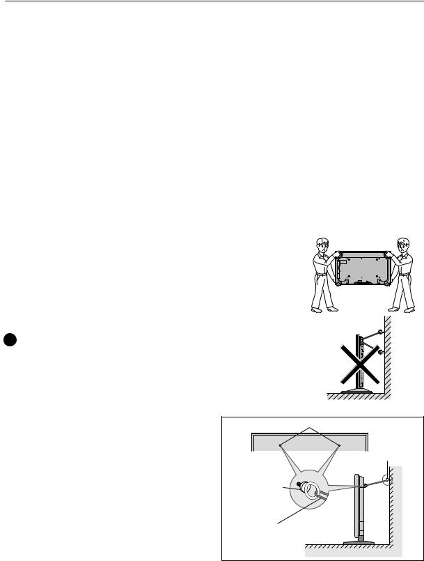
• When moving the display, it should always be carried by two persons holding the rear handles in the manner shown.
 No!
No!
• Never attempt to move the plasma display by holding only one of the handles.
• When installing the plasma display, do not use the handles as means of hanging the display; also do not use them as devices to prevent tipping over (see illustration).
2.3.3How to use the safety metal fittings and the screws for safety metal fittings
•These are fittings for fastening the unit to a wall to prevent tipping due to external shock when using the stand (optional). Fasten the safety fittings to the holes in the back of the monitor using the safety fitting mount screws.
•Be careful of the ropes when moving it.
•This device cannot be installed only on the display. Be sure to always install it using a stand specified by this company or a specialized unit.
•A serviceman installs this unit, so do not let anyone else install it. The person might be injured.
Screw hole
Screw or Hook etc. (Not supplied)
Safty metal fittings
Wall
Metal chain (Not supplied)
Table Top
18
Installation Procedures
2.3.4 Wiring
1)Connecting the power cable
•Check to make sure the electrical outlet is located so that it is easy to remove the power plug.
•Insert the power plug firmly. An incomplete connection causes noise.
•Attach the ferrite core (included with the product) to the power cord.
•For power source specifications, refer to 2.1 “Installation Site Requirements, Section 11) Power requirements (pg. 13)”, above.
2)Connecting signal cables
(1) Please refer to “p.3 of the instruction manual” for instructions on how to connect a PC or a video device.
(2) Important notes
•Use coaxial cables. As a rough guide, for video signals use 3C-2V cables for lengths up to 15 meters, and 5C-2V cables for lengths up to 30 meters. Use thicker cables for computer signals, since these signals are more likely to degrade: 5C-2V cables, for example, for 15-meter lengths. Generally, thicker cables will produce more reliable connections. You can also improve signal quality by minimizing cable length.
•Video cables plugged into video inputs and outputs close to dimmers, neon signs, air-conditioning units, or cables for wired broadcasts may occasionally deliver slightly corrupted images.
3)Processing wires
•In the case of permanent or long-term installation, please be careful to select cables of the correct length, considering the whole wiring route when doing this (this is not so important in the case of short-term installation such as with special events).
•Arrange and secure cables so that they will not be subject to direct load or physical force. For temporary installation, securing cables with string should be perfectly adequate. For permanent installations, secure by more reliable means.
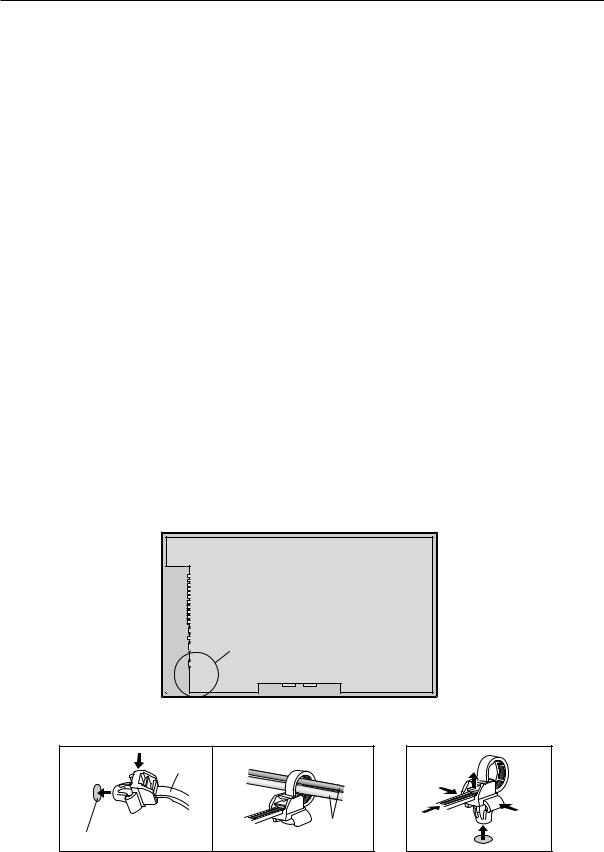
4)Cable Management
Using the cable clamps provided with the plasma display, bundle at the back of the unit the signal and audio cables connected to the display.
Back of the unit
mounting holes
To attach |
|
To detach |
1. |
clamp |
2. |
|
|


 cables mounting hole
19
Installation Procedures
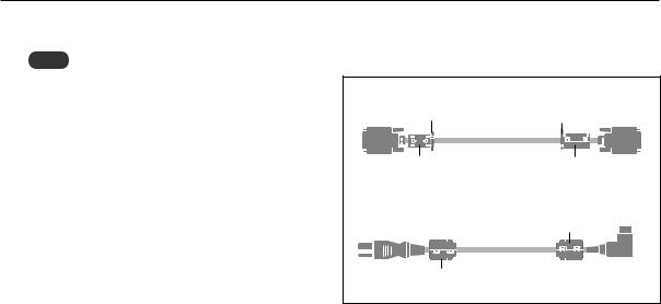
4)Attaching the ferrite cores
Note
When you connect a computer to this monitor, use an RGB cable including the ferrite core on both ends of the cable. And regarding DVI and power cable, attach the supplied ferrite cores. If you do not do this, this monitor will not conform to mandatory FCC standards.
Set the ferrite cores on both ends of the DVI cable (not supplied), and both ends of the power cable (supplied).
Close the lid tightly until the clamps click.
Use the band to fasten the ferrite core (supplied) to the DVI cable.
DVI cable (not supplied) |
|
|
band |
band |
Connector |
core (small) |
core (small) |
|
Power cable (supplied) |
core (large) |
|
|
||
core (large) |
|
|
20
Special Installation (Mounting to fittings)
2.4 Special Installation
The unit can be hung from or embedded in a wall, but such special installations impose additional limitations on operating temperatures and other operational factors.
Examine installation methods and the ambient conditions for your installation site, and refer to sections “2.1 Installation Site Requirements (pg. 12)”, ”2.2 Installation Conditions (pg. 14)”, “2.3 Installation Procedures (pg. 18)” in this manual.
Measurements discussed in this manual assume the following conditions:
•A 100 % white input is supplied.
•Sufficient aging has been completed.
Make all measurements under identical conditions. The aging period required for correct measurement will be about two and a half hours, depending on the space available at the installation site.
2.4.1 Mounting to fittings
Observe the following guidelines when mounting the unit to fittings. Notes 2 to 5 apply to all cases of mounting to fitting.
1 When mounting the unit, make sure that there are no objects around it within a distance of 300mm.
2 Any unit deformation/warping occurring as a result of installation should be less than 4 mm.
3 Never block or cover openings, aside from those shown as blocked in the illustrations on the following page.
4 The strength of the fittings should be adequate to bear the weight of the display.
5 Take precautions to avoid sharply bending the power cable.
Operating environment for standard installation
• Ambient Temperature: 0 to 40 °C (example 1)
Operating environment for vertical installation
0 to 40 °C (vertical installation: example 2)
The operating temperature restrictions for the speaker system (PDP-S29-LR) are the same regardless of installation position.
Standard installation |
Vertical installation |
|
Example 1 |
Example 2 |
35 mm or less |
|
|
|
|
35 mm or |
|
|
less |
|
21
Special Instruction (Hanging on the wall)
2.4.2 Hanging on the wall
Carefully read the following before attempting to hang the unit on a wall, and observe the various limitations specified below. Be sure to mount the unit so that twisting, bending, or any other deformation does not exceed 4 mm.
Ventilation Requirements for enclosure mounting
To allow heat to disperse, leave space between surrounding objects as shown on the diagram below when installing.
|
Wall |
D |
D |
Wall
B
C
A
Operating temperature restrictions
Standard single-unit installation
|
Distance from wall (A) |
B |
C |
D |
Ambient temperature |
|
50 mm or more |
50 mm or more |
50 mm or more |
50 mm or more |
0 to 40°C |
|
|
|
|
|
|
Requirements when used with PDP-S29-LR speaker system |
|
||||
|
|
|
|
|
|
|
Requirements are the same as those for standard single-unit installation. |
|
|||
|
However, dimensions refer to the distance between the speaker and the wall |
|
|||
|
|
|
|
|
|
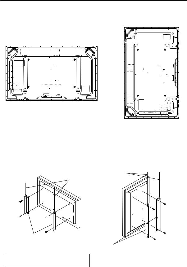
Methods of Securing: Basic methods of securing are shown below. Avoid blocking or covering areas aside from those indicated by 
 . Before attaching the unit to fittings, double-check that the thickness and height of the fittings, and the number of fixing bolts is correct. (Also refer to 2.4.1 “Mounting to fittings (pg. 21)”.)
Note
Heated air is drawn off from the interior of the unit by fans. Before installation, consider the heat resistance of the wall or other surfaces behind the unit. Exhaust temperatures can be 30 °C higher than the outside temperature.
Note
For wall-mounting, do not bundle the cables in a way that will obstruct ventilation.
22
Special Installation (Embedding in the wall)
2.4.3 Embedding in the wall
Carefully read the following before trying to embed the unit in a wall, and make sure to observe all the limitations specified below.
Be sure to mount the unit so that twisting, bending, or other deformation of the unit does not exceed 4 mm.
(1)Embedding in walls with space provided behind the unit (With no obstructions within a distance of 300 mm from the back surface of the unit).
A |
X (Front of the unit) |
|
|
|
|
A |
Y (Rear of the unit) |
A |
|
|
<Viewed from Above>
Operating Temperature Restrictions
|
Temperature in space X and Y |
A: 0 to 300 mm |
0 to 40 °C |
* The same operating temperature restrictions apply to the speaker system (PDP-S29-LR).
A
<Viewed from the Right Side>
Methods of Securing: Basic methods of securing are shown below. Avoid blocking or covering areas aside from those indicated by 
 . Before attaching the unit to fittings, double-check that the thickness and height of the fittings, and the number of fixing bolts is correct. (Also refer to 2.4.1 “Mounting to fittings (pg. 21)”.)
Temperature Measurement Points (Illustration for reference purposes)
 : Thermometer (temperature measurement point)
50mm |
50mm |
•Make measurements at a distance of 50 mm from the unit, without directly subjecting the thermometer to fan exhaust.
•For spaces where temperature fluctuations are likely, gather additional measurement points for an adequate data set.
23
Special Installation (Ceiling suspension (with wires))
2.4.4 Ceiling suspension (with wires)
When suspending it from a ceiling with wire, the unit must be attached at four or more points with these points distributed symmetrically on both sides of the vertical and horizontal center lines.
Attach this fan on the left side


 A
A 

 B
B


A 


 B
B
When suspending from a ceiling with wire, use the brackets shown below to prevent concentrating loads on the upper two fixing points.
For additional safety, secure the wires to separate fittings or parts of the ceiling.
Use mounting screws of material stronger than soft steel, and use hexagonal bolts.
Use wires adequate for the combined weight of the unit 61.0 kg and the weight of the support brackets.
 No!
No!
When installing the plasma display, do not use the handles as means of hanging the display.
Wires
Wires
Screws 

Brackets
 Screws
Brackets
Operating Temperature Restrictions
• Ambient temperature: 0 to 40 °C
24
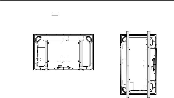
Special Installation (Ceiling suspension (with wires))
Methods of Securing: Basic methods of securing are shown below. Avoid blocking or covering areas aside from those indicated by 
 . Before attaching the unit to fittings, double-check that the thickness and height of the fittings, and the number of fixing bolts is correct. (Also refer to 2.4.1 “Mounting to fittings
(pg. 21)”.)
Vertical suspension
25
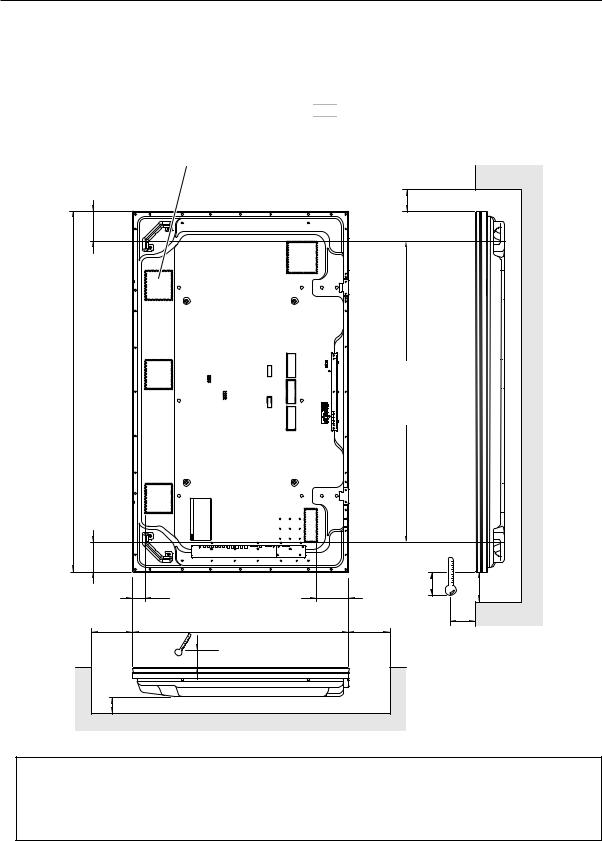
Special Installation (Hanging on the wall (lengthwise))
2.4.5 Hanging on the wall (lengthwise)
Carefully read the following before attempting to mount the unit on the wall, and observe the various limitations specified
below.
Be sure to mount the unit so that twisting, bending, or any other deformation does not exceed 4 mm.
1470
Shaded areas 
 indicate attachment points for mounting hardware.
 : Thermometer (temperature measurement point)
Attach this fan on the left side
B
122
Avoid blocking or covering this area on the upper and lower sides.
122
49 |
|
128 |
25 |
C |
|
|
|
||
D |
880 |
|
D |
10 |
|
|
10 |
A |
Operating Temperature Restrictions
Distance from wall (A) |
B |
C |
D |
Ambient temperature |
50 mm or more |
50 mm or more |
50 mm or more |
50 mm or more |
0 to 40 °C |
|
|
|
|
|
26
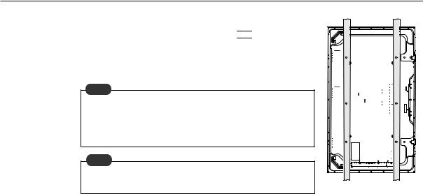
Special Installation (Hanging on the wall (lengthwise))
Methods of Securing: Basic methods of securing are shown right. Avoid blocking or covering areas aside from those indicated by 
 . Before attaching the unit to fittings, double-check that the thickness and height of the fittings, and the number of fixing bolts is correct. (Also refer to 2.4.1 “Mounting to fittings (pg. 21)”.)
Note
Heated air is drawn off from the interior of the unit by fans. Before installation, consider the heat resistance of the wall or other surfaces behind the unit. Exhaust temperatures can be 30 °C higher than the outside temperature.
Note
For wall-mounting, do not bundle the cables in a way that will obstruct ventilation.
27
 Loading...