


Speaker System Enceintes acoustiques Lautsprechersystem Sistema di diffusori Luidsprekersysteem Sistema de altavoces
PDP-S37
Operating Instructions Mode d’emploi Bedienungsanleitung Istruzioni per l’uso Gebruiksaanwijzing Manual de instrucciones
English
Thank you for buying this Pioneer product.
Please read through these operating instructions before using your speaker system so you will know how to make the most of its performance. After you have finished reading the instructions, put them away in a safe place for future reference.
WARNING:
Handling the power cord on this product or cords associated with accessories sold with the product will expose you to lead, a chemical known to the State of California and other governmental entities to cause cancer and birth defects or other reproductive harm.
Wash hands after handling.
CAUTION
This product is designed exclusively for use with the Pioneer Plasma Display. For more information on compatibility, please consult with your nearest Pioneer authorized dealer or service center.
BEFORE USE
÷The nominal impedance of this speaker system is 8 ohms.
÷In order to prevent damage to the speaker system resulting from input overload, please observe the following precautions:
÷Do not supply power to the speaker system in excess of the maximum permissable input. This can result in damage or a possible fire hazard.
÷When connecting or disconnecting pin-plugs, be sure that amplifier power is OFF.
÷When using a graphic equalizer to emphasize loud sounds of a high frequency range, do not use excessive amplifier volume.
÷Do not force a low-powered amplifier to produce a loud volume of sound (the amplifier’s harmonic distortion will be increased, and you may damage the speaker).
÷Please handle the speakers with sufficient care, as the grille net and the cabinet can become damaged or broken when they are subjected to strong external impacts.
÷Placing a CRT computer screen or CRT monitor near to the speakers may result in interference or color distortion. If this happens, distance the monitor from the speakers.
Installation
÷Consult your dealer if you encounter any difficulties with this installation.
÷Pioneer is not liable for any damage resulting from improper installation, improper use, modification, or natural disasters.
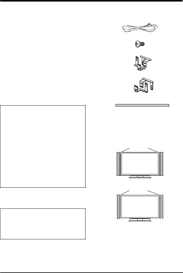
CHECKING THE ACCESSORIES
7Speaker Cable × 2
7Speakers Mounting Screw (M5 × 10 mm: Black) × 16
7Speaker Mounting Bracket
For LEFT-TOP
For LEFT-BOTTOM
For RIGHT-TOP
For RIGHT-BOTTOM
7Padding Strip × 2
(For Flush mounting)
When speakers are mounted Flush, they are affixed to the side of the speaker as a buffer.
7Operating Instructions × 1
There are two ways to mount these speakers, either Air mount or Flush mount.
7Air mount
There is a gap of air of about 15 mm between the speakers
and the display.
Speakers
7Flush mount
The speakers are direct against the display.
Speakers
 CAUTION:
÷Do not place force on the speakers’ front panel grille net, or stick your finger or other object into the front of the speaker, since you may damage the grille net or speaker unit itself.
÷Do not use these speakers with anything other than the Plasma Display. Doing so may result in damage or fire.
2
English
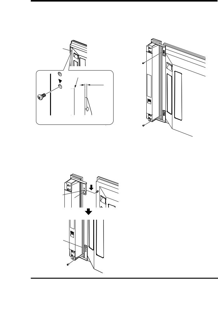
MOUNTING THE SPEAKERS TO |
Flush mounting |
||
YOUR PLASMA DISPLAY |
Screw Holes for |
||
|
Warning |
Flush mounting |
|
|
(2 on inside) |
||
÷ Attach the Plasma Display to the stand before installing |
|||
|
|||
|
the speakers. See the Operating Instructions packed |
|
|
|
together with the stand for how to assemble the stand. |
Screw Holes for |
|
÷ |
When mounting the speakers, only use the screws |
||
|
enclosed. Using any screws other than those enclosed |
Flush mounting |
|
|
may cause the speakers to come loose and fall. |
(2 on inside) |
|
÷ |
When mounting the speakers, be sure to tighten the |
|
|
|
screws securely so they will not come loose. |
|
|
÷Do not lift up the display by the speakers. A speaker may come off, so carry the display by holding it by the bottom
and its handle. |
|
|
|
÷ If you wish to change from Flush mounting to Air mounting |
|
|
|
or vice versa: |
|
|
|
Remove the speaker mounting brackets from the |
|
|
|
speakers and the display and remount them from the |
|
Speaker Mounting |
|
beginning. |
|
||
|
Brackets |
||
|
|
||
1 Attaching the Speaker Mounting |
|
(For RIGHT-TOP) |
|
Speaker Mounting Brackets |
(The skinny slot is |
||
Brackets to the Speakers |
used for mounting to |
||
(For RIGHT-BOTTOM) |
the top.) |
||
There is a left speaker and a right speaker. When you |
|||
Place the speaker so its terminals (bottom) |
|||
are mounting them, check the label on the back to get |
|||
them right. |
are facing you. (Example of right speaker) |
||
|
|
||
There are top and bottom speaker mounting brackets |
2 If mounting the speakers Flush, affix |
||
for both the left and the right speaker. Attach the |
the padding strip to the side of the |
||
appropriate bracket to the top and the bottom on the |
speakers (side that touches the |
||
back of the speakers with the enclosed screws. (See |
|||
display). |
|
||
Diagram) |
|
||
The diagram depicts the mounting of the right |
Use the enclosed padding strips to buffer the speakers |
||
speaker. The left speaker mounts in the same way. |
when mounting them Flush. Peel off the protective strip |
||
|
and affix to the side of the speakers. |
||
Air mounting
Screw Holes for Air mounting (2 on outside)
Screw Holes for Air mounting (2 on outside)
|
Speaker Mounting |
|
|
Brackets |
|
|
(For RIGHT-TOP) |
|
Speaker Mounting Brackets |
(The skinny slot is used |
|
for mounting to the top.) |
||
(For RIGHTBOTTOM) |
||
|
Padding Strip
(10) |
Where to position the padding strip
Place the speaker so its terminals (bottom) are facing you. (Example of right speaker)
English
3
English
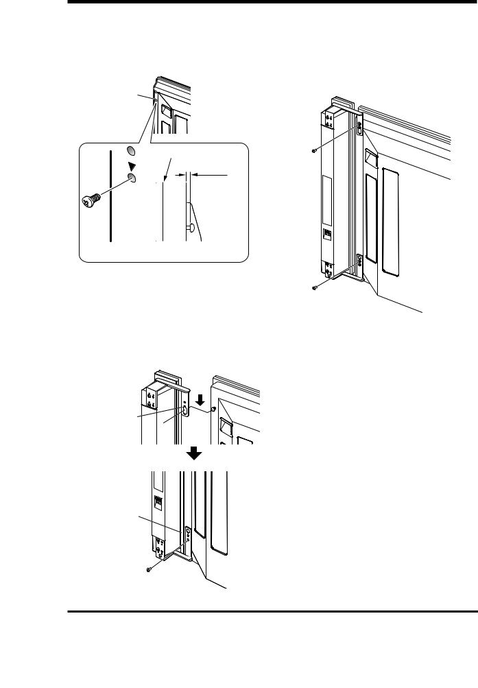
3Screw an enclosed screw into the speaker mounting hole (lower of the
two) at the top, back of the display.
Do not tighten it all the way yet. Leave it loose, with about 5 mm left to tighten.
Speaker Mounting Hole
Top, Back of
Display
Top of Display
5 mm
Leave a space of about 5 mm
4Hang the speaker mounting bracket on the screw you installed at the top by passing the wide part over it and lowering into the slot; screw in the
lower screw temporarily.
After passing the wide part of the hole of the speaker mounting bracket (top) over the screw, lower the speaker onto it.
After passing the wide part of the hole over the screw, lower the speaker.
Tighten the bottom speaker mounting bracket to the display temporarily (one place bottom).
5Adjust the position of the speaker and then fix the upper and lower screws firmly.
6Tighten the two screws, at the top and bottom for each speaker (total of four screws), thus fixing the speakers to the display.
4
English
CONNECTION TO A PLASMA DISPLAY
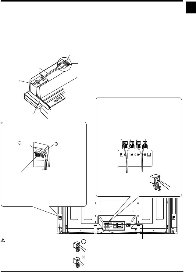
CONNECTING THE SPEAKERS
1 Pass the speaker cables through the hole in the speaker mounting bracket. 2 Connect the speaker cables to the speaker.
3 Press the speaker cables into the groove of the bracket. 4 Connect the speaker cables to the display.
Speaker Terminal
2
Speaker Cable
3
1
Groove
Connecting your Speaker Cables (to the speaker)
(black) |
(red) |
|

 Gray Line
Connecting your Speaker Cables (to the display)
Connect the cables correctly with respect to the polarity of the Plasma Display and the speaker terminals, that is, ª cable to ª terminals and · cable to · terminals. To do so, connect the cable with the gray line to the ª terminals and the white cable to the · terminals.
Gray Line White White Gray Line
White |
|
|
Push the lever, insert the end of the speaker cable |
÷ Press the lever and insert the |
|
into the hole, and release the lever. |
end of the cable. |
|
|
÷ When you release the lever, |
|
Pay attention to the polarity of the speaker terminals |
it clamps onto the speaker |
|
cable. |
||
when making connections. (The gray line represents |
||
|
||
the ª terminal) |
|
Warning |
4 |
|
If you insert the speaker cable too far so that |
||
|
||
the insulation is touching the speaker |
|
|
terminal, you may not get any sound. |
|
English
5
English
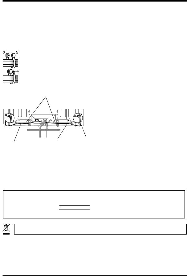
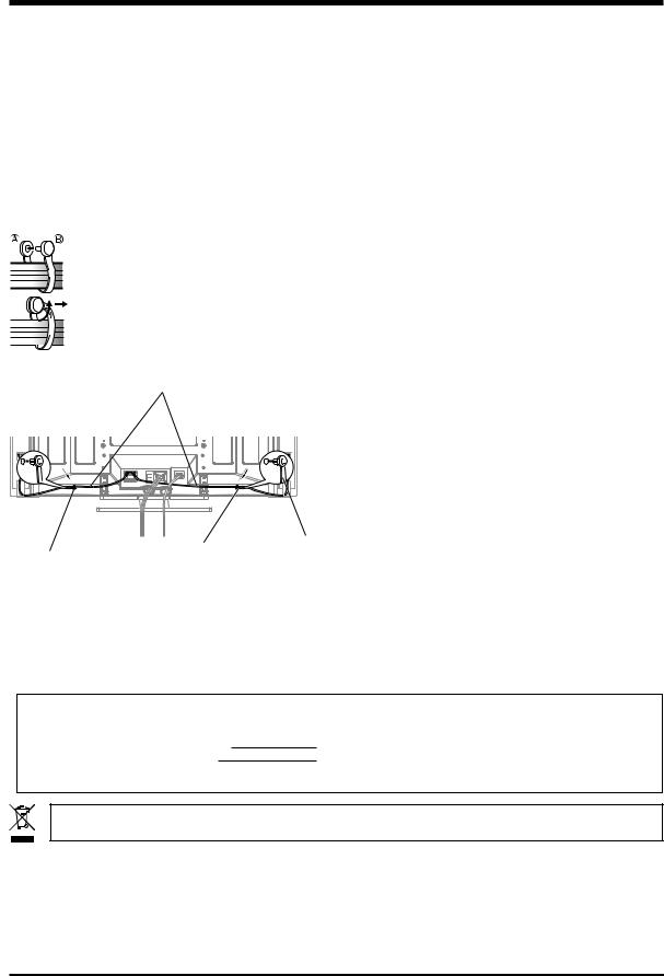
HOW TO ROURE CABLES
Speed clamps are included with the Plasma Display for tidying your cables and keeping extra cable length out of the way.
Attach speed clamps at the direction of the running cables.
*When the Pioneer stand, sold separately, is not used, use the two holes that are marked with arrows in the diagram (  ) as the holes for attaching speed clamps.
Using Speed Clamps
Wrap the speed clamp around the bundled cables and press B into hole A.
To remove a speed clamp, use pliers to twist it 90° and then pull it out. (This may result in weakening or damaging the clamp.)
Speaker Cable
∞ Rear of Display 
Speed Clamp
Speed
Speed Clamp Mounting Hole Clamp
Mounting Hole
CABINET MAINTENANCE
÷Use a polishing cloth or dry cloth to wipe off dust and dirt.
÷When the cabinet is very dirty, wipe with a soft cloth moistened with water-diluted cleanser; then wipe again with a dry cloth. Do not use furniture wax or cleaners. They may damage the surface of the cabinet.
÷Never use thinner, benzine, insecticide sprays and other chemicals on or near the cabinets, since these will corrode the surfaces.
÷When a chemical cloth is used, read the cautions for the chemical cloth carefully.
SPECIFICATIONS
Cabinet: Bass-reflex type
Used speakers (two-way system):
Woofer (for low tones) ................ |
4.8 × 13 cm cone type |
Tweeter (for high tones) |
........... 2.5 cm semidome type |
Nominal impedance ..................................................... |
8 Ω |
Frequency Range ..................................... |
70 to 30,000 Hz |
Sensitivity (1 w, 1 m) ................................................ |
81 dB |
Permissible input : |
|
Max. input .............................................................. |
13 W |
Rated input .............................................................. |
4 W |
Crossover frequency ................................................ |
3 kHz |
External Dimensions ...... |
76.5 (W) × 632 (H) × 92 (D) mm |
Weight ..................................................................... |
1.5 kg |
Accessory parts (for 2 speakers) |
|
............................................................ |
Speaker cable × 2 |
...................................................... |
Screw (M5 × 10) × 16 |
............................................................................. |
Bracket |
|
LEFT-TOP × 1 |
|
LEFT-BOTTOM × 1 |
|
RIGHT-TOP × 1 |
|
RIGHT-BOTTOM × 1 |
.............................................................. |
Padding strip × 2 |
.............................................. |
Operating Instructions × 1 |
NOTE:
Specifications and design subject to possible modification without notice, due to improvements.
IMPORTANT NOTICE – RECORD THE MODEL NUMBER AND SERIAL NUMBERS OF THIS EQUIPMENT BELOW. THE NUMBERS ARE ON THE REAR.
MODEL NO.
SERIAL NO.
KEEP THESE NUMBERS FOR FUTURE USE.
D1-4-2-6-2_En
If you want to dispose this product, do not mix it with general household waste. There is a separate collection system for used electronic products in accordance with legislation that requires proper treatment, recovery and recycling.
Private households in the 25 member states of the EU, in Switzerland and Norway may return their used electronic products free of charge to designated collection facilities or to a retailer (if you purchase a similar new one).
For countries not mentioned above, please contact your local authorities for the correct method of disposal.
By doing so you will ensure that your disposed product undergoes the necessary treatment, recovery and recycling and thus prevent potential negative effects on the environment and human health.
Published by Pioneer Corporation.
Copyright © 2005 Pioneer Corporation.
All rights reserved.
6

English
English
7
Français
Merci pour votre achat de cet appareil Pioneer.
Veuillez lire attentivement toutes le mode d’emploi avant d’utiliser vos enceintes acoustiques de façon à pouvoir en tirer le meilleur profit. Après lecture complète du livret d’instructions de fonctionnement, le ranger dans un endroit sûr afin de pouvoir vous y reporter facilement en cas de besoin lors de l’utilisation des l’enceintes acoustiques.
ATTENTION
Ce produit est conçu exclusivement pour l’utilisation avec un écran plasma Pioneer. Pour de plus amples informations sur la compatibilité, veuillez vous adresser au distributeur ou au centre de service Pioneer agréé le plus proche.
AVANT USAGE
÷L’impédance nominale de ces enceintes acoustiques est de 8 Ω.
÷Afin d’éviter d’endommager les enceintes acoustiques, suite à une surcharge à l’entrée, veuillez observer les précautions suivantes:
÷Ne pas fournir aux enceintes une alimentation supérieure à la valeur maximale admise, sinon l’appareil risque d’être endommagé ou un incendie pourrait éclater.
÷En connectant ou en déconnectant les fiches à plots, s’assurer que l’alimentation de l’amplificateur est coupée.
÷En utilisant un égalisateur graphique pour accentuer les sons forts dans la plage des hautes fréquences, ne pas régler l’amplificateur à un volume excessif.
÷Ne pas contraindre un amplificateur de faible puissance à fonctionner à un volume sonore poussé (la distorsion harmonique de l’amplificateur sera accrue, ce qui risquerait d’endommager les enceintes).
÷Manipuler les enceintes avec suffisamment de soin, car autrement, l’enjoliveur frontal et le coffret risqueraient d’être endommagés ou hors d’usage en les soumettant à des chocs externes exagérés.
÷Si un écran d’ordinateur à écran cathodique (CRT) ou un moniteur à écran cathodique (CRT) est placé à proximité des enceintes, il risque de présenter des interférences ou une dénaturation des couleurs. Dans ce cas, éloignez le moniteur des enceintes.
Installation
÷En cas de difficultés, veuillez consulter votre revendeur.
÷Pioneer ne saurait être tenu responsable d’aucun dommage résultant d’une installation ou d’une utilisation incorrecte de ce produit, de sa modification ou encore de catastrophes naturelles.
VÉRIFICATIONDESACCESSOIRES
7Câbles d’enceinte × 2
7Vis pour montage des enceintes (M5 × 10mm : Noires ) × 16
7Supports pour montage des enceintes
Pour côté supérieur gauche
Pour côté inférieur gauche
Pour côté supérieur droit
Pour côté inférieur droit
7Rubans de rembourrage × 2
(Pour montage à ras)
Quand les enceintes sont montées à ras, chacun des ces rubans doit être collé sur le côté d’une enceinte comme tampon.
7Mode d’emploi × 1
Il y a deux façons de monter ces enceintes, montage à l’écart ou montage à ras.
7Montage à l’écart
Il y a un espace vide d’environ 15 mm entre les enceintes
et l’écran.
Enceintes
7Montage à ras
Les enceintes sont contre l’écran.
Enceintes
 ATTENTION:
÷N’appuyez pas sur la grille souple du panneau avant de l’enceinte et n’enfoncez pas le doigt ou un objet dans l’avant de l’enceinte, car ceci pourrait endommager la grille souple, voire le haut-parleur proprement dit.
÷N’utilisez pas ces enceintes avec un produit autre qu’un écran plasma. Cela pourrait donner lieu à un endommagement ou à un incendie.
8

FIXATION DES ENCEINTES À L’ÉCRAN PLASMA
 Avertissement
÷Avant de procéder à l’installation des enceintes, fixez l’écran plasma sur son socle. Se référer au mode d’emploi fourni avec le socle pour la procédure d’assemblage.
÷Lors du montage des enceintes, utilisez seulement les vis fournies. Si vous utilisez des vis autres que celles fournies, les enceintes peuvent se détacher et tomber.
÷Lors du montage des enceintes, veillez à bien serrer les vis de manière qu’elles ne se détachent pas.
÷Ne soulevez pas l’écran en le tenant par les enceintes. Les enceintes pourraient se détacher; toujours transporter l’écran en le tenant par la base et sa poignée.
÷Si vous souhaitez passer du montage à ras au montage à l’écart ou vice versa:
Enlevez les supports de montage des enceintes et de l’écran puis remettez-les en place à partir du début de la procédure.
1 Fixation des supports de montage aux enceintes
Il y a une enceinte gauche et une enceinte droite. Quand vous les montez, vérifier l’étiquette située au dos pour les différencier.
Il y a des supports de montage supérieur et inférieur pour chacune des enceintes gauche et droite. Avec les vis fournies, fixez les supports appropriés au dos de chaque enceinte. (Voir l’illustration)
L’illustration représente le montage de l’enceinte droite. L’enceinte gauche se monte de la même façon.
Montage à l’écart
Trous de vis pour montage à l’écart (2 trous sur l’extérieur)
Trous de vis pour montage à l’écart
(2 trous sur l’extérieur)
Français
Montage à ras
Trous de vis pour montage à ras
(2 trous sur l’intérieur)
Trous de vis pour montage à ras
(2 trous sur l’intérieur)
Support de montage d’enceinte
(Pour côté inférieur droit)
Français
Support de montage d’enceinte
(Pour côté supérieur droit) (Le petit trou s’utilise pour la fixation à la partie supérieure.)
Posez l’enceinte de manière que ses bornes (situées en bas) soient face à vous. (Exemple de l’enceinte droite)
2Si vous montez les enceintes à ras, collez le ruban de rembourrage sur le
côté (côté qui touche l’écran).
Utilisez les rubans de rembourrage fournis pour protéger les enceintes quand vous les montez à ras. Enlevez le film de protection et collez le ruban sur le côté de l’enceinte.
Ruban de rembourrage
(10) |
Support de montage
d’enceinte
(Pour côté inférieur droit) Où positionner le ruban de rembourrage Posez l’enceinte de manière que ses bornes
(sutuées en bas) soient face à vous. (Exemple de l’enceinte droite)
9
Français
3Vissez une des vis fournies dans le trou de fixation inférieur (il y a deux trous) se trouvant à la partie
supérieure du dos de l’écran.
Ne serrez pas encore cette vis au maximum. Laissez un espace d’environ 5 mm.
5Ajustez la position de l’enceinte, puis serrez fermement les vis supérieures et inférieures.
6Montez deux autres vis, une en haut et une en bas (total de quatre vis), pour fixer l’enceinte à l’écran.
Trou de fixation |
Partie |
d’enceinte |
supérieure du |
|
dos de l’écran |
Haut de l’écran
5 mm
Laissez un espace d’environ 5 mm
4Accrochez le support de montage d’enceinte à cette vis en faisant passer la partie large du trou sur la tête puis en l’abaissant; serrez alors
la vis inférieure provisoirement.
Après avoir fait passer la partie large du trou du support de montage d’enceinte (supérieur) sur la vis, abaissez l’enceinte.
Après avoir fait passer la partie large du trou sur la vis, abaissez l’enceinte.
Fixez provisoirement (un endroit, inférieur) le support de montage d’enceinte inférieur à l’écran.
10
Français
CONNEXION À UN ÉCRAN PLASMA
CONNEXION DES ENCEINTES
1 Faites passer le câble d’enceinte dans le trou du support de montage d’enceinte. 2 Connectez le câble à l’enceinte.
3 Ajustez le câble d’enceinte dans la rainure du support. 4 Connectez le câble d’enceinte à l’écran.
Borne d’enceinte
2
Câble d’enceinte
3
1
Rainure
Connexion des câbles d’enceinte (aux enceintes)
(Noir) |
(Rouge) |
|

 Trait gris
Connexion des câbles d’enceinte (à l’écran)
Connectez les câbles correctement par rapport à la polarité des bornes de l’écran plasma et des enceintes, c’est-à-dire, câbles ª aux bornes ª et câbles · aux bornes ·. Pour ce faire, connectez le câble portant le trait gris aux bornes ª et le câble blanc aux bornes ·.
Trait gris Blanc Blanc Trait gris
Blanc |
|
|
Appuyez sur le levier, insérez l’extrémité du câble |
÷ Appuyez sur le levier et |
|
d’enceinte dans le trou, puis relâchez le levier. |
insérez l’extrémité du câble. |
|
|
÷ Quand vous relâchez le levier, |
|
Lors de la connexion, faites attention à la polarité |
la borne serre sur le câble |
|
d’enceinte. |
||
des bornes d’enceinte. (Le trait gris correspond à la |
||
|
||
borne ª ) |
|
Avertissement |
4 |
|
Si vous insérez le câble d’enceinte trop loin |
||
|
||
au point que l’isolant touche la borne |
|
|
d’enceinte, il est possible qu’aucun son ne |
|
|
soit obtenu. |
|
Français
11
Français
COMMENT FAIRE CHEMINER LES CÂBLES
Des colliers rapides et des colliers à oeil sont fournis avec le système pour permettre la mise en faisceau des câbles. Après avoir constitué les faisceaux de câbles, procédez comme il est dit ci-dessous pour les faire cheminer.
Fixez les colliers rapides sur le passage des câbles installés.
*Quand le support Pioneer, vendu séparément, n’est pas utilisé, utilisez les deux trous indiqués par des flèches sur l’illustration (  ) pour la fixation des colliers rapides.
Utilisation de colliers rapides
Enroulez le collier autour des câbles en faisceau puis enfoncez B dans le trou A.
ENTRETIEN DU COFFRET
÷Utiliser un chiffon à polir ou un chiffon sec pour essuyer la poussière et éliminer les salissures.
÷Si le coffret est très sale, le frotter avec un chiffon doux imbibé de liquide à nettoyer dilué d’eau. Ensuite, essuyer à nouveau avec un chiffon sec. Ne pas utiliser de cire à meuble ou de produits de nettoyage corrosifs. Ils risqueraient d’endommager la surface du coffret.
÷Ne jamais utiliser non plus de diluant, de benzine, d’insecticides en vaporisateur et autres produits chimiques sur le coffret ou à proximité, car ils risquent de corroder les surfaces.
÷Si l’on utilise un chiffon chimique, lire et observer attentivement les précautions à prendre pour son usage adéquat.
SPECIFICATIONS
Pour enlever un collier rapide, utilisez des pinces pour le tourner de 90° puis le tirer vers l’extérieur. (Ceci peut affaiblir ou endommager le collier.)
Câble d’enceinte
∞ Dos de l’écran
Trou de fixation de
Collier
Trou de fixation collier rapide rapide de collier rapide
Coffret : Type bass-reflex
Haut-parleurs utilisés (système à double voie) :
Haut-parleur de graves |
....... |
Type à cône de 4,8 × 13 cm |
Haut-parleur d’aigus ......... |
Type à semi-dôme de 2,5 cm |
|
Impédance nominale ................................................... |
|
8 Ω |
Plage de fréquences ................................. |
|
70 à 30.000 Hz |
Sensibilité (1 w, 1 m) ............................................... |
|
81 dB |
Entrée admissible : |
|
|
Entrée max. ............................................................ |
|
13 W |
Entrée nominale ...................................................... |
|
4 W |
Fréquence de recouvrement ................................... |
3 kHz |
|
Encombrement ................. |
76,5 (L) × 632 (H) × 92 (P) mm |
|
Poids ........................................................................ |
|
1,5 kg |
Pièces accessoires (pour 2 enceintes)
...................................................... Câbles d’enceinte × 2
............................................................ Vis (M5 x 10) × 16
............................................................................ Support Supérieur gauche × 1 Inférieur gauche × 1 Supérieur droit × 1 Inférieur droit × 1
.............................................. Ruban de rembourrage × 2
.......................................................... Mode d'emploi × 1
REMARQUE:
Les spécifications et la finition sont susceptibles d’être modifiées sans préavis en vue de l’amélioration.
AVIS IMPORTANT – VEUILLEZ REPORTER CI-DESSOUS LES NUMEROS DE MODELE ET DE SERIE DE L’EQUIPEMENT. CES NUMEROS APPARAISSENT A L’ARRIERE.
Nº MODELE :
Nº SERIE :
VEUILLEZ CONSERVER CES NUMEROS EN VUE DE FUTURES UTILISATIONS.
Si vous souhaitez vous débarrasser de cet appareil, ne le mettez pas à la poubelle avec vos ordures ménagères. Il existe un système de collecte séparé pour les appareils électroniques usagés, qui doivent être récupérés, traités et recyclés conformément à la législation.
Les habitants des 25 états membres de l’UE, de Suisse et de Norvège peuvent retourner gratuitement leurs appareils électroniques usagés aux centres de collecte agréés ou à un détaillant (si vous rachetez un appareil similaire neuf).
Dans les pays qui ne sont pas mentionnés ci-dessus, veuillez contacter les autorités locales pour savoir comment vous pouvez vous débarrasser de vos appareils. Vous garantirez ainsi que les appareils dont vous vous débarrassez sont correctement récupérés, traités et recyclés et préviendrez de cette façon les impacts néfastes possibles sur l’environnement et la santé humaine.
Publication de Pioneer Corporation. © 2005 Pioneer Corporation.
Tous droits de reproduction et de traduction réservés.
12
 Loading...