


Speaker System Enceintes acoustiques Sistema de altavoces
PDP-S36
Operating Instructions Mode d’emploi
Manual de instrucciones
English
Thank you for buying this Pioneer product.
Please read through these operating instructions before using your speaker system so you will know how to make the most of its performance. After you have finished reading the instructions, put them away in a safe place for future reference.
WARNING:
Handling the power cord on this product or cords associated with accessories sold with the product will expose you to lead, a chemical known to the State of California and other governmental entities to cause cancer and birth defects or other reproductive harm.
Wash hands after handling.
CAUTION
This product is designed exclusively for use with the Pioneer Plasma Display. For more information on compatibility, please consult with your nearest Pioneer authorized dealer or service center.
BEFORE USE
÷The nominal impedance of this speaker system is 8 ohms.
÷In order to prevent damage to the speaker system resulting from input overload, please observe the following precautions:
÷Do not supply power to the speaker system in excess of the maximum permissable input. This can result in damage or a possible fire hazard.
÷When connecting or disconnecting pin-plugs, be sure that amplifier power is OFF.
÷When using a graphic equalizer to emphasize loud sounds of a high frequency range, do not use excessive amplifier volume.
÷Do not force a low-powered amplifier to produce a loud volume of sound (the amplifier’s harmonic distortion will be increased, and you may damage the speaker).
÷Please handle the speakers with sufficient care, as the grille net and the cabinet can become damaged or broken when they are subjected to strong external impacts.
÷Placing a CRT computer screen or CRT monitor near to the speakers may result in interference or color distortion. If this happens, distance the monitor from the speakers.
Installation
÷Consult your dealer if you encounter any difficulties with this installation.
÷Pioneer is not liable for any damage resulting from improper installation, improper use, modification, or natural disasters.
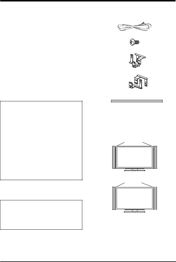
CHECKING THE ACCESSORIES
7Speaker Cable × 2
7Speakers Mounting Screw (M5 × 10 mm: Black) × 16
7Speaker Mounting Bracket
For LEFT-TOP
For LEFT-BOTTOM
For RIGHT-TOP
For RIGHT-BOTTOM
7Padding Strip × 2
(For Flush mounting)
When speakers are mounted Flush, they are affixed to the side of the speaker as a buffer.
7Operating Instructions × 1
There are two ways to mount these speakers, either Air mount or Flush mount.
7Air mount
There is a gap of air of about 15 mm between the speakers
and the display.
Speakers
7Flush mount
The speakers are direct against the display.
Speakers
 CAUTION:
÷Do not place force on the speakers’ front panel grille net, or stick your finger or other object into the front of the speaker, since you may damage the grille net or speaker unit itself.
÷Do not use these speakers with anything other than the Plasma Display. Doing so may result in damage or fire.
2
English
MOUNTING THE SPEAKERS TO |
Flush mounting |
||
YOUR PLASMA DISPLAY |
Screw Holes for |
||
|
Warning |
Flush mounting |
|
|
(2 on inside) |
||
÷ Attach the Plasma Display to the stand before installing |
|||
|
|||
|
the speakers. See the Operating Instructions packed |
|
|
|
together with the stand for how to assemble the stand. |
Screw Holes for |
|
÷ |
When mounting the speakers, only use the screws |
||
|
enclosed. Using any screws other than those enclosed |
Flush mounting |
|
|
may cause the speakers to come loose and fall. |
(2 on inside) |
|
÷ |
When mounting the speakers, be sure to tighten the |
|
|
|
screws securely so they will not come loose. |
|
|
÷Do not lift up the display by the speakers. A speaker may come off, so carry the display by holding it by the bottom
and its handle. |
|
|
|
÷ If you wish to change from Flush mounting to Air mounting |
|
|
|
or vice versa: |
|
|
|
Remove the speaker mounting brackets from the |
|
|
|
speakers and the display and remount them from the |
|
Speaker Mounting |
|
beginning. |
|
||
|
Brackets |
||
|
|
||
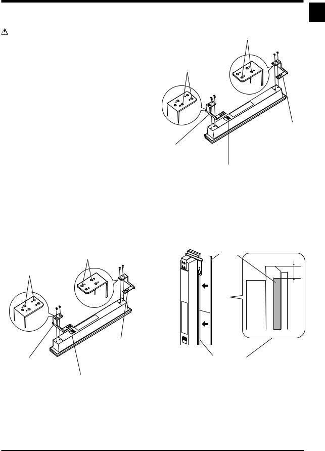
1 Attaching the Speaker Mounting |
|
(For RIGHT-TOP) |
|
Speaker Mounting Brackets |
(The skinny slot is |
||
Brackets to the Speakers |
used for mounting to |
||
(For RIGHT-BOTTOM) |
the top.) |
||
There is a left speaker and a right speaker. When you |
|||
Place the speaker so its terminals (bottom) |
|||
are mounting them, check the label on the back to get |
|||
them right. |
are facing you. (Example of right speaker) |
||
|
|
||
There are top and bottom speaker mounting brackets |
2 If mounting the speakers Flush, affix |
||
for both the left and the right speaker. Attach the |
the padding strip to the side of the |
||
appropriate bracket to the top and the bottom on the |
speakers (side that touches the |
||
back of the speakers with the enclosed screws. (See |
|||
display). |
|
||
Diagram) |
|
||
The diagram depicts the mounting of the right |
Use the enclosed padding strips to buffer the speakers |
||
speaker. The left speaker mounts in the same way. |
when mounting them Flush. Peel off the protective strip |
||
|
and affix to the side of the speakers. |
||
Air mounting
Screw Holes for Air mounting (2 on outside)
Screw Holes for Air mounting (2 on outside)
|
Speaker Mounting |
|
|
Brackets |
|
|
(For RIGHT-TOP) |
|
Speaker Mounting Brackets |
(The skinny slot is used |
|
for mounting to the top.) |
||
(For RIGHTBOTTOM) |
||
|
Padding Strip
(10) |
Where to position the padding strip
Place the speaker so its terminals (bottom) are facing you. (Example of right speaker)
English
3
English
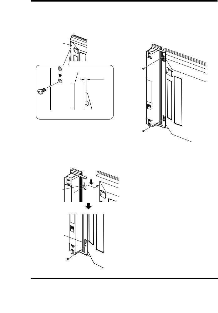
3Screw an enclosed screw into the speaker mounting hole (lower of the
two) at the top, back of the display.
Do not tighten it all the way yet. Leave it loose, with about 5 mm left to tighten.
Speaker Mounting Hole
Top, Back of
Display
Top of Display
5 mm
Leave a space of about 5 mm
4Hang the speaker mounting bracket on the screw you installed at the top by passing the wide part over it and lowering into the slot; screw in the
lower screw temporarily.
After passing the wide part of the hole of the speaker mounting bracket (top) over the screw, lower the speaker onto it.
After passing the wide part of the hole over the screw, lower the speaker.
Tighten the bottom speaker mounting bracket to the display temporarily (one place bottom).
5Adjust the position of the speaker and then fix the upper and lower screws firmly.
6Tighten the two screws, at the top and bottom for each speaker (total of four screws), thus fixing the speakers to the display.
4
English
CONNECTION TO A PLASMA DISPLAY
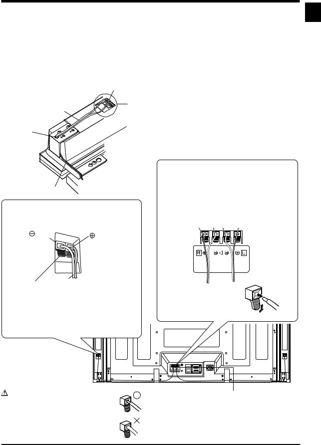
CONNECTING THE SPEAKERS
1 Pass the speaker cables through the hole in the speaker mounting bracket. 2 Connect the speaker cables to the speaker.
3 Press the speaker cables into the groove of the bracket. 4 Connect the speaker cables to the display.
Speaker Terminal
2
Speaker Cable
3
1
Groove
Connecting your Speaker Cables (to the speaker)
(black) |
(red) |
|

 Gray Line
Connecting your Speaker Cables (to the display)
Connect the cables correctly with respect to the polarity of the Plasma Display and the speaker terminals, that is, ª cable to ª terminals and · cable to · terminals. To do so, connect the cable with the gray line to the ª terminals and the white cable to the · terminals.
Gray Line White White Gray Line
White |
|
|
Push the lever, insert the end of the speaker cable |
÷ Press the lever and insert the |
|
into the hole, and release the lever. |
end of the cable. |
|
|
÷ When you release the lever, |
|
Pay attention to the polarity of the speaker terminals |
it clamps onto the speaker |
|
cable. |
||
when making connections. (The gray line represents |
||
|
||
the ª terminal) |
|
Warning |
4 |
|
If you insert the speaker cable too far so that |
||
|
||
the insulation is touching the speaker |
|
|
terminal, you may not get any sound. |
|
English
5
English
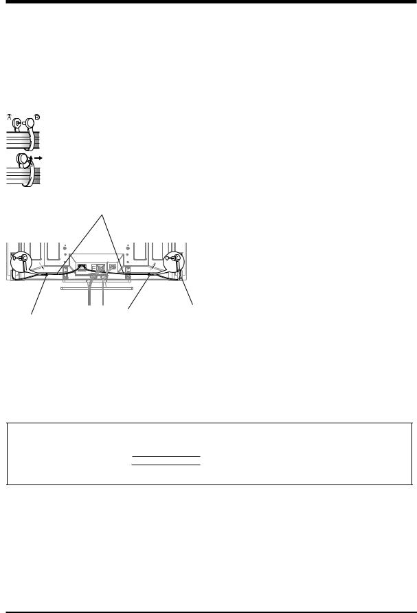
HOW TO ROURE CABLES
Speed clamps are included with the Plasma Display for tidying your cables and keeping extra cable length out of the way.
Attach speed clamps at the direction of the running cables.
*When the Pioneer stand, sold separately, is not used, use the two holes that are marked with arrows in the diagram (  ) as the holes for attaching speed clamps.
Using Speed Clamps
Wrap the speed clamp around the bundled cables and press B into hole A.
To remove a speed clamp, use pliers to twist it 90° and then pull it out. (This may result in weakening or damaging the clamp.)
Speaker Cable
∞ Rear of Display 
Speed Clamp
Speed
Speed Clamp Mounting Hole Clamp
Mounting Hole
CABINET MAINTENANCE
÷Use a polishing cloth or dry cloth to wipe off dust and dirt.
÷When the cabinet is very dirty, wipe with a soft cloth moistened with water-diluted cleanser; then wipe again with a dry cloth. Do not use furniture wax or cleaners. They may damage the surface of the cabinet.
÷Never use thinner, benzine, insecticide sprays and other chemicals on or near the cabinets, since these will corrode the surfaces.
÷When a chemical cloth is used, read the cautions for the chemical cloth carefully.
SPECIFICATIONS
Cabinet: Bass-reflex type
Used speakers (two-way system):
Woofer (for low tones) ................ |
4.8 × 13 cm cone type |
Tweeter (for high tones) |
........... 2.5 cm semidome type |
Nominal impedance ..................................................... |
8 Ω |
Frequency Range ..................................... |
64 to 30,000 Hz |
Sensitivity (1 w, 1 m) ................................................ |
81 dB |
Permissible input : |
|
Max. input .............................................................. |
13 W |
Rated input .............................................................. |
4 W |
Crossover frequency ................................................ |
3 kHz |
External Dimensions ...... |
76.5 (W) × 717 (H) × 92 (D) mm |
Weight ..................................................................... |
1.7 kg |
Accessory parts (for 2 speakers) |
|
............................................................ |
Speaker cable × 2 |
...................................................... |
Screw (M5 × 10) × 16 |
............................................................................. |
Bracket |
|
LEFT-TOP × 1 |
|
LEFT-BOTTOM × 1 |
|
RIGHT-TOP × 1 |
|
RIGHT-BOTTOM × 1 |
.............................................................. |
Padding strip × 2 |
.............................................. |
Operating Instructions × 1 |
NOTE:
Specifications and design subject to possible modification without notice, due to improvements.
IMPORTANT NOTICE – RECORD THE MODEL NUMBER AND SERIAL NUMBERS OF THIS EQUIPMENT BELOW. THE NUMBERS ARE ON THE REAR.
MODEL NO.
SERIAL NO.
KEEP THESE NUMBERS FOR FUTURE USE.
D1-4-2-6-2_En
Published by Pioneer Corporation. Copyright © 2005 Pioneer Corporation. All rights reserved.
6
 Loading...