


 TECHNICAL MANUAL (Ver.1.1A)
PLASMA DISPLAY : PDP-501MX/PDP-V501X
TABLE-TOP STAND: PDK-5001
SPEAKER SYSTEM: PDP-S02-LR
This manual provides precautions and information for installation, preparation, and handling of the plasma display and its dedicated mounting hardware.
Before installation and preparation work, choose a safe and appropriate site after thorough consideration of construction, materials used, strength, and surroundings. If the adequate safeguards are not in place, immediately halt the installation process and discontinue marketing activities.
CAUTION
 Exclamation marks placed within triangles are intended to alert users to the presence of important safety information. Be sure to read instructions indicated by this symbol.
PRECAUTIONS
•We accept no responsibility for losses resulting from the use of parts other than those supplied by us.
•We guarantee the performance of our products only when they are assembled and adjusted as described in this manual.
•The specifications and external designs shown in this manual are subject to change without notice.
About Mounting/Installation
•The product is sold under the assumption that installation will be performed by experienced, qualified experts. Refer all mounting and installation work to qualified personnel, or consult the nearest PIONEER dealer for assistance.
•We accept no responsibility for accident or loss resulting from failure to select an appropriate installation site, or for those occurring during assembly, installation, mounting, or operation of this product, or resulting from modifications made to the product, or from natural calamities.
1

Table of Contents |
|
|
|
FEATURES ................................................................................................................................................. |
|
4 |
|
SPECIFICATIONS |
|
|
|
2.1 |
Specifications ..................................................................................................................................................... |
|
6 |
2.2 |
External dimensions ......................................................................................................................................... |
|
10 |
2.3 |
Controls and connectors .................................................................................................................................. |
|
12 |
2.4 |
Remote control unit .......................................................................................................................................... |
|
14 |
INSTALLATION |
|
|
|
3.1 |
Installation site requirements ........................................................................................................................... |
|
16 |
3.2 |
Installation Conditions ...................................................................................................................................... |
|
18 |
|
3.2.1 Heat dissipation ....................................................................................................................................... |
|
18 |
|
3.2.2 Calculating heat quantity .......................................................................................................................... |
|
19 |
|
3.2.3 Product mounting holes ........................................................................................................................... |
|
19 |
|
3.2.4 Mount surface warping ............................................................................................................................ |
|
21 |
3.3 |
Installation Procedures ..................................................................................................................................... |
|
22 |
|
3.3.1 Transportation precautions ...................................................................................................................... |
|
22 |
|
3.3.2 Unpacking ................................................................................................................................................ |
|
22 |
|
3.3.3 Temporary installation using packing materials ....................................................................................... |
|
23 |
|
3.3.4 Re-packing ............................................................................................................................................... |
|
23 |
|
3.3.5 Wiring ...................................................................................................................................................... |
|
24 |
3.4 |
Special Installation ............................................................................................................................................ |
|
26 |
|
3.4.1 Mounting to fittings ................................................................................................................................. |
|
26 |
|
3.4.2 Hanging on the wall ................................................................................................................................. |
|
28 |
|
3.4.3 Embedding in the wall ............................................................................................................................. |
|
30 |
|
3.4.4 Ceiling suspension (with wires) ............................................................................................................... |
|
34 |
HOW TO USE THE STANDARD MOUNT EQUIPMENT |
|
|
|
4.1 |
Standard mount equipment features and characteristics ................................................................................. |
|
36 |
4.2 |
Handling the standard mount equipment ......................................................................................................... |
|
37 |
|
4.2.1 Handling precautions ............................................................................................................................... |
|
37 |
|
4.2.2 Precautions for installation contractors .................................................................................................... |
|
37 |
4.3 |
Table-top Stand: PDK-5001 ................................................................................. |
............................................. |
38 |
|
4.3.1 Specifications .............................................................................................. |
............................................. |
38 |
|
4.3.2 Assembling the stand .............................................................................................................................. |
|
39 |
|
4.3.3 Mounting to the main unit ....................................................................................................................... |
|
40 |
4.4 |
Plasma Display Ceiling Suspension Hardware (one-sided type): PDK-5002 |
NOT AVALABLE IN USA |
42 |
|
4.4.1 Specifications ........................................................................................................................................... |
|
42 |
|
4.4.2 Assembling and installing the mounting hardware and mounting the plasma display ............................ |
44 |
|
4.5 |
Tiltable Plasma Display Wall-Mount Hardware: PDK-5006 |
NOT AVALABLE IN USA |
48 |
|
4.5.1 Specifications ........................................................................................................................................... |
|
48 |
|
4.5.2 Assembling the mounting hardware and mounting the plasma display .................................................. |
|
50 |
4.6 |
Speaker System: PDP-S02-LR .......................................................................................................................... |
|
54 |
|
4.6.1 Specifications ........................................................................................................................................... |
|
54 |
|
4.6.2 Mounting to the main unit ....................................................................................................................... |
|
55 |
|
4.6.3 Mounting with the plasma ceiling-suspension hardware (PDK-5002) ..................................................... |
|
56 |
|
4.6.4 Mounting with PDK-5006 (wall-mounting hardware) ............................................................................... |
|
58 |
ADJUSTMENTS |
|
|
|
5.1 |
Before Beginning Adjustments ........................................................................................................................ |
|
60 |
|
5.1.1 Operating mode ....................................................................................................................................... |
|
60 |
|
5.1.2 Combination use of remote, unit operation panel, and PC ...................................................................... |
|
61 |
|
5.1.3 List of supported input signals ................................................................................................................. |
|
62 |
|
5.1.4 List of adjustable and settable items ....................................................................................................... |
|
65 |
|
5.1.5 Last memory ............................................................................................................................................ |
|
69 |
|
5.1.6 Aging ........................................................................................................................................................ |
|
69 |
5.2 |
Normal Operating Mode ................................................................................................................................... |
|
70 |
|
5.2.1 About the normal operating mode ........................................................................................................... |
|
70 |
5.3 Menu Mode ...................................................................................................................................................... |
|
71 |
|
|
5.3.1 About menu mode ................................................................................................................................... |
|
71 |
|
5.3.2 Example of menu mode operation .......................................................................................................... |
|
72 |
2

|
|
Table of Contents |
5.3.3 Settings in Menu Mode ........................................................................................................................... |
74 |
|
1) |
Setting the three-dimensional Y/C separator ....................................................................................... |
74 |
2) |
ABL On/Off .......................................................................................................................................... |
74 |
3) MP mode On/Off ................................................................................................................................. |
74 |
|
4) |
Auto power off..................................................................................................................................... |
76 |
5) |
Setting up peripheral equipment ......................................................................................................... |
77 |
6) |
Setting the input signal format ............................................................................................................ |
78 |
7) |
Setting the clamp position ................................................................................................................... |
79 |
8) |
Setting the color system...................................................................................................................... |
81 |
5.3.4 Menu Layers ............................................................................................................................................ |
82 |
|
1) |
Adjustments at Menu Layers-1 of 2 .................................................................................................... |
82 |
2) |
Adjustments at Menu Layers-2 of 2 .................................................................................................... |
83 |
5.4 Integrator Mode ............................................................................................................................................... |
85 |
|
5.4.1 About the integrator mode ...................................................................................................................... |
85 |
|
5.4.2 Example of integrator mode operation .................................................................................................... |
86 |
|
5.4.3 Adjustments and settings in the integrator mode ................................................................................... |
88 |
|
1) |
Adjusting the PICTURE parameters..................................................................................................... |
88 |
2) |
Adjusting the WHITE BALANCE parameters ....................................................................................... |
89 |
3) |
Adjusting the SCREEN parameters ..................................................................................................... |
90 |
4) |
Setting the color mode ........................................................................................................................ |
91 |
5) |
Setting the baud rate ........................................................................................................................... |
92 |
6) |
Mirror mode ......................................................................................................................................... |
93 |
7) |
Setting STD-RGB ................................................................................................................................. |
94 |
8) |
Adjusting the side mask ...................................................................................................................... |
95 |
9) |
Initializing adjustments (TOTAL INITIALIZE) ........................................................................................ |
96 |
5.4.4 Integrator mode menu layers .................................................................................................................. |
97 |
|
5.4.5 PICTURE and WHITE BALANCE parameter memory area table ............................................................. |
98 |
|
5.4.6 SCREEN parameter memory area table ................................................................................................ |
100 |
|
5.5 RS-232C Adjustment Mode ........................................................................................................................... |
103 |
|
5.5.1 About the RS-232C adjustment mode ................................................................................................... |
103 |
|
5.5.2 Interface ................................................................................................................................................. |
104 |
|
5.5.3 List of RC-232C commands ................................................................................................................... |
105 |
|
5.5.4 About the GET commands .................................................................................................................... |
107 |
|
5.6 Combination Connection ................................................................................................................................ |
108 |
|
5.6.1 Connections ........................................................................................................................................... |
108 |
|
5.6.2 Assigning IDs ......................................................................................................................................... |
110 |
|
5.7 KEY LOCK/UNLOCK ....................................................................................................................................... |
113 |
|
5.7.1 Functions ............................................................................................................................................... |
113 |
|
5.7.2 How to switch KEY LOCK/UNLOCK ...................................................................................................... |
113 |
|
OPERATING PRECAUTIONS AND RECOMMENDATIONS ................................................................ |
114 |
|
6.1 About pseudo-contour .................................................................................................................................... |
114 |
|
6.2 Cautions ......................................................................................................................................................... |
114 |
|
Maintenance and Cleaning................................................................................................................... |
115 |
|
CAUTION
•To prevent injury and material damage, thoroughly read this manual and all labels found on equipment before attempting to mount, install, move, or adjust the product.
•Do not install the unit outside or in open air. Doing so will lead to water seepage into the system, resulting in fire or electric shock.
•Be especially careful when working around parts of the system that have sharp edges.
•When performing installation work from a height, take suitable precautions to guard against falling. Set up a barrier around the work site to prevent accidentally-dropped objects from injuring persons standing or walking below.
•Keep all foreign objects out of the unit. Do not tamper with the unit, or fire or electric shock may result.
•Observe the following operating environmental limitations:
Temperature: 0 to 40°C
Humidity: 20 to 80%
• Install the unit only in properly ventilated areas.
3

Features
Features and Functions of the PDP-501MX Plasma Display
• High-definition XGA wide panel
The Display uses a high-definition XGA wide panel, which provides 1280 x 768 resolution with more than 980.000 pixels. This resolution is more than 2.5 times higher than that of conventional panels, and enables multimedia information to be reproduced more vividly and accurately than ever before.
• Clear, high-quality image
Provides 8-bit RGB in 256 gradations/16.77 million colors. A new exclusive technology developed by Pioneer eliminates the pseudo-contour anomaly, that is typically observed in plasma displays.
• Unrivalled brightness
A brightness of 350 cd/m2 (white peak, for panel unit), which is the highest so far for XGA panels, has been achieved by maximizing light-emitting efficiency.
• Flat, lightweight design
The Pioneer plasma display monitor is also unrivalled in compactness: the 50-inch screen is only 98 mm in depth, and weighs only 43.0 kg. It can therefore be mounted at locations where conventional displays are difficult to install.
• Supports a variety of signals from computers
Full specification PC are supported in video modes from VGA (640 x 480 resolution) to XGA (1024 x 762 resolution). The SXGA (1280 x 1024 resolution) mode also accommodates PC signals, although a summary replay approach is employed in this mode. The use of a dedicated video card also allowed access to a display of 1280 x 768 resolution, as well. This monitor also supports HDTV broadcasts*.
Note:
* To display HDTV images on this monitor, an HDTV decoder, additionally.
•Optimized for industrial/public-address use
•An RS-232C interface is provided for control from the exterior
•The combination terminal enables a single PC to control multiple monitor systems
•The integrator mode enables more precise adjustments than ever before
•A color temperature (white balance) switching function is provided for retakes, and a key-lock feature prevents accidental or unauthorized use of the monitor
•Multiple input and output terminals (four inputs and eight outputs) are provided
4

Features
5

Specifications
2.1 Specifications (U.S. Model and Taiwanese Model)
Light-emitting panel: |
...... 50-inch plasma display panel |
|
Aspect ratio: ........................................................... |
|
16:9 |
PEL: ................................. |
|
1280 x 768 (XGA supported) |
PEL pitch: ................ |
0.858 (H·RGB trio) x 0.808 (V) mm |
|
Gradation: ........................ |
|
256/16.77 million full colours |
Intensity: .......... |
350 cd/m2 (white peak, separate panel) |
|
Viewing angle:....... |
Horizontal: more than 160 degrees |
|
|
|
Vertical: more than 160 degrees |
Input/output |
|
|
INPUT 1
Connector type: see NOTE 1 and NOTE 2 RCA jack
(composite video signal, 1 Vp-p/75Ω input) BNC terminal
(composite video signal, 1 Vp-p/75Ω input) Mini-Din, 4-pin/S terminal
(S2 video signal, Y: 1Vp-p; C: 0.286 Vp-p/75Ω input) Output (BNC, under 75Ω output): Yes (see NOTE 3 and NOTE 4)
INPUT 2
Connector type:
RCA jack x 3
(Y: 1 Vp-p; color difference: 0.7 Vp-p/ 75Ω input)
INPUT 3
Connector type:
BNC terminal x 5
(GRB: video section 0.7 Vp-p; sync section 0.3 Vp- p/75Ω input) (HD/CS; VD: TTL level/ 75Ω and 2.2 kΩ inputs switchable)
INPUT 4
Connector type:
Mini D-sub, 15-pin (GBR: video section 0.7 Vp-p; sync section 0.3 Vp-p/75Ω input) (HD/CS; VD: TTL level/2.2 kΩ input)
Output (Mini D-sub, 15-pin; 75Ω output: Yes (see NOTE 4)
* Microsoft Plug & Play (VESA DDC 1/2B) supported
Control Terminal
RS-232C (for control using a PC)
Connector type: D-sub, 9-pin
Baud rate: 1200, 2400, 4800, 9600, 19200 bps (NOTE 5)
Combination In/Out Terminal
For simultaneous control of multiple units Connector type: Mini-Din, 6-pin (NOTE 6)
Power requirements: |
.... AC 120 V, 60 Hz (U.S. Model) |
||
AC 110 V, 60 Hz (Taiwanese Model) |
|||
In-rush: ..................................................... |
|
|
less than 25A |
Power factor: ........................................ |
|
|
more than 0.95 |
Consumption: .......... |
555 W (NOTE 7) (3 W in standby) |
||
External dimensions (WxHxD): |
... |
1218 x 714 x 98 mm |
|
(47-31/32(W) x 28-1/8(H) x 3-7/8(D) inch) |
|||
Weight: ............................................................... |
|
|
43.0 kg |
|
|
|
(94 lbs. 130z.) |
Operating temperature:................. |
|
0 to 40°C (NOTE 8) |
|
|
|
|
(32 to 104°F) |
Operating humidity:..................................... |
|
|
20 to 80% |
Operating atmospheric pressure: |
......... 0.9 to 1.1 atm |
||
Storage limitations |
|
|
|
Temperature: ........................................ |
|
|
–10 to +45°C |
|
|
|
(14to 113°F) |
Humidity: ................................................... |
|
|
20 to 80% |
Atmospheric pressure: ........................ |
|
0.6 to 1.5 atm |
|
Stacking: ................................. |
|
Fewer than three tiers |
|
Standard Accessories |
|
|
|
Power cord ............................................................ |
|
|
x 1 |
AC adapter plug (3p to 2p) |
|
|
|
................................... |
x 1 (Taiwanese Model only) |
||
RCA/BNC conversion adaptor |
|
|
|
................................... |
x 1 (Taiwanese Model only) |
||
Remote control unit |
............................................... |
|
x 1 |
AA battery .............................................................. |
|
|
x 2 |
Wipe cloth ............................................................. |
|
|
x 1 |
Speed clamp .......................................................... |
|
|
x 2 |
Bead band .............................................................. |
|
|
x 2 |
Operation manual .................................................. |
|
|
x 1 |
Warranty card ........................................................ |
|
|
x 1 |
6

Specifications
NOTE 1 To prevent malfunctions and breakdowns, avoid connecting the RCA jack and BNC terminal simultaneously, since they are electrically connected to each other inside the body.
NOTE 2 If the RCA jack or the BNC terminal is connected at the same time as the S terminal, signals received at the S terminal receive priority.
NOTE 3 Signals received at the RCA jack or BNC terminal are sent from this terminal. Signals received at the S terminal are not.
NOTE 4 No signal is sent in power-off or standby status.
NOTE 5 Defaults to 4800 bps. This setting can be changed from the remote or from a PC.
NOTE 6 Connection cables are optional and are not supplied as standard equipment. Use commercially-available Mini-Din 6-pin cables (straight).
NOTE 7 Allow for 600 VA of consumption per unit.
NOTE 8 The correct operating environmental temperature may vary, depending on the installation site. (Refer to Section 3: Installation.)
VESA is a registered trademark of the Video Electronics Standards Association.
Specifications and external designs are subject to change without notice.
Signals supported by INPUT 1
Vertical |
Horizontal |
Signal |
|
||
Frequency |
Frequency |
Remarks |
|||
Format |
|||||
Fv (Hz) |
Fh (kHz) |
|
|||
|
|
|
|||
60 |
15.7 |
Composite |
NTSC |
||
|
|
||||
S video signal |
|||||
|
|
|
|||
|
|
|
|
|
|
Signals supported by INPUT 2 |
|
||||
|
|
|
|
|
|
Vertical |
Horizontal |
Signal |
|
|
|
Frequency |
Frequency |
|
Remarks |
||
Format |
|
||||
Fv (Hz) |
Fh (kHz) |
|
|
||
|
|
|
|||
60 |
15.7 |
Component |
|
|
|
|
|
|
|
||
|
31.5 |
Component |
|
|
|
Signals supported by INPUT 3/4 (video) —1 of 2
Vertical |
Horizontal |
Signal |
|
|
|
Frequency |
Frequency |
Remarks |
|||
Format |
|||||
Fv (Hz) |
Fh (kHz) |
|
|
||
|
|
|
|||
60 |
15.7 |
RGB (Note 9) |
SDTV 480i |
|
|
|
|
Component |
|
|
|
|
|
|
|
||
|
31.5 |
RGB |
SDTV 480p |
||
|
|
|
|
|
|
|
|
Component |
|
|
|
|
|
|
|
||
|
33.8 |
RGB |
HDTV 1080i |
||
|
|
Component |
|
|
|
|
|
|
|
||
|
45.0 |
RGB |
HDTV 720p |
||
|
|
Component |
|
|
|
Signals supported by INPUT 3/4 (PC signals) —2 of 2
Model |
|
Vertical |
Horizontal |
|
Dot x line |
Frequency |
Frequency |
||
Name |
||||
|
Fv (Hz) |
Fh (kHz) |
||
|
|
|||
PC/AT |
640 x 400 |
70.1 |
31.5 |
|
compatibles |
|
|
|
|
640 x 480 |
59.9 |
31.5 |
||
|
|
|
|
|
|
|
72.8 |
37.9 |
|
|
|
|
|
|
|
|
75 |
37.5 |
|
|
|
|
|
|
|
800 x 600 |
56.3 |
35.2 |
|
|
|
|
|
|
|
|
60.3 |
37.9 |
|
|
|
|
|
|
|
|
72.2 |
48.1 |
|
|
|
|
|
|
|
|
75 |
46.9 |
|
|
|
|
|
|
|
1024 x 768 |
60 |
48.4 |
|
|
|
|
|
|
|
|
70.1 |
56.5 |
|
|
|
|
|
|
|
|
75 |
60 |
|
|
|
|
|
|
|
|
87(Note 11) |
35.5(Note 10) |
|
|
|
|
|
|
|
1280 x 1024 |
60 |
64(Note 10) |
|
|
|
|
|
|
Macintosh |
640 x 480 |
66.7 |
35 |
|
|
|
|
|
|
|
832 x 624 |
74.6 |
49.7 |
|
|
|
|
|
|
|
1024 x 768 |
74.9 |
60.2 |
|
|
|
|
|
|
|
1152 x 870 |
75.1 |
68.7(Note 10) |
|
|
|
|
|
|
NEC |
640 x 400 |
56.4 |
24.8 |
|
PC-9800 |
|
|
|
|
|
70.1 |
31.5 |
||
|
|
|
|
|
|
640 x 480 |
59.9 |
31.5 |
|
|
|
|
|
|
|
|
75 |
37.5 |
|
|
|
|
|
|
|
800 x 600 |
60.3 |
37.9 |
|
|
|
|
|
|
|
|
75 |
46.9 |
|
|
|
|
|
|
|
1024 x 768 |
70.1 |
56.5 |
|
|
|
75 |
60 |
|
|
1280 x 1024 |
60 |
64(Note 10) |
NOTE 9 Can be reproduced depending on settings in integrator mode, but primary quality images are not available.
NOTE 10 Simplified reproduction.
NOTE 11 Interlaced signal (frame frequency of 43.5 Hz)
NEC is a trademark of NEC Corp.
PC-9800® is a registered trademark of NEC Corp.
Macintosh® is a registered trademark of Apple Computer, Inc.
7

Specifications
2.1 Specifications (EURO Model)
Light-emitting panel: |
...... 50-inch plasma display panel |
|
Aspect ratio: ........................................................... |
|
16:9 |
PEL: ................................. |
|
1280 x 768 (XGA supported) |
PEL pitch: ............... |
0.858 (H)(RGB trio) x 0.808 (V) mm |
|
Gradation: ........................ |
|
256/16.77 million full colours |
Intensity: .......... |
350 cd/m2 (white peak, separate panel) |
|
Viewing angle:............ |
|
Horizontal 160 degrees or more |
|
|
Vertical: 160 degrees or more |
Inputs/outputs
INPUT 1
Connector type: NOTE 1 and NOTE 2 RCA jack
(composite video signal, 1 Vp-p/75Ω input) BNC terminal
(composite video signal, 1 Vp-p/75Ω input) Mini-Din, 4-pin/S terminal
(S2 video signal, Y: 1Vp-p; C:0.286 Vp-p/75Ω input) Output (BNC, 75Ω output): Yes (see NOTE 3 and NOTE 4)
INPUT 2
Connector type
RCA jack x 3
(Y: 1 Vp-p; color difference: 0.7 Vp-p/ 75Ω input)
INPUT 3
Connector type:
BNC terminal x 5 (GBR:video section 0.7 Vp-p; sync section 0.3 Vp-p/75Ω input) (HD/CS; VD: TTL level/ 75Ω and 2.2 kΩ inputs, switchable)
Control Terminal
RS-232C (for control using a PC)
Connector type: D-sub, 9-pin
Baud rate: 1200, 2400, 4800, 9600, 19200 bps (NOTE 5)
Combination Input/Output Terminal
Used for simultaneous control of multiple units Connector type: Mini-Din, 6-pin (NOTE 6)
Power requirements: ............. |
AC 100-240 V, 50/60 Hz |
|
Electric current: .......................... |
5.6 to 2.3 A (NOTE 7) |
|
In-rush: .................................................... |
|
less than 25 A |
Power factor: ........................................ |
|
more than 0.95 |
External dimensions (WxHxD): ... |
1218 x 714 x 98 mm |
|
(47-31/32(W) x 28-1/8(H) x 3-7/8(D) inch) |
||
Weight: ............................................................... |
|
43.0 kg |
|
|
(94 lbs. 130z.) |
Operating temperature:................. |
|
0 to 40°C (NOTE 8) |
|
|
(32 to 104°F) |
Operating humidity:..................................... |
|
20 to 80% |
Operating atmospheric pressure: |
......... 0.9 to 1.1 atm |
|
Storage limitations |
|
|
Temperature: ........................................ |
|
–10 to +45°C |
|
|
(14 to 113°F) |
Humidity: ................................................... |
|
20 to 80% |
Atmospheric pressure: ........................ |
|
0.6 to 1.5 atm |
Stacking: ................................. |
Fewer than three tiers |
|
Standard accessories
INPUT 4
Connector type:
Mini D-sub, 15-pin (GBR: video section 0.7 Vp-p; sync section 0.3 Vp-p/75Ω input) (HD/CS; VD: TTL level/2.2 kΩ input)
Output (Mini D-sub, 15-pin; 75Ω input: Yes (NOTE 4) * Microsoft Plug & Play (VESA DDC 1/2B) supported
Power cord ............................................................ |
x 1 |
RCA/BNC conversion adaptor ................................ |
x 3 |
Remote control unit ............................................... |
x 1 |
AA battery.............................................................. |
x 2 |
Wipe cloth ............................................................. |
x 1 |
Speed clamp .......................................................... |
x 2 |
Bead band.............................................................. |
x 2 |
Operation manual .................................................. |
x 1 |
Warranty card ........................................................ |
x 1 |
8

Specifications
NOTE 1 To prevent malfunctions and breakdowns, avoid connecting the RCA jack and BNC terminal simultaneously, since they are electrically connected to each other inside the body.
NOTE 2 If the RCA jack or the BNC terminal is connected at the same time as the S terminal, signals received at the S terminal receive priority.
NOTE 3 Signals received at the RCA jack or BNC terminal are sent from this terminal. Signals received at the S terminal are not.
NOTE 4 No signal is sent in power-off or standby status.
NOTE 5 Defaults to 4800 bps. This setting can be changed from the remote or from a PC.
NOTE 6 Connection cables are optional and are not supplied as standard equipment. Use commercially available Mini-Din 6-pin cables (straight).
NOTE 7 Allow for 600 VA of consumption per unit.
NOTE 8 The correct operating environmental temperature may vary, depending on the installation site. (Refer to Section 3: Installation.)
VESA is a registered trademark of the Video Electronics Standards Association.
Specifications and external designs are subject to change without notice.
Signals supported by INPUT 1
Vertical |
Horizontal |
Signal |
|
|||
Frequency |
Frequency |
Remarks |
||||
Format |
||||||
Fv (Hz) |
Fh (kHz) |
|
||||
|
|
|
||||
50 |
15.6 |
|
Composite |
PAL, SECAM |
||
|
|
|
|
|
||
|
|
|
S video signal |
|||
|
|
|
|
|||
|
|
|
|
|
|
|
60 |
15.7 |
|
Composite |
NTSC |
||
|
|
|
||||
|
|
|
|
|
4.43 NTSC |
|
|
|
|
S video signal |
|||
|
|
|
|
|||
|
|
|
|
|
|
|
Signals supported by INPUT 2 |
|
|||||
|
|
|
|
|
|
|
Vertical |
Horizontal |
Signal |
|
|
||
Frequency |
Frequency |
|
Remarks |
|||
Format |
|
|||||
Fv (Hz) |
Fh (kHz) |
|
|
|||
|
|
|
||||
50 |
15.6 |
|
Component |
|
|
|
|
|
|
|
|
|
|
|
31.3 |
|
Component |
|
|
|
|
|
|
|
|
|
|
60 |
15.7 |
|
Component |
|
|
|
|
|
|
|
|
|
|
|
31.5 |
|
Component |
|
|
|
|
|
|
|
|
|
|
Signals supported by INPUT 3/4 (video) —1 of 2
Vertical |
Horizontal |
Signal |
|
||
Frequency |
Frequency |
Remarks |
|||
Format |
|||||
Fv (Hz) |
Fh (kHz) |
|
|||
|
|
||||
50 |
15.6 |
|
RGB (Note 9) |
|
|
|
|
|
Component |
|
|
|
31.3 |
|
RGB |
|
|
|
|
|
Component |
|
|
60 |
15.7 |
|
RGB |
|
|
|
|
|
Component |
|
|
|
31.5 |
|
RGB |
|
|
|
|
|
Component |
|
|
|
33.8 |
|
RGB |
|
|
|
|
|
Component |
|
|
|
45.0 |
|
RGB |
|
|
|
|
|
Component |
|
|
Signals supported by INPUT 3/4 (PC signals)—2 of 2
Model |
|
Vertical |
Horizontal |
||
Dot x line |
Frequency |
Frequency |
|||
Name |
|||||
|
Fv (Hz) |
Fh (kHz) |
|||
|
|
||||
|
|
|
|
|
|
PC/AT |
640 x 400 |
70.1 |
31.5 |
|
|
compatibles |
640 x 480 |
59.9 |
31.5 |
|
|
|
|
72.8 |
37.9 |
|
|
|
|
75 |
37.5 |
|
|
|
800 x 600 |
56.3 |
35.2 |
|
|
|
|
60.3 |
37.9 |
|
|
|
|
72.2 |
48.1 |
|
|
|
|
75 |
46.9 |
|
|
|
1024 x 768 |
60 |
48.4 |
|
|
|
|
70.1 |
56.5 |
|
|
|
|
75 |
60 |
|
|
|
|
87(Note 11) |
35.5(Note 10) |
||
|
1280 x 1024 |
60 |
64(Note 10) |
||
Macintosh |
640 x 480 |
66.7 |
35 |
|
|
|
832 x 624 |
74.6 |
49.7 |
|
|
|
1024 x 768 |
74.9 |
60.2 |
|
|
|
1152 x 870 |
75.1 |
68.7(Note 10) |
||
NEC |
640 x 400 |
56.4 |
24.8 |
|
|
PC-9800 |
|
70.1 |
31.5 |
|
|
|
640 x 480 |
59.9 |
31.5 |
|
|
|
|
75 |
37.5 |
|
|
|
800 x 600 |
60.3 |
37.9 |
|
|
|
|
75 |
46.9 |
|
|
|
1024 x 768 |
70.1 |
56.5 |
|
|
|
|
75 |
60 |
|
|
|
1280 x 1024 |
60 |
64(Note 10) |
|
|
|
|
|
|
|
|
NOTE 9 Can be reproduced depending on settings in integrator mode, but primary quality images are not available.
NOTE 10 Simplified reproduction.
NOTE 11 Interlaced signal (frame frequency of 43.5 Hz)
NEC is a trademark of NEC Corp.
PC-9800® is a registered trademark of NEC Corp. Macintosh® is a registered trademark of Apple Computer, Inc.
9
External Dimensions
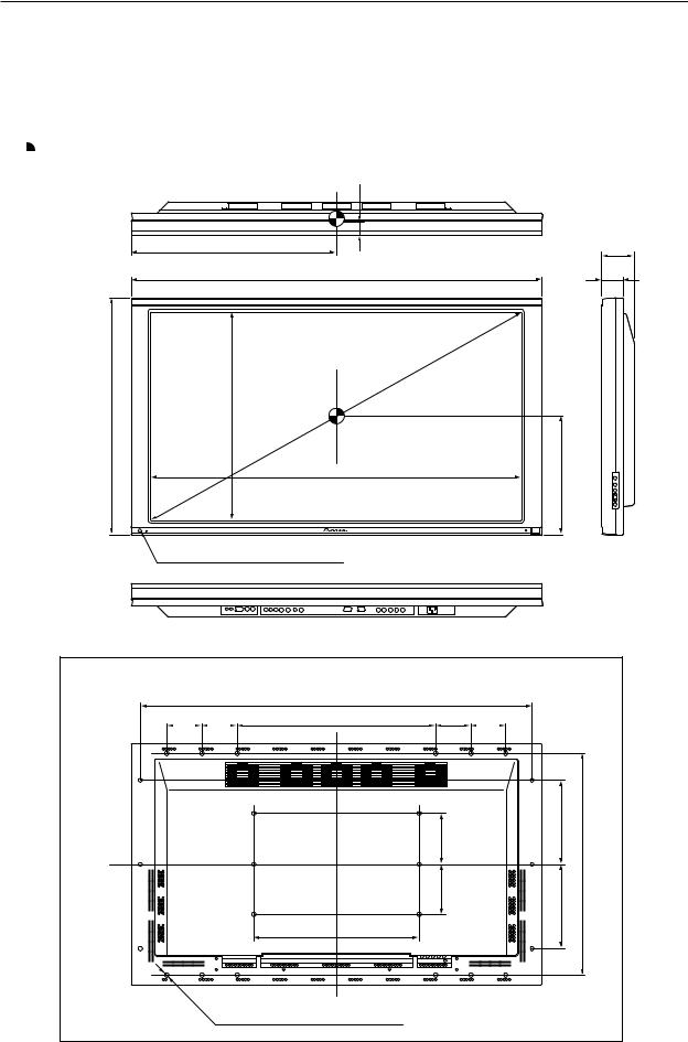
2.2 External Dimensions
Weight: 43.0 kg
Material: Front: Resin; Rear: Resin
Treatment: Front: Laser-satin gray paint; Rear: Laser-satin gray paint
For packaging information, refer to 3.3.2 Unpacking
 : Center of gravity
(Unit: mm)
31
609 |
98.5 |
1218 |
65.5 |
714 |
628 |
1108
Light sensor for the remote
357
Rear View
|
|
1162 |
|
|
104 |
104 |
590 |
104 |
104 |
150 |
250 |
150 |
660 |
250 |
496
24-M8 (ø16 mm, with hole rivet)
10
External Dimensions
< Main Switch > |
< Main Unit Operation Panel > |
< Light Sensor for the Remote >
11
Controls and Connectors
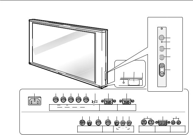
2.3 Controls and Connectors
< Operation Panel >
STANDBY /ON
3
8
|
|
INPUT |
|
|
4 |
|
|
MENU |
|
|
5 |
|
|
ADJUST |
1 |
2 |
6 |
SET
 7
7
POWER
9 |
0 |
- |
= |
~ |
! |
@ |
# |
$ |
< Connectors > |
|
|
|
|
|
|
|
|
|
|
||
|
|
|
|
|
|
|
|
|
(at the rear of the main unit) |
|
|
Y |
CB/PB |
CR/PR |
|
|
75Ω 2.2kΩ |
INPUT 4 |
OUTPUT |
|
|
|
G |
B |
R |
HD |
VD |
|
|
|
||
|
|
|
(INPUT 4) |
|
|
|||||
|
(ON SYNC) |
INPUT 3 |
(H/V SYNC) |
|
|
|
|
|||
|
|
|
|
|
|
|||||
|
|
|
|
|
% ^ & * ( ) _ |
+ |
¡ ™ |
|||
|
|
|
|
S - VIDEO |
VIDEO |
OUTPUT |
Y CB/PB CR/PR |
IN OUT |
IN OUT Î |
|
|
|
|
|
|
INPUT 1 |
(INPUT 1) |
C. VIDEO |
|
RS - 232C |
|
|
|
|
|
|
INPUT 2 |
CONBINATION |
CONTROL |
|||
|
|
|
|
|
|
|
|
|||
< Main Power Switch Section >
1STANDBY/ON indicator
Red indicates standby status, green indicates powering
on.
2POWER switch
Turns main power on or off.
< Control Panel >
3Power switch
Toggles unit on or off (standby).
4INPUT switch
Used to select inputs
5MENU switch
Switches the menu screen on or off.
6ADJUST buttons
Used to move the cursor on the menu screen or to
increment/decrement adjustment values
7 SET button
Used to select an adjustment item in the menu screen or to change settings
8KEY LOCK/UNLOCK button (hidden)
Renders the operation panel and remote operative or inoperative.
< Connectors >
9 AC INLET
INPUT 3 Inputs
These RGB inputs are composed of five BNC terminals,
0to !. They also support the component video signal (settings required in the menu screen).
0Green Input: 75Ω
Receives signals of G, G with sync, and Y.
- Blue Input: 75Ω
Receives signals of B, CB, and PB.
= Red Input: 75Ω
Receives signals of R, CR, and PR.
~ Horizontal and Composite Sync Signal Input: 75Ω/ 2.2kΩ
Receives signals of HD, and H/V Sync.
!Vertical Sync Signal Input: 75Ω/2.2 kΩ
Receives a VD signal.
@Sync Signal Input Impedance switch
Used to switch input impedance for items ~ and ! between 75Ω and 2.2 kΩ.
12

Controls and Connectors
INPUT 4 Input
#INPUT 4 input terminal
Mini D-Sub 15-pin terminal for connection of RGB signals
This terminal also supports component signals (settings required in the menu screen).
This terminal supports Microsoft Plug & Play (VESA DDC 1/2B).
(VESA is a registered trademark of the Video Electronics Standards Association.)
INPUT 4 Output
$INPUT 4 output terminal
Signals fed to the INPUT 4 input terminal # are sent from this output terminal. No signal is sent when power is switched off, or in standby status.
NOTE: When the unit is connected in a series using this output terminal, up to five units can be connected including the unit to which signals are first input. If you use separate sync or composite sync signal, over 4.8 Vp-p sync level
is necessary between the video source and the first unit, under the condition of 2.2 kΩ input
impedance.
INPUT 1 Inputs
% S2 Video Input terminal (S terminal)
^ Video Input terminal (RCA jack)
&Video Input terminal (BNC terminal)
To prevent malfunctions and breakdowns, avoid connecting the RCA jack and BNC terminal simultaneously, since they are electrically connected to each other inside the body.
INPUT 1 Output
*Video Output terminal
Signals fed to the INPUT 1 Video Input ^ or & are sent from this output terminal. This terminal does not carry signals received at the S-input terminal %. No signal is available at this output terminal when power is switched off, or in standby status.
NOTE: When the unit is connected in a series using this output terminal, up to five units can be connected including the unit to which signals are first input.
INPUT 2 Input
Component video input terminals composed of three RCA jacks ( to _.
( Y Input: 75Ω
) CB and PB Input: 75Ω
_ CR and PR Input: 75Ω
Control
+Combination Input and Output terminals
Used for simultaneous control of multiple units (Refer to 5.6 Combination Connections)
NOTE: No ABL linkage function is provided. These terminals are incompatible with multi-
projections such as the RM-V4800V.
¡ Control connector (conforming to RS-232C)
Used to make adjustments or settings externally
™SR IN/OUT terminals
For SR connection (refer to the operation manual) to AV units from Pioneer
NOTE: This product does not support RU-V107 wired remote control units.
13
Remote Control Unit
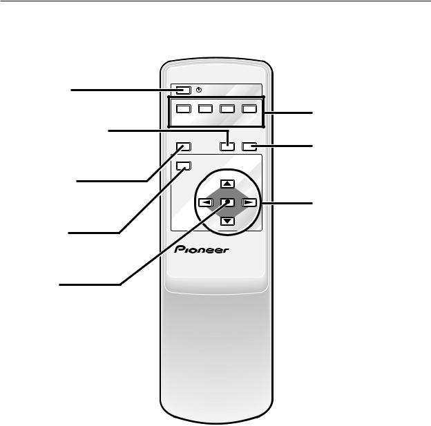
2.4 Remote Control Unit
Power switch |
|
STANDBY/ON |
|
|
|
|
|
|
|
||
Used to turn the system on or off |
INPUT1 |
INPUT2 |
INPUT3 |
INPUT4 |
|
(standby) |
VIDEO |
C.VIDEO |
RGB |
RGB |
Input switches |
|
|||||
|
S-VIDEO |
( RCA ) |
( BNC ) |
( D-sub ) |
Used to select inputs |
Full Auto-Zoom button |
|
|
|
|
|
|
FULL AUTO SCREEN |
|
|||
Used to turn full auto-zoom on or off |
|
|
|||
DISPLAY |
|
ZOOM |
SIZE |
Screen Size switch |
|
|
|
|
|
||
|
|
|
|
|
|
|
MENU |
|
|
|
Used to select screen size |
Display button |
|
|
|
|
|
Used to view status of inputs or |
|
|
|
|
Adjustment buttons |
settings |
|
|
SET |
|
|
|
|
|
|
|
Used to move the cursor in the |
Menu button |
|
|
|
|
menu screen or to adjust various |
|
|
|
|
settings |
|
Used to turn the menu screen on |
|
|
|
|
|
|
|
|
|
|
|
or off |
PLASMA DISPLAY |
Î |
|
||
|
REMOTE CONTROL UNIT |
|
|||
Set button
Used to select adjustment items in the menu screen or to change current settings
14

Remote Control Unit
15
Installation Site Requirements
3.1 Installation Site Requirements
If the site requires modifications or special preparations for installation of the plasma display or its mounting hardware, obtain permission in advance from the building owner or building authorities. To ensure installation safety, it is also important to determine the strength of the installation site with the help of the original building contractor.
Safety Precautions
1) Structure of the installation site
Make sure you thoroughly understand the structure of the installation site before determining the most suitable installation method. Buildings vary in structure and materials, and the appropriate mounting hardware will differ accordingly. When drilling into walls, always remain aware of internal electrical wiring and pipes.
2) Weight capacity of the installation site
Select a location with a weight capacity sufficient to support the total weight of the display and mounting hardware.
3) Horizontal and flat surfaces
Select a flat and surface place for instruction and attach mounting hardware parallel to the pace of installation. Install the unit so that the load is evenly applied to the ceiling or wall, as well as on mounting components such as hang bolts.
4) Sufficient work space
Select a location with sufficient space for installation work. The installation work should be conducted by more than two persons.
5) Nearby equipment
Air conditioning ducts or lamps located near the installation site may be subject to dust, extreme temperatures, humidity, and condensation during installation. Take suitable measures to protect them.
6) Safe locations
Do not install the unit where it may be easily reached or leaned against. Avoid locations subject to high vibration or severe impacts.
7) Lighting conditions
•Consider existing lighting and sunlight angles when creating the installation layout. Extremely bright lighting can reduce the visibility and quality of the display image.
•In extremely bright surroundings, adjusting screen intensity may not result in perceptibly brighter images. Keep in mind that extreme intensity settings can reduce system service life.
8) Installation partially outdoors
The unit is designed for indoor use and is not suited for open-air use. Installation at locations even just partially exposed to the elements may lead to malfunctions or breakdown caused by any of the following:
•Water and dust
•Change in temperature and humidity
•Salt-bearing wind
Direct sunlight upon the display degrades image quality. In installing the display, avoid sites exposed to direct sunlight.
16

Installation Site Requirements
9) Temperature and humidity conditions
•The installation site should meet the following conditions:
•Operating temperatures: 0 to 40 °C (largely depending on installation conditions)
•Operating humidity: 20 to 80%
•Storage temperature: –10 to +45 °C
•Storage humidity: 20 to 90%
•Operating atmospheric pressure: 0.9 to 1.1 atm
•Storage atmospheric pressure: 0.6 to 1.5 atm
•We recommend against installing electronic products such as this unit in locations subject to high humidity. If the unit is to be installed in a location subject to relatively high humidity, observe the following:
•Never install the unit in locations that fail to meet the conditions specified above
•Make sure the unit is grounded
•Prevent condensation
•Do not allow water or liquids to enter the unit
10) Beware of condensation
One of the chief problem sources during winter is condensation. Rapid temperature fluctuations can deposit airborne water vapor inside the unit or on the screen, degrading performance. If condensation occurs, turn the unit off and leave it off for one hour or so. It is also good practice to increase room temperature gradually.
11) Power requirements
•This unit functions properly when powered at ±10% of its rated voltage. High impedance characteristics of lines at the installation site may distort the voltage output wave form, effectively reducing voltage. If any of the following occurs, inspect the main wiring.
•Significant voltage drop between the switchboard and the plasma display
•Significant changes in voltage when switching unit power on or off
•When calculating heat quantity, allow for 600 VA of consumption per unit
•The in-rush current upon powering up will be approximately 25 A
12) Effectire remote-control distance
This display emits weak infrared radiation. If other products controlled with infrared remote controls are placed nearby, remote control function may be affected. In such cases, move them away from the display.
Depending on installation conditions, the range of the unit’s own remote control may be reduced by infrared emitted by the screen.
The screen’s infrared intensity will vary, depending on the image displayed.
17
Installation Conditions
3.2 Installation Conditions
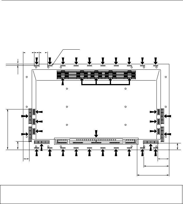
3.2.1 Heat dissipation
This unit has openings for effective ventilation at locations marked by arrows in the illustration below. To allow proper
dissipation of heat from the unit, avoid blocking or covering any of these openings.
96.5 35 75 |
Ø 5 |
||||
|
|
|
|
|
|
10
Fan (4 in number)
345
70 |
|
54 |
|
45 |
85 |
|
|
|
|
|
215 |
|
|
255 |
Air flow through the openings: All four fans exhaust hot air from the unit. All openings not assisted by fans serve as air inlets. If the unit is hung from or embedded into a wall, special operating temperature limits and other limitations may apply. Refer to 3.4 Special Installation.
18
Installation Conditions
3.2.2 Calculating heat quantity
.
For power consumption, allow for 600 VA ( =. 600 W) per unit. Since most of the power consumed is transformed into heat, power consumption may be regarded as roughly equal to generated heat.
1Conversion to calories
[W]x 0.86 = [kcal/h]
Heat generated per display: 600 W x 0.86 = 516 kcal/h
2Conversion to British Thermal Units (BTU)
[W]x 3.41 = [BTU/h] Heat generated per unit: 600 W x 3.41 = 2046 BTU/h
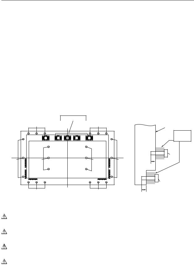
3.2.3 Product mounting holes
We recommend using mounting hardware available from Pioneer. If you use other mounting hardware, attach them to the unit using the M8-bolt holes provided in the unit. Remove the hole rivets, depending on the particular mounting hardware used. Tighten bolts with a torque between 50 and 80 kg.cm. Applying a torque beyond these limits may lead to nut failure.
•Locations of useble mount holes are shown below. (Caps, or plugs, can be removed by turning them with a coin or another device.)
Hole “a”: in 6 locations
Hole “b”: in 18 locations
|
Air outlet (Fan) |
|
|
Hole “b” |
|
Hole “b” |
|
|
Mounting Surface |
||
|
|
|
|
|
|
|
|
|
|
|
|
|
|
Mount |
|
|
|
|
|
|
hardware, |
|
|
|
|
|
The main |
etc. |
|
|
|
|
|
|
|
|
|
|
|
|
unit |
Hole “a” |
|
|
|
|
Center |
|
Bolt |
Hole “b” |
|
|
|
line |
|
|
Hole “a” |
|
Hole “a” |
Hole “b” |
|
10 to 17mm |
|
|
|
|
|
|
|
Hole “b” |
|
|
|
|
|
|
Bolt |
|
Hole “b” |
Center line |
Hole “b |
|
10 to 23mm |
|
|
|
|
Rear View |
|
Side View |
|
Always use a minimum four mounting holes, evenly distributed on opposite sides of both the horizontal and vertical center lines.
Use bolts that can be driven 10 to 17-mm into holes “a” or 10 to 23-mm into holes “b,” as shown in the Side View above.
Do not block or cover air outlets and openings for ventilation on the rear panel. Take precautions to prevent fouling walls behind the product with exhaust air discharged from the air outlets.
This unit incorporates glass components. Install only on flat surfaces.
19

Installation Conditions
This unit is designed to be mounted using four bolt holes. For additional safety, we recommend securing it at six to eight points on opposite sides of the horizontal and vertical center lines, as shown in the illustration below. Do not secure the unit at four points arranged in a single row, as shown below.
Methods for securing — Unfavorable examples
Methods for securing — Favorable examples
A. Secured at eight points |
|
|
|
|
|
|
|
|
|
|
|
B. Secured at six points |
|||||||||||||||||||||||||||||||
|
|
|
|
|
|
|
|
|
|
|
|
|
|
|
|
|
|
|
|
|
|
|
|
|
|
|
|
|
|
|
|
|
|
|
|
|
|
|
|
|
|
|
|
|
|
|
|
|
|
|
|
|
|
|
|
|
|
|
|
|
|
|
|
|
|
|
|
|
|
|
|
|
|
|
|
|
|
|
|
|
|
|
|
|
|
|
|
|
|
|
|
|
|
|
|
|
|
|
|
|
|
|
|
|
|
|
|
|
|
|
|
|
|
|
|
|
|
|
|
|
|
|
|
|
|
|
|
|
|
|
|
|
|
|
|
|
|
|
|
|
|
|
|
|
|
|
|
|
|
|
|
|
|
|
|
|
|
|
|
|
|
|
|
|
|
|
|
|
|
|
|
|
|
|
|
|
|
|
|
|
|
|
|
|
|
|
|
|
|
|
|
|
|
|
|
|
|
|
|
|
|
|
|
|
|
|
|
|
|
|
|
|
|
|
|
|
|
|
|
|
|
|
|
|
|
|
|
|
|
|
|
|
|
|
|
|
|
|
|
|
|
|
|
|
|
|
|
|
|
|
|
|
|
|
|
|
|
|
|
|
|
|
|
|
|
|
|
|
|
|
|
|
|
|
|
|
|
|
|
|
|
|
|
|
|
|
|
|
|
|
|
|
|
|
|
|
|
|
|
|
|
|
|
|
|
|
|
|
|
|
|
|
|
|
|
|
|
|
|
|
|
|
|
|
|
|
|
|
|
|
|
|
|
|
|
|
|
|
|
|
|
|
|
|
|
|
|
|
|
|
|
|
|
|
|
|
|
|
|
|
|
|
|
|
|
|
|
|
|
|
|
|
|
|
|
|
|
|
|
|
|
|
|
|
|
|
|
|
|
|
|
|
|
|
|
|
|
|
|
|
|
|
|
|
|
|
|
|
|
|
|
|
|
|
|
|
|
|
|
|
|
|
|
|
|
|
|
|
|
|
|
|
|
|
|
|
|
|
|
|
|
|
|
|
|
|
|
|
|
|
|
|
|
|
|
|
|
|
|
|
|
|
|
|
|
|
|
|
|
|
|
|
|
|
|
|
|
|
|
|
|
|
|
|
|
|
|
|
|
|
|
|
|
|
|
|
|
|
|
|
|
|
|
|
|
|
|
|
|
|
|
|
|
|
|
|
|
|
|
|
|
|
|
|
|
|
|
|
|
|
|
|
|
|
|
|
|
|
|
|
|
|
|
|
|
|
|
|
|
|
|
|
|
|
|
|
|
|
|
|
|
|
|
|
|
|
|
|
|
|
|
|
|
|
|
|
|
|
|
|
|
|
|
|
|
|
|
|
|
|
|
|
|
|
|
|
|
|
|
|
|
|
|
|
|
|
|
|
|
|
|
|
|
|
|
|
|
|
|
|
|
|
|
|
|
|
|
|
|
|
|
|
|
|
|
|
|
|
|
|
|
|
|
|
|
|
|
|
|
|
|
|
|
|
|
|
|
|
|
|
|
|
|
|
|
|
|
|
|
|
|
|
|
|
|
|
|
|
|
|
|
|
|
|
|
|
|
|
|
|
|
|
|
|
|
|
|
|
|
|
|
|
|
|
|
|
|
|
|
|
|
|
|
|
|
|
|
|
|
|
|
|
|
|
|
|
|
|
|
|
|
|
|
|
|
|
|
|
|
|
|
|
|
|
|
|
|
|
|
|
|
|
|
|
|
|
|
|
|
|
|
|
|
|
|
|
|
|
|
|
|
|
|
|
|
|
|
|
|
|
|
|
|
|
|
|
|
|
|
|
|
|
|
|
|
|
|
|
|
|
|
|
|
|
|
|
|
|
|
|
|
|
|
|
|
|
|
|
|
|
|
|
|
|
|
|
|
|
|
|
|
|
|
|
|
|
|
|
|
|
|
|
|
|
|
|
|
|
|
|
|
|
|
|
|
|
|
|
|
|
|
|
|
|
|
|
|
|
|
|
|
|
|
|
|
|
|
|
|
|
|
|
|
|
|
|
|
|
|
|
|
|
|
|
|
|
|
|
|
|
|
|
|
|
|
|
|
|
|
|
|
|
|
|
|
|
|
|
|
|
|
|
|
|
|
|
|
|
|
|
|
|
|
|
|
|
|
|
|
|
|
|
|
|
|
|
|
|
|
|
|
|
|
|
|
|
|
|
|
|
|
|
|
|
|
|
|
|
|
|
|
|
|
|
|
|
|
|
|
|
|
|
|
|
|
|
|
|
|
|
|
|
|
|
|
|
|
|
|
|
|
|
|
|
|
|
|
|
|
|
|
|
|
|
|
|
|
|
|
|
|
|
|
|
|
|
|
|
|
|
|
|
|
|
|
|
|
|
|
|
|
|
|
|
|
|
|
|
|
|
|
|
|
|
|
C.Secured at four points
(with mounting hardware attached to the sides)
20
Installation Conditions
D. Secured at four points (with mounting hardware attached horizontally)
(Take proper precautions to prevent pinching the power cord or signal cables)
3.2.4 Mounting surface warping
The display section incorporates glass. Before mounting the product, perform the following to confirm that the display is free of warps exceeding 1 mm.
1Referring to the illustration below, diagonally extend string of maximum 0.1-mm diameter through the bolt mount openings. Strings thus arranged should be completely free of slack.
2Measure the clearance (L) between the strings at their point of intersection. Distortion is expressed by: Distortion = L x 2.
3If L is found to be 0, pass the strings through the other bolt mount openings and repeat the measurements. Any value of L greater than 0 indicates the presence of distortion. If the measured values in both cases is 0, the distortion is negligible.
A
Mount
bolt
holes
Plasma Display Mount
Surface (Mount Brackets)
A
String
F
E
String
C
Magnified veiw of section A
A
DPoint E is the center point of string segment A-B.
Point F is the center point of string segment C-D.
Clearance between points E and F = L points E and F shown displaced for illustrative purposes
B
21
Installation Procedures
3.3 Installation Procedures
3.3.1 Transportation precautions
1 Any transportation of the unopened unit in its packaging should be done by more than two persons. To avoid breakage, do not lift the package by the packing bands.
2 When transporting or storing the unit, always position it vertically - never horizontally. Horizontal transportation or storage invalidates the product warranty.
3 In transportation or storage, never stack more than three units. This warning is also indicated on the upper face of the carton.
4 For transportation or storage, observe the warnings and instructions found on the upper surface of the carton.
5 The front of the display is glass-bearing. Always take precautions to prevent sharp objects from striking this side.
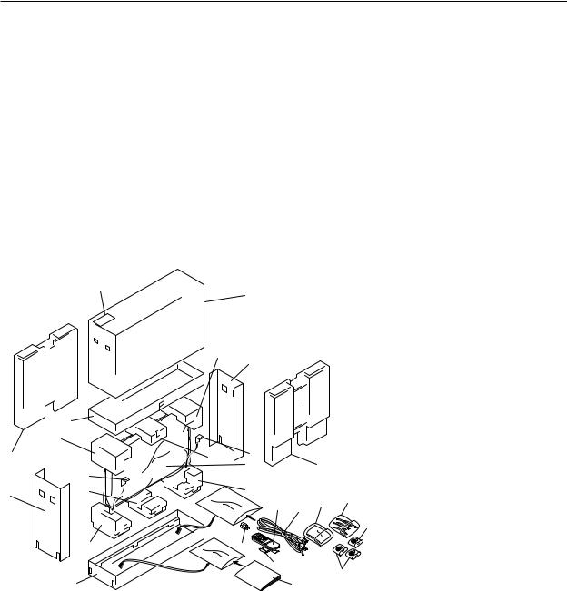
3.3.2 Unpacking
1) Package specifications: 1382 (W) x 888 (H) x 454 (D), 58.0 kg
17
|
2 |
|
5 |
22 |
|
|
11 |
3 |
9 |
|
8
4
|
|
Ref.No. |
Terms: |
|
|
1 |
1 |
Upper face of the carton |
|
|
|
|||
|
|
2 |
Carton cover |
|
|
|
3 |
Side carton |
|
7 |
3 |
4 |
Lower face of the carton |
|
5 |
Upper pad L |
|||
|
||||
|
|
6 |
11 |
|
12 |
||
|
||
|
10 |
23
6Upper pad C
7Upper pad R
8Under pad L
9Under pad C
|
|
21 |
|
10 |
Under pad R |
|
|
|
|
|
|
14 |
13 |
19 |
18 |
11 |
Carton spacer |
|
12 |
Miller mat |
|||
|
|
|
20 |
||
|
|
|
13 |
Power cord |
|
|
|
|
|
14 |
Remote control (CU-PDP002) |
15 |
|
|
|
15 |
2 manganese AA batteries, R6P |
|
|
|
|
|
20
16
16Operating manual
17Warrantee card
18Binder assembly
19Wiping cloth
20Adapter plug
(EURO Model, Taiwanese only)
21Front carton
22Rear carton
23AC conversion plug (Taiwanese only)
22
Installation Procedures
2)Unpacking procedures
1 Remove the packing bands.
2 Slowly lift and remove the upper carton [“top portion of the packaging”].
3 Lift and remove the reinforcement packaging. (Upper protective pad C is held in place by adhesive tape)
4 Remove the L and R upper cartons.
5 Remove the side, front, and rear cartons.
(At this stage, the product is supported by packing materials)
6 Remove the operating manual and accessories, which are secured to the lower carton by adhesive tape.
7 Remove the unit. (This should be performed by more than two persons)
3)Transportation of the unpacked unit
If it needs to be moved, the unit should be lifted by more than two persons.
•Avoid moving the unit by dragging it on the floor.
•Move the unit slowly, taking care to prevent scraping or striking the delicate front protective panel.
•Remove the protective film only after all work and preparations for the installation site, including clean-up following unpacking, are complete.
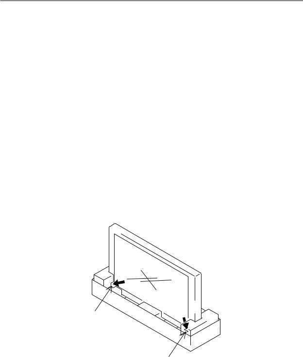
3.3.3 Temporary installation using packing materials
The lower carton and pads may be used as a temporary stand for the unit.
Connections to and from the unit can be made after the side, rear, and front cartons are removed. At this point, the power switch and remote control may also be operated, but this installation should be regarded as temporary. Always secure the unit to the mounting hardware after pre-installation wiring and adjustments are complete. Never attempt to move the unit while supported only by cartons.
Cutout allowing control
of using the remote
Cutout providing access to
the power switch
3.3.4 Re-packing
If the unit needs to be re-packed, observe the following guidelines:
•Pack by performing the steps described in 3.3.2 Unpacking in reverse order. The mirro mat must be positioned so that the shiny film surface faces outward and its soft surface faces inward (toward the unit).
•Restore all accessories to their original locations. Secure with adhesive tape to prevent damage during transportation.
•Check that no carton spacer is dislodged. Rearrange dislodged carton spacers so they are securely positioned between the unit and the lower pads, and secure with adhesive tape. This guards against instability during packaging or transportation.
23

Installation Procedures
3.3.5. Wiring
1)Connecting the power cable
•Refer to the section on Power Cord Connection on page 26 of the operating manual.
•For power source specifications, refer to 3.1 Installation Conditions, paragraph 11.
2)Connecting signal cables
(1) Connection to PCs
•Refer to the section with this heading in the operating manual, on pages 21 to 22.
(2) Connection to video units
•Refer to the section with this heading in the operating manual, on pages 23 to 25.
(3) Important Notes
•Use coaxial cables. As a rough guide, use 3C-2V cables for lengths up to 15 meters and 5C-2V cables for lengths up to 30 meters. Use thicker cables for computer signals, since these signals are more likely to degrade: 5C-2V cables, for example, for 15-meter lengths. Generally, thicker cables will produce more reliable connections. You can also improve signal quality by minimizing cable length.
•Video cables plugged into video inputs and outputs close to dimmers, neon signs, air-conditioning units, or cables for wired broadcasts may occasionally deliver slightly corrupted images.
3)Processing wires
•Be especially careful in selecting wiring lengths for permanent layouts. For temporary installations for occasional events, this isn’t quite so important.
•Arrange and secure cables so they will not be subject to direct load or physical force. For temporary installations, securing cables with string should be perfectly adequate. For permanent installations, secure by more reliable means.
24
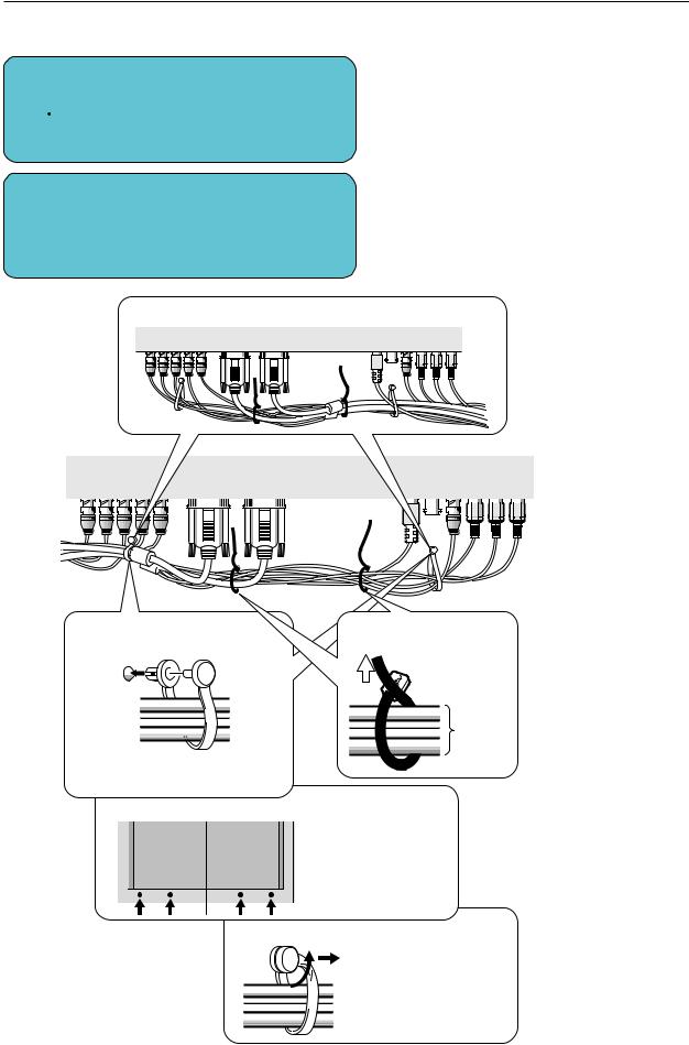
Installation Procedures
4) Arranging and securing cables with speed clamps and bead bands
1
2
Fasten cables using the supplied speed clamps.
 Remember that speed clamps are not easily removed, once fastened.
Secure cables with the supplied bead bands.
•Cables may also be drawn around to the right, viewed from this side.
* Display viewed from the rear.
1 Secure cables with speed |
2 Bundle cables using |
clamps. |
bead bands. |

 2 1
2 1
Cords
Insert part 1 into an opening in the rear cover, then insert part 2, as shown.
Fastening points for speed clamps
Bundled cables can be drawn to the left or right.
Depending on specific requirements, you may use the four openings indicated by solid circles (¶).
How to unlock the speed clamp
Use a pair of pliers to twist the clamp by at least a quarter-turn and pull outward. Remember that this procedure entails risk of damaging the clamp.
25
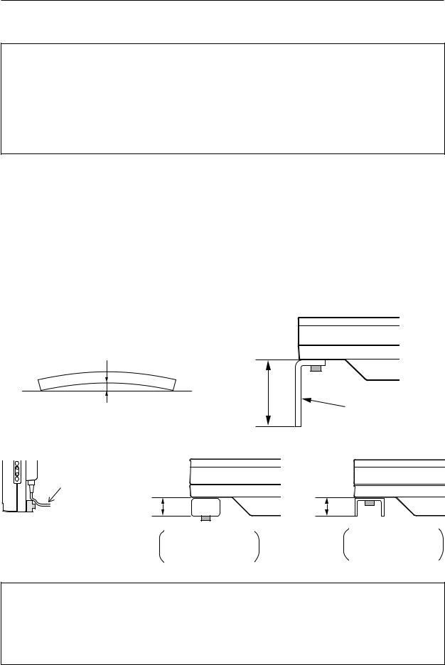
Special Installation (Mounting to fitting)
3.4 Special Installation
The unit can be hung from or embedded in a wall, but such special installations impose additional limitations on operating temperatures and other operational factors. Examine installation methods and the ambient conditions for your installation site while referring to paragraphs 3.1 to 3.3 in this manual.
Measurements discussed in this manual assume the following conditions:
•A 100% white input is supplied.
•Sufficient aging has been completed.
Make all measurements under identical conditions. The aging period required for correct measurement will be two and a harf hours, depending on the space available at the installation site.
3.4.1 Mounting to fittings
Observe the following guidelines when mounting the unit to fittings. Notes 2 to 7 apply to all cases of mounting-to- fitting.
1 During mounting to fitting, keep the space around the unit free of all objects and obstructions.
2 Any unit deformation/warping occurring as a result of installation should be less than 1 mm.
3 Never block or cover openings, aside from those shown as blocked on the page to the right.
4 The fittings should have a thickness of less than 20 mm. (This limit does not apply to fittings in examples 2 and 4 in the page to the right.)
5 L-shaped fittings should have a thickness of less than 100 mm.
6 The strength of the fittings must be adequate to bear the weight of the display.
7 Take precautions to avoid sharply bending the power cable.
1mm MAX |
|
|
Less than |
|
100 mm |
Maximum allowable deformation/ |
L-shaped fitting |
warping is 1 mm. |
|
Arrange the power cable so that minimum stress is placed on it.
Less than |
Less than |
|
20 mm |
||
20 mm |
||
|
No thickness limitations in examples 2 and 4 on the page to the right
No thickness limitations in examples 2 and 4 on the page to the right
*Operating Temperature Restrictions
•Ambient temperature: 0 to 40 °C
*Operating Temperature Restrictions for Upside-Down Installations
•Ambient temperature: 0 to 35 °C
This method of installation should be avoided in cases illustrated by examples 1 and 4 above.
26
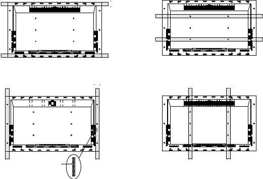
|
|
|
|
|
|
|
|
|
|
|
|
|
|
|
|
|
|
|
|
|
|
|
Special Installation (Mounting to fitting) |
||||||||||
|
|
|
|
|
|
|
|
|
|
|
|
|
|
|
|
|
|
|
|
|
|
|
|
|
|
|
|
|
|
|
|
|
|
Examples of Mounting to Fittings |
|
|
|
|
|
|
|
|
|
|
|
|
|
|
|
|
|
||||||||||||||||
|
Example 1) |
|
|
Less than |
Example 2) |
||||||||||||||||||||||||||||
|
|
|
|
|
|
|
|
|
|
|
|
|
|
|
|
|
|
|
35 mm |
|
|
|
|
|
|
|
|
|
|
|
|||
|
|
|
|
|
|
|
|
|
|
|
|
|
|
|
|
|
|
|
|
|
|
|
|
|
|
|
|
|
|
|
|
|
|
|
|
|
|
|
|
|
|
|
|
|
|
|
|
|
|
|
|
|
|
|
|
|
|
|
|
|
|
|
|
|
|
|
|
|
|
|
|
|
|
|
|
|
|
|
|
|
|
|
|
|
|
|
|
|
|
|
|
|
|
|
|
|
|
|
|
|
|
|
|
|
|
|
|
|
|
|
|
|
|
|
|
|
|
|
|
|
|
|
|
|
|
|
|
|
|
|
|
|
|
|
|
|
|
Less than |
|
|
||||
Example 3) |
35 mm |
Example 4) |
||||||
|
|
|
|
|
|
|
|
|
|
|
|
|
|
|
|
|
|
|
|
|
|
|
|
|
|
|
|
|
|
|
|
|
|
|
|
* Never block this
opening.
27
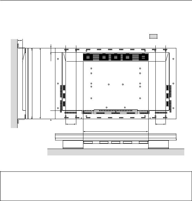
Special Installation (Hanging from wall)
3.4.2 Hanging on the wall
Carefully read the following before attempting to mount the unit on a wall, and observe the various limitations specified below. Be sure to mount the unit so that twisting, bending or any other deformation of the unit does not exceed 1 mm.
A |
Shaded areas ( |
) indicate attachment |
|
|
|
|
points for mounting hardware. |
|
|
48mm |
|
88mm
|
Avoid blocking or covering this |
|
104mm |
area on the upper and lower sides. |
104mm |
*Operating Temperature Restrictions
•Ambient temperature, regardless of clearance A: 0 to 40 °C (or 0 to 35 °C when the PDP-S02-LR speaker system is installed)
*Operating Temperature Restrictions for Upside-down Installations
•Ambient temperature, regardless of clearance A: 0 to 30 °C
NOTE: Different temperature restrictions apply to the PDK-5006. Refer to 4.5 Tiltable Plasma Display Mount Hardware. In wall-mounting installation, allow adequate space (a clearance of 300 mm or more) above and below the monitor set, as well as on the right and left.
28
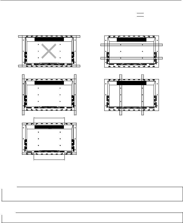
Special Installation (Hanging from wall)
Methods for Securing: Basic methods for securing are shown below.
Avoid blocking or covering areas, aside from those indicated by ( 
 ). The method indicated with cross-hatching should be avoided. Before attaching the unit to fittings, double-check that the thickness and height of the fittings and the number of fixing bolts is correct. (Also refer to 3.4.1 Mounting to Fittings.)
More than 700 mm
More than 700 mm
NOTE 1
Heated air is exhausted from the interior of the unit by fans. Before installation, consider the heat nesistance of the wall or other surfaces behind the unit. Exhaust temperatures can be 30°C( C higher than the outside temperature.
NOTE 2
For wall-mounting, bundle the cables so they don’t obstruct ventilation.
29
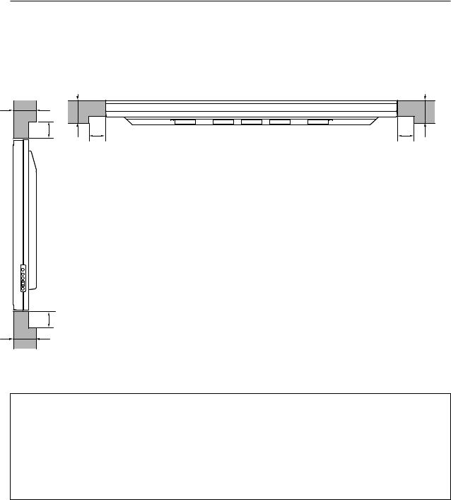
Special Installation (Embedding in the wall)
3.4.3 Embedding in the wall
Carefully read the following before trying to embed the unit in a wall, and make sure you observe all the limitations specified below. Be sure to mounting the unit so that twisting, bending, or any other deformation of the unit does not exceed 1 mm.
(1) Embedding in walls with space provided behind the unit.
B |
|
|
A |
B |
A |
X (Front of the unit)
A B
Y (Rear of the unit)
< Viewed from Above >
A
B
< Viewed from the Right Side >
* Operating Temperature Restrictions
|
Temperatures in space X and Y |
|
|
A: No restrictions; B: 0 to 170 mm |
0 to 40 °C |
|
|
A: No restrictions; B: 170 to 370 mm |
0 to 35 °C |
|
|
*Operating Temperature Restrictions for Upside-down Installations
*Upside-down mounting is unavailable when embedding/installing this device in a wall.
30
 Loading...