


Service
Manual
ORDER NO.
DEH-P250/XM/UC |
CRT2981 |
|
MULTI-CD CONTROL HIGH POWER CD PLAYER WITH FM/AM TUNER
DEH-P250XM/UC, XN/UC DEH-P2500 XM/UC, XN/UC DEH-P25 XM/UC, XN/UC
- This service manual should be used together with the following manual(s):
Model No. |
Order No. |
Mech. Module |
Remarks |
||||||
CX-3026 |
CRT2944 |
S10 |
CD Mech. Module:Circuit Description, Mech.Description, Disassembly |
||||||
|
|
|
|
|
|
|
|
|
|
|
|
|
|
|
|
|
|
|
|
|
|
|
|
|
|
|
|
|
|
|
|
|
|
|
|
|
|
|
|
|
|
|
|
|
|
|
|
|
|
For details, refer to "Important symbols for good services".
PIONEER CORPORATION |
4-1, Meguro |
1-Chome, Meguro-ku, Tokyo 153-8654, Japan |
PIONEER ELECTRONICS (USA) INC. |
P.O.Box 1760, Long Beach, CA 90801-1760 U.S.A. |
|
PIONEER EUROPE NV Haven 1087 |
Keetberglaan 1, |
9120 Melsele, Belgium |
PIONEER ELECTRONICS ASIACENTRE PTE.LTD. 253 Alexandra Road, #04-01, Singapore 159936
C PIONEER CORPORATION 2002 |
K-ZZA. OCT. 2002 Printed in Japan |
|
1 |
2 |
3 |
4 |
A SAFETY INFORMATION
CAUTION
This service manual is intended for qualified service technicians; it is not meant for the casual do-it-yourselfer. Qualified technicians have the necessary test equipment and tools, and have been trained to properly and safely repair complex products such as those covered by this manual.
Improperly performed repairs can adversely affect the safety and reliability of the product and may void the warranty. If you are not qualified to perform the repair of this product properly and safely, you should not risk trying to do so and refer the repair to a qualified service technician.
BWARNING
This product contains lead in solder and certain electrical parts contain chemicals which are known to the state of California to cause cancer, birth defects or other reproductive harm.
Health & Safety Code Section 25249.6 - Proposition 65
C
[ Important symbols for good services ]
DIn this manual, the symbols shown-below indicate that adjustments, settings or cleaning should be made securely. When you find the procedures bearing any of the symbols, be sure to fulfill them:
1.Product safety
You should conform to the regulations governing the product (safety, radio and noise, and other regulations), and should keep the safety during servicing by following the safety instructions described in this manual.
2. Adjustments
 To keep the original performances of the product, optimum adjustments or specification confirmation is indispensable. In accordance with the procedures or instructions described in this manual, adjustments should be performed.
3. Cleaning
E
For optical pickups, tape-deck heads, lenses and mirrors used in projection monitors, and other parts requiring cleaning, proper cleaning should be performed to restore their performances.
4. Shipping mode and shipping screws
To protect the product from damages or failures that may be caused during transit, the shipping mode should be set or the shipping screws should be installed before shipping out in accordance with this manual, if necessary.
|
5. Lubricants, glues, and replacement parts |
|
Appropriately applying grease or glue can maintain the product performances. But improper lubrication or applying |
|
glue may lead to failures or troubles in the product. By following the instructions in this manual, be sure to apply the |
F |
prescribed grease or glue to proper portions by the appropriate amount.For replacement parts or tools, the prescribed |
|
ones should be used. |
2 |
DEH-P250/XM/UC |
1 |
2 |
3 |
4 |

5 |
|
6 |
|
7 |
|
8 |
|
|
|
CONTENTS |
|
SAFETY INFORMATION ............................................................................................................................................ |
2 |
1. SPECIFICATIONS ....................................................................................................................................................... |
4 |
2. EXPLODED VIEWS AND PARTS LIST....................................................................................................................... |
6 |
2.1 PACKING............................................................................................................................................................... |
6 |
2.2 EXTERIOR............................................................................................................................................................. |
8 |
2.3 CD MECHANISM MODULE ............................................................................................................................... |
12 |
3. BLOCK DIAGRAM AND SCHEMATIC DIAGRAM................................................................................................... |
14 |
3.1 BLOCK DIAGRAM .............................................................................................................................................. |
14 |
3.2 OVERALL CONNECTION DIAGRAM(GUIDE PAGE) ........................................................................................ |
16 |
3.3 KEYBOARD UNIT ............................................................................................................................................... |
22 |
3.4 CD MECHANISM MODULE ............................................................................................................................... |
24 |
4. PCB CONNECTION DIAGRAM ................................................................................................................................ |
28 |
4.1 TUNER AMP UNIT ............................................................................................................................................. |
28 |
4.2 PANEL UNIT ....................................................................................................................................................... |
32 |
4.3 KEYBOARD UNIT ............................................................................................................................................... |
33 |
4.4 CD MECHANISM MODULE ............................................................................................................................... |
34 |
5. ELECTRICAL PARTS LIST ........................................................................................................................................ |
36 |
6. ADJUSTMENT ......................................................................................................................................................... |
40 |
6.1 CD ADJUSTMENT ............................................................................................................................................. |
40 |
6.2 CHECKING THE GRATING AFTER CHANGING THE PICKUP UNIT................................................................ |
42 |
6.3 ERROR MODE .................................................................................................................................................... |
44 |
7. GENERAL INFORMATION ....................................................................................................................................... |
45 |
7.1 DIAGNOSIS ........................................................................................................................................................ |
45 |
7.1.1 DISASSEMBLY .............................................................................................................................................. |
45 |
7.1.2 CONNECTOR FUNCTION DESCRIPTION .................................................................................................... |
47 |
7.2 PARTS ................................................................................................................................................................. |
48 |
7.2.1 IC .................................................................................................................................................................... |
48 |
7.2.2 DISPLAY......................................................................................................................................................... |
56 |
7.3 OPERATIONAL FLOW CHART........................................................................................................................... |
58 |
7.4 CLEANING .......................................................................................................................................................... |
59 |
8. OPERATIONS ........................................................................................................................................................... |
60 |
- CD Player Service Precautions
1.Before disassembling the unit, be sure to turn off the power. Unplugging and plugging the connectors during power-on mode may damage the ICs inside the unit.
2.To protect the pickup unit from electrostatic discharge during serviving, take an appropriate treat- ment(shorting-solder) by referring to "the DISASSEMBLY" on page 45.
3.After replacing the pickup unit, be sure to check the grating.(See p.42.)
A
B
C
D
E
F
DEH-P250/XM/UC |
3 |
|
|
5 |
6 |
7 |
8 |
1 |
2 |
3 |
4 |
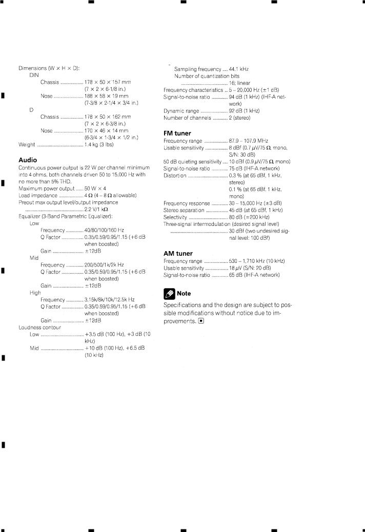
A1. SPECIFICATIONS
-DEH-P250/XM/UC, DEH-P250/XN/UC
B
C
D
E
F
4 |
DEH-P250/XM/UC |
1 |
2 |
3 |
4 |

5 |
|
6 |
|
7 |
|
8 |
|
|
|
- DEH-P2500/XM/UC, DEH-P2500/XN/UC, DEH-P25/XM/UC, DEH-P25/XN/UC
A
B
C
D
E
F
DEH-P250/XM/UC |
5 |
|
|
5 |
6 |
7 |
8 |
1 |
2 |
3 |
4 |
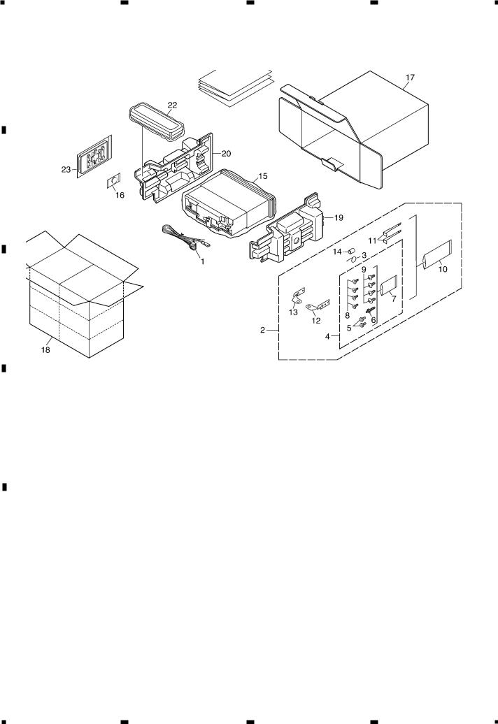
A2. EXPLODED VIEWS AND PARTS LIST
2.1 PACKING
B
C
NOTE:
D
-Parts marked by “*” are generally unavailable because they are not in our Master Spare Parts List.
-Screws adjacent to mark on the product are used for disassembly.
-For the applying amount of lubricants or glue, follow the instructions in this manual. (In the case of no amount instructions, apply as you think it appropriate.)
(1)PACKING SECTION PARTS LIST
|
|
|
Mark No. Description |
Part No. |
|
Mark No. Description |
Part No. |
||||||
|
|
|
|
|
|
|
|
|
|
|
|
||
|
|
|
|
1 |
Cord Assy |
CDE7060 |
* |
16 |
Battery |
CEX1065 |
|||
E |
2 |
Accessory Assy |
CEA3376 |
|
|
17 |
Carton |
See Contrast table(2) |
|||||
|
|
|
|
3 |
Spring |
CBH1650 |
|
|
18 |
Contain Box |
See Contrast table(2) |
||
|
|
|
|
4 |
Screw Assy |
CEA3445 |
|
|
19 |
Protector |
CHP2663 |
||
|
|
|
|
5 |
Fixing Screw |
BPZ20P060FZK |
|
|
20 |
Protector |
CHP2664 |
||
|
|
|
|
6 |
Screw |
CBA1002 |
|
|
21-1 |
Owner’s Manual |
See Contrast table(2) |
||
|
|
* |
7 |
Polyethylene Bag |
CEG-127 |
|
|
21-2 |
Installation Manual |
See Contrast table(2) |
|||
|
|
|
|||||||||||
|
|
|
|
8 |
Screw |
CRZ50P090FTC |
* |
21-3 |
Warranty Card |
See Contrast table(2) |
|||
|
|
|
|
||||||||||
|
|
|
|
9 |
Screw |
TRZ50P080FTC |
* |
21-4 |
Card |
See Contrast table(2) |
|||
* |
10 |
Polyethylene Bag |
CEG-158 |
* |
21-5 |
Caution Card |
See Contrast table(2) |
||||||
|
|
|
|
11 |
Handle |
CNC5395 |
|
|
22 |
Case Assy |
See Contrast table(2) |
||
F |
12 |
Holder |
CND1249 |
|
|
23 |
Remote Control Unit |
CXC1265 |
|||||
13 |
Holder |
CND1250 |
|
|
|
|
|
|
|||||
|
|
|
|
14 |
Bush |
CNV3930 |
|
|
|
|
|
|
|
|
|
|
|
15 |
Polyethylene Bag |
CEG1173 |
|
|
|
|
|
|
|
6 |
|
|
|
|
|
|
|
|
|
||||
|
|
|
DEH-P250/XM/UC |
|
|
|
|
||||||
|
|
|
|
|
|
|
|
|
|
|
|
|
|
1 |
2 |
3 |
4 |

5 |
|
6 |
|
7 |
|
8 |
|
|
|
(2) CONTRAST TABLE
DEH-P250/XM/UC, DEH-P250/XN/UC, DEH-P2500/XM/UC, DEH-P2500/XN/UC, DEH-P25/XM/UC and DEH-P25/XN/UC are constructed the same except for the following:
Mark No. Symbol and Description |
|
Part No. |
|
||
DEH-P250/XM/UC |
|
DEH-P2500/XM/UC |
DEH-P25/XM/UC |
||
17 Carton |
CHG4958 |
|
CHG4959 |
CHG4960 |
|
18 Contain Box |
CHL4958 |
|
CHL4959 |
CHL4960 |
|
21-1 Owner’s Manual |
CRD3686 |
|
CRD3688 |
CRD3688 |
|
21-2 |
Installation Manual |
CRD3687 |
|
CRD3689 |
CRD3689 |
* 21-3 |
Warranty Card |
CRY1070 |
|
Not used |
Not used |
* 21-4 Card |
Not used |
|
ARY1048 |
ARY1048 |
|
* 21-5 |
Caution Card |
Not used |
|
Not used |
CRP1294 |
22 Case Assy |
CXB3520 |
|
Not used |
Not used |
|
|
|
|
|
|
|
Mark No. Symbol and Description |
|
Part No. |
|
||
DEH-P250/XN/UC |
|
DEH-P2500/XN/UC |
DEH-P25/XN/UC |
||
17 |
Carton |
CHG4972 |
|
CHG4973 |
CHG4974 |
18 |
Contain Box |
CHL4972 |
|
CHL4973 |
CHL4974 |
21-1 |
Owner’s Manual |
CRD3686 |
|
CRD3688 |
CRD3688 |
21-2 |
Installation Manual |
CRD3687 |
|
CRD3689 |
CRD3689 |
* 21-3 |
Warranty Card |
CRY1070 |
|
Not used |
Not used |
* 21-4 |
Card |
Not used |
|
ARY1048 |
ARY1048 |
* 21-5 |
Caution Card |
Not used |
|
Not used |
CRP1294 |
22 |
Case Assy |
CXB3520 |
|
Not used |
Not used |
- Owner's Manual, Installation Manual
Model |
Part No. |
Language |
DEH-P250/XM/UC |
CRD3686 |
English, French, Spanish |
DEH-P250/XN/UC |
CRD3687 |
|
DEH-P2500/XM/UC |
CRD3688 |
English, French, Spanish |
DEH-P2500/XN/UC |
|
|
DEH-P25/XM/UC |
CRD3689 |
|
DEH-P25/XN/UC |
|
|
A
B
C
D
E
F
DEH-P250/XM/UC |
7 |
|
|
5 |
6 |
7 |
8 |

1 |
2 |
3 |
4 |
2.2 EXTERIOR
A
B
C
D
E
F
8 |
DEH-P250/XM/UC |
1 |
2 |
3 |
4 |

5 |
|
6 |
|
7 |
|
8 |
|
|
|
(1) EXTERIOR SECTION PARTS LIST
Mark No. Description |
Part No. |
Mark No. |
Description |
Part No. |
||||
|
|
|
|
|
|
|
||
1 |
Remote Control Unit |
CXC1265 |
46 |
Cover |
CNM6854 |
|||
2 |
Cover |
CNS7068 |
47 |
Panel |
CNS7245 |
|||
3 |
Screw |
ISS26P055FTC |
48 |
Gear |
CNV5997 |
|||
4 |
Screw |
BMZ30P040FZK |
49 |
Pin |
CNV6486 |
|||
5 |
Screw |
BSZ26P060FTC |
50 |
Lighting Conductor |
CNV6487 |
|||
6 |
Screw |
BSZ30P060FTC |
51 |
Arm |
CNV7400 |
|||
7 |
Screw |
BSZ30P200FTC |
52 |
Arm |
CNV7401 |
|||
8 |
Cord Assy |
CDE7060 |
53 |
Arm |
CNV7402 |
|||
9 |
Cable |
CDE7188 |
54 |
Arm |
CNV7403 |
|||
10 |
CD Mechanism Module(S10) CXK5600 |
55 |
Panel Unit |
CWM8758 |
||||
11 |
Case |
CNB2793 |
56 |
Socket(CN1950) |
CKS3550 |
|||
12 |
Earth Plate |
CNC8915 |
57 |
Connector(CN1951) |
CKS4462 |
|||
13 |
Cushion |
CNM4870 |
58 |
Holder Unit |
CXB9501 |
|||
14 |
Insulator |
CNM7935 |
59 |
Holder Unit |
CXB9502 |
|||
15 |
Insulator |
CNM8174 |
60 |
Damper Unit |
CXB9503 |
|||
16 |
Panel |
See Contrast table(2) |
61 |
Service Panel Unit |
CXX1691 |
|||
17 |
Tuner Amp Unit |
CWM8618 |
62 |
Screw |
IMS20P045FZK |
|||
18 |
Screw |
ASZ26P060FTC |
63 |
Detach Grille Assy |
See Contrast table(2) |
|||
19 |
Screw |
BPZ26P080FTC |
64 |
Screw |
BPZ20P100FZK |
|||
20 |
Screw |
BSZ26P160FTC |
65 |
Button(DISP) |
CAC7779 |
|||
21 |
Fuse(10A) |
CEK1208 |
66 |
Button(PAUSE) |
CAC7780 |
|||
22 |
FM/AM Tuner Unit |
CWE1646 |
67 |
Button(AUDIO) |
CAC7781 |
|||
23 |
Holder |
CND1054 |
68 |
Button(OPEN) |
CAC7782 |
|||
24 |
Pin Jack(CN351) |
CKB1059 |
69 |
Button(VOLUME) |
CAC7783 |
|||
25 |
Plug(CN981) |
CKM1376 |
70 |
Button(SELECT) |
CAC7784 |
|||
26 |
Connector(CN101) |
CKS3408 |
71 |
Button(SRC) |
CAC7785 |
|||
27 |
Plug(CN831) |
CKS3537 |
72 |
Button(FUNC) |
CAC7786 |
|||
28 |
Connector(CN721) |
CKS3835 |
73 |
Button(1-6) |
CAC7787 |
|||
29 |
Antenna Jack(CN401) |
CKX1056 |
74 |
Button(CLK, EQ) |
CAC7808 |
|||
30 |
Holder |
CND1237 |
75 |
Spring |
CBH2630 |
|||
31 |
Holder |
CND1352 |
76 |
Cover |
CNS7269 |
|||
32 |
Insulator |
CNM8245 |
77 |
Lighting Conductor |
CNV7421 |
|||
33 |
Heat Sink |
CNR1668 |
78 |
Rubber |
CNV7422 |
|||
34 |
Terminal(CN402) |
VNF1084 |
79 |
Keyboard Unit |
See Contrast table(2) |
|||
35 |
Holder Unit |
See Contrast table(2) |
80 |
LCD(LCD1901) |
See Contrast table(2) |
|||
36 |
Chassis Unit |
CXB9528 |
81 |
Connector(CN1901) |
CKS4524 |
|||
37 |
Button(EJECT) |
CAC7752 |
82 |
Holder |
CNC9757 |
|||
38 |
Screw(M2x2) |
CBA1176 |
83 |
Sheet |
CNM7647 |
|||
39 |
Washer |
CBF1038 |
84 |
Cushion |
CNM8092 |
|||
40 |
Spring |
CBH2650 |
85 |
Connector |
CNV6440 |
|||
41 |
Spring |
CBH2651 |
86 |
Lighting Conductor |
CNV7495 |
|||
42 |
Spring |
CBH2652 |
87 |
Grille Unit |
See Contrast table(2) |
|||
43 |
Spring |
CBH2653 |
88 |
Transistor(Q752, 901, 911) |
2SD2375 |
|||
44 |
Spring |
CBL1512 |
89 |
IC(IC301) |
PAL007A |
|||
45 |
Holder |
CND1254 |
90 |
IC(IC1902) |
TSOP4840SB1 |
|||
|
|
|
|
91 |
Holder |
See Contrast table(2) |
||
|
|
|
|
92 |
Screw |
See Contrast table(2) |
||
|
|
|
|
93 |
Choke Coil(L981) |
CTH1280 |
||
|
|
|
|
|
|
|
9 |
|
|
|
|
DEH-P250/XM/UC |
|
|
|||
|
|
|
|
|
|
|
|
|
5 |
6 |
7 |
8 |
A
B
C
D
E
F

1 |
2 |
3 |
4 |
(2) CONTRAST TABLE
A
DEH-P250/XM/UC, DEH-P250/XN/UC, DEH-P2500/XM/UC, DEH-P2500/XN/UC, DEH-P25/XM/UC and DEH-P25/XN/UC are constructed the same except for the following:
|
|
Mark No. Symbol and Description |
|
Part No. |
|
||
|
|
DEH-P250/XM/UC |
|
DEH-P2500/XM/UC |
DEH-P25/XM/UC |
||
|
|
||||||
|
|
16 Panel |
CNS6935 |
|
CNS7309 |
CNS7309 |
|
|
|
35 Holder Unit |
CXB6681 |
|
CXB6681 |
CXB6681 |
|
|
|
63 |
Detach Grille Assy |
CXB9601 |
|
CXB9602 |
CXB9603 |
|
|
79 Keyboard Unit |
CWM8635 |
|
CWM8635 |
CWM8636 |
|
B |
80 LCD(LCD1901) |
CAW1759 |
|
CAW1759 |
CAW1760 |
||
|
|
|
|
|
|
||
|
|
87 |
Grille Unit |
CXB9629 |
|
CXB9630 |
CXB9631 |
|
|
91 Holder |
Not used |
|
Not used |
CNV7619 |
|
|
|
92 Screw |
Not used |
|
Not used |
BMZ40P140FTC |
|
|
|
|
|
|
|
|
|
|
|
|
|
|
|
|
|
|
|
|
|
|
|
|
|
|
|
Mark No. Symbol and Description |
|
Part No. |
|
||
|
|
DEH-P250/XN/UC |
|
DEH-P2500/XN/UC |
DEH-P25/XN/UC |
||
|
|
16 |
Panel |
CNS6935 |
|
CNS7309 |
CNS7309 |
|
|
35 |
Holder |
CNC8659 |
|
CNC8659 |
CNC8659 |
C |
63 |
Detach Grille Assy |
CXB9601 |
|
CXB9602 |
CXB9603 |
|
|
|
79 |
Keyboard Unit |
CWM8635 |
|
CWM8635 |
CWM8636 |
|
|
80 |
LCD(LCD1901) |
CAW1759 |
|
CAW1759 |
CAW1760 |
|
|
87 |
Grille Unit |
CXB9629 |
|
CXB9630 |
CXB9631 |
|
|
91 |
Holder |
Not used |
|
Not used |
CNV7619 |
|
|
92 |
Screw |
Not used |
|
Not used |
BMZ40P140FTC |
|
|
||||||
D
E
F
10 |
DEH-P250/XM/UC |
1 |
2 |
3 |
4 |
5 |
|
6 |
|
7 |
|
8 |
|
|
|
A
B
C
D
E
F
DEH-P250/XM/UC |
11 |
|
|
5 |
6 |
7 |
8 |
1 |
2 |
3 |
4 |
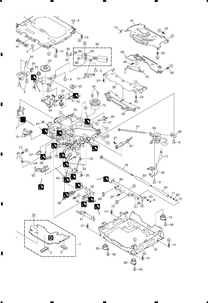
2.3 CD MECHANISM MODULE
A
B |
1 |
|
1
1
2 

 1
1 

C


 2
2
1
2 |
1 |
|
2 |
1 |
|
|
|
|
|
1 |
D |
|
1 |
|
|
3 |
1
2 |
|
2 |
|
|
|
|
1 |
1 |
|
|
|
|
|
1 |
|
|
1 |
1GEM1024
2GEM1045
3GEM1035
E
F
12 |
DEH-P250/XM/UC |
1 |
2 |
3 |
4 |

5 |
|
6 |
|
7 |
|
8 |
|
|
|
- CD MECHANISM MODULE SECTION PARTS LIST
Mark No. Description |
Part No. |
Mark No. Description |
Part No. |
|||
1 |
CD Core Unit(S10) |
CWX2708 |
|
46 |
Rack |
CNV7199 |
2 |
Connector(CN101) |
CKS4182 |
47 |
Holder |
CNV7201 |
|
3 |
Connector(CN701) |
CKS4188 |
48 |
Holder |
CNV7202 |
|
4 |
Screw |
BMZ20P035FTC |
49 |
Arm |
CNV7203 |
|
5 |
Screw |
BSZ20P040FTC |
50 |
Gear |
CNV7207 |
|
6 |
Screw(M2x4) |
CBA1362 |
51 |
Gear |
CNV7208 |
|
7 |
Screw(M2x3) |
CBA1511 |
52 |
Gear |
CNV7209 |
|
8 |
Screw(M2x3) |
CBA1527 |
53 |
Gear |
CNV7210 |
|
9 |
Washer |
CBF1037 |
54 |
Gear |
CNV7211 |
|
10 |
Washer |
CBF1038 |
55 |
Gear |
CNV7212 |
|
11 |
Washer |
CBF1060 |
56 |
Rack |
CNV7214 |
|
12 |
Spring |
CBH2390 |
57 |
Arm |
CNV7215 |
|
13 |
Spring |
CBH2606 |
58 |
Arm |
CNV7216 |
|
14 |
Spring |
CBH2607 |
59 |
Guide |
CNV7217 |
|
15 |
Spring |
CBH2608 |
60 |
Roller |
CNV7218 |
|
16 |
Spring |
CBH2609 |
61 |
Gear |
CNV7219 |
|
17 |
Spring |
CBH2610 |
62 |
Arm |
CNV7221 |
|
18 |
Spring |
CBH2611 |
63 |
Arm |
CNV7220 |
|
19 |
Spring |
CBH2612 |
64 |
Arm |
CNV7222 |
|
20 |
Spring |
CBH2613 |
65 |
Damper |
CNV7313 |
|
21 |
Spring |
CBH2614 |
66 |
Damper |
CNV7314 |
|
22 |
Spring |
CBH2615 |
67 |
Arm |
CNV7341 |
|
23 |
Spring |
CBH2616 |
68 |
Arm |
CNV7342 |
|
24 |
Spring |
CBH2617 |
69 |
Guide |
CNV7360 |
|
25 |
Spring |
CBH2620 |
70 |
Guide |
CNV7361 |
|
26 |
Spring |
CBH2621 |
71 |
Holder |
CNV7437 |
|
27 |
Spring |
CBH2641 |
72 |
Arm |
CNV7444 |
|
28 |
Spring |
CBH2642 |
73 |
Gear |
CNV7595 |
|
29 |
Spring |
CBH2643 |
74 |
Damper |
CNV7618 |
|
30 |
Spring |
CBH2659 |
75 |
Motor Unit(M1) |
CXB6007 |
|
31 |
Spring |
CBH2688 |
76 |
Chassis Unit |
CXB8728 |
|
* 32 |
Spring |
CBL1614 |
77 |
Screw Unit |
CXB8729 |
|
33 |
Shaft |
CLA3845 |
78 |
Gear Unit |
CXB8731 |
|
34 |
Frame |
CNC9962 |
79 |
Arm Unit |
CXB8732 |
|
35 |
Frame |
CNC9963 |
80 |
Arm Unit |
CXB8735 |
|
36 |
Bracket |
CNC9966 |
81 |
Arm Unit |
CXB8852 |
|
37 |
Bracket |
CNC9967 |
82 |
Motor Unit(M2) |
CXB8933 |
|
38 |
Arm |
CNC9968 |
83 |
Bracket |
CNC9985 |
|
39 |
Arm |
CNC9973 |
84 |
Screw |
JFZ20P020FTC |
|
40 |
Lever |
CNC9983 |
85 |
Screw(M2x5) |
EBA1028 |
|
41 |
Lever |
CNC9984 |
86 |
Screw |
JFZ20P020FTC |
|
42 |
Sheet |
CNM8134 |
87 |
Screw |
JGZ17P022FTC |
|
43 |
Collar |
CNV6906 |
88 |
Washer |
YE15FTC |
|
44 |
Guide |
CNV6925 |
89 |
Washer |
YE20FTC |
|
45 |
Arm |
CNV7198 |
90 |
Pickup Unit(Service)(P10) |
CXX1641 |
|
|
|
|
91 |
Screw |
IMS26P030FMC |
|
A
B
C
D
E
F
DEH-P250/XM/UC |
13 |
5 |
6 |
7 |
8 |
1 |
2 |
3 |
4 |
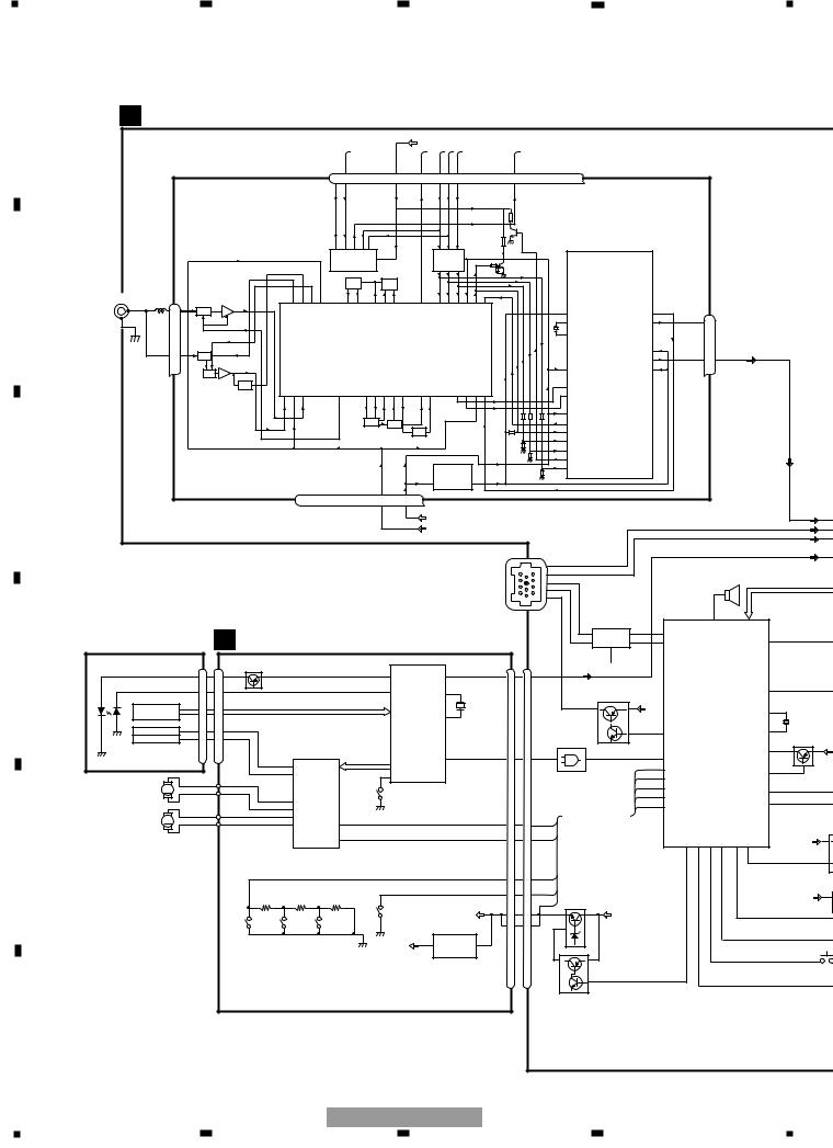
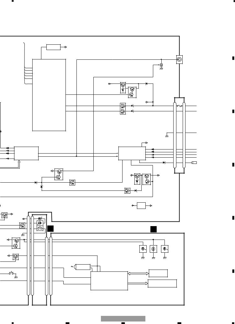
3. BLOCK DIAGRAM AND SCHEMATIC DIAGRAM
3.1 BLOCK DIAGRAM
A |
|
A TUNER AMP UNIT |
|
|
|
|
|
|
|
|
|
|
|
|
|
|
|
|
|
|
|
|
|
|
|
|
|
|
|
|
|
|
|
|
|||||
|
|
|
|
|
|
|
|
|
|
|
|
|
|
|
|
|
|
|
|
|
|
|
|
|
|
|
|
|
|
|
|
|
|
||||||
|
|
|
|
|
|
|
|
|
|
|
|
|
|
|
|
|
|
VDD |
|
|
|
|
|
|
|
|
|
|
|
|
|
|
|
|
|
|
|
|
|
|
|
|
|
FM/AM TUNER UNIT |
|
|
7 |
6 |
|
|
|
13 |
5 |
10 |
9 |
8 |
11 |
14 |
18 |
19 |
20 |
21 |
|
|
|
|
|
|
|
|
|
|
|
|
|||||
|
|
|
|
|
|
WC |
CE2 |
|
|
VDD |
SL |
DI |
CK |
CE1 |
NC |
DO |
NC |
NC |
NC |
NC |
|
|
|
|
|
|
|
|
|
|
|
|
|||||||
|
|
|
|
|
|
|
|
|
|
|
|
|
|
|
|
|
|
|
|
|
|
|
|
|
|
||||||||||||||
|
|
|
|
|
|
|
|
|
|
|
|
|
|
|
|
ROM_ |
|
|
|
|
|
|
|
|
|
|
|
|
|
|
|
|
|
|
|
|
|
|
|
|
|
|
|
|
|
|
|
|
|
|
|
IC 3 EEPROM |
|
|
|
|
IC 5 |
|
|
|
|
|
|
|
|
|
|
|
|
|
|
|
|
|
|
|
|||
|
|
|
|
|
|
|
|
|
|
|
|
|
5.0V |
|
|
|
|
|
5V |
← 3.3V |
|
|
|
|
|
|
|
|
|
|
|
|
|
|
|
|
|
|
|
|
|
|
|
|
|
|
|
|
|
|
|
|
OSC |
|
|
LPF |
|
|
|
|
|
|
|
|
|
|
|
|
|
|
|
|
|
|
|
|
|
|
|
B |
ANTENNA |
CN401 |
|
AM ANT |
|
FMRF |
|
|
|
|
|
|
|
|
|
|
|
|
|
|
|
|
|
|
|
|
|
|
|
|
|
|
|
|
|
|
|
|
|
|
|
|
|
|
|
|
|
|
|
|
|
|
|
|
|
|
|
|
|
|
|
|
|
|
|
|
|
|
|
|
|
|
|
|
|
|
|
|
|
|
|
|
1 |
|
ATT |
|
|
|
|
|
|
|
|
|
|
|
|
|
|
|
|
|
|
|
|
|
|
|
|
|
|
|
|
|
|
|
|
|
|
|
|
2 |
|
|
|
|
|
|
|
|
|
|
|
|
|
|
|
|
|
|
|
|
|
|
|
|
|
|
|
|
|
|
Rch 24 |
|
|
|
|
|
|
|
|
|
|
|
|
|
|
|
|
|
|
|
|
|
|
|
|
|
|
|
|
|
|
|
|
|
|
IC 2 |
|
|
|
|
|
|
|
|
|
|
|
|
|
|
|
FM ANT |
|
|
|
|
|
|
|
|
IC 1 |
|
|
|
|
|
|
|
|
|
|
|
|
|
2.5V |
|
|
|
|
|
|
|
|
|
|
|
|
|
|
|
|
|
|
|
|
|
|
|
|
|
|
|
|
|
|
|
|
|
|
|
|
|
|
|
|
|
|
|
|
|
|
|
|
|
|||
|
|
|
3 |
|
ATT |
|
|
|
|
|
|
|
|
3.3V |
|
|
|
|
|
|
|
|
|
|
|
|
|
|
|
|
|
|
Lch 23 |
|
|
|
|
|
|
|
|
|
|
FMRF |
|
|
|
|
|
MIXER, IF AMP |
|
|
|
|
|
|
|
|
|
|
|
|
|
|
|
|
|
|
|
|
|
||||||||
|
|
|
|
|
|
|
|
|
|
|
|
|
|
|
|
|
|
|
|
|
DET, FM MPX |
|
|
|
|
|
|
|
|
|
|
|
|||||||
|
|
|
|
|
|
|
|
|
|
|
|
|
|
|
|
|
|
|
|
|
|
|
|
|
|
|
|
|
|
|
|
|
|
|
|
|
|
||
|
|
|
|
|
ANT adj |
RF adj |
|
|
|
|
|
|
|
|
|
|
|
|
|
|
|
|
|
|
|
|
|
|
|
|
|
|
|
|
|
|
|
|
|
|
|
|
|
|
|
|
|
|
|
|
|
|
|
|
|
|
|
|
|
|
|
|
|
|
|
|
|
|
|
|
|
|
|
|
|
|
|
||
|
|
|
|
|
|
|
|
|
|
|
|
|
|
T51 |
CF52 |
|
|
|
|
|
|
|
|
|
|
|
|
|
|
|
|
|
|
|
|
|
|
||
|
|
|
|
|
|
|
|
|
|
|
|
|
|
|
|
|
|
|
|
|
|
|
|
|
|
|
|
|
|
|
|
|
|
|
|
|
|
||
|
|
|
|
|
|
|
|
|
|
|
|
|
|
|
|
|
|
CF51 |
|
|
|
|
|
|
|
|
|
|
|
|
|
|
|
|
|
|
|
|
|
|
|
|
|
|
|
|
|
|
|
RFGND |
OSCGND |
DGND |
AUDIOGND |
|
|
|
VDD 3.3 |
|
|
IC 4 |
|
|
|
|
|
|
|
|
|
|
|
|
|
|
|
|
|
|
|
C |
|
|
|
|
|
|
|
|
|
NC |
VCC |
3.3V |
3.3V |
← 2.5V |
2.5V |
|
|
|
|
|
|
|
|
|
|
|
|
|
|
|
|
|
|||||||
|
|
|
|
|
|
|
|
|
|
|
|
|
|
|
|
|
|
|
|
|
|
|
|
|
|
|
|
|
|
|
|||||||||
|
|
|
|
|
|
|
|
|
|
2 |
12 |
15 |
22 |
16 |
|
4 |
17 |
|
|
|
|
|
|
|
|
|
|
|
|
|
|
|
|
|
|
|
|
|
|
|
|
|
|
|
|
|
|
|
|
|
|
|
|
|
|
|
|
TUN 3.3V |
|
|
|
|
|
|
|
|
|
|
|
|
|
|
|
|
|
TUN L |
3 |
||
|
|
|
|
|
|
|
|
|
|
|
|
|
|
|
|
|
|
SYS 8.4V |
|
|
|
|
|
|
|
|
|
BUS+L |
|
|
|
|
|
|
|
BUS+L |
5 |
||
|
|
|
|
|
|
|
|
|
|
|
|
|
|
|
|
|
|
|
|
|
|
|
|
|
|
|
|
|
|
|
|
|
|
|
|
|
|||
|
|
|
|
|
|
|
|
|
|
|
|
|
|
|
|
|
|
|
|
|
|
|
|
|
|
|
|
|
|
BUS-L |
|
|
|
|
|
|
|
BUS-L |
6 |
|
|
|
|
|
|
|
|
|
|
|
|
|
|
|
|
|
|
|
|
|
|
|
|
CN101 |
|
|
|
|
|
|
|
|
|
|
|
CD L |
4 |
||
|
|
|
|
|
|
|
|
|
|
|
|
|
|
|
|
|
|
|
|
|
|
|
|
|
|
|
|
|
|
|
|
|
|
|
|
|
|
||
|
|
|
|
|
|
|
|
|
|
|
|
|
|
|
|
|
|
|
|
|
|
|
|
|
|
7 |
|
|
|
|
|
|
|
|
|
|
|
|
|
|
|
|
|
|
|
|
|
|
|
|
|
|
|
|
|
|
|
|
|
|
|
|
|
|
|
11 |
|
|
|
|
|
|
|
|
|
|
|
|
|
|
|
|
|
|
|
|
|
|
|
|
|
|
|
|
|
|
|
|
|
|
|
|
|
|
|
5 |
|
|
|
|
|
|
BUZZER |
|
|
|
|
||
|
|
|
|
|
|
|
|
|
|
|
|
|
|
|
|
|
|
|
|
|
|
|
|
|
|
1 |
|
|
|
|
|
|
|
|
|
|
|||
|
|
|
|
|
|
|
|
|
|
|
|
|
|
|
|
|
|
|
|
|
|
|
|
|
|
8 |
|
|
|
|
|
|
|
|
|
|
|
|
|
|
|
|
|
|
|
|
|
|
|
|
|
|
|
|
|
|
|
|
|
|
|
|
|
|
|
|
IP-BUS DRIVER |
|
|
|
|
|
100 |
|
|
|
|
||
|
PICKUP UNIT |
|
|
|
|
|
|
|
|
|
|
|
|
|
|
|
|
|
|
|
|
|
|
|
BUS- |
|
1 TX |
86 |
|
|
|
PEE |
|
|
|
|
|||
|
|
|
D CD CORE UNIT(S10) |
|
|
|
|
|
|
|
|
|
|
|
|
|
5 |
IC 101 |
TX |
|
|
|
|
|
|
|
|
||||||||||||
|
|
|
|
|
|
|
|
|
|
|
|
|
|
|
|
|
|
|
|
|
|
|
|
|
37 |
|
|||||||||||||
|
(SERVICE)(P10) |
|
|
|
|
|
|
|
|
|
|
|
|
|
|
6 HA12187FP 2 RX |
85 |
RX |
|
|
|
|
|
mute |
|
||||||||||||||
|
|
|
|
|
|
|
|
|
|
|
|
|
|
|
BUS+ |
|
|
|
|
|
|
|
|
|
|
|
|||||||||||||
|
|
|
|
|
|
|
|
|
|
|
|
|
|
|
8 |
|
|
|
|
|
|
|
|
|
|
|
|||||||||||||
|
|
|
|
|
|
|
|
|
|
|
|
|
|
|
|
|
|
|
|
|
|
|
|
|
|
|
|
|
24 |
|
|
|
|
|
|
|
|
|
|
|
|
|
|
|
|
CN101 |
|
|
|
|
|
|
|
|
|
|
|
|
|
|
CN701 |
|
|
|
|
|
IPPW |
|
IPPW |
|
|
|
|
|
|
|
|
||
D |
LASER |
|
|
|
|
|
|
|
|
|
|
|
|
|
|
|
|
|
|
|
CN721 |
|
|
|
|
|
|
|
|
|
|
|
|
||||||
|
|
|
|
|
Q101 |
|
|
|
|
|
|
|
|
|
|
|
|
|
|
|
|
|
|
|
|
|
|
|
|
|
|
|
|
||||||
|
|
|
|
|
|
|
|
|
|
|
|
|
|
|
|
|
|
|
LOUT |
|
|
|
|
|
|
|
|
|
|
|
|
|
|
||||||
DIODE |
|
|
LD+ |
|
14 |
|
|
|
|
|
|
|
|
|
1 |
LD |
LOUT |
20 |
|
8 |
14 |
|
|
|
|
|
|
|
|
|
|
|
|
|
|
|
|||
|
|
|
|
MD |
|
5 |
|
|
|
|
|
|
|
|
|
2 |
PD |
|
xtal |
23 |
|
|
|
|
|
|
|
Q101 |
|
|
|
|
|
|
|
|
SYSPW |
21 |
|
|
|
|
|
|
|
|
|
|
|
|
|
|
|
|
|
|
|
|
|
|
X201 |
|
|
|
|
|
|
|
|
|
|
|
|
|
|
|
|
||
|
|
HOLOGRAM |
|
|
|
|
|
|
|
|
AC, F, E, BD |
|
|
|
|
|
|
|
|
|
|
|
|
|
BU |
|
|
|
|
|
|
|
16 |
|
|||||
|
|
|
|
|
|
|
|
|
|
|
|
|
|
|
SERVO XTAL |
24 |
|
|
|
|
|
|
|
|
|
|
|
|
|
|
|
X1 |
|
||||||
|
|
UNIT |
|
|
|
|
|
|
|
|
|
|
|
|
|
|
|
|
|
|
|
|
|
|
|
|
|
|
|
|
|
|
X601 |
|
|||||
|
|
|
|
|
|
|
|
|
|
|
|
|
|
|
|
|
|
|
|
|
|
|
|
|
|
|
SYSTEM CONTROLLER |
|
|||||||||||
|
|
|
|
FOP |
|
|
FOP |
|
|
|
|
|
|
|
|
|
CONTROL, |
|
|
|
|
|
|
|
|
|
|
|
|
15 |
|
||||||||
|
|
|
|
|
|
|
|
|
|
|
|
|
|
|
|
|
|
|
|
|
|
|
|
|
|
71 |
|
|
|
|
|
|
|
|
|||||
|
|
FOCUS ACT. |
|
1 |
|
|
|
|
|
|
|
|
|
DSP, |
|
|
|
|
|
|
|
|
|
|
|
ASENBO |
|
|
|
|
X2 |
|
|||||||
|
|
TOP |
|
TOP |
|
|
|
|
|
|
|
|
|
|
|
|
|
|
|
|
|
|
|
|
|
|
|
|
|
|
|
||||||||
|
MONITOR TRACKING ACT. |
|
4 |
|
|
|
|
|
|
|
|
|
LPF, DAC |
|
|
|
|
|
|
|
|
|
|
|
|
|
|
|
IC 601(2/2) |
|
|
|
|||||||
|
|
|
|
|
|
|
|
|
|
|
|
|
|
|
|
|
|
|
|
IC 722 |
|
|
|
|
|
|
|
Q601 |
|
||||||||||
|
DIODE |
|
|
|
|
|
|
|
|
|
|
|
|
|
|
|
|
|
|
|
|
|
|
|
Q102 |
|
|
|
|
|
PE5341C |
|
|
||||||
|
|
|
|
|
|
|
|
|
|
|
|
|
|
|
|
|
|
12 |
|
|
|
|
|
|
|
|
|
AVREF |
83 |
|
|||||||||
|
|
|
|
|
|
|
|
|
|
|
|
|
|
|
|
|
IC 201 |
SO |
XSI |
|
|
|
2 |
4 |
|
|
66 |
|
|
|
|
|
|
|
|
||||
|
|
|
|
|
|
|
|
|
|
|
|
|
FD, TD, SD, MD |
16 |
6 |
|
|
|
XSI |
|
|
|
|
|
|
|
|
||||||||||||
|
|
|
|
|
|
|
|
|
12 |
|
|
|
|
|
|
|
|
|
|
|
|
|
|
|
|
|
|||||||||||||
|
|
|
|
|
|
|
|
|
FOP |
|
|
|
|
|
|
UPD63712GC |
|
|
|
|
|
|
|
|
|
|
59 |
CDLOEJ |
|
|
|
|
|
|
22 |
|
|||
|
|
|
|
|
|
|
|
|
13 |
TOP |
|
|
|
|
|
42 |
LIMIT |
|
|
|
|
|
|
|
|
TC7SET08FU |
|
|
61 |
|
|
|
|
|
adpw |
|
|||
|
|
|
|
|
|
|
|
|
|
|
|
|
|
|
|
|
|
|
|
|
|
|
|
|
CONT |
|
|
|
|
|
|
|
|
||||||
|
|
|
|
|
|
|
|
|
|
ACT,MOTOR |
|
|
|
|
|
|
|
|
|
|
|
|
|
|
|
|
|
79 |
|
|
|
|
|
|
|
|
|||
|
|
SPINDLE |
M |
|
|
|
|
|
|
|
|
|
|
|
|
|
|
|
|
|
|
|
|
|
|
|
DSCSNS |
|
|
|
|
|
9 |
|
|||||
|
|
|
|
|
|
|
|
DRIVER |
|
|
|
|
|
|
|
|
|
|
|
|
|
|
|
|
|
|
|
|
|
|
FLPILM |
|
|||||||
|
|
MOTOR |
|
|
|
|
|
16 |
HOME |
|
|
|
|
|
|
|
|
|
|
|
|
|
|
CLMP 63 |
|
|
|
|
|
||||||||||
|
|
|
|
|
|
|
|
|
SOP |
|
|
|
|
|
|
|
|
|
|
|
|
|
|
|
|
XTALEN |
|
|
|
|
|
|
8 |
|
|||||
|
|
|
|
|
|
|
|
|
|
|
|
|
|
|
|
|
|
|
|
|
|
|
|
|
|
|
|
80 |
|
|
|
|
|
ejectin |
|
||||
|
|
|
|
|
|
|
|
|
15 |
SOM |
|
|
|
|
|
|
|
|
|
|
|
|
|
|
|
|
|
|
|
VDSENS |
|
|
|
|
|
|
|
||
|
|
|
|
|
|
|
|
|
|
|
|
|
|
|
|
|
|
|
|
|
|
|
|
|
|
|
|
|
|
|
|
|
|
|
|
|
|||
|
LOADING/ CARRIAGE |
M |
|
|
|
|
|
17 |
LCOM |
|
|
|
|
|
|
|
|
|
|
|
LOEJ |
|
|
|
|
|
|
|
|
|
|
|
|
|
|
|
|
|
|
|
|
MOTOR |
|
|
|
|
|
18 |
LCOP |
|
LOEJ |
22 |
|
|
|
|
|
|
|
|
5 |
17 |
|
|
|
|
|
|
VDCONT |
|
KYDT |
dsens |
DPDT |
swvdd |
ILMPW |
|
|
||
|
|
|
|
|
|
|
|
|
|
|
|
CONT |
9 |
|
|
|
|
|
|
|
|
CONT |
7 |
15 |
|
|
|
|
|
|
|
BU |
|
||||||
E |
|
|
|
|
|
|
|
|
|
IC 301 |
|
|
|
|
|
|
|
|
|
|
|
|
|
|
|
|
|
|
64 |
95 |
90 |
96 |
41 |
20 |
|
|
|||
|
|
|
|
|
|
|
|
|
|
|
|
|
|
|
|
|
|
|
|
|
|
|
|
|
|
|
|
|
|
|
|
|
|
|
|
||||
|
|
|
|
|
|
|
|
|
BA5996FP |
|
|
|
|
|
|
|
|
|
|
|
|
|
|
|
|
|
|
|
|
|
|
|
|
|
|
|
|||
|
|
|
|
|
|
|
|
|
|
|
|
|
|
|
|
|
|
|
|
|
|
|
|
|
|
|
|
|
|
|
|
|
|
|
|
|
|||
|
|
|
|
|
|
|
|
|
|
|
|
|
|
|
|
|
|
|
|
|
|
DSCSNS |
6 |
16 |
|
|
|
|
|
|
|
|
|
|
|
|
|
|
|
|
|
|
|
|
|
|
|
|
|
|
|
|
|
|
|
|
|
|
|
|
|
|
|
|
|
|
|
|
|
|
|
|
|
|
|
|
|
||
|
|
|
|
|
|
|
|
|
|
|
|
|
|
|
|
|
|
|
|
|
|
CLMP |
11 |
11 |
|
|
|
|
|
|
|
|
|
|
|
|
|
VDD |
|
|
|
|
|
|
|
|
|
|
|
|
|
|
|
|
|
|
|
|
|
|
|
|
|
VDSENS |
|
|
|
|
|
|
|
|
|
|
|
|
|||
|
|
|
|
|
|
|
|
|
|
|
|
|
|
|
|
|
|
|
|
|
|
VD |
|
Q752 |
|
|
|
|
|
|
|
|
|
|
|
|
|||
|
|
|
|
|
|
|
|
|
|
|
|
|
|
|
|
|
|
|
|
|
|
|
|
|
|
|
|
|
|
|
|
|
|
|
|
|
|
||
|
|
|
|
|
|
|
|
|
|
|
|
|
|
|
|
CLAMP |
|
|
|
|
1 |
20 |
|
|
|
|
|
|
|
|
|
|
|
|
|
|
|
||
|
|
|
|
|
|
|
|
|
|
|
|
|
|
|
|
|
|
|
VD |
|
|
|
BU |
|
|
|
|
|
|
|
|
|
|
|
|||||
|
|
|
|
|
|
|
12EJ |
8EJ |
DSCSNS |
|
|
|
|
|
|
|
3.3V REGULATOR |
2 |
21 |
|
|
|
|
|
|
|
|
|
|
|
|
|
|
|
|||||
|
|
|
|
|
|
|
|
|
|
|
|
|
|
|
|
|
|
|
|
|
|
|
|
|
|
|
|
|
|
|
|
|
|||||||
|
|
|
|
|
|
|
|
|
|
|
|
|
|
|
|
|
|
|
|
|
|
|
|
|
|
|
|
|
|
|
|
|
|
|
|||||
|
|
|
|
|
|
|
|
|
|
|
|
|
|
|
|
|
3R3V |
3 |
IC 701 |
1 |
|
|
|
|
|
|
|
|
|
|
|
|
|
|
|
|
|
||
|
|
|
|
|
|
|
|
|
|
|
|
|
|
|
|
|
|
|
|
|
|
|
Q751 |
|
|
|
|
|
|
|
|
|
|
|
|
||||
|
|
|
|
|
|
|
|
|
|
|
|
|
|
|
|
|
|
|
|
|
|
|
|
|
|
|
|
|
|
|
|
|
|
|
|
||||
|
|
|
|
|
|
|
|
|
|
|
|
|
|
|
|
|
|
|
|
|
|
|
|
|
|
|
|
|
|
|
|
|
|
|
|
|
|
|
|
|
|
|
|
|
|
|
|
|
|
|
|
|
|
|
|
|
|
NJM2391DL1-33 |
|
|
|
|
|
|
|
|
|
|
|
|
|
|
|
DETACH SENSE |
|||||
|
|
|
|
|
|
|
|
|
|
|
|
|
|
|
|
|
|
|
|
|
|
|
|
|
|
|
|
|
|
|
|
|
|
|
|
|
|
||
F |
|
|
|
|
|
|
|
|
|
|
|
|
|
|
|
|
|
|
|
|
|
|
|
|
|
|
|
|
|
|
|
|
|
|
|
|
|
|
|
|
14 |
|
|
|
|
|
|
|
|
|
|
|
|
DEH-P250/XM/UC |
|
|
|
|
|
|
|
|
|
|
|
|
|
|
|
|
|
|
|
|
|||||
1 |
2 |
3 |
4 |
5 |
|
6 |
|
7 |
|
8 |
|
|
|
|
|
|
|
|
|
|
|
|
|
|
|
|
|
|
|
|
|
|
|
|
|
|
|
|
|
A |
|
|
|
|
|
|
|
RESET |
|
|
|
|
|
|
|
|
|
|
|
|
|
|
|
|
|
|
|
|
|
|
|
|
|
1 |
IC 651 |
2 |
VDD |
|
|
|
|
|
|
|
|
|
|
|
|
|
|
|
|
|
|
|
|
|
|
|
|
BD4834G |
|
|
|
|
|
|
|
|
|
|
|
|
|
|
|
|
|
||
|
|
|
|
|
|
|
|
|
|
|
|
|
|
|
|
|
|
|
|
|
|
|
|
|
||
|
|
|
|
|
|
|
|
|
|
|
|
|
|
|
|
|
|
|
|
|
|
|
CN351 |
PRE OUT |
|
|
|
|
|
|
|
|
11 |
|
|
|
|
|
|
|
|
|
RL |
|
|
|
|
RL |
|
4 |
|
RL |
|
|
|
|
|
|
|
reset |
|
|
|
|
|
|
|
|
|
|
|
|
|
|
|
|
|
|
|
|
|
|
|
|
|
|
|
|
|
|
|
|
|
|
|
|
|
|
|
|
|
Q351 |
|
|
|
|
|
|
|
|
CE2 |
32 |
TUNPCE2 |
|
|
|
|
|
|
|
|
|
|
|
|
|
|
|
|
|
|
|
|
|
|
|
|
CE1 |
99 |
TUNPCE1 |
|
|
|
|
|
|
|
|
|
|
|
|
|
|
|
|
|
|
|
|
|
|
|
|
DO |
94 |
|
|
|
|
|
|
|
|
|
|
|
|
|
|
|
|
|
|
|
|
||
|
|
|
TUNPDI |
|
|
|
|
|
|
|
|
|
|
|
|
|
|
|
|
|
|
|
|
|||
|
|
|
DI |
|
98 |
|
|
|
|
|
|
|
|
|
|
|
|
|
|
|
|
|
|
|
|
|
|
|
|
|
TUNPDO |
|
|
|
|
|
|
|
|
|
|
|
|
|
|
|
|
|
|
|
|
||
|
|
|
CK |
|
97 TUNPCK |
|
|
|
|
|
|
|
|
|
VDD REGULATOR |
|
|
|
|
|
|
|
|
|||
|
|
|
|
|
|
|
|
|
|
|
|
|
|
|
|
|
Q901 |
|
|
|
|
|
|
|
|
|
|
|
|
|
|
74 |
SL |
|
|
|
|
|
|
|
|
|
VDD |
|
|
|
|
|
|
|
|
|
B |
|
|
|
|
|
|
|
|
|
|
|
|
|
|
|
|
|
|
Q902 |
|
|
|
|
|
|
|
|
|
|
|
|
|
|
SYSTEM CONTROLLER |
|
|
|
|
|
|
|
|
|
|
|
|
|
|
|
|
|
|
||
|
|
|
|
|
|
IC 601(1/2) |
DALMON |
10 |
|
|
|
|
|
|
|
|
|
|
|
|
|
|
|
|
||
|
|
|
|
|
|
PE5341C |
|
|
|
|
|
|
|
|
|
|
|
|
|
CN981 |
|
|
|
|||
|
|
|
|
|
|
|
|
|
|
|
|
|
|
|
|
|
|
|
|
|
|
|
|
|
|
|
|
|
|
|
|
|
|
|
|
|
|
|
|
|
|
|
BACKUP SENSE |
|
BU |
|
|
|
|
|
|||
|
|
|
|
|
|
|
|
bsens |
93 |
|
|
|
|
|
Q931 |
|
|
|
|
BU |
16 |
FUSE |
16 |
BACK UP |
||
|
|
|
|
|
|
|
|
|
|
|
|
|
|
|
|
|
|
|
|
|
10A |
|
|
|||
|
|
|
|
|
|
|
|
|
|
|
|
|
|
|
|
|
|
|
|
|
|
|
|
|
|
|
|
|
|
|
|
|
|
|
asens |
92 |
|
|
|
|
|
|
|
|
ACC |
|
|
14 |
|
14 |
ACC |
||
|
|
|
|
|
|
|
|
|
|
|
|
|
|
|
|
|
|
|
|
|
|
|||||
|
|
|
|
|
|
|
|
|
|
|
|
|
|
|
|
ACC SENSE |
|
|
|
|
|
|
|
|
||
|
|
|
|
|
|
|
|
|
|
|
|
|
|
|
|
|
|
|
|
|
|
|
15 |
|
15 |
GND |
|
|
|
|
|
|
|
|
|
|
|
|
|
|
|
|
|
|
|
|
|
|
|
|
|
|
C |
|
|
ELECTRONIC VOLUME/ |
|
|
|
|
|
|
|
|
|
|
|
POWER AMP |
|
BU |
|
|
|
|
||||||
TUN L |
3 |
SOURCE SELECTOR |
|
|
|
|
|
|
|
|
|
|
|
20 |
|
|
|
|
|
|
||||||
IN2-L |
|
|
|
|
|
|
|
|
|
|
|
|
|
|
|
|
|
|
23 |
|
|
|
|
FL- |
||
+L |
5 |
|
|
|
|
|
|
|
|
|
|
|
|
|
|
|
|
|
FL- |
|
7 |
|
7 |
|||
IN4+L |
|
|
|
|
|
|
|
|
|
|
|
|
|
|
|
|
|
21 |
|
|
||||||
L |
6 |
IC 131 |
|
10 |
|
|
|
|
|
|
|
|
|
14 |
|
IC 301 |
|
FL+ |
|
5 |
|
5 |
FL+ |
|||
IN4-L |
|
|
|
|
|
|
|
|
|
|
FLIN |
|
3 |
|
|
|||||||||||
|
|
PML003AM |
FL |
|
|
|
|
|
|
|
|
|
12 |
PAL007A |
|
RL- |
|
8 |
|
8 |
RL- |
|||||
|
4 |
|
|
|
|
RL 11 |
|
|
|
|
|
|
|
|
|
RLIN |
|
|
RL+ |
5 |
|
6 |
|
6 |
||
|
IN3-L |
|
|
|
|
|
|
|
|
|
|
|
|
|
|
MUTE |
STBY |
|
|
|
|
RL+ |
||||
|
|
|
|
|
|
|
|
|
|
|
|
|
|
|
|
B.REMOTE |
|
|
|
|
|
|
||||
|
|
|
|
|
|
|
|
|
|
|
|
|
|
|
|
|
22 |
4 |
25 |
|
|
|
11 |
|
11 |
B.REM |
|
|
|
|
|
|
|
|
MUTE |
|
|
|
|
|
|
|
|
|
|
|
|
|
|
||||
|
|
|
|
|
|
|
|
|
|
|
|
|
|
|
|
|
|
|
|
|
|
|
|
|
||
|
|
|
|
|
|
|
|
Q502 |
|
|
|
|
|
|
|
|
|
|
|
|
|
|
|
|
|
|
|
|
|
|
|
|
|
BU |
|
|
|
|
|
|
|
|
|
|
SYS 8.4V REGULATOR |
|
|
|
|
||||
|
|
|
|
|
|
|
|
|
|
|
|
|
|
|
|
|
|
Q911 |
|
Q912 |
|
|
|
|
|
|
|
|
|
|
|
|
|
|
|
|
MUTE |
|
|
|
|
|
|
SYS 8.4V |
|
|
|
BU |
|
|
|
|
|
|
|
|
|
|
|
|
|
|
|
|
|
|
|
|
|
|
|
|
|
|
|
|
|
|
|
|
|
|
|
|
|
|
|
|
|
|
Q301 |
|
|
|
|
|
|
|
|
|
|
|
|
|
|
|
|
|
|
|
|
|
|
|
|
|
|
|
|
|
|
|
|
|
|
Q501 |
|
Q913 |
|
|
|
|
|
|
|
|
|
|
|
|
|
|
|
|
|
|
|
|
|
|
|
|
|
|
|
|
|
|
|
|
|
|
|
|
|
|
|
|
|
|
|
|
|
|
|
|
|
|
|
|
|
|
|
|
|
|
|
D |
|
|
|
|
|
|
|
|
|
|
|
|
|
|
|
|
|
|
|
|
|
SYSPW |
|
|
|
|
|
|
|
|
|
|
|
|
|
|
|
|
|
|
|
|
|
|
|
TUNER 3.3V REGULATOR |
|
|
|
|
||||
|
|
|
|
|
|
|
|
|
|
|
|
|
|
|
|
|
|
|
IC 921 |
|
|
|
|
|
|
|
X601 |
|
|
|
|
|
|
|
|
|
|
|
|
|
|
|
|
TUN 3.3V |
3 |
|
1 |
SYS 8.4V |
|
|
|
|
|
|
|
|
|
|
|
|
|
|
|
|
|
|
|
|
|
|
|
|
|
|
|
|||||
|
|
|
|
|
|
|
|
|
|
|
|
|
|
|
|
|
|
|
|
|
|
|
|
|||
Q601 |
|
|
|
|
|
|
|
|
|
|
|
|
|
|
|
|
|
|
BA033FP |
|
|
|
|
|
||
|
|
|
|
|
|
|
|
|
|
|
|
|
|
|
|
|
|
|
|
|
|
|
|
|
|
|
|
VDD |
CN831 |
|
|
|
|
|
|
|
|
|
|
|
|
|
|
|
|
|
|
|
|
|
|
|
|
|
|
|
|
|
|
|
|
|
|
|
|
|
|
|
|
|
|
|
|
|
|
|
|
|
|
|
|
|
|
BU |
5 |
5 |
|
|
|
|
|
|
|
|
|
|
|
|
|
|
|
|
|
|
|
|
|
|
|
|
Q831 |
6 |
6 |
|
|
|
|
|
|
|
|
|
|
|
|
|
|
|
|
|
|
|
|
|
|
|
|
|
|
B PANEL UNIT |
|
|
|
|
|
|
|
|
|
|
|
C KEYBOARD UNIT |
|
||||||||
|
|
|
|
8 |
8 |
S1970 |
|
|
|
|
|
|
|
|
|
|
|
|
||||||||
|
|
|
|
9 |
9 |
EJECT |
|
CN1901 |
|
|
|
|
|
|
|
|
|
|
|
|
|
|
|
|
|
|
|
|
Q961 |
|
|
|
|
|
|
|
|
|
|
|
|
|
|
|
|
|
|
|
|
|
|
||
|
|
ILB |
|
|
|
|
|
|
|
|
|
|
|
|
|
|
|
|
|
|
|
|
|
|
|
|
BU |
|
|
7 |
7 |
4 |
9 |
ILB |
|
|
|
|
|
|
|
|
|
|
|
|
|
|
|
|
|
|
|
|
|
|
BL+B |
|
|
|
|
|
|
|
|
|
|
|
|
|
|
|
|
|
|
|||||
|
|
|
|
10 |
10 |
5 |
8 |
|
|
|
|
|
|
|
|
|
|
|
|
|
|
|
|
|
|
|
|
|
|
|
|
|
|
|
|
|
|
|
|
|
|
|
|
|
|
|
|
|
E |
||||
|
|
|
|
|
|
|
|
|
|
|
|
|
|
|
|
|
|
|
|
|
|
|
|
|
|
|
|
|
Q962 |
|
|
|
|
|
|
|
|
|
|
|
|
|
|
|
|
|
|
|
|
|
|
|
|
|
|
Q971 |
|
|
|
|
|
SWVDD |
|
|
|
|
|
|
|
|
|
|
|
|
|
|
|
|
|
|
VDD |
|
SWDVDD |
2 |
2 |
2 |
11 |
|
|
|
|
|
|
|
|
|
|
|
|
|
|
|
|
|
|
||
|
|
|
|
|
|
|
|
|
|
|
|
|
|
|
|
|
|
|
|
|
|
|||||
|
|
|
|
|
|
|
|
|
|
REMOTE CONTROL SENSOR |
|
|
|
|
|
|
|
|
|
|
|
|
||||
|
|
|
DPDT |
|
|
|
|
DPDT |
|
OPT IN |
IC 1902 |
|
3 |
|
|
|
|
|
|
|
|
|
|
|
|
|
|
|
|
11 |
11 |
10 |
3 |
|
|
1 |
|
|
|
|
|
|
|
|
|
|
|
|
|||||
|
|
|
|
|
|
|
TSOP4840SB1 |
|
|
|
|
|
|
|
|
|
|
|
|
|
|
|||||
|
S801 |
|
|
|
|
|
|
|
|
|
17 |
55 |
|
11 |
|
|
|
|
|
|
|
|
|
|
||
|
|
|
|
|
|
|
|
|
|
|
|
RFM |
VDD |
VLCD |
|
|
|
|
|
|
|
|
|
|
||
|
|
|
|
|
|
|
|
|
|
|
|
|
|
KEY DATA |
|
|
|
KEY MATRIX |
|
|
|
|
||||
DETACH SENSE |
|
|
|
|
|
|
|
|
|
|
18 |
|
DPDT |
|
LCD DRIVER/ |
|
|
|
|
|
|
|
|
|
|
|
|
|
|
KYDT |
|
|
|
|
KYDT |
|
|
|
|
|
|
|
|
|
|
|
|
|
|
|
|
||
|
|
|
14 |
14 |
8 |
5 |
|
|
|
|
|
|
|
KEY CONTROLLER |
|
|
|
|
|
|
|
|
|
|||
|
|
|
|
|
|
|
|
|
|
|
|
20 |
|
KTDT |
|
IC 1901 |
|
|
|
|
|
LCD |
|
|
|
|
|
|
|
|
|
|
|
|
|
|
|
|
|
|
|
PD6340A |
|
|
|
|
|
|
|
|
|
||
|
|
|
|
|
|
|
|
|
|
|
|
|
|
|
|
|
|
|
|
|
|
|
|
|
|
|
|
|
|
|
|
|
CN1951 |
|
|
|
|
|
|
|
|
|
|
|
|
|
|
|
|
|
|
|
|
|
|
|
|
|
CN1950 |
|
|
|
|
|
|
|
|
|
|
|
|
|
|
|
|
|
|
|
F |
|
|
|
|
|
|
|
|
|
|
|
|
|
|
|
|
|
|
|
|
|
|
|
|
|
|
|
|
|
|
|
|
|
|
|
|
|
|
|
|
|
|
|
|
DEH-P250/XM/UC |
|
|
|
|
|
|
|
15 |
||
|
|
|
|
|
|
5 |
|
|
|
|
|
|
|
6 |
|
|
|
|
|
|
|
7 |
|
|
|
8 |
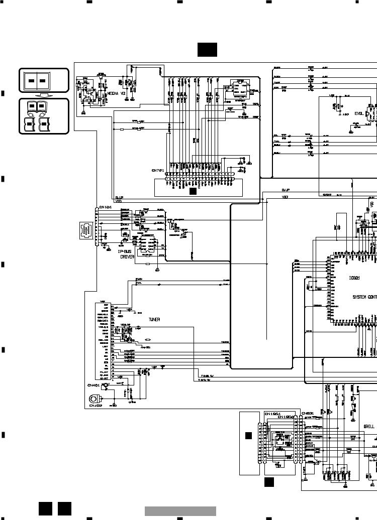
1 |
2 |
3 |
4 |
3.2 OVERALL CONNECTION DIAGRAM(GUIDE PAGE)
Note: When ordering service parts, be sure to refer to “EXPLODED VIEWS AND PARTS LIST” or “ELECTRICAL
A |
PARTS LIST”. |
A-a |
|
|
|
||
|
|
|
|
|
|
Large size |
|
A-a |
A-b |
SCH diagram |
|
|
|
||
A-a |
A-b |
Guide page |
|
A-a |
A-b |
Detailed page |
FM:-31.0dBs |
|
|
R4721 |
AM:-31.0dBs |
|
|
0R0 |
IP-BUS:+2.2dBs |
B |
|
CD:0dBs |
|
|
|
||
|
|
|
|
|
|
|
CD:0dBs |
|
|
|
D CN701 |
|
|
IP-BUS:+2.2dBs |
|
C |
|
IP-BUS |
|
|
|
|
|
|
|
|
R9101 |
|
|
|
0R0 |
|
|
|
PE5 |
|
|
FM(30%):-30.0dBs |
|
|
|
AM(30%):-30.0dBs |
|
D |
|
|
|
|
|
FM/AM |
R9403 |
|
|
UNIT TUNER |
0R0 |
|
|
|
|
E |
|
|
SW SENSE DETACH |
|
|
|
|
|
|
|
EJECT |
|
|
|
C |
|
|
|
CN1901 |
F |
|
|
B UNITPANEL |
|
|
|
|
16 |
A B |
DEH-P250/XM/UC |
|
|
|
||
1 |
2 |
3 |
4 |
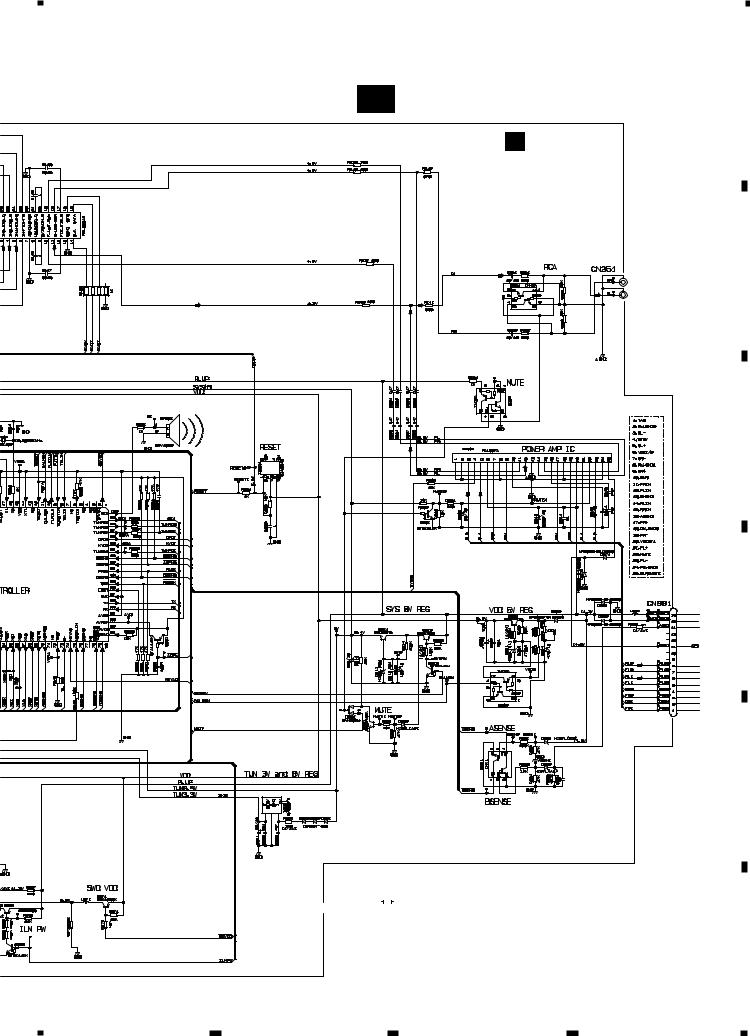
5 |
|
6 |
|
7 |
|
8 |
|
|
|
A-b
A
A TUNER AMP UNIT
FM:-5.9dBs
AM:-5.9dBs
IP-BUS:+10.3dBs
CD:+10.1dBs
5341C
FM:-6.66dBs
AM:-6.66dBs
IP-BUS:+9.54dBs
CD:+9.34dBs
REAR
R CH
REAR
L CH
600 H
BACKUP
GND
ACC
B.REM
RL—
FL—
RL+
FL+
RR—
FR—
RR+
FR+
FM:+30dBs
AM:+20dBs
IP-BUS:+36dBs
CD:+36dBs
NOTE : |
|
|
||||||
|
|
|
|
|
|
Symbol indicates a resistor. |
Decimal points for resistor |
|
|
|
|
|
|
||||
|
|
|
|
|
|
No differentiation is made between chip resistors and |
||
|
|
|
|
|
|
and capacitor fixed values |
||
|
|
|
|
|
|
discrete resistors. |
||
|
|
|
|
|
|
are expressed as : |
||
|
|
|
|
|
|
Symbol indicates a capacitor. |
2.2 ← |
2R2 |
|
|
|
|
|
|
No differentiation is made between chip capacitors and |
0.022 |
←R022 |
|
|
|
|
|
|
discrete capacitors. |
|
|
|
|
A |
17 |
|
DEH-P250/XM/UC |
||||
|
|
|||
|
|
|
|
B
C
D
E
F
5 |
6 |
7 |
8 |
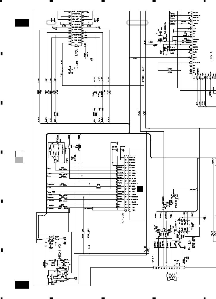
1 |
2 |
3 |
4 |
A-b |
1 |
2 |
A
FM:-31.0dBs |
AM:-31.0dBs BUS:+2.2dBs |
CD:0dBs |
B |
IP- |
|
C
A-a A-b
D |
CN701 |
|
|
|
D |
|
|
CD:0dBs |
E |
|
|
R4721 |
0R0 |
-BUS:+2.2dBs |
|
|
IP |
F
A-a
IP-BUS
|
|
R9101 |
0R0 |
|
|
|
|
|
|
|
|
|
|
|
|
|
|
|
|
18 |
DEH-P250/XM/UC |
1 |
2 |
3 |
4 |
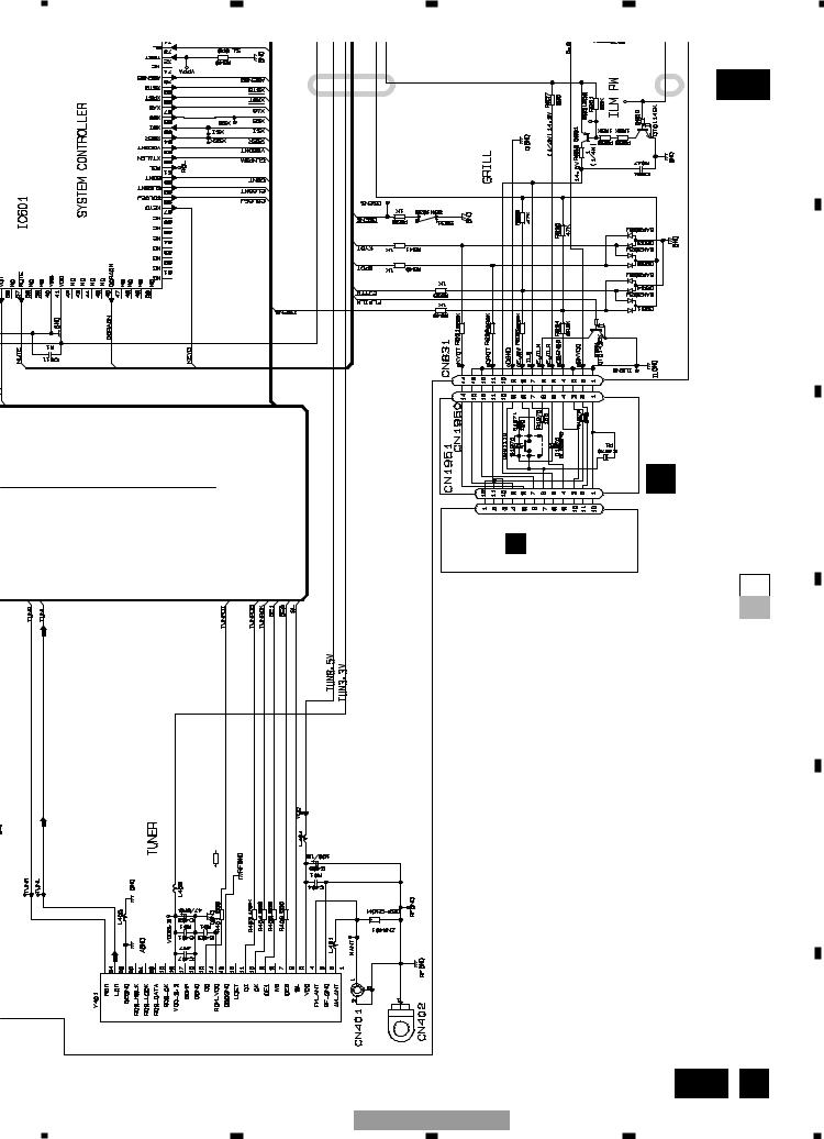
|
5 |
6 |
7 |
|
8 |
|
|
|
|
3 |
4 |
A-b |
|
PE5341C |
|
|
|
|
|
A |
|
|
|
|
|
|
|
|
|
|
DETACH SENSE SW |
|
|
|
|
|
|
|
|
|
B |
|
|
|
EJECT |
PANEL UNIT |
|
|
|
|
|
|
B |
|
C |
|
|
|
C |
CN1901 |
|
|
|
|
|
|
|
|
A-b |
|
|
|
|
|
|
A-a |
|
|
|
|
|
|
D |
|
R9403 |
0R0 |
|
|
|
E |
FM(30%):-30.0dBs |
AM(30%):-30.0dBs |
|
|
|
|
|
|
FM/AM TUNER UNIT |
|
|
|
|
|
|
|
|
|
|
|
F |
|
|
|
|
|
A-a |
B |
|
|
|
DEH-P250/XM/UC |
|
|
19 |
|
5 |
6 |
7 |
|
8 |
|
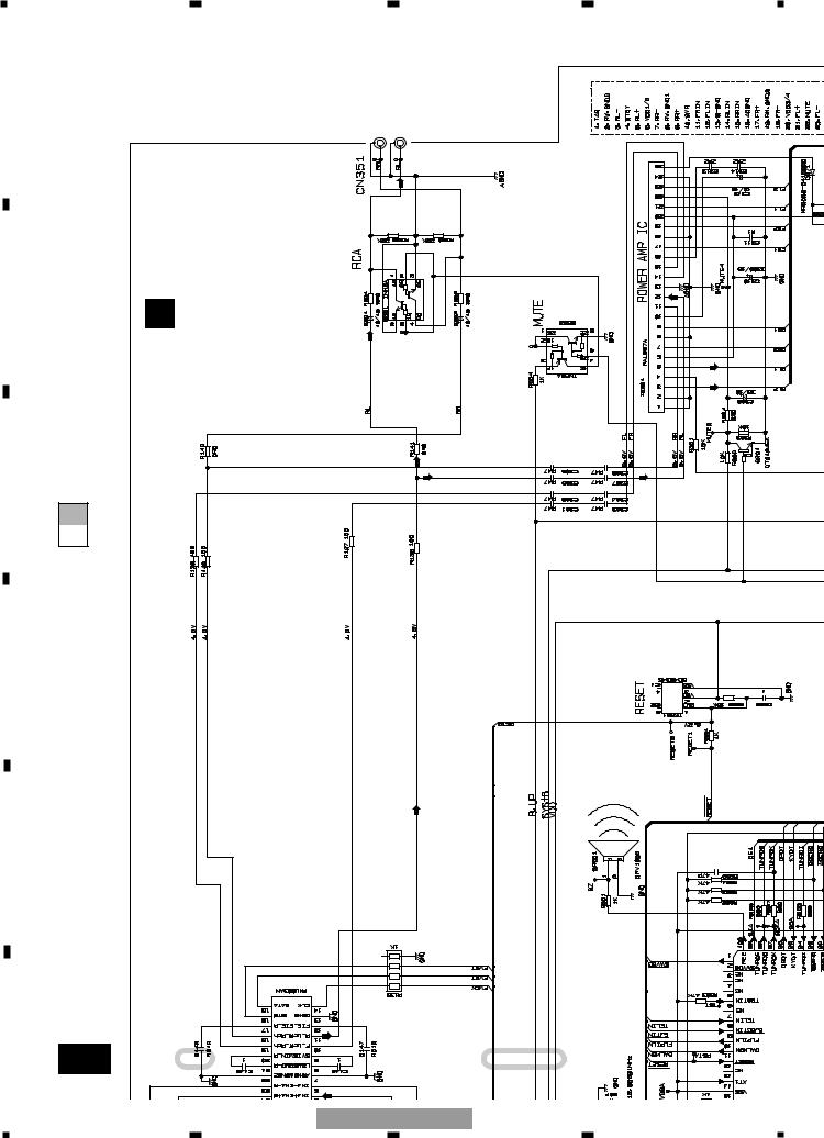
1 |
2 |
3 |
4 |
A |
FM:-6.66dBs |
AM:-6.66dBs BUS:+9.54dBs-IP CD:+9.34dBs |
REAR CHR |
REAR CHL |
|
|
|
|
UNITAMP
TUNER
B
A
C
A-a A-b
D |
|
|
|
|
|
E |
|
|
5.9dBs-FM: 5.9dBs-AM: |
BUS:+10.3dBs |
CD:+10.1dBs |
|
|
|
|
|
|
|
|
|
|
IP- |
|
F |
A-b |
1 |
|
|
2 |
|
|
|
|||
|
20 |
|
DEH-P250/XM/UC |
||
1 |
2 |
3 |
4 |
1C
5
6
3
P250/XM/UC-DEH
7
|
4 |
8 |
A |
21 |
b- |
NOTE :
Symbol indicates a resistor.
No differentiation is made between chip resistors and discrete resistors.
Symbol indicates a capacitor.
No differentiation is made between chip capacitors and discrete capacitors.
A-a A-b
600 H
BACKUP
GND
ACC
B.REM
RL—
FL—
RL+
FL+
RR—
FR—
RR+
FR+
FM:+30dBs
AM:+20dBs
IP-BUS:+36dBs
CD:+36dBs
Decimal points for resistor and capacitor fixed values are expressed as :
2.2 |
← |
2R2 |
|
|
|||
0.022 |
← |
R022 |
|
|
|||
5
6
7
8
F |
|
E |
|
D |
|
C |
|
B |
|
A |
 Loading...