


MUH-GA20VB
SERVICE MANUAL
CONTENTS
1. TECHNICAL CHANGES ····································2
2. PART NAMES AND FUNCTIONS······················6
3. SPECIFICATION·················································6
4. NOISE CRITERIA CURVES·······························7
5. OUTLINES AND DIMENSIONS·························8
6. WIRING DIAGRAM ············································9
7. REFRIGERANT SYSTEM DIAGRAM··············10
8. PERFORMANCE CURVES······························11
9. SERVICE FUNCTIONS ····································22
10. TROUBLESHOOTING ······································22
11. DISASSEMBLY INSTRUCTIONS·····················29
12. PARTS LIST······················································32
Wireless type
Models
MUH-GA20VB -
MUH-GA25VB -
MUH-GA35VB -
E1
E1
E1
No. OB387
HFC
utilized
R410A
SPLIT-TYPE, HEAT PUMP AIR CONDITIONERS
MUH-GA20VB -
MUH-GA25VB -
MUH-GA35VB -
E1
E1
E1
Indication of
model name
NOTE:
•This manual describes technical data of outdoor units.
•As for indoor units MSC-GA20/GA25/GA35VB - , refer to the service manual OB385.
•As for indoor units MSC-CA20/CA25/CA35VB - , refer to the service manual OB393.
E1
E1

TECHNICAL CHANGES
2
1
MUH-A07YV- ➔MUH-GA20VB-
1. Indication of capacity has been changed. (BTU base ➔ kw)
2. Dimension of outdoor unit has been changed. (780W
o540Ho255D ➔ 800Wo550Ho285D)
3. Stop valve cover has been added.
4. Outdoor fan motor has been changed. (RC6V20-AB ➔ RA6V21-AD)
5. Outdoor fan motor capacitor has been changed.
6. Compressor capacitor has been changed.
7. Outdoor heat exchanger has been changed. (L-BEND ➔ FLAT)
MUH-A09YV- ➔MUH-GA25VB-
1. Indication of capacity has been changed. (BTU base ➔ kw)
2. Dimension of outdoor unit has been changed. (780Wo540Ho255D ➔ 800Wo 550Ho285D)
3. Stop valve cover has been added.
4. Outdoor fan motor has been changed. (RA6V33-FB ➔ RA6V33-KB)
5. Outdoor fan motor capacitor has been changed.
6. Compressor capacitor has been changed.
7. Outdoor heat exchanger has been changed. (2 Row ➔ 1 Row)
MUH-A12YV- ➔MUH-GA35VB-
1. Indication of capacity has been changed. (BTU base ➔ kw)
2. Dimension of outdoor unit has been changed. (780Wo540Ho255D ➔ 800Wo 550Ho285D)
3. Stop valve cover has been added.
4. Outdoor fan motor has been changed. (RA6V33-FB ➔ RA6V33-KB)
5. Outdoor fan motor capacitor has been changed.
6. Compressor capacitor has been changed.
7. Size of stop valve (gas) has been changed.(
[12.7 ➔ [9.52)
8. Outdoor heat exchanger has been changed. (2 Row ➔ 1 Row)
E1E1
E1E1
E1E1
3
Refrigeration
oil
Refrigerant
New refrigerant
R410A
HFC-32: HFC-125 (50%:50%)
Pseudo-azeotropic refrigerant
Not included
A1/A1
72.6
-51.4
1.557
64
Non combustible
0
1730
From liquid phase in cylinder
Possible
Incompatible oil
Non
Non
Previous refrigerant
R22
R22 (100%)
Single refrigerant
Included
A1
86.5
-40.8
0.94
44.4
Non combustible
0.055
1700
Gas phase
Possible
Compatible oil
Light yellow
Non
Refrigerant
Composition (Ratio)
Refrigerant handling
Chlorine
Safety group (ASHRAE)
Molecular weight
Boiling point (:)
Steam pressure [25:](Mpa)
Saturated steam density [25:](Kg/K)
Combustibility
ODP w1
GWP w2
Refrigerant charge method
Additional charge on leakage
Kind
Color
Smell
w1:Ozone Destruction Parameter : based on CFC-11
w2 :Global Warmth Parameter : based on CO
2
INFORMATION FOR THE AIR CONDITIONER WITH R410A REFRIGERANT
• This room air conditioner adopts HFC refrigerant (R410A) which never destroys the ozone layer.
• Pay particular attention to the following points, though the basic installation procedure is same as that for R22 conditioners.
1 As R410A has working pressure approximate 1.6 times as high as that of R22, some special tools and piping parts/
materials are required. Refer to the table below.
2 Take sufficient care not to allow water and other contaminations to enter the R410Arefrigerant during storage and
installation, since it is more susceptible to contaminations than R22.
3 For refrigerant piping, use clean, pressure-proof parts/materials specifically designed for R410A. (Refer to 2. Refrigerant
piping.)
4 Composition change may occur in R410A since it is a mixed refrigerant. When charging, charge liquid refrigerant to prevent
composition change.
NOTE : The unit of pressure has been changed to MPa on the international system of units(SI unit system).
The conversion factor is: 1(MPa [Gauge]) =10.2(kgf/
ff
[Gauge])
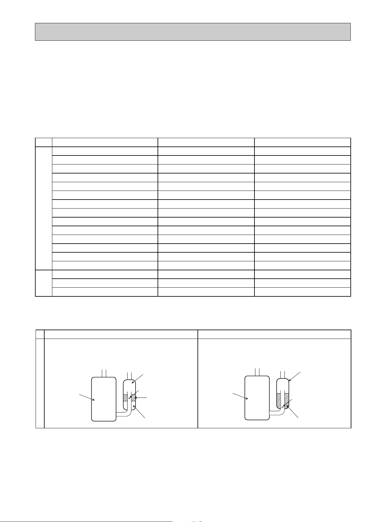
New Specification Current Specification
The incompatible refrigeration oil easily separates from
refrigerant and is in the upper layer inside the suction muffler.
Raising position of the oil back hole enables to back the
refrigeration oil of the upper layer to flow back to the
compressor.
Since refrigerant and refrigerating oil are compatible each,
refrigeration oil goes back to the compressor through the
lower position oil back hole.
Compressor
Suction muffler
Oil back hole
Refrigeration oil
Refrigerant
Compressor
Suction muffler
Oil back hole
Refrigeration oil /Refrigerant
Compressor
4
2.Refrigerant piping
1 Specifications
Use the refrigerant pipes that meet the following specifications.
• Use a copper pipe or a copper-alloy seamless pipe with a thickness of 0.8 mm. Never use any pipe with a thickness less
than 0.8mm, as the pressure resistance is insufficient.
Wall
thickness
Outside diameter
Pipe
mm
For liquid
For gas
6.35
9.52
0.8 mm
0.8 mm
Heat resisting foam plastic
Specific gravity 0.045 Thickness 8 mm
Insulation material
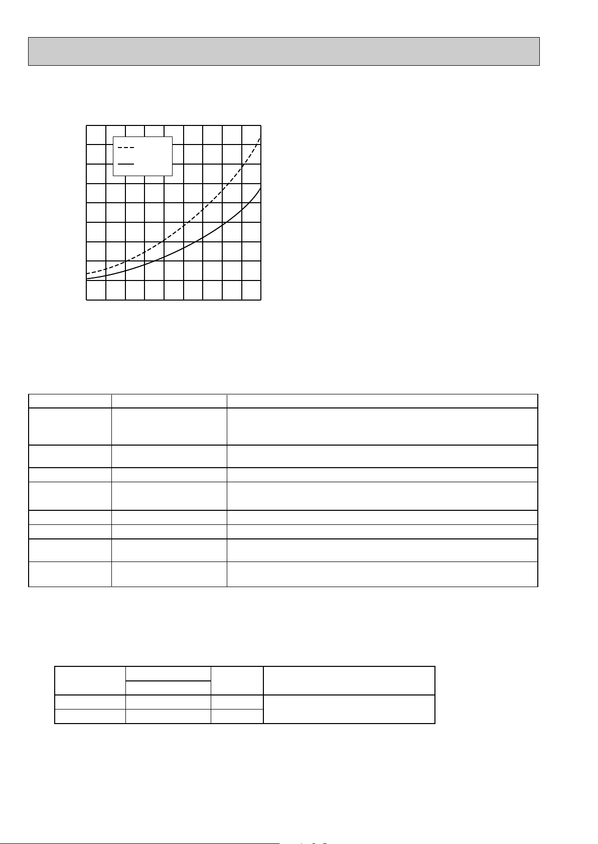
-30 -20 -10 0 10 20
30
40 50 60
-0.5
0.0
0.5
1.0
1.5
2.0
2.5
3.0
3.5
4.0
(MPa [Gauge])
R410A
R22
Conversion chart of refrigerant temperature and pressure
Saturated liquid pressure
(:)
NOTE : The unit of pressure has been changed to MPa on the
international system of units(SI unit system).
The conversion factor is: 1(MPa [Gauge]) =10.2(kgf/
ff
[Gauge])
R410A tools Can R22 tools be used?
Gas leak detector
R410A has high pressures beyond the measurement range of existing
gauges. Port diameters have been changed to prevent any other refrigerant
from being charged into the unit.
Hose material and cap size have been changed to improve the pressure
resistance.
Dedicated for HFC refrigerant.
6.35 mm and 9.52 mm
Description
Clamp bar hole has been enlarged to reinforce the spring strength in the tool.
Provided for flaring work (to be used with R22 flare tool).
Provided to prevent the back flow of oil. This adapter enables you to use
vacuum pumps.
It is difficult to measure R410A with a charging cylinder because the
refrigerant bubbles due to high pressure and high-speed vaporization
No
No
No
Yes
Yes
New
New
New
Gauge manifold
Charge hose
Torque wrench
Flare tool
Flare gauge
Vacuum pump
adapter
Electronic scale for
refrigerant charging
No : Not Substitutable for R410A Yes : Substitutable for R410A
1.Tools dedicated for the air conditioner with R410A refrigerant
The following tools are required for R410A refrigerant. Some R22 tools can be substituted for R410A tools.
The diameter of the service port on the stop valve in outdoor unit has been changed to prevent any other refrigerant being
charged into the unit. Cap size has been changed from 7/16 UNF with 20 threads to 1/2 UNF with 20 threads.
5
R410A
Pipe diameter
mm
6.35
9.52
17
22
Dimension of flare nut
R22
17
22
2 Flaring work and flare nut
Flaring work for R410A pipe differs from that for R22 pipe.
For details of flaring work, refer to Installation manual “FLARING WORK”.
3.Refrigeration oil
Apply the special refrigeration oil (accessories: packed with indoor unit) to the flare and the union seat surfaces.
4.Air purge
• Do not discharge the refrigerant into the atmosphere.
Take care not to discharge refrigerant into the atmosphere during installation, reinstallation, or repairs to the refrigerant
circuit.
• Use the vacuum pump for air purging for the purpose of environmental protection.
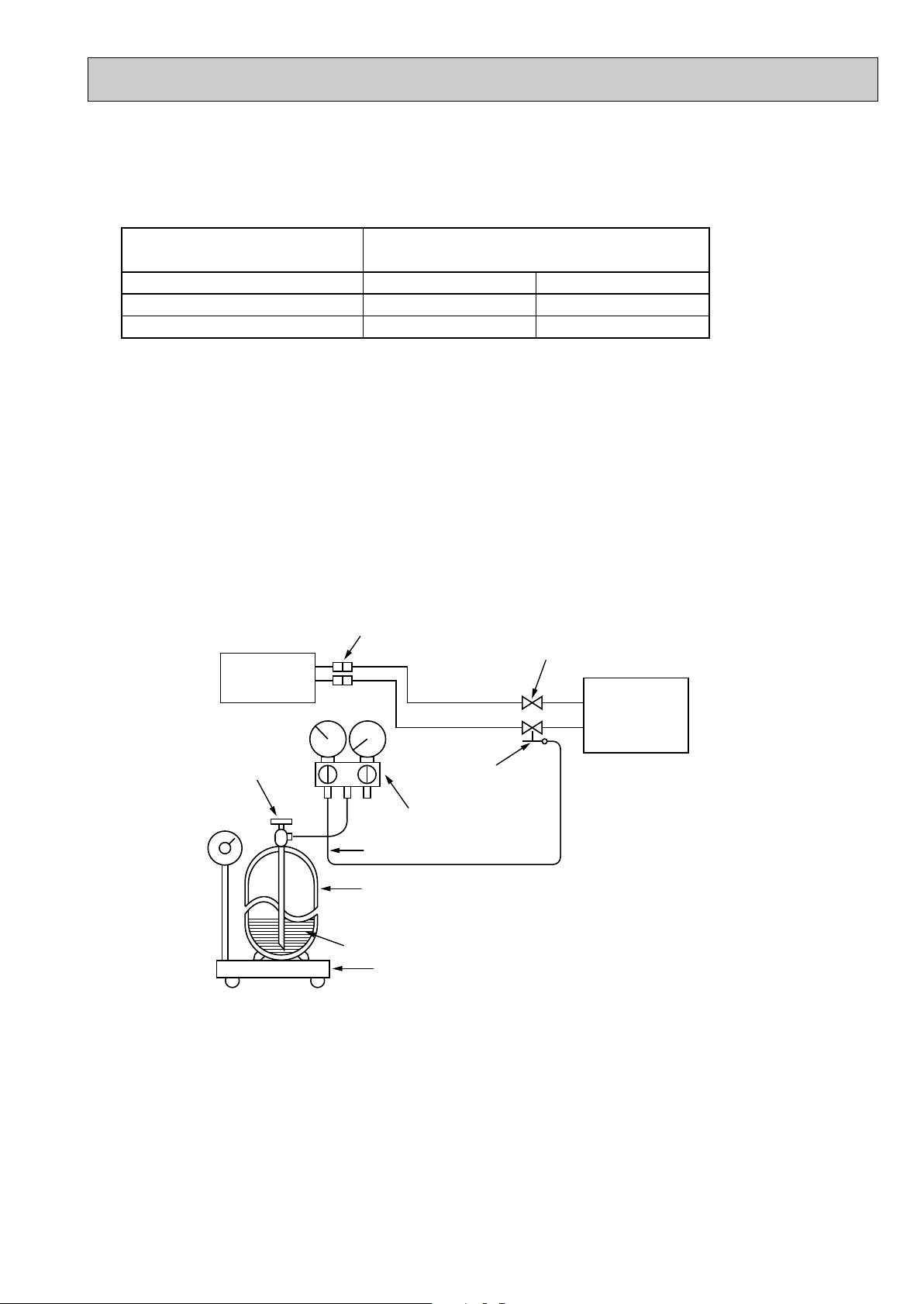
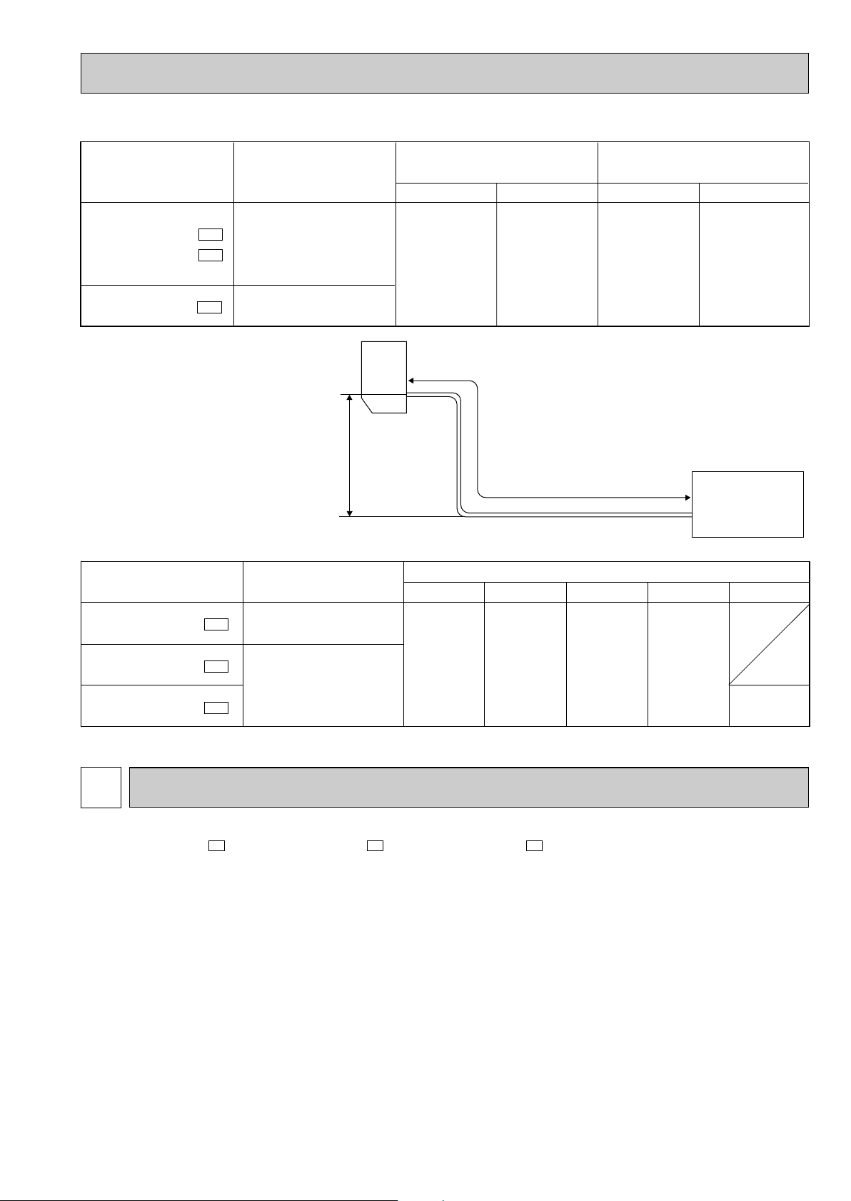
5.Additional charge
For additional charging, charge the refrigerant from liquid phase of the gas cylinder.
If the refrigerant is charged from the gas phase, composition change may occur in the refrigerant inside the cylinder and the
outdoor unit. In this case, ability of the refrigeration cycle decreases or normal operation can be impossible. However,
charging the liquid refrigerant all at once may cause the compressor to be locked. Thus, charge the refrigerant slowly.
Electronic scale for refrigerant charging
Outdoor unit
Refrigerant gas
cylinder
operating valve
Refrigerant gas cylinder
for R410A with siphon
Refrigerant (liquid)
Service port
Gauge manifold
valve (for R410A)
Union
Liquid pipe
Gas pipe
Stop valve
Indoor unit
Charge hose (for R410A)
6
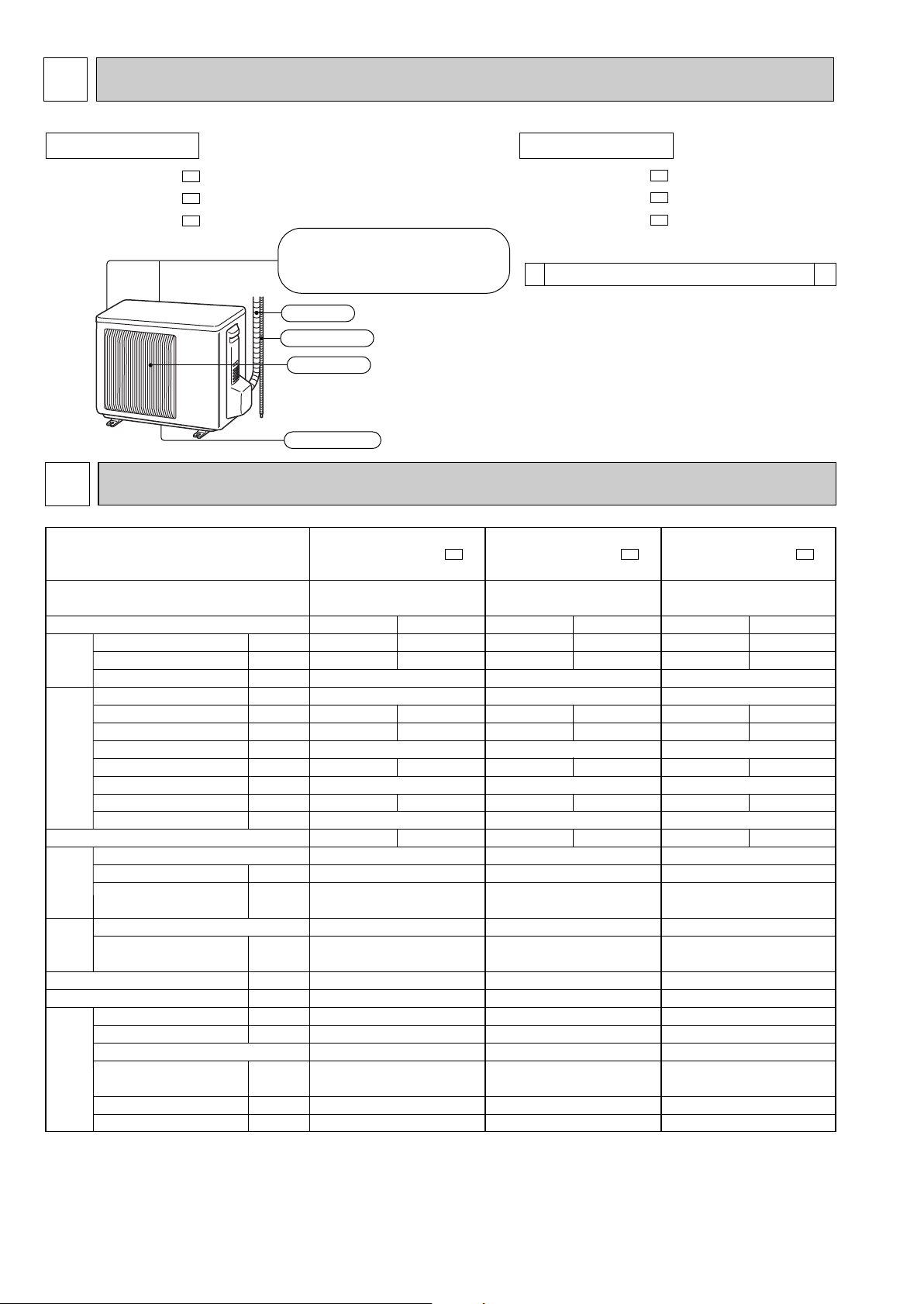
PART NAMES AND FUNCTIONS
2
( )
Air inlet
Air outlet
Drain outlet
Piping
Drain hose
back : MUH-GA20VB
back and side : MUH-GA25VB
MUH-GA35VB
OUTDOOR UNIT
MUH-GA20VB -
MUH-GA25VB -
MUH-GA35VB -
E1
E1
E1
ACCESSORIES
MUH-GA20VB-
MUH-GA25VB-
MUH-GA35VB-
E1
E1
E1
Drain socket
1
<Outdoor unit: MUH type>
1
SPECIFICATION
3
Capacity
Dehumidification
Outdoor air flow
Power outlet
Running current
Power input
Auxiliary heater
Power factor
Starting current
Compressor motor current
Fan motor current
Model
Output
Winding
resistance (at 20:)
Model
Winding
resistance (at 20:)
Dimensions WOHOD
Weight
Sound level
Fan speed
Fan speed regulator
Refrigerant filling
capacity (R410A)
Refrigeration oil (Model)
Thermistor RT61 (at 0:)
kW
R/h
K /h
A
A
W
A(kW)
%
A
A
A
W
"
"
mm
kg
dB
rpm
kg
cc
k"
MUH-GA20VB -
E1
Single phase
230V,50Hz
1800
10
—
21
0.25
RN092VHSHT
600
C-R 3.87
C-S 6.14
RA6V21-AD
WHT-BLK 366
BLK-RED 274
800o550o285
32
47
745
1
0.65
350 (NEO22)
33.18
Cooling
2.3
0.9
3.00
680
99
2.76
3.22
Heating
2.5
—
2.86
655
100
2.62
3.62
MUH-GA25VB -
E1
Single phase
230V,50Hz
1902
10
—
22
0.33
RN104VHSHT
700
C-R 3.40
C-S 4.56
RA6V33-KB
WHT-BLK 215
BLK-RED 307
800o550o285
32
49
855
1
0.80
350 (NEO22)
33.18
Cooling
2.65
1.1
3.43
785
100
3.10
3.23
Heating
3.0
—
3.43
785
100
3.10
3.66
MUH-GA35VB -
E1
Single phase
230V,50Hz
1902
10
—
27
0.33
RN135VHSHT
900
C-R 2.79
C-S 3.36
RA6V33-KB
WHT-BLK 215
BLK-RED 307
800o550o285
35
49
855
1
0.80
620 (NEO22)
33.18
Cooling
3.5
1.7
4.65
1,050
98
4.32
3.21
Heating
3.7
—
4.34
980
98
4.01
3.63
Compressor
Electrical
data
Fan
motor
Special
remarks
Capacity
Coefficient of performance (C.O.P)
Outdoor unit power supply
Function
Outdoor model
NOTE: Test conditions are based on ISO 5151.
Cooling : Indoor DB27°C WB19°C Heating : Indoor DB20°C
Outdoor DB35°C WB24°C Outdoor DB 7°C/WB 6°C
Indoor-Outdoor piping length : 5m
7
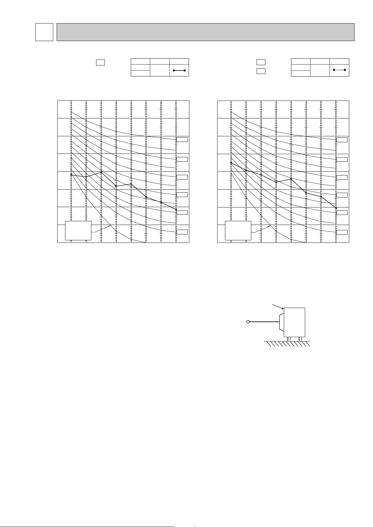
NOISE CRITERIA CURVES
4
90
80
70
60
50
40
30
20
10
63 125 250 500 1000 2000 4000 8000
APPROXIMATE
TERESHOLD OF
HEARING FOR
CONTINUOUS
NOISE
NC-60
NC-50
NC-40
NC-30
NC-20
NC-70
OCTAVE BAND SOUND PRESSURE LEVEL, dB re 0.0002 MICRO BAR
BAND CENTER FREQUENCIES, Hz
Test conditions,
Cooling :DB35: WB24:
Heating :DB 7: WB 6:
MUH-GA25VB- E1
MUH-GA35VB- E1
COOLING
FUNCTION
49
HEATING
SPL(dB
(A)) LINE
OUTDOORUNIT
MICROPHONE
1m
90
80
70
60
50
40
30
20
10
63 125 250 500 1000 2000 4000 8000
APPROXIMATE
TERESHOLD OF
HEARING FOR
CONTINUOUS
NOISE
NC-60
NC-50
NC-40
NC-30
NC-20
NC-70
OCTAVE BAND SOUND PRESSURE LEVEL, dB re 0.0002 MICRO BAR
BAND CENTER FREQUENCIES, Hz
Test conditions,
Cooling :DB35: WB24:
Heating :DB 7: WB 6:
MUH-GA20VB- E1
COOLING
FUNCTION
47
HEATING
SPL(dB
(A)) LINE
8
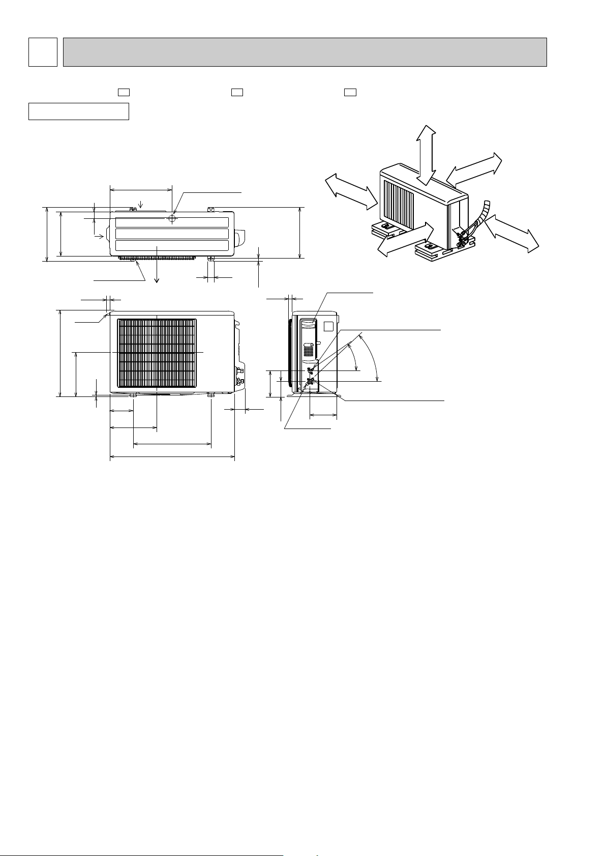
OUTLINES AND DIMENSIONS
5
10
69
800
302.5
500 Bolt pitch for installation
150
22.3
Handle
550
280
164.5
99.5
170.5
23
Service panel
Service port
285
344.5
44
400
Air in
Air out
Air in
17.5
Bolt pitch for
installation
304~325
40
Liquid refrigerant pipe joint
Refrigerant pipe (flared) [6.35
Gas refrigerant pipe joint
Refrigerant pipe (flared) [9.52
43-
35-
2 holes 10X21
(MUH-GA25
/GA35VB)
REQUIRED SPACE
Basically open 100mm or more
without any obstruction in front
and on both sides of the unit.
350mm or more
200mm or more
100mm or more
100mm or more
Open two sides of left,
right, or rear side.
Drain hole [42
Unit: mm
OUTDOOR UNIT
MUH-GA20VB - MUH-GA25VB - MUH-GA35VB -
E1E1E1
9
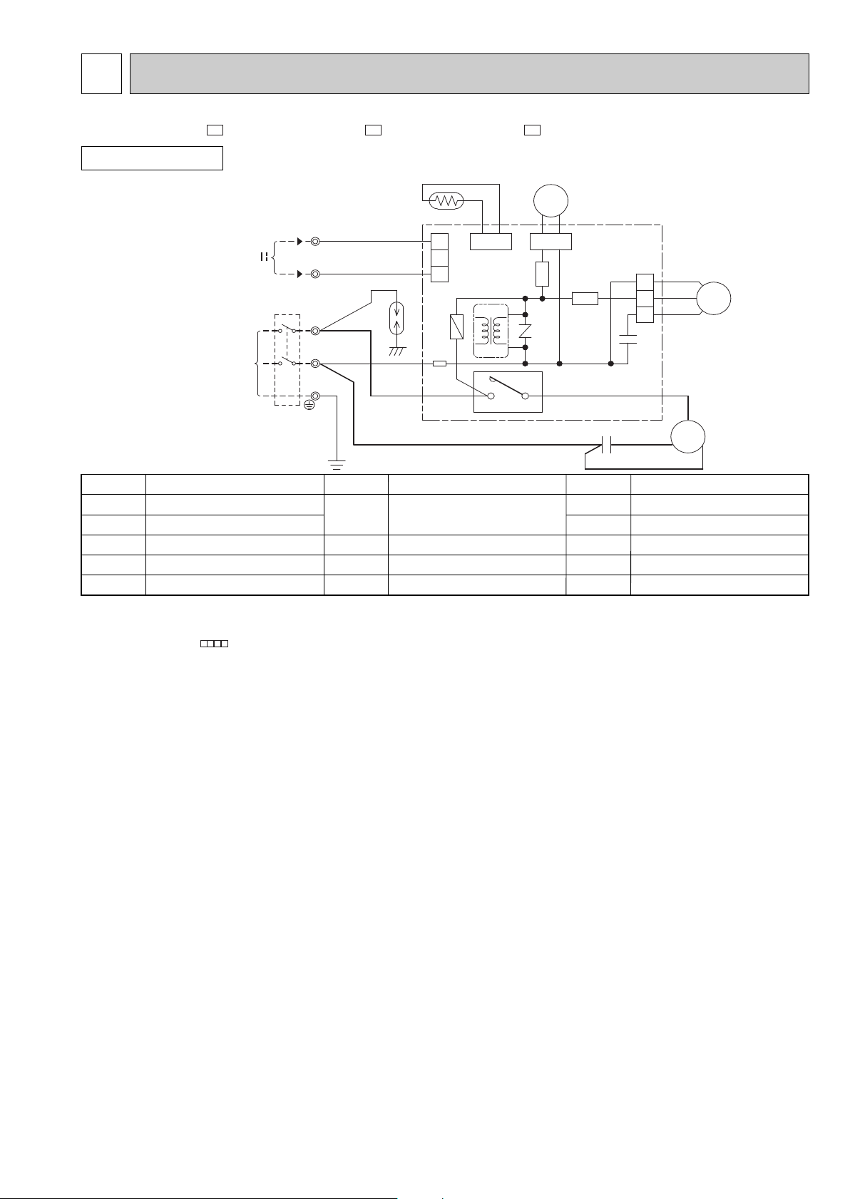
WIRING DIAGRAM
6
MODELS WIRING DIAGRAM
SYMBOL
T61
TB1,TB2
21S4
52C
SYMBOL
MF
NR61
RT61
SR61,SR62
SYMBOL
C1
C65
DSAR
F61
MC
NAME
NAME NAME
COMPRESSOR CAPACITOR
OUTDOOR FAN CAPACITOR
SURGE ABSORBER
FUSE(2A)
COMPRESSOR(INNER PROTECTOR)
VARISTOR
DEFROST THERMISTOR
SOLID STATE RELAY
TRANS FORMER
TERMINAL BLOCK
R.V. COIL
COMPRESSOR CONTACTOR
OUTDOOR FAN MOTOR
(INNER FUSE)
TAB20
PE
N
3
TB2
N
L
TB1
BRN
321
CN711
CN730
BLU
NR61
RT61
21S4
CN661
C65
123
SR61
SR62
CN721
T61
WHT
C
MC
S
R
RED
BLK
C1
F61
BRN
DSAR
CIRCUIT
BREAKER
BLU
POWER SUPPLY
~/N 230V 50Hz
12V
TO INDOOR
UNIT
CONNECTING
RED
BLK
GRN/YLW
3
52C
4
BLK
WHT
RED
MF
OUTDOOR UNIT
NOTE:1. About the indoor side electric wiring refer to the indoor unit electric wiring diagram for servicing.
2. Use copper conductors only. (For field wiring)
3. Symbols below indicate.
/: Terminal block, : Connector
MUH-GA20VB - MUH-GA25VB - MUH-GA35VB -
E1E1E1
10
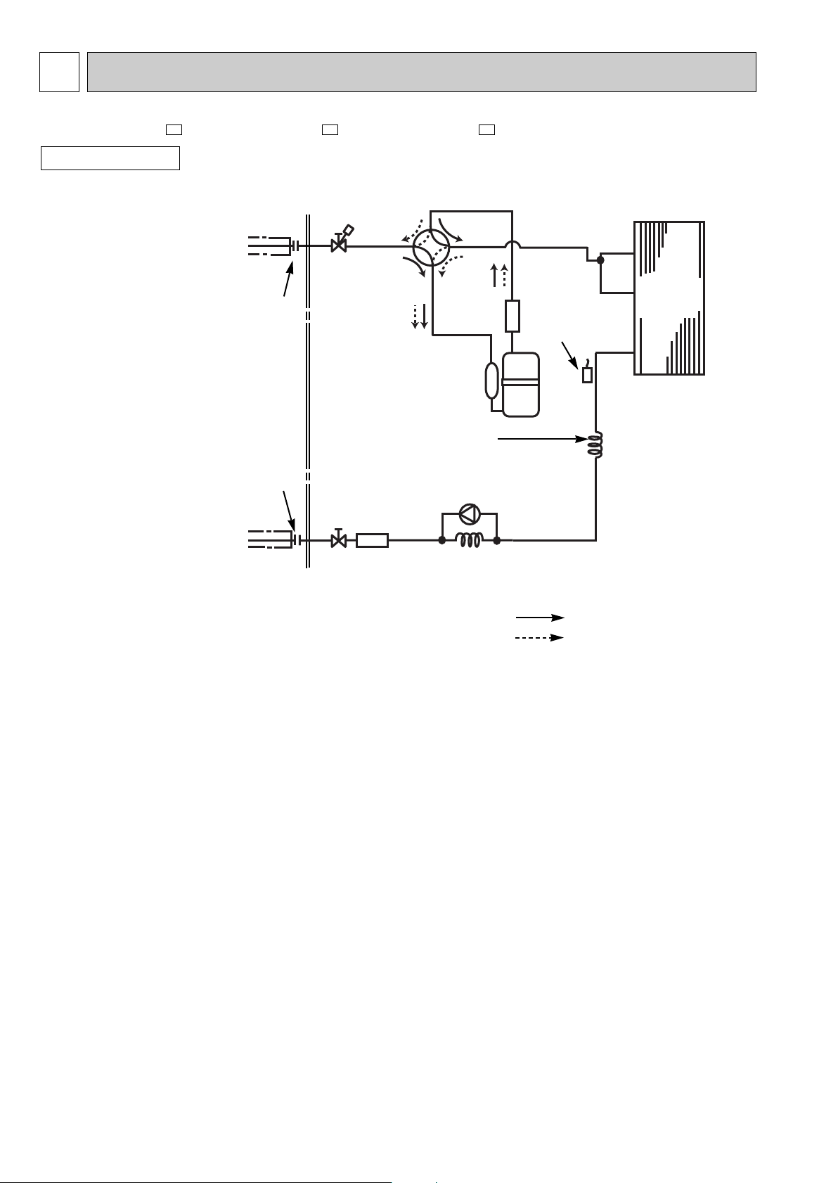
REFRIGERANT SYSTEM DIAGRAM
7
OUTDOOR UNIT
(with heat insulator)
Refrigerant pipe [ 9.52
4-way valve
Defrost
thermistor
RT61
Muffler
Outdoor
heat
exchanger
Capillary tube
[3.0x[1.4x700 (MUH-GA20VB)
[3.0x[1.4x1000(MUH-GA25VB)
[3.0x[1.4x500 (MUH-GA35VB)
Capillary tube
[3.0x[1.4x500 (MUH-GA20VB)
[3.0x[1.4x600 (MUH-GA25VB)
[3.0x[1.4x300 (MUH-GA35VB)
Check valve
Strainer
#100
Refrigerant pipe [6.35
(with heat insulator)
Refrigerant flow in cooling
Refrigerant flow in heating
Unit:mm
Stop valve
(with service
port)
R.V. coil
heating ON
cooling OFF
Flared connection
Flared connection
Compressor
Stop valve
MUH-GA20VB - MUH-GA25VB - MUH-GA35VB -
E1E1E1
11
Piping size O.D : mm Length of connecting pipe : m
Model
Refrigerant piping
Max. length : m
A
20
25
Indoor unit
Gas 0.43
Liquid 0.5
Liquid
6.35
Gas
9.52
Outdoor unit
Gas 0
Liquid 0
MUH-GA20VB - E1
MUH-GA25VB - E1
MUH-GA35VB - E1
Indoor
unit
w Max. Height
difference 10m
Height difference should be within
10m regardless of which unit,
indoor or outdoor position is high.
Outdoor unit
Refrigerant Piping
Max.length
A
Model
Refrigerant piping length (one way)
7m
0
10m
60
15m
160
20m
260
MUH-GA20VB - E1
MUH-GA25VB - E1
MUH-GA35VB - E1
Calculation : Xg = 20g/m x (A-7)m
25m
360
Outdoor unit precharged
650
800
MAX. HEIGHT DIFFERENCE
ADDITIONAL REFRIGERANT CHARGE(R410A : g)
MAX. REFRIGERANT PIPING LENGTH
PERFORMANCE CURVES
8
The standard data contained in these specifications apply only to the operation of the air conditioner under normal conditions,
since operating conditions vary according to the areas where these units are installed. The following information has been pro-
vided to clarify the operating characteristics of the air conditioner under the conditions indicated by the performance curve.
(1) GUARANTEED VOLTAGE
198~264V
(2) AIR FLOW
Air flow should be set at MAX.
(3) MAIN READINGS
(1) Indoor intake air wet-bulb temperature : °CWB
(2) Indoor outlet air wet-bulb temperature : °CWB
(3) Outdoor intake air dry-bulb temperature : °CDB
(4) Total input: W
(5) Indoor intake air dry-bulb temperature : °CDB
(6) Outdoor intake air wet-bulb temperature : °CWB
(7) Total input : W
Indoor air wet/dry-bulb temperature difference on the left side of the chart on page 10 shows the difference between the
indoor intake air wet/dry-bulb temperature and the indoor outlet air wet/dry-bulb temperature for your reference at service.
}
}
Cooling
Heating
MUH-GA20VB - MUH-GA25VB - MUH-GA35VB -
E1E1E1
 Loading...