


IMPORTANT
The lightning flash with arrowhead symbol, within an equilateral triangle, is intended to alert the user to the presence of uninsulated "dangerous voltage" within the product's enclosure that may be of sufficient magnitude to constitute a risk of electric shock to persons.
CAUTION
RISK OF ELECTRIC SHOCK
DO NOT OPEN
CAUTION:
TO PREVENT THE RISK OF ELECTRIC SHOCK, DO NOT REMOVE COVER (OR BACK). NO USERSERVICEABLE PARTS INSIDE. REFER SERVICING TO QUALIFIED SERVICE PERSONNEL.
The exclamation point within an equilateral triangle is intended to alert the user to the presence of important operating and maintenance (servicing) instructions in the literature accompanying the appliance.
D3-4-2-1-1_En-A
1)Read these instructions.
2)Keep these instructions.
3)Heed all warnings.
4)Follow all instructions.
5)Do not use this apparatus near water.
6)Clean only with dry cloth.
7)Do not block any ventilation openings. Install in accordance with the manufacturer’s instructions.
8)Do not install near any heat sources such as radiators, heat registers, stoves, or other apparatus (including amplifiers) that produce heat.
9)Do not defeat the safety purpose of the polarized or grounding-type plug. A polarized plug has two blades with one wider than the other. A grounding type plug has two blades and a third grounding prong. The wide blade or the third prong are provided for your safety. If the provided plug does not fit into your outlet, consult an electrician for replacement of the obsolete outlet.
10)Protect the power cord from being walked on or pinched particularly at plugs, convenience receptacles, and the point where they exit from the apparatus.
11)Only use attachments/accessories specified by the manufacturer.
12)Use only with the cart, stand, tripod, bracket, or table specified by the manufacturer, or sold with the apparatus. When a cart is used, use caution when moving the cart/apparatus combination to avoid injury from tip-over.
13)Unplug this apparatus during lightning storms or when unused for long periods of time.
14)Refer all servicing to qualified service personnel.
Servicing is required when the apparatus has been damaged in any way, such as power-supply cord or plug is damaged, liquid has been spilled or objects have fallen into the apparatus, the apparatus has been exposed to rain or moisture, does not operate normally, or has been dropped.
IMPORTANT NOTICE – THE SERIAL NUMBER FOR THIS EQUIPMENT IS LOCATED IN THE REAR. PLEASE WRITE THIS SERIAL NUMBER ON YOUR ENCLOSED WARRANTY CARD AND KEEP IN A SECURE AREA. THIS IS FOR YOUR SECURITY.
WARNING: Handling the cord on this product or cords associated with accessories sold with the product will expose you to chemicals listed on proposition 65 known to the State of California and other governmental entities to cause cancer and birth defect or other
reproductive harm.
Wash hands after handling
D36-P4-A_En

TABLE OF CONTENTS
Congratulations on purchasing a Pioneer Elite KURO monitor.
At Pioneer, everything we do is designed to alter perceptions, to shatter expectations, to change the way people feel about sight and sound.
This exclusive series of Elite KURO monitors does just that. The result of a special limited run created for the entertainment purist, this monitor was designed to excel under the most demanding situations, to be fully customizable to the most particular tastes and to transcend the ordinary.
We are proud to incorporate this philosophy of exceptional quality, state-of-the-art design and meticulous engineering to make the Elite KURO monitor one of the finest in the world and immerse you into one of the best entertainment experiences possible.
Please spend some time reading through this owner’s guide and manual to learn about the many features and benefits that make this Elite KURO monitor unique. We hope you enjoy the experience of owning an Elite KURO and invite you to enter a new world of seeing and hearing like never before.
TABLE OF CONTENTS
1 Introduction to the Flat Panel Displays.................................................................................................. |
6 |
|
1.1 |
Flat Panel Display Shipment Checklist ........................................................................................................................... |
6 |
1.2 |
Control Options: Get to Know Your Flat Panel Display.................................................................................................. |
7 |
|
1.2.1 Control Buttons and More on the Flat Panel Display............................................................................................ |
7 |
|
1.2.2 Operating the Remote Control ............................................................................................................................... |
8 |
|
1.2.3 Buttons on the Remote Control ............................................................................................................................ |
10 |
2 Install Your Flat Panel Display .............................................................................................................. |
12 |
|
2.1 |
Use the Optional Table Top Stand (Stand) or Equivalent Items.................................................................................. |
12 |
2.2 |
Use the Optional Brackets or Equivalent Items ........................................................................................................... |
13 |
|
2.2.1 Check the Location for Suitability ......................................................................................................................... |
14 |
|
2.2.2 Lift and/or Move Your Panel (the How To’s)......................................................................................................... |
14 |
|
2.2.3 Mount the Flat Panel Display ................................................................................................................................ |
15 |
2.3 |
Connect to Other Devices (DVR, Receiver, BDR, etc.) ................................................................................................ |
17 |
2.4 |
Connect the Power Cord to the Panel........................................................................................................................... |
19 |
2.5 |
Route then Bundle the Power Cord and Cables .......................................................................................................... |
19 |
3 Basic Operations..................................................................................................................................... |
21 |
|
3.1 |
Turn the Flat Panel Display ON / OFF ........................................................................................................................... |
21 |
3.2 |
Program Your Flat Panel Display................................................................................................................................... |
22 |
|
3.2.1 Choose an Input Source ........................................................................................................................................ |
22 |
|
3.2.2 Explore the Home Menu ........................................................................................................................................ |
22 |
|
3.2.3 Use the Simplified User Menu .............................................................................................................................. |
23 |
|
3.2.4 Assign a Language................................................................................................................................................. |
24 |
4 Basic Picture Adjustment....................................................................................................................... |
25 |
|
4.1 Adjust the Picture Quality .............................................................................................................................................. |
25 |
|
4.1.1 |
Adjust the Picture for Your Room Lighting .......................................................................................................... |
25 |
4.1.2 |
General Picture (Video) Adjustment..................................................................................................................... |
25 |
4.1.3 Compare Images When Adjusting the Picture.................................................................................................... |
27 |
|
4.2 Smart Starts for New Owners ........................................................................................................................................ |
28 |
|
4.2.1 |
Extend Your Panel Life ........................................................................................................................................... |
28 |
4.2.2 |
Adjust the Power Indicator Brightness ................................................................................................................ |
28 |
4.2.3 |
Set Input Priority..................................................................................................................................................... |
28 |
4.2.4 Turn On the Image Orbiter .................................................................................................................................... |
29 |
|
4.2.5 |
Trigger the Screen-Saving Video Pattern Periodically ........................................................................................ |
29 |
4.2.6 Activate Energy Save to Reduce Power Usage.................................................................................................... |
29 |
|
4.2.7 Turn On the Sleep Timer........................................................................................................................................ |
30 |
|
3
En

TABLE OF CONTENTS
5 Additional Picture Adjustment Options............................................................................................... |
31 |
||
5.1 |
Choose an AV Option (Video, Game, etc.)..................................................................................................................... |
31 |
|
|
5.1.1 AV Source through the Remote Control............................................................................................................... |
31 |
|
|
5.1.2 Choose an AV Source through the Home Menu ................................................................................................. |
32 |
|
|
5.1.3 Choose a PC Source............................................................................................................................................... |
32 |
|
|
5.1.4 Set the Panel to Recognize a Game Console....................................................................................................... |
32 |
|
5.2 |
Adjust Specific Picture Elements .................................................................................................................................. |
33 |
|
|
5.2.1 Choose a Screen Size (Automatically or Manually)............................................................................................. |
33 |
|
|
5.2.2 Correct the Picture for an AV or PC Source ......................................................................................................... |
35 |
|
5.3 |
Assign Advanced Picture Functions ............................................................................................................................. |
36 |
|
|
5.3.1 Adjust for Screen Masking (black bars on sides) ................................................................................................ |
36 |
|
|
5.3.2 Select a Color Temperature Level.......................................................................................................................... |
37 |
|
|
5.3.3 Adjust the Image Gradation Characteristics (Gamma)....................................................................................... |
38 |
|
|
5.3.4 Select a PureCinema Level for High Quality Image............................................................................................. |
38 |
|
|
5.3.5 |
Select an Intelligent Mode Option......................................................................................................................... |
39 |
|
5.3.6 |
Select the Picture Detail Options.......................................................................................................................... |
40 |
|
5.3.7 Use CTI and Color Space ....................................................................................................................................... |
40 |
|
|
5.3.8 Use the Color Management................................................................................................................................... |
41 |
|
|
5.3.9 Reduce Noise from the Image............................................................................................................................... |
41 |
|
|
5.3.10 |
Adjust Color Signals............................................................................................................................................. |
42 |
5.4 |
View in Multi-Screen ....................................................................................................................................................... |
43 |
|
|
5.4.1 |
Split / Swap / Shift the Screen............................................................................................................................... |
43 |
|
5.4.2 Turn the Small Screen On/Off ............................................................................................................................... |
44 |
|
5.5 |
Freeze the Picture ........................................................................................................................................................... |
44 |
|
5.6 |
Manage the Power .......................................................................................................................................................... |
45 |
|
6 Use Other Equipment With Your Flat Panel Display ........................................................................... |
46 |
||
6.1 |
Program the Remote Control to Operate Other Equipment........................................................................................ |
46 |
|
|
6.1.1 Use the Learning Function .................................................................................................................................... |
46 |
|
|
6.1.2 Assign a Manufacturing Code to the Remote Control ........................................................................................ |
47 |
|
|
6.1.3 Issue a Library Search for a Manufacturer Code ................................................................................................. |
47 |
|
|
6.1.4 Clear Added Manufacturer Codes from the Remote Control ............................................................................. |
48 |
|
|
6.1.5 |
Control a Pioneer Receiver .................................................................................................................................... |
48 |
|
6.1.6 |
Control a Cable (CBL) or Satellite (SAT) System.................................................................................................. |
49 |
|
6.1.7 Control a Video Cassette Recorder (VCR) ............................................................................................................ |
50 |
|
|
6.1.8 Control a DVD Player/DVR Recorder/BD Player.................................................................................................. |
51 |
|
6.2 |
Apply Settings for Other Equipment.............................................................................................................................. |
52 |
|
|
6.2.1 Apply Settings for an AV System........................................................................................................................... |
52 |
|
|
6.2.2 |
Apply Settings for a PC .......................................................................................................................................... |
53 |
6.3 |
Use HDMI Inputs............................................................................................................................................................. |
54 |
|
|
6.3.1 Enter an HDMI Input Name................................................................................................................................... |
54 |
|
|
6.3.2 Specify the HDMI Input Type ................................................................................................................................. |
55 |
|
|
6.3.3 Specify a Digital HDMI Signal Type ...................................................................................................................... |
55 |
|
6.4 |
Control Equipment with the Panel’s Remote Through HDMI ..................................................................................... |
56 |
|
|
6.4.1 Control an AV System............................................................................................................................................. |
58 |
|
|
6.4.2 Control a Recorder ................................................................................................................................................. |
59 |
|
|
6.4.3 |
Control a Player....................................................................................................................................................... |
59 |
|
6.4.4 Add an AV Amp or a BD Player............................................................................................................................. |
60 |
|
6.5 |
Specific KURO LINK Commands .................................................................................................................................. |
61 |
|
|
6.5.1 Play Source Sound Using an HDMI Command................................................................................................... |
61 |
|
|
6.5.2 Turn OFF the Power With an HDMI Command ................................................................................................... |
61 |
|
|
6.5.3 Turn ON the Power With an HDMI Command..................................................................................................... |
61 |
|
|
6.5.4 |
Test the Power Control (On/Off) ............................................................................................................................ |
62 |
6.6 |
Connect a Game Console or Camcorder ...................................................................................................................... |
62 |
|
6.7 |
Use the IR REPEATER OUT ............................................................................................................................................ |
62 |
|
6.8 |
Connect to a Network ..................................................................................................................................................... |
63 |
|
|
6.8.1 |
IP Control Setting ................................................................................................................................................... |
64 |
|
6.8.2 Use the Web Control System................................................................................................................................. |
65 |
|
4
En

TABLE OF CONTENTS
6.9 |
Assign a Serial Number ................................................................................................................................................. |
69 |
|
|
6.9.1 Assign an ID Number ............................................................................................................................................ |
69 |
|
|
6.9.2 Assign a Baud Rate................................................................................................................................................ |
70 |
|
6.10 Select the Integrator Mode .......................................................................................................................................... |
70 |
||
|
6.10.1 Explore the Integrator Mode Menus ................................................................................................................... |
71 |
|
7 Helpful Information............................................................................................................................... |
75 |
||
7.1 |
Frequently Asked Questions (FAQs) ............................................................................................................................. |
75 |
|
7.2 |
Cleaning Methods........................................................................................................................................................... |
76 |
|
7.3 |
Troubleshooting & Service Information......................................................................................................................... |
77 |
|
8 Cautions and Warnings.......................................................................................................................... |
80 |
||
8.1 |
Installation Details .......................................................................................................................................................... |
80 |
|
8.2 |
Physical Location & Temperature Considerations ....................................................................................................... |
80 |
|
8.3 |
Usage Guidelines ............................................................................................................................................................ |
80 |
|
8.4 |
Signal Interference or Noise .......................................................................................................................................... |
81 |
|
8.5 |
Phosphor Properties....................................................................................................................................................... |
81 |
|
8.6 |
Image Information Including Retention & After-Image Lag ........................................................................................ |
81 |
|
8.7 |
Prevent Burning .............................................................................................................................................................. |
82 |
|
8.8 |
Safety Precautions.......................................................................................................................................................... |
83 |
|
8.9 |
Legal Notices................................................................................................................................................................... |
83 |
|
|
8.9.1 |
Safety....................................................................................................................................................................... |
83 |
|
8.9.2 |
Radio Interference.................................................................................................................................................. |
84 |
9 Appendix ................................................................................................................................................ |
85 |
||
9.1 |
Manufacturer Codes to Program into the Remote Control......................................................................................... |
85 |
|
|
9.1.1 |
Cable........................................................................................................................................................................ |
85 |
|
9.1.2 |
Satellite.................................................................................................................................................................... |
86 |
|
9.1.3 VCR .......................................................................................................................................................................... |
88 |
|
|
9.1.4 |
BDP (Blu-ray) .......................................................................................................................................................... |
91 |
|
9.1.5 DVD-R...................................................................................................................................................................... |
92 |
|
|
9.1.6 DVD.......................................................................................................................................................................... |
93 |
|
|
9.1.7 LD............................................................................................................................................................................. |
95 |
|
9.2 |
Video/PC Signals (HDMI/DVI/Component/min D-Sub/Composite) ........................................................................... |
96 |
|
|
9.2.1 |
INPUT 1 (Video Signals)......................................................................................................................................... |
96 |
|
9.2.2 INPUT 2 (Component)/INPUT 3 (D-Sub) - Video Signals (Analog)..................................................................... |
96 |
|
|
9.2.3 INPUT 4 (DVI)/INPUT 5 through 8 (HDMI) - Video Signals (Digital)................................................................... |
97 |
|
|
9.2.4 INPUT 3 (D-Sub) - PC Signals (Analog) ................................................................................................................ |
98 |
|
|
9.2.5 INPUT 4 (DVI)/INPUT 5 through 8 (HDMI) - PC Signals (Digital) ....................................................................... |
99 |
|
9.3 |
Specifications................................................................................................................................................................ |
101 |
|
9.4 |
Trademarks.................................................................................................................................................................... |
101 |
|
9.5 |
Glossary ......................................................................................................................................................................... |
102 |
|
9.6 |
Index............................................................................................................................................................................... |
104 |
|
5
En
01 |
Introduction to the Flat Panel Displays |
1 Introduction to the Flat Panel Displays
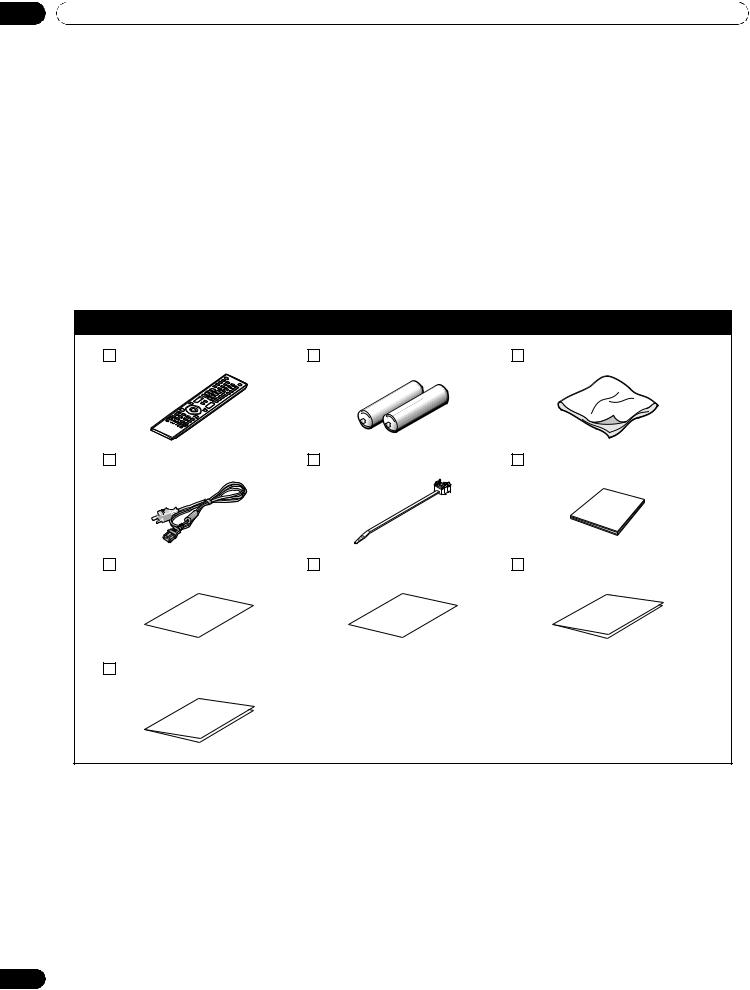
The Pioneer Flat Panel Display models include the 60-inch PRO-141FD and the 50-inch PRO-101FD (screen sizes measured diagonally). Below is a list of all accessories shipped with your panel. If an item is missing, please contact your dealer or our Service organization immediately. Service contact information is listed on the back of this manual.
1.1Flat Panel Display Shipment Checklist
In addition to the flat panel display, there are several accessories included to make installation quick and easy. Please check contents before discarding or allowing your installer to discard any packing material.
Identify the accessories from the appropriate list below.
You will need a Philips screwdriver if removing or attaching the stand.
Shipped with both models
Remote Control |
Batteries for Remote (2) |
Cleaning Cloth |
Power Cord (2 m/6.6 feet) |
Cable Clamps (4) |
Operating Instructions |
Certificate of Authenticity |
Certificate Glossary |
Warranty Card |
Specifications Sheet
6
En
Introduction to the Flat Panel Displays |
01 |
1.2Control Options: Get to Know Your Flat Panel Display
You can operate your flat panel display from the panel buttons or with the remote control. The following sections provide button locations/operations for the panel and the remote control.
1.2.1Control Buttons and More on the Flat Panel Display
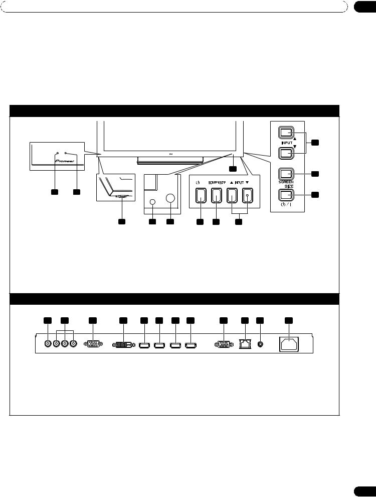
Your flat panel display has buttons, indicators, and sensors on the lower front bezel with more buttons on the rear panel. Refer to the drawings below for specific locations and functions. Or, to identify back ports and terminals only, check the terminal position sheet located near the panel’s terminal compartment.
PRO-141FD/PRO-101FD: Face of Panel
|
|
|
|
|
|
|
|
|
|
|
|
8 |
|
|
|
|
|
|
|
|
|
|
|
|
7 |
|
1 |
|
2 |
|
|
|
|
|
|
|
|
6 |
|
|
|
|
|
|
|
|
|
|
|
|
|
|
|
|
|
3 |
|
4 |
5 |
6 |
7 |
8 |
|
|
|
|
|
|
|
|
|
PRO-101FD |
|
|
|
PRO-141FD |
|
|
|
|
|
|
|
|
(Bottom of the rear panel) |
|
(Right side) |
|||
1 |
- Power On indicator |
|
|
|
6 |
- STANDBY/ON button |
|
|
||||
2 |
- STANDBY indicator |
|
|
|
7 |
- SCREEN SIZE button |
|
|
||||
3 |
- Power On ( ) button |
|
|
|
8 |
- INPUT buttons |
|
|
|
|||
4 |
- Room Light sensor |
|
|
|
9 |
- Bezel (some call it the front frame) |
||||||
5 |
- Remote Control sensor |
|
|
|
|
|
|
|
|
|
||
|
|
|
|
|
|
Back of the Panel |
|
|
|
|
||
(upper bank) |
|
|
|
|
|
|
|
|
|
|
|
|
|
1 |
2 |
3 |
4 |
5 |
6 |
7 |
8 |
9 |
10 |
11 |
12 |
(from left to right) |
|
|
|
1 |
- INPUT 1 terminal (Video) |
7 |
- INPUT 7 terminal (HDMI) |
2 |
- INPUT 2 terminals (Component, Y, CB/PB, CR/PR) |
8 |
- INPUT 8 terminal (HDMI) |
3 |
- INPUT 3 terminal (Analog RGB) |
9 |
- RS-232C terminal (for factory use) |
4 |
- INPUT 4 terminal (DVI-D) |
10 |
- LAN terminal |
5 |
- INPUT 5 terminal (HDMI) |
11 |
- IR REPEATER OUT terminal |
6 |
- INPUT 6 terminal (HDMI) |
12 |
- AC In terminal |
Terminals on the rear panel are common to both models.
7
En
01 |
Introduction to the Flat Panel Displays |
1.2.2Operating the Remote Control
The remote control for the flat panel display is a powerful tool. This section provides a brief introduction to your remote control while later sections explore more advanced operations.
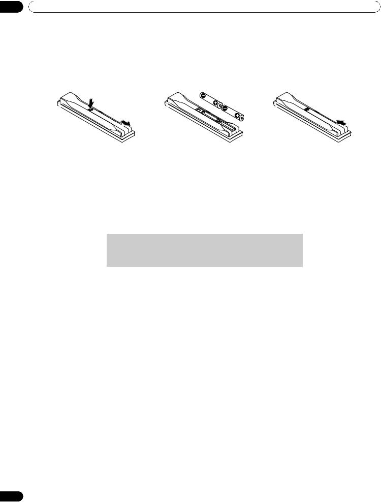
Insert the Batteries into the Remote Control
To open, push and slide the battery cover in the direction of the arrows.
Load the supplied two AA size batteries by the negative polarity (–) ends first.
The batteries supplied with this product may have a shorter life expectancy due to storage conditions. If the remote control seems to be failing or is weak, replace the provided batteries with new alkaline batteries. Never mix old and new batteries. Mixing old and new batteries can shorten the life of new batteries or cause
chemical leaks in old batteries. Also, mixing different types or brands of batteries can cause issues as batteries brands have slightly different characteristics.
Note: If the flat panel display’s remote control is not needed for an extended length of time, remove the batteries.
When disposing of used batteries, please comply with governmental regulations or environmental public institution’s rules that apply in your country/area.
8
En
Introduction to the Flat Panel Displays |
01 |
Remote Control Issues
There are a small number of issues that can affect your remote control but the most common is weak batteries. Weak batteries in the remote control can cause communication to fail or only operate sporadically. In this situation, try moving closer to the panel and attempt to control the panel with the remote. If the panel responds, change the batteries. If moving closer has no effect on the panel, check the surroundings for objects that might be blocking the signal. Also consider other equipment with remote controls that are in the area around the panel. Objects and other IR signals can disrupt the remote. For more help with your remote control, refer to “7.1 Frequently Asked Questions (FAQs)”.
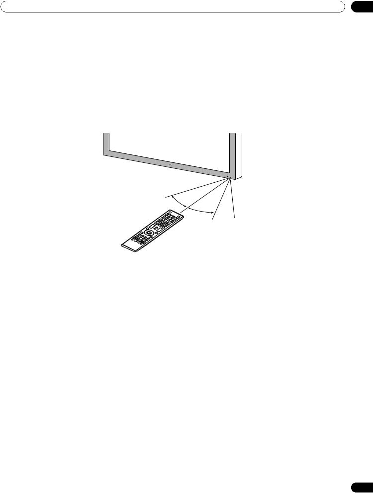
Operating Range for the Remote Control
To control the flat panel display, point the remote towards the sensor on the panel’s bottom right corner. For easy operation, keep the distance between the remote control and the sensor less than 7 m (23 feet) and at an angle of less than 30 degrees.
30º |
7 m |
(23 feet) |
|
|
30º |
Sensor
The remote control may not work properly if the sensor is in direct sunlight or very bright lighting. If your viewing room is naturally bright, change the position of the panel or physically use the remote control closer to the panel’s sensor.
Note: If the remote control is left sitting in direct sunlight or under a very strong light, the case could warp or deform.
9
En
01 |
Introduction to the Flat Panel Displays |
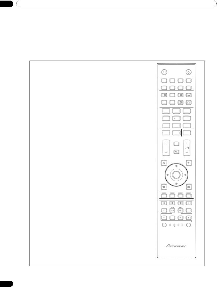
1.2.3Buttons on the Remote Control
Except for a few options, commands available through the buttons on the flat panel display are duplicated on the remote control. The remote control can be programmed to control other equipment such as a DVD Player, Surround Sound system, etc. A later section entitled “6. Use Other Equipment With Your Flat Panel Display” explains how to use the remote to control other equipment.
This section identifies and describes the buttons on the remote control.
Remote: Left side buttons (top to bottom, left to right)
MONITOR : |
1 |
MONITOR |
|
|
|
|
|
Turn On or place panel in Standby |
|
|
|
|
|
|
|
|
1 |
|
|
|
|
|
|
INPUT: |
2 |
INPUT |
|
|
|
||
|
|
|
|
||||
1 |
2 |
3 |
|
|
4 |
||
Select a source (INPUT 1 thru INPUT 8) |
|
|
|
||||
|
|
2 |
|
|
|
||
|
|
|
|
|
|
||
SPLIT: |
3 |
5 |
6 |
7 |
|
|
8 |
SPLIT |
SUB |
SWAP |
|
PIP |
|||
|
|
INPUT |
|
SHIFT |
|||
Cycle view thru single-screen, 2-screen, |
|
3 |
4 |
|
|
|
|
picture-in-picture |
|
AV |
AUTO |
FREEZE |
|
SCREEN |
|
|
SELECTION |
SETUP |
|
SIZE |
|||
SUB INPUT: |
4 |
5 |
6 |
|
|
|
|
|
|
|
|
|
|
||
Switch inputs for sub screens when viewing in multi-screen |
|
1 |
2 |
|
|
3 |
|
AV SELECTION: |
5 |
4 |
7 |
|
6 |
||
|
|
5 |
|
|
|||
Select audio/video settings |
|
7 |
8 |
|
|
9 |
|
AV Source: OPTIMUM, STANDARD, DYNAMIC, MOVIE, |
|
|
|
||||
|
8 |
|
|
|
|
|
|
PURE, SPORT, GAME, USER |
|
0 |
|
|
ENTER |
||
|
LINK |
|
|
||||
|
|
KURO |
|
|
|
CH |
|
PC Source: STANDARD, USER |
|
|
|
|
|
|
|
AUTO SET UP: |
6 |
|
DISPLAY |
|
|
|
|
|
INFO |
|
|
|
|||
Optimize the PC screen |
|
P/CH |
|
|
|
|
|
|
9 |
MUTING |
|
|
|
||
Number buttons 0 thru 9: |
7 |
EXIT |
|
|
|
USERMENU |
|
Enter a number when applying IP Control Setting |
|
|
|
|
|||
|
10 |
|
|
|
|
|
|
|
8 |
|
11 |
|
|||
KURO LINK: |
TOPMENU |
|
TOOLS |
||||
GUIDE |
|
|
|||||
|
|
|
|
|
|
|
|
Select the KURO LINK functions |
|
|
ENTER |
|
|
|
|
|
|
|
|
|
|
||
P/CH: |
9 |
HOME |
|
|
|
|
RETURN |
Use the button for control of connected equipment |
|
MENU |
|
|
|
|
|
|
12 |
|
|
|
|
|
|
|
|
|
|
|
|
|
|
EXIT: |
10 |
MENU |
13 |
|
|
|
|
|
|
|
|
||||
Exit the menu to return to the normal screen |
|
|
|
|
|
||
|
|
ONDEMAND FAVORITE |
|
|
|
|
|
Arrow buttons: |
11 |
|
14 |
|
|
|
|
Navigate the menu screens |
|
SOURCE |
|
DVD/HDD |
|||
|
|
|
|
|
|
|
|
HOME MENU/MENU: |
12 |
|
RECEIVER |
VOL |
|
||
|
|
|
|
||||
|
INPUT |
|
|
|
|
||
Display the HOME MENU |
|
|
|
VCR EDIT/LEARN |
|||
|
SELECT MONITOR STB |
LD |
|||||
|
|
15 |
|
BDP |
|
|
|
Color buttons (Red, Green, Blue, Yellow): |
13 |
CBL |
DVD |
|
|
|
|
|
SAT |
DVR |
|
|
|
||
Control a BD player for KURO LINK functions only |
|
|
|
|
|
|
|
Player/Recorder Control: |
14 |
|
|
|
|
|
|
Use buttons for control of connected equipment |
|
|
|
|
|
|
|
SELECT: |
15 |
|
|
|
|
|
|
Select for MONITOR, STB, CBL/SAT, BDP/LD, |
|
|
|
|
|
|
|
DVD/DVR, VCR |
|
|
|
|
|
|
|
10
En
Introduction to the Flat Panel Displays |
01 |
Remote: Right side buttons (top to bottom, left to right)
MONITOR
|
INPUT |
16 |
|
|
|
||
1 |
2 |
3 |
4 |
5 |
6 |
7 |
8 |
SPLIT |
SUB |
SWAP |
PIP |
INPUT |
SHIFT |
||
|
|
17 18 |
|
AV |
AUTO |
FREEZE |
SCREEN |
SELECTION |
SET UP |
SIZE |
|
|
|
19 20 |
|
1 |
|
2 |
3 |
4 |
|
5 |
6 |
7 |
|
8 |
9 |
KURO |
|
|
21 |
LINK |
|
0 |
ENTER |
|
DISPLAY |
|
|
|
22 |
|
|
|
INFO |
23 |
|
P/CH |
24 |
||
|
MUTING |
|
|
EXIT |
|
|
USERMENU |
TOPMENU |
|
|
25 |
|
|
TOOLS |
|
GUIDE |
26 |
|
|
|
|
||
|
ENTER |
|
|
HOME |
|
|
RETURN |
MENU |
|
|
|
MENU |
|
|
27 |
|
|
|
|
ONDEMAND FAVORITE |
|
||
SOURCE |
|
|
DVD/HDD |
|
RECEIVER |
VOL |
|
|
|
|
|
|
INPUT |
|
|
SELECT |
|
BDP |
EDIT/LEARN |
MONITOR STB |
LD VCR |
||
|
CBL |
DVD |
|
|
SAT |
DVR |
|
16 :Lights all buttons (except arrow buttons and the ENTER button)
Lights turn off if no operations are performed within five seconds. Use this button for remote control use in dimly lit locations.
17SWAP:
Switch between the two screens when viewing as 2-screen or picture-in-picture
18PIP SHIFT:
Move the location of the small screen when viewing as picture-in-picture
19FREEZE:
Freeze a frame from a moving image then press again to cancel the freeze function
20SCREEN SIZE:
Select the screen size
21CH ENTER:
Use the button for control of connected equipment
22DISPLAY/INFO:
Display the current monitor status
23i +/–:
Invalid
24MUTING:
Invalid
25USER MENU/TOOLS:
Display the User Menu
26ENTER:
Execute a command
27RETURN:
Return to the previous menu screen
Note: If you set the preset code to MONITOR, buttons 9, 13, 14 and 21 do not operate.
11
En
02 Install Your Flat Panel Display
2 Install Your Flat Panel Display
There are several installation options for your flat panel display. This chapter walks you through how to choose an installation site, the best mounting methods, and how to install your panel.
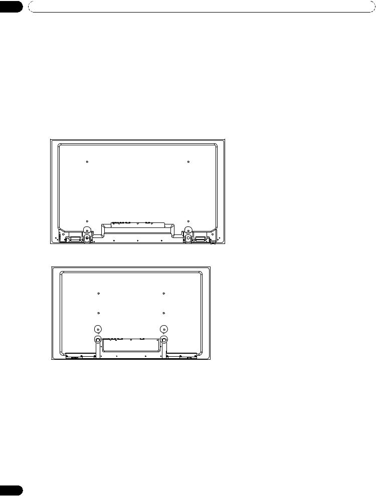
2.1Use the Optional Table Top Stand (Stand) or Equivalent Items
•Ask your dealer to perform the installation
•Use the supplied bolts
•For details, refer to the instruction manual that came with the optional stand (or equivalent items)
Rear view (PRO-141FD)
Rear view (PRO-101FD)
Use the supplied bolts when attaching the stand’s supports at the holes indicated by a circle.
12
En
Install Your Flat Panel Display |
02 |
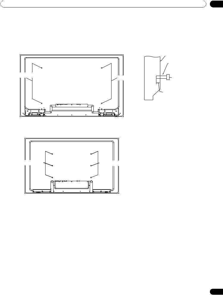
2.2Use the Optional Brackets or Equivalent Items
•Consult your dealer
•Use the following mounting holes for installation
Rear view (PRO-141FD) |
Side view |
|
Mounting surface |
||
|
||
|
Mounting |
|
|
bracket (or |
|
|
equivalent item) |
|
Mounting hole |
M8 screw |
|
Mounting hole |
||
|
12 mm to 18 mm |
|
|
(0.5 inches to |
|
|
0.7 inches) |
Rear view (PRO-101FD) |
|
Mounting hole |
Mounting hole |
Note: Some installation options require a different type of bolt. Check with your installer or dealer to purchase the appropriate bolt(s).
13
En
02 Install Your Flat Panel Display
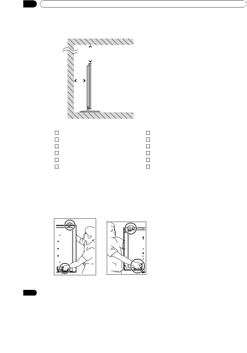
2.2.1Check the Location for Suitability
When choosing the location for your panel, there are several factors to keep in mind. The installation site should be out of direct sunlight and have sufficient ventilation around the flat panel display to allow cooling. The diagram below is an example of a stand-mounted panel with proper ventilation.
|
|
|
|
|
Over 50 cm |
|
|
|
|
|
|
|
|||
|
|
|
|
|
(19 11/16 inches) |
||
Over |
|
|
|
The distance behind and above the panel |
|||
|
|
|
|||||
10 cm |
|
|
|
|
|||
|
|
|
|
changes depending on your choice of mount. |
|||
(315/16 |
|
|
|
|
|
||
|
|
|
|
|
Consult with your dealer or professional |
||
inches) |
|
|
|
|
|||
|
|
|
|
installer for proper ventilation. |
|||
|
|
|
|
|
|
|
|
|
|
|
|
|
|
|
|
|
|
|
|
|
|
|
|
|
|
|
|
|
|
|
|
|
|
|
|
|
|
|
|
Use the checklist below to judge possible installation sites.
Sufficient ventilation |
No danger of power overloads |
Safe from excessive vibrations |
Separate from other IR equipment |
Away from air conditioners |
Protected from hits or shocks |
Free of moisture or dampness |
Distance from heat sources |
No danger of splashing water |
Out of direct sunlight |
Route cords and cables safely |
Away from strong lighting sources |
For specific cautions and safety information, refer to “8.2 Physical Location & Temperature Considerations” and “8.8 Safety Precautions.”
2.2.2Lift and/or Move Your Panel (the How To’s)
This flat panel display is built for endurance but because of the technology, the panel must be handled with care. Use the handles attached to the rear of the flat panel display to lift the unit. To avoid flexing or twisting the unit, you need at least two people to lift and move the panel. Do not move the flat panel display by holding only a single handle or by dragging the panel by its handles.
(PRO-141FD) (PRO-101FD)
Note: Do not use the handles to hang the flat panel display or as anchors to prevent the panel from slipping or
14 |
tipping after it is mounted. |
|
En
Install Your Flat Panel Display |
02 |
2.2.3Mount the Flat Panel Display
Because your flat panel display is slim but heavy, have at least two people mount and/or position the panel. The following sections provide instructions for the different mounting and anchoring options.
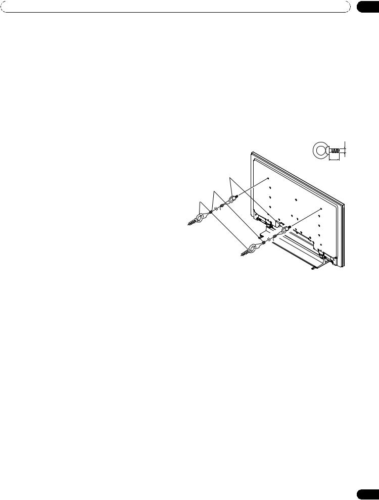
Anchor the Panel When Using a Stand
When using a stand, stabilize the panel to keep it from tipping over. Please use the metal fittings and screws supplied with the optional stand to anchor the panel to a wall or other solid support structure.
Another option is to purchase hooks, cords, and fittings through your installer or from your local hardware store. The hardware size and strength depends on the composition and thickness of the anchoring surface.
Recommended hook: Nominal diameter 8 mm (3/8 inch), length 12 mm to 18 mm (0.5 inches to 0.7 inches)
To anchor the panel when using the optional stand, follow the steps below.
1 ) Attach the hooks to the mounting holes on the |
M8 |
back of the panel. |
|
2 ) Sink the fittings into the wall or support structure. |
12 mm to 18 mm |
|
(0.5 inches to 0.7 inches) |
3 ) Run cords between the hooks and the fittings. |
1.Hook |
4 ) Tighten the cords until the panel is anchored but |
2.Cord |
not pulled off balance. |
Fitting |
(PRO-141FD)
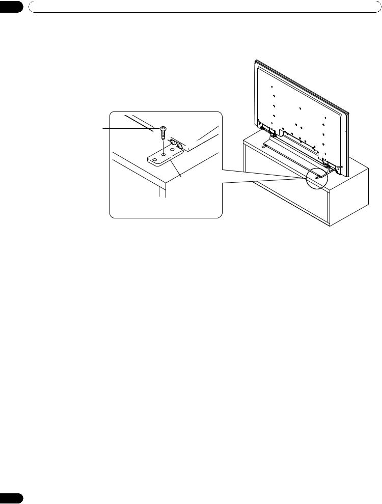
To stabilize the flat panel display on a table or platform, use the metal fittings and screws supplied with the optional stand as well as commercially available wood screws. The wood screws are to anchor the metal fittings when mounting on a wooden surface. These screws should have a nominal diameter of 4 mm (5/32 inch) and are at least 20 mm (13/16 inch) long.
Notes: Avoid moving the table after the panel is attached.
Do not use bare wires for the cord. If any part of the wire is introduced into the ventilation port on the back of the display panel, fire or electrical shock could result.
15
En
02 Install Your Flat Panel Display
Follow the steps below to secure your flat panel display.
1 ) Mark locations for metal fittings and screws on the back edge of the table using the panel stand to determine placement.
(PRO-141FD)
Wood screw (commercially available, 4 mm x 20 mm (5/32 inch x 13/16 inch) min.)
Falling prevention metal fitting (supplied with the optional stand)
2 ) Drill holes in the table or platform edge at the marked locations.
3 ) Lift panel into place with the assistance with at least one other person.
4 ) Use wood screws (not included) to secure the metal fittings to the table.
16
En
Install Your Flat Panel Display |
02 |
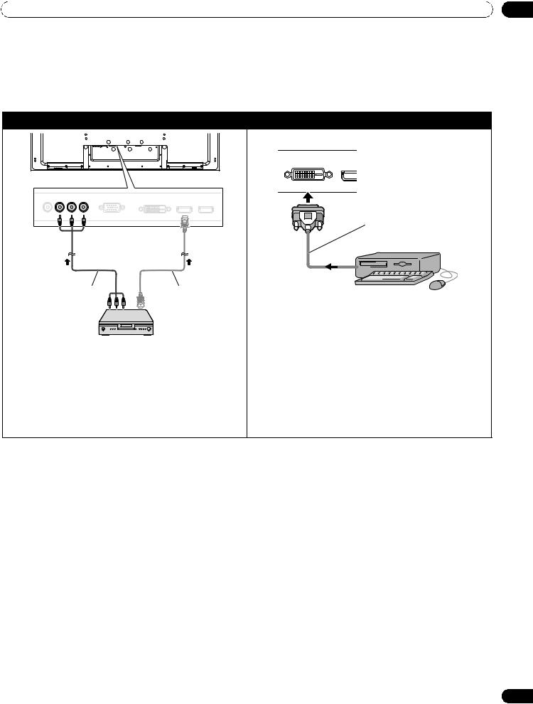
2.3Connect to Other Devices (DVR, Receiver, BDR, etc.)
The type of equipment attached to your flat panel display determines which panel ports are used. The following sections explain how to connect equipment such as a DVD player, video recorder, etc. to the panel. If your equipment is not listed, please refer to the operating instructions that came with the device(s) for connection assistance.
Connect a DVD player: |
Connect DVI equipment: |
Rear view
Rear view
DVI-D cable
(commercially available)
Component video cable |
HDMI compliant |
PC |
|
(commercially available) |
cable |
||
|
|||
|
(HDMI cable |
|
|
|
having the HDMI |
|
|
|
mark) |
|
|
|
DVD player |
Use a DVI-D 24-pin (digital only) cable to connect a PC |
|
|
|
equipped with a DVI output terminal (digital RGB |
|
|
|
signal). After completing connections, follow the on- |
|
Use INPUT 2 terminals when connecting a DVD player |
screen setup directions (page 52). INPUT 4 supports |
||
or other audio/visual equipment. If your DVD player has |
Microsoft “Plug & Play” (VESA DDC 2B) components. |
||
an HDMI terminal, use this connection instead of |
See “9.2 Video/PC Signals (HDMI/DVI/Component/min |
||
making video connections. For details, refer to the |
D-Sub/Composite)” for information about signals and |
||
operation manual that came with the DVD player. |
display formats supported by INPUT 4. |
||
17
En

02 Install Your Flat Panel Display
Connect a VCR: |
Connect HDMI equipment: |
Rear view |
Rear view |
|
Video cable |
HDMI compliant cable |
(commercially available) |
|
|
(HDMI cable having |
|
the HDMI mark) |
VCR |
|
|
Use INPUT 1 terminal when connecting a VCR or other |
HDMI equipment |
|
INPUT 5 through INPUT 8 are HDMI terminals. For |
||
recording equipment. For details, refer to the operation |
||
details, refer to “6.3 Use HDMI Inputs.” |
||
manual that came with the device. |
||
|
||
Connect a game console or camcorder: |
Connect a PC: |
|
|
|
|
|
|
|
|
|
|
|
|
|
|
|
|
|
|
|
|
|
|
|
|
|
|
|
|
|
|
|
|
|
|
|
|
|
|
|
|
|
|
|
|
|
|
|
|
|
|
|
|
|
|
|
|
|
|
|
|
|
|
|
|
|
|
|
|
|
|
|
|
|
|
|
|
|
|
|
|
|
|
|
|
|
|
|
|
|
|
|
|
|
|
|
|
|
|
|
|
|
|
|
|
|
|
|
|
|
|
|
|
|
|
|
|
|
|
|
|
|
|
|
|
|
|
|
|
|
|
|
|
|
|
|
|
|
|
|
|
|
|
|
|
|
|
|
|
|
|
|
|
|
|
|
|
|
|
|
|
|
|
|
|
|
|
|
|
|
|
|
|
|
|
|
|
|
|
|
|
|
|
|
|
|
|
|
|
|
|
|
|
|
|
|
|
|
|
|
|
|
|
|
|
|
|
|
|
|
|
|
|
Rear view |
|
|
|
Rear view |
||||||||||||||||||||||||||||||||||||||||||||||||
|
|
|
|
|
|
|
|
|
|
|
|
|
|
|
|
|
|
|
|
|
|
|
|
|
|
|
|
|
|
|
|
|
|
|
|
|
|
|
|
|
|
|
|
|
|
|
|
|
|
|
|
|
|
|
|
|
|
|
|
|
|
|
|
|
|
|
|
|
|
|
|
|
|
|
|
|
|
|
|
|
|
|
|
|
|
|
|
|
|
|
|
|
|
|
|
|
|
|
|
|
|
|
|
|
|
|
|
|
|
|
|
|
|
|
|
|
|
|
|
|
|
|
|
|
|
|
|
|
|
|
|
|
|
|
|
|
|
|
|
|
|
|
|
|
|
|
|
|
|
|
|
|
|
|
|
|
|
|
|
|
|
|
|
|
|
|
|
|
|
|
|
|
|
|
|
|
|
|
|
|
|
|
|
|
|
|
|
|
|
|
|
|
|
|
|
|
|
|
|
|
|
|
|
|
|
|
|
|
|
|
|
|
|
|
|
|
|
|
|
|
|
|
|
|
|
|
|
|
|
|
|
|
|
|
|
|
|
|
|
|
|
|
|
|
|
|
|
|
|
|
|
|
|
|
|
|
|
|
|
|
|
|
|
|
|
|
|
|
|
|
|
|
|
|
|
|
|
|
|
|
|
|
|
|
|
|
|
|
|
|
|
|
|
|
|
|
|
|
|
|
|
|
|
|
|
|
|
|
|
|
|
|
|
|
|
|
|
|
|
|
|
|
|
|
|
|
|
|
|
|
|
|
|
|
|
|
|
|
|
|
|
|
|
|
|
|
|
|
|
|
|
|
|
|
|
|
|
|
|
|
|
|
|
|
|
|
|
|
|
|
|
|
|
|
|
|
|
|
|
|
|
|
|
|
|
|
|
|
|
|
|
|
|
|
|
|
|
|
|
|
|
|
|
|
|
|
|
|
|
|
|
|
|
|
|
|
|
|
|
|
|
|
|
|
|
|
|
|
|
|
|
|
|
|
|
|
|
|
|
|
|
|
|
|
|
|
|
|
|
|
|
|
|
|
|
|
|
|
|
|
|
|
|
|
|
|
|
|
|
|
|
|
|
|
|
|
|
RGB cable |
Video cable |
(commercially available) |
(commercially available) |
|
|
Personal computer |
Camcorder/Game console |
|
Use INPUT 1 terminal when connecting a game |
|
console, camcorder, or other audio/visual |
Use INPUT 3 terminal (Analog RGB) when connecting |
equipment. For details, refer to the operation manual |
a computer (PC). For details, refer to the operation |
that came with the game console or camcorder. |
manual that came with the PC. |
18
En
Install Your Flat Panel Display |
02 |
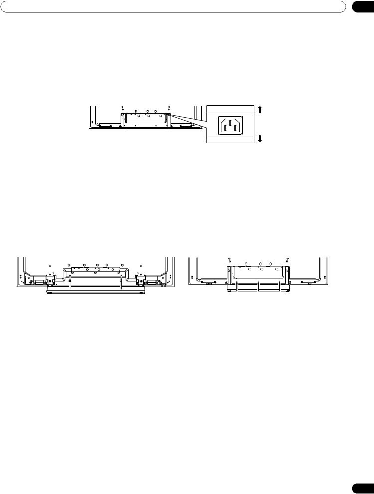
2.4Connect the Power Cord to the Panel
The final connection is the power cord. Always connect the panel’s power cord to a three-pronged outlet, verifying that the cord is properly grounded. The cord includes a noise filter. Using any other cord may fail to conform to mandatory FCC standards.
As long as the flat panel display is plugged in to an outlet, some power is drawn through the panel. When the flat panel display is not going to be used for a long period, unplug the panel from the power outlet. Unplugging the panel extends the life of the plasma as well as saves energy.
Plug the cord in to the panel but do NOT plug it in to a power outlet yet.
Rear
Front
2.5Route then Bundle the Power Cord and Cables
Once the flat panel display is mounted, place additional equipment in the final position(s). Lay out the power cord, panel cables, and any other device cables in a logical pattern that works for the location. Please consider the following points when routing cables:
•Access to a 3-prong (grounded) power outlet
•Space for the noise filter between the panel and outlet
•Placement of cables under carpets or across walking paths
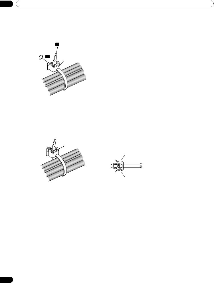
A reusable cable clamp is designed to lock the bundled cables in place. Your flat panel display has a total of three holes (60 inches: two holes) to attach cable clamps to the back of the panel. Use the cable clamps as necessary.
PRO-141FD |
PRO-101FD |
19
En
02 Install Your Flat Panel Display
Follow the steps below to attach a cable clamp.
1 ) Thread the clamp band through the holder and bundle the cable(s) in the cable clamp.
2 ) Push and hold the levers then insert the hook into an appropriate hole on the rear of the flat panel display.
3 ) Pull up the clamp band to lock.
1
2 |
Cable clamp |
|
4 ) Confirm that the cable clamp is seated firmly in the panel.
Note: Avoid pinching or creating pressure points when routing or bundling cables.
To remove the clamp band, pull and hold the latch to release.
To remove the cable clamp, push and hold the levers then pull it out from the hole.
Latch
Lever
Lever
Note: The longer a clamp is in place, the better chance of deterioration. An older clamp is more easily damaged while being removed and may not be reusable.
20
En
Basic Operations |
03 |
3 Basic Operations
This chapter explores day-to-day operations such as powering on your flat panel display, using the Home Menu, User Menu, and adjusting the display for the viewing area/room. The final section in this chapter provides hints and suggestions for those new to flat panel display features.
3.1Turn the Flat Panel Display ON / OFF
Your flat panel display has three activity levels: Power On, Standby, and Power Off. Standby saves energy but allows the remote control to turn on the panel. The following instructions use the remote control. To operate the flat panel display through the side panel buttons, refer to “1.2.1 Control Buttons and More on the Flat Panel Display” for button locations.
Turn ON the Flat Panel Display
To turn on the panel, follow the steps below.
1 ) Plug the flat panel display’s power cord in to a properly grounded outlet.
2 ) Press any of the following buttons to turn the flat panel display On.
•Power On button (a) on the panel’s back in lower-left section (see page 7)
•STANDBY/ON button on the side (PRO-141FD) or rear (PRO-101FD) of the panel (see page 7)
•Remote control’s MONITOR (a) button located in the upper left corner (see page 10)
Images appear on the panel screen.
3 ) Confirm that the Power On indicator lights blue.
(PRO-101FD)
Standby indicator Power On indicator
Note: While in Standby, pressing the remote control’s MONITOR ( a) button causes the flat panel display to turn On.
Turn OFF the Flat Panel Display
Turning off the flat panel display can mean entering Standby so features are still functional or it can mean cutting power to the panel. Unless the flat panel display is to sit idle for long periods, leave the panel in Standby.
Note: While in Standby or when powered off, the display continues to draw some power as long as the panel is plugged in to an outlet.
Follow the steps below to place the panel in Standby. 1 ) Press the remote control’s MONITOR ( a )
button.
2 ) Confirm that the Standby indicator lights red.
The table to the right provides samples of how the indicators light. Monitor the indicators on the front of the panel to check the power status.
Note: Select from Auto, High, Mid and Low. Selecting Auto toggles the brightness of the indicator between High, Mid and Low to match the brightness level of the viewing area. Refer to
“4.2.2 Adjust the Power Indicator Brightness.”
Power Standby
Flat Panel Display Status
Indicator Indicator
Panel’s power cord is disconnected or the power cord is connected but the flat panel display’s Power On button ( a ) is off
Power is on but waiting for activation
Panel is in Standby
21
En
03 Basic Operations
3.2Program Your Flat Panel Display
To take advantage of some built-in features, choose the input source, select a language and set the picture quality. The sections below include how to use the Home Menu and simplified User Menu for each programming option.
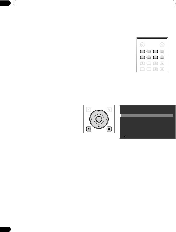
3.2.1Choose an Input Source
To choose an input source, note that the external equipment is properly |
|
|
|
|
|
connected to the input terminals on the back of the flat panel display. Follow |
MONITOR |
|
|
|
|
|
|
|
|
||
the directions below to choose an input source. |
|
INPUT |
|
||
Press INPUT (buttons 1 through 8) on the remote control. |
|
|
|||
1 |
2 |
3 |
4 |
||
|
|||||
The corresponding terminal/port number is selected as an input source. |
|
|
|
|
|
|
5 |
6 |
7 |
8 |
|
|
SPLIT |
SUB |
SWAP |
PIP |
|
|
INPUT |
SHIFT |
|||
|
AV |
AUTO |
FREEZE |
SCREEN |
|
|
SELECTION |
SETUP |
SIZE |
||
3.2.2Explore the Home Menu
The Home Menu is the main menu for the flat panel display. Most commands and settings are programmed through this menu. The following section describes a typical method for working with the panel’s menus. For actual procedures, see the appropriate page(s) that describe individual functions.
1) |
Press HOME MENU on the remote |
Remote control |
|
Home Menu screen |
|
to access the main menu. |
|
||
|
|
|
|
|
2) |
Use the Up/Down arrows (/) to |
EXIT |
USERMENU |
HOME MENU |
|
|
|||
|
|
FLAT PANEL DISPLAY |
||
|
highlight a menu item. |
TOPMENU |
TOOLS |
|
|
|
GUIDE |
|
Picture |
3) |
Use the Left/Right arrows (/) to |
|
|
|
ENTER |
|
Screen |
||
|
scroll through options for that menu |
|
|
Power Control |
|
HOME |
|
Option |
|
|
item. |
|
||
|
|
Input Setup |
||
|
MENU |
RETURN |
||
4) |
Highlight the selected menu option. |
|
|
Control Setup |
MENU |
|
|
||
5) |
Press ENTER to lock in the change. |
|
|
Exit |
|
|
|
6)Press RETURN to move back to a previous menu/submenu page when changing more than a single option.
7)Press HOME MENU again to exit the menu screen.
22
En

Basic Operations |
03 |
This chart provides a breakdown of the Home Menu.
Home Menu |
Pg |
Option |
|
Home Menu |
Pg |
Option |
Picture |
31 |
AV Selection |
|
Power Control |
29 |
Energy Save |
|
35 |
Contrast |
|
|
45 |
Power Management |
|
35 |
Brightness |
|
|
45 |
No Signal Off |
|
|
|
|
|
|
|
|
35 |
Color |
|
|
45 |
No Operation Off |
|
35 |
Tint |
|
Option |
24 |
Language |
|
35 |
Sharpness |
|
|
28 |
Input Priority |
|
|
|
|
|
|
|
|
37 |
Color Temp |
|
|
28 |
Blue LED Dimmer |
|
35 |
Red |
|
|
29 |
Orbiter |
|
35 |
Green |
|
|
29 |
Video Pattern |
|
|
|
|
|
|
|
|
35 |
Blue |
|
|
28 |
Long Life Settings |
|
38 |
Gamma |
|
|
25 |
Room Light Sensor |
|
38 |
Pro Adjust |
|
|
44 |
PIP Detect |
|
27 |
Reset |
|
Input Setup |
52 |
Input Setup 1/2 |
Screen |
53 |
Auto Setup |
|
|
52 |
Input Setup 2/2 |
|
26 |
H. Position |
|
Control Setup |
64 |
IP Control Setting |
|
26 |
V. Position |
|
|
58 |
KURO LINK Setting |
|
53 |
Clock |
|
|
69 |
Serial Setting |
|
53 |
Phase |
|
|
|
|
|
|
|
|
|
|
|
|
33 |
Auto Size |
|
|
|
|
|
36 |
Side Mask |
|
|
|
|
|
37 |
Reset |
|
|
|
|
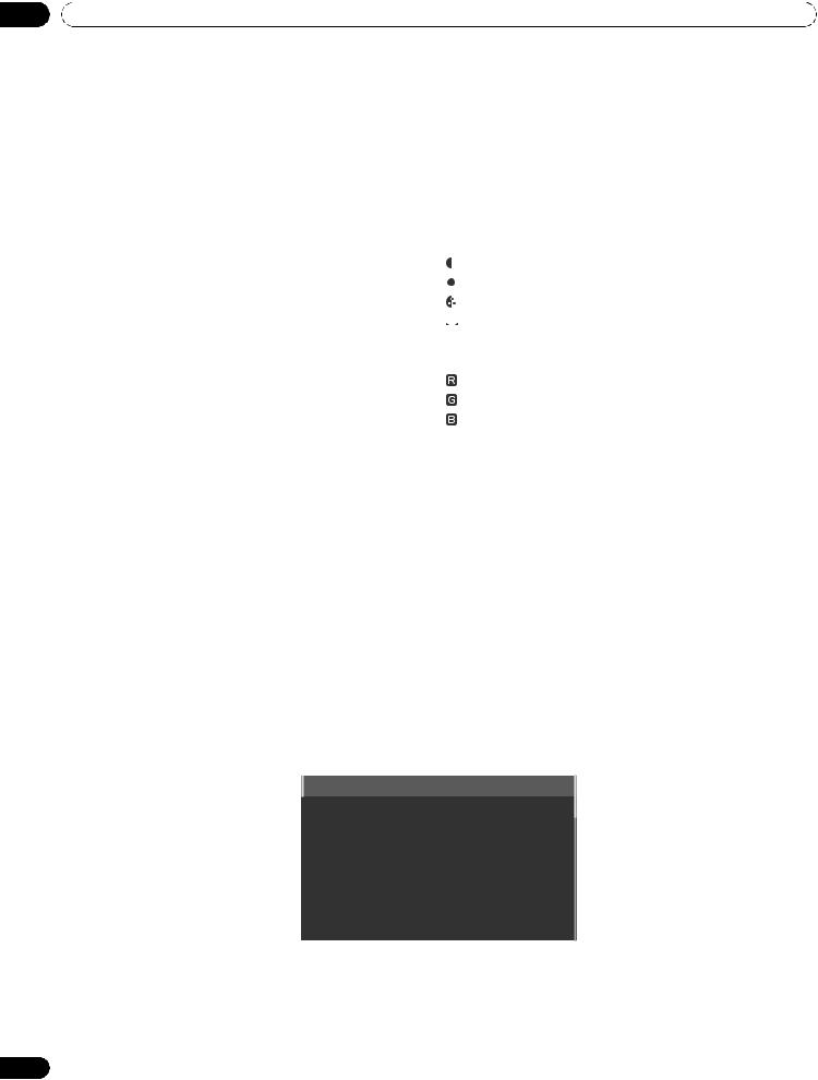
3.2.3Use the Simplified User Menu
For simplified menu selections, the User Menu provides quick access to frequently used menus/submenus. Press USER MENU on the remote control. For actual procedures, refer to “3.2.2 Explore the Home Menu”. The following table shows the available menus.
|
|
|
USER MENU |
|
|
User Menu screen |
|
|
|
|
|
|
|
|
|
|
FLAT PANEL DISPLAY |
|
|
|
|
|
|
|
|
|
|
|
Input Change |
|
|
|
|
|
|
AV Selection |
: |
Standard |
|
|
|
|
Film Mode |
: |
Off |
|
||
|
Sleep Timer |
|
|
|
|
|
|
KURO LINK |
|
|
|
|
|
|
Exit |
|
|
|
|
|
|
|
|
|
|
|
|
|
|
|
|
|
|
|
User Menu |
|
|
Function |
|||
|
|
|
|
|
||
Input Change |
|
switches external input sources |
||||
|
|
|
|
|
||
AV Selection |
|
selects from eight viewing modes depending on the |
||||
|
|
picture (see page 31) |
|
|
|
|
|
|
|
|
|
||
Film Mode |
|
reproduces theatre-quality images for film-based |
||||
|
|
sources (see page 38) |
|
|
|
|
|
|
|
|
|
||
Sleep Timer |
|
places the panel into Standby when the set time |
||||
|
|
elapses (see page 30) |
|
|
|
|
|
|
|
|
|
||
KURO LINK |
|
controls the connected equipment with the panel’s |
||||
|
|
remote through HDMI (see page 56) |
||||
|
|
|
|
|
|
|
23
En

03 Basic Operations
3.2.4Assign a Language
The default menu language is English. To assign a different language for menus and on-screen information, follow the steps below.
1 ) Access Language through the Option menu.
Language |
: |
English |
|
Input Priority |
: |
Off |
|
Blue LED Dimmer |
: |
Low |
|
Orbiter |
: |
Off |
|
Video Pattern |
: |
Off |
|
Long Life Settings |
: |
No |
|
Room Light Sensor |
: |
Off |
|
PIP Detect |
: |
Auto |
|
|
|
|
|
2 ) Select a language from the submenu.
3 ) Press HOME MENU to exit the menu.
24
En

Basic Picture Adjustment |
04 |
4 Basic Picture Adjustment
This chapter explores basic picture adjustment options for your flat panel display.
4.1Adjust the Picture Quality
Your flat panel display has many adjustment options for the picture to make it just right for you. This section provides basic adjustments but for detailed video modifications, refer to “5 Additional Picture Adjustment Options.”
4.1.1Adjust the Picture for Your Room Lighting
The flat panel display senses the amount of light in your room and automatically adjusts the screen brightness for the best picture. Bright rooms require stronger coloring so images appear crisp while dimly lit rooms allow the picture to use more subtle coloring.
The panel ships with the Room Light Sensor turned Off. The sections below provide directions to turn the room lighting sensor On/Off.
Room Lighting Sensor
To deactivate/reactivate the room lighting sensor, follow the steps below. 1 ) Access Room Light Sensor through the Option menu.
Language |
: |
English |
|
Input Priority |
: |
Off |
|
Blue LED Dimmer |
: |
Low |
|
Orbiter |
: |
Off |
|
Video Pattern |
: |
Off |
|
Long Life Settings |
: |
No |
|
Room Light Sensor |
: |
Off |
|
PIP Detect |
: |
Auto |
|
|
|
|
|
2 ) Select On (or Off ) from the submenu.
3 ) Press HOME MENU to exit the menu.
4.1.2General Picture (Video) Adjustment
The directions below apply to all AV Selection options except OPTIMUM and DYNAMIC. If the viewing option is OPTIMUM, your flat panel display automatically adjusts the picture to the best possible level. If the preferred viewing option is DYNAMIC, please refer to “5.1 Choose an AV Option (Video, Game, etc.).”
25
En
04 Basic Picture Adjustment
For standard picture adjustments, follow the steps below. 1 ) Press HOME MENU.
2 ) Select Picture from the main menu.
Use the arrow buttons to highlight an option then press ENTER.
3 ) Select an item to be adjusted.
Contrast is used in the example below.
|
Picture |
|
|
|
|
|
|
AV Selection |
: |
STANDARD |
|||||
Contrast |
: |
40 |
|
|
|
|
|
|
|
|
|
|
|||
Brightness |
: |
0 |
|
|
|
|
|
|
|
|
|
|
|||
Color |
: |
0 |
|
|
|
|
|
|
|
|
|
|
|||
Tint |
: |
0 |
|
|
|
|
|
|
|
|
|
|
|||
Sharpness |
: |
0 |
|
|
|
|
|
|
|
|
|
|
|||
Color Temp |
: |
Mid |
|||||
Red |
: |
0 |
|
|
|
|
|
|
|
|
|
|
|||
Green |
: |
0 |
|
|
|
|
|
|
|
|
|
|
|||
Blue |
: |
0 |
|
|
|
|
|
|
|
|
|
|
|||
Gamma |
: |
3 |
|
|
|
|
|
Pro Adjust |
|
|
|
|
|
|
|
Reset |
|
|
|
|
|
|
|
|
|
|
|
|
|
|
|
4 ) Use the arrow buttons (/) to adjust to the desired level.
|
Contrast |
32 |
|
|
|
|
|
|
|
|
|
5 ) Press HOME MENU again to exit the menu.
Picture Image Position
Each input source stores the picture adjustment settings for that view. Although repositioning is available in most screen views, when the screen is set to Dot by Dot, the Position menu is unavailable. Also, depending on the displayed video, the image position may not change after an adjustment.
To adjust the picture’s horizontal and vertical position, follow the steps below. 1 ) Access H.Position or V.Position through the Screen menu.
Auto Setup
H.Position
V.Position
Clock
Phase
Auto Size
Side Mask
Reset |
: |
No |
2 ) Adjust the vertical and/or horizontal positioning using the arrow buttons.
3 ) Press HOME MENU to exit the menu.
26
En

Basic Picture Adjustment |
04 |
Restore Default Picture
After making multiple adjustments, it may be difficult to reverse improper settings. To restore the factory default Picture settings, follow the directions below.
1 ) Access Reset from the Picture menu.
2 ) Press ENTER to continue with the picture reset.
3 ) Use the arrow buttons to highlight Yes.
4 ) Press ENTER.
All Picture settings return to the original default values.
4.1.3Compare Images When Adjusting the Picture
When adjusting the picture, look for an overall improvement by adjusting each parameter or option one at a time. Many small adjustments lead to the best picture for your viewing area. As each option changes, refer back to the previously set image for comparison. This section includes adjustment notes and steps to adjust the picture.
Each parameter/option must be adjusted separately. For example, if two options under AV Selection, STANDARD and MOVIE need adjustment, change/compare one option then save the preferred setting before moving on to the other option. Below are other guidelines for picture adjustment.
•Adjustments are available while on the After screen. Trying to make adjustments while on the Before causes a warning message to appear.
•Switch to another parameter/option only from the After screen. If viewing the Before screen when selecting another option, the Before data is lost.
•Exiting an option from the Before screen stores that previous entry in memory and deactivates the button.
•Exiting an option from the After screen stores the new entry in memory and deactivates the button.
•Moving/changing the AV Selection parameter/option stores the option setting in memory (the button continues to work).
Follow the steps below to adjust options for the preferred picture quality. 1 ) Press HOME MENU.
2 ) Select Picture from the main menu.
Use the arrow buttons to highlight an option then press ENTER.
3 ) Select an option.
4 ) Press USER MENU while the adjustment menu is on screen.
The word “Before” appears on screen with the unadjusted picture showing in Step 2.
5 ) Press USER MENU again.
The adjusted picture appears and the word “Before” disappears. Pressing USER MENU toggles the picture between Before and After.
6 ) Repeat Steps 3 through 5 to adjust other picture options.
7 ) Press HOME MENU again to exit the menu.
Notes: If no selections are made within 60 seconds, the menu closes automatically and the current settings are saved to memory.
“Before” is canceled if:
•The STANDBY/ON button, INPUT, SWAP or AV SELECTION is pressed
•input signal changes
To exit the menu without saving the changes, switch to the Before screen then press HOME MENU.
27
En

04 Basic Picture Adjustment
4.2Smart Starts for New Owners
Many of the flat panel display features make it easier to use but also environmentally friendlier. This section explains how to extend the life of your panel through being energy efficient. We suggest applying all of the following functions below for the simplest usage, best quality, and longest life span.
4.2.1Extend Your Panel Life
This function provides short-cuts to your panel’s longer service life. Your flat panel display includes a Long Life Settings option. Activating this option causes the panel to automatically select several different features that can prolong the life of your panel and help alleviate after-image ghosts or burn-in. To set this option, follow the steps below.
1 ) Access Long Life Settings through the Option menu.
A confirmation screen appears.
2 ) Select Yes from the submenu.
The following settings are automatically entered: •Auto Size: Wide Zoom
•Side Mask - Detection: Mode 1 •Orbiter (AV source): Mode 1 •Orbiter (PC source): Mode 1 •Energy Save: Save 1
•AV Selection: OPTIMUM (only when it was set to DYNAMIC previously)
3 ) Press HOME MENU to exit the menu.
4.2.2Adjust the Power Indicator Brightness
Adjust the brightness of the Power On indicator depending on the brightness level of the viewing area. Setting to Auto toggles the brightness of the indicator between High, Mid and Low to match the brightness level of the viewing area. To set the indicator, follow the directions below.
1 ) Access Blue LED Dimmer through the Option menu.
2 ) Select Auto, High, Mid or Low from the submenu.
3 ) Press HOME MENU to exit the menu.
4.2.3Set Input Priority
With a priority input assigned, the flat panel display automatically switches to that input when signals are present. To set the priority input, follow the directions below.
1 ) Access Input Priority through the Option menu.
2 ) Select Auto from the submenu.
3 ) Select the desired input.
Detecting another signal at a different input causes the selected input to automatically change to the new input.
After input changes, the previous input is not restored even when the signal disappears at the input.
4 ) Press HOME MENU to exit the menu.
28
En

Basic Picture Adjustment |
04 |
4.2.4Turn On the Image Orbiter
A built-in feature to protect against burn-in is the Orbiter function. Orbiter slightly changes the position of the picture while the image is on screen.
To activate Orbiter, follow the steps below.
1 ) Access Orbiter through the Option menu.
2 ) Select Mode 1, Mode 2 or Off.
•AV source Mode 1: for any screen mode except Dot by Dot
•AV source Mode 2: for all available screen modes
•PC source Mode 1: to enable Orbiter
•PC source Mode 2: to smooth the text/character appearance
3 ) Press HOME MENU to exit the menu.
Note: The farthest edges of an image may be hidden at times as the picture position shifts. Also, when the Orbiter function is set to Mode 1 or Mode 2, the image may appear to drop slightly on the screen.
4.2.5Trigger the Screen-Saving Video Pattern Periodically
The Video Pattern function causes the screen to appear white, which helps to alleviate after-image ghosts or burnin. While the Video Pattern screen is on, only the remote’s MONITOR (a) button and the panel’s STANDBY/ON button are available. The panel automatically switches to Standby one hour after running the Video Pattern screen. To cancel the Video Pattern screen, press the remote’s MONITOR (a) or press the panel’s STANDBY/ON button.
To activate the Video Pattern screen, follow the steps below. 1 ) Access Video Pattern through the Option menu.
A confirmation screen appears.
2 ) Select Start from the submenu.
The Video Pattern screen appears.
3 ) Leave the panel alone for a minimum of one hour.
Note: The Video Pattern timer has priority over Sleep Timer, No Signal Off, and No Operation Off (Power Management) settings.
4.2.6Activate Energy Save to Reduce Power Usage
The Energy Save option decreases picture brightness and lowers power consumption. The recommended setting, Save 1, extends the life of your panel while keeping power usage at a minimum.
Follow the steps below to activate an Energy Save option.
1 ) Access Energy Save through the Power Control menu.
2 ) Select an option from the Energy Save submenu.
Option |
Description |
|
|
Standard |
No effect |
|
|
Save 1 |
consumes less power than Standard |
|
|
Save 2 |
consumes less power than Save 1 |
|
|
Picture Off |
activates Picture Off when closing the Home Menu |
|
with this option selected |
|
|
3 ) Press HOME MENU to exit the menu.
Note: To deactivate the screen, select Picture Off.
29
En

04 Basic Picture Adjustment
4.2.7Turn On the Sleep Timer
To save energy and to maximize the life of your flat panel display, try using the Sleep Timer for occasions when the panel may be left on by accident. The Sleep Timer places the panel in Standby when the selected time elapses. The Sleep Timer provides time periods of 30, 60, 90, or 120 minutes. When the Timer is down to five minutes, a reminder appears on screen each minute until the time has elapsed.
To set the Sleep Timer, follow the steps below. 1 ) Press USER MENU.
2 ) Select Sleep Timer from the User Menu.
3 ) Select the desired time period.
Select between 30 minutes and two hours (120 minutes).
4 ) Press USER MENU again to exit the menu.
Note: When the sleep timer has been set, “Remain ---min” appears at the top of the menu.
The Video Pattern timer has priority over the sleep timer. When the Video Pattern timer is on, the sleep timer is deactivated. Video Pattern is explained in an earlier section in this manual.
30
En
 Loading...