


SX-SW570

HTS-570
SX-SW570
SSP-LX60D
Audio Multi-channel Receiver Subwoofer
Caisson de basse de rècepteur multi-voies audio
Speaker System
Enceintes acoustiques
Register Your Product at
http://www.pioneerelectronics.com (US)
http://www.pioneerelectronics.ca (Canada)
Operating Instructions
Mode d’emploi
The lightning flash with arrowhead, within
an equilateral triangle, is intended to alert
the user to the presence of uninsulated
"dangerous voltage" within the product's
enclosure that may be of sufficient
magnitude to constitute a risk of electric
shock to persons.
Ce symbole de l’éclair, placé dans un
triangle équilatéral, a pour but d’attirer
l’attention de l’utilisateur sur la présence, à
l’intérieur du coffret de l’appareil, de
“tensions dangereuses” non isolées d’une
grandeur suffisante pour représenter un
risque d’électrocution pour les êtres
humains.
CAUTION
RISK OF ELECTRIC SHOCK
DO NOT OPEN
CAUTION:
TO PREVENT THE RISK OF ELECTRIC
SHOCK, DO NOT REMOVE COVER (OR
BACK). NO USER-SERVICEABLE PARTS
INSIDE. REFER SERVICING TO QUALIFIED
SERVICE PERSONNEL.
ATTENTION
DANGER D´ELECTROCUTION
NE PAS OUVRIR
ATTENTION:
POUR ÉVITER TOUT RISQUE
D’ÉLECTROCUTION, NE PAS ENLEVER LE
COUVERCLE (NI LE PANNEAU ARRIÈRE).
AUCUNE PIÈCE RÉPARABLE PAR
L’ UTILISATEUR NE SE TROUVE À
L’ INTÉRIEUR. CONFIER TOUT ENTRETIEN À
UN PERSONNEL QUALIFIÉ UNIQUEMENT.
The exclamation point within an equilateral
triangle is intended to alert the user to the
presence of important operating and
maintenance (servicing) instructions in the
literature accompanying the appliance.
D1-4-2-3_En
Ce point d’exclamation, placé dans un
triangle équilatéral, a pour but d’attirer
l’attention de l’utilisateur sur la présence,
dans les documents qui accompagnent
l’appareil, d’explications importantes du
point de vue de l’exploitation ou de
l’entretien.
D1-4-2-3_Fr
WARNING – TO PREVENT FIRE OR SHOCK
HAZARD, DO NOT EXPOSE THIS
APPLIANCE TO RAIN OR MOISTURE.
D1-4-2-1_En
AVERTISSEMENT
Cet appareil n’est pas étanche. Pour éviter les
risques d’incendie et de décharge électrique, ne
placez près de lui un récipient rempli d’eau, tel
qu’un vase ou un pot de fleurs, et ne l’exposez pas
à des gouttes d’eau, des éclaboussures, de la pluie
ou de l’humidité.
D3-4-2-1-3_A_Fr
CAUTION: This product satisfies FCC regulations when shielded cables and connectors are used to connect the
unit to other equipment. To prevent electromagnetic interference with electric appliances such as radios and
televisions, use shielded cables and connectors for connections.
D8-10-3a_En
NOTE: This equipment has been tested and found to comply with the limits for a Class B digital device, pursuant to
Part 15 of the FCC Rules. These limits are designed to provide reasonable protection against harmful interference in
a residential installation. This equipment generates, uses, and can radiate radio frequency energy and, if not
installed and used in accordance with the instructions, may cause harmful interference to radio communications.
However, there is no guarantee that interference will not occur in a particular installation. If this equipment does
cause harmful interference to radio or television reception, which can be determined by turning the equipment off
and on, the user is encouraged to try to correct the interference by one or more of the following measures:
– Reorient or relocate the receiving antenna.
– Increase the separation between the equipment and receiver.
– Connect the equipment into an outlet on a circuit different from that to which the receiver is connected.
– Consult the dealer or an experienced radio/TV technician for help.
D8-10-1-2_En
Information to User
Alteration or modifications carried out without appropriate authorization may invalidate the user’s right to operate
the equipment.
D8-10-2_En
IMPORTANT NOTICE – THE SERIAL NUMBER FOR THIS EQUIPMENT IS LOCATED IN THE REAR.
PLEASE WRITE THIS SERIAL NUMBER ON YOUR ENCLOSED WARRANTY CARD AND
KEEP IN A SECURE AREA. THIS IS FOR YOUR SECURITY.
D1-4-2-6-1_En
READ INSTRUCTIONS — All the safety and
T
operating instructions should be read before the
product is operated.
RETAIN INSTRUCTIONS — The safety and
operating instructions should be retained for
future reference.
HEED WARNINGS — All warnings on the product
and in the operating instructions should be
adhered to.
FOLLOW INSTRUCTIONS — All operating and use
instructions should be followed.
CLEANING — The product should be cleaned only
with a polishing cloth or a soft dry cloth. Never
clean with furniture wax, benzine, insecticides
or other volatile liquids since they may corrode
the cabinet.
ATTACHMENTS — Do not use attachments not
recommended by the product manufacturer as
they may cause hazards.
WATER AND MOISTURE — Do not use this
product near water — for example, near a
bathtub, wash bowl, kitchen sink, or laundry
tub; in a wet basement; or near a swimming
pool; and the like.
ACCESSORIES — Do not place this product on an
unstable cart, stand, tripod, bracket, or table.
The product may fall, causing serious injury to a
child or adult, and serious damage to the
product. Use only with a cart, stand, tripod,
bracket, or table recommended by the
manufacturer, or sold with the product. Any
mounting of the product should follow the
manufacturer’s instructions, and should use a
mounting accessory recommended by the
manufacturer.
CART — A product and cart combination should be
moved with care. Quick stops, excessive force,
and uneven surfaces may cause the product
and cart combination to overturn.
VENTILATION — Slots and openings in the cabinet
are provided for ventilation and to ensure
reliable operation of the product and to protect
it from overheating, and these openings must
not be blocked or covered. The openings should
never be blocked by placing the product on a
bed, sofa, rug, or other similar surface. This
product should not be placed in a built-in
installation such as a bookcase or rack unless
proper ventilation is provided or the
manufacturer’s instructions have been adhered
to.
POWER SOURCES — This product should be
operated only from the type of power source
indicated on the marking label. If you are not
sure of the type of power supply to your home,
consult your product dealer or local power
company.
LOCATION – The appliance should be installed in a
stable location.
NONUSE PERIODS – The power cord of the
appliance should be unplugged from the outlet
when left un-used for a long period of time.
GROUNDING OR POLARIZATION
• If this product is equipped with a polarized
alternating current line plug (a plug having one
blade wider than the other), it will fit into the
outlet only one way. This is a safety feature. If
you are unable to insert the plug fully into the
outlet, try reversing the plug. If the plug should
still fail to fit, contact your electrician to replace
your obsolete outlet. Do not defeat the safety
purpose of the polarized plug.
• If this product is equipped with a three-wire
grounding type plug, a plug having a third
(grounding) pin, it will only fit into a grounding
type power outlet. This is a safety feature. If you
are unable to insert the plug into the outlet,
contact your electrician to replace your obsolete
outlet. Do not defeat the safety purpose of the
grounding type plug.
POWER-CORD PROTECTION — Power-supply
cords should be routed so that they are not likely
to be walked on or pinched by items placed
upon or against them, paying particular
attention to cords at plugs, convenience
receptacles, and the point where they exit from
the product.
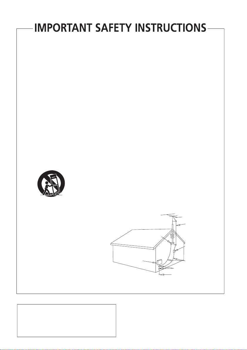
OUTDOOR ANTENNA GROUNDING — If an
outside antenna or cable system is connected to
the product, be sure the antenna or cable
system is grounded so as to provide some
protection against voltage surges and built-up
static charges. Article 810 of the National
Electrical Code, ANSI/NFPA 70, provides
information with regard to proper grounding of
the mast and supporting structure, grounding of
the lead-in wire to an antenna discharge unit,
size of grounding conductors, location of
antenna-discharge unit, connection to
grounding electrodes, and requirements for the
grounding electrode. See Figure A.
LIGHTNING — For added protection for this
product during a lightning storm, or when it is
left unattended and unused for long periods of
time, unplug it from the wall outlet and
disconnect the antenna or cable system. This
will prevent damage to the product due to
lightning and power-line surges.
POWER LINES — An outside antenna system
should not be located in the vicinity of overhead
power lines or other electric light or power
circuits, or where it can fall into such power
lines or circuits. When installing an outside
antenna system, extreme care should be taken
to keep from touching such power lines or
circuits as contact with them might be fatal.
OVERLOADING — Do not overload wall outlets,
extension cords, or integral convenience
receptacles as this can result in a risk of fire or
electric shock.
ELECTRIC
SERVICE
EQUIPMENT
Fig. A
OBJECT AND LIQUID ENTRY — Never push
objects of any kind into this product through
openings as they may touch dangerous voltage
points or short-out parts that could result in a
fire or electric shock. Never spill liquid of any
kind on the product.
SERVICING — Do not attempt to service this
product yourself as opening or removing covers
may expose you to dangerous voltage or other
hazards. Refer all servicing to qualified service
personnel.
DAMAGE REQUIRING SERVICE — Unplug this
product from the wall outlet and refer servicing
to qualified service personnel under the
following conditions:
• When the power-supply cord or plug is
damaged.
• If liquid has been spilled, or objects have fallen
into the product.
• If the product has been exposed to rain or water.
• If the product does not operate normally by
following the operating instructions. Adjust only
those controls that are covered by the operating
instructions as an improper adjustment of other
controls may result in damage and will often
require extensive work by a qualified technician
to restore the product to its normal operation.
• If the product has been dropped or damaged in
any way.
• When the product exhibits a distinct change in
performance — this indicates a need for service.
REPLACEMENT PARTS — When replacement parts
are required, be sure the service technician has
used replacement parts specified by the
manufacturer or have the same characteristics
as the original part. Unauthorized substitutions
may result in fire, electric shock, or other
hazards.
SAFETY CHECK — Upon completion of any service
or repairs to this product, ask the service
technician to perform safety checks to
determine that the product is in proper
operating condition.
WALL OR CEILING MOUNTING — The product
should not be mounted to a wall or ceiling.
HEAT — The product should be situated away from
heat sources such as radiators, heat registers,
stoves, or other products (including amplifiers)
that produce heat.
ANTENNA
LEAD IN
GROUND
CLAMP
WIRE
ANTENNA
DISCHARGE UNIT
(NEC SECTION 810-20)
GROUNDING CONDUCTORS
(NEC SECTION 810-21)
GROUND CLAMPS
POWER SERVICE GROUNDING
ELECTRODE SYSTEM
(NEC ART 250, PART H)
NEC — NATIONAL ELECTRICAL CODE
D1-4-2-2_En
This product is for general household purposes. Any
failure due to use for other than household purposes
(such as long-term use for business purposes in a
restaurant or use in a car or ship) and which
requires repair will be charged for even during the
warranty period.
K041_En
his product contains mercury. Disposal of this
material may be regulated due to environmental
considerations. For disposal or recycling information,
please contact your local authorities or the Electronics
Industries Alliance : www.eiae.org.
K057_En
POWER-CORD CAUTION
T
Handle the power cord by the plug. Do not pull out the
plug by tugging the cord and never touch the power
cord when your hands are wet as this could cause a
short circuit or electric shock. Do not place the unit, a
piece of furniture, etc., on the power cord, or pinch the
cord. Never make a knot in the cord or tie it with other
cords. The power cords should be routed such that they
are not likely to be stepped on. A damaged power cord
can cause a fire or give you an electrical shock. Check
the power cord once in a while. When you find it
damaged, ask your nearest PIONEER authorized
service center or your dealer for a replacement.
S002_En
NOTE IMPORTANTE SUR LE CABLE
D’ALIMENTATION
enir le câble d’alimentation par la fiche. Ne pas
débrancher la prise en tirant sur le câble et ne pas
toucher le câble avec les mains mouillées. Cela risque
de provoquer un court-circuit ou un choc électrique. Ne
pas poser l’appareil ou un meuble sur le câble. Ne pas
pincer le câble. Ne pas faire de noeud avec le câble ou
l’attacher à d’autres câbles. Les câbles d’alimentation
doivent être posés de façon à ne pas être écrasés. Un
câble abîmé peut provoquer un risque d’incendie ou un
choc électrique. Vérifier le câble d’alimentation de
temps en temps. Contacter le service après-vente
PIONEER le plus proche ou le revendeur pour un
remplacement.
S002_Fr
For U.S. and Australia Model
C67-7-3_En
Ce produit est destiné à une utilisation domestique
générale. Toute panne due à une utilisation autre
qu'à des fins privées (comme une utilisation à des
fins commerciales dans un restaurant, dans un
autocar ou sur un bateau) et qui nécessite une
réparation sera aux frais du client, même pendant la
période de garantie.
K041_Fr
WARNING: Handling the cord on this product or
cords associated with accessories sold with the
product will expose you to chemicals listed on
proposition 65 known to the State of California and
other governmental entities to cause cancer and
birth defect or other reproductive harm.
Wash hands after handling
D36-P4_A_En
This Class B digital apparatus complies with Canadian ICES-003.
Cet appareil numérique de la Classe B est conforme à la norme NMB-003 du Canada.
D8-20-1_EF

Selecting fine audio equipment such as the unit
you’ve just purchased is only the start of your
musical enjoyment. Now it’s time to consider how
you can maximize the fun and excitement your
equipment offers. This manufacturer and the
Electronic Industries Association’s Consumer
Electronics Group want you to get the most out of
your equipment by playing it at a safe level. One that
lets the sound come through loud and clear without
annoying blaring or distortion-and, most importantly,
without affecting your sensitive hearing.
Sound can be deceiving. Over time your hearing
“comfort level” adapts to higher volumes of sound.
So what sounds “normal” can actually be loud and
harmful to your hearing. Guard against this by
setting your equipment at a safe level BEFORE your
hearing adapts.
To establish a safe level:
• Start your volume control at a low setting.
• Slowly increase the sound until you can hear it
comfortably and clearly, and without distortion.
Once you have established a comfortable sound
level:
• Set the dial and leave it there.
Taking a minute to do this now will help to prevent
hearing damage or loss in the future. After all, we
want you listening for a lifetime.
We Want You Listening For A Lifetime
Used wisely, your new sound equipment will
provide a lifetime of fun and enjoyment. Since
hearing damage from loud noise is often
undetectable until it is too late, this manufacturer
and the Electronic Industries Association’s
Consumer Electronics Group recommend you avoid
prolonged exposure to excessive noise. This list of
sound levels is included for your protection.
Decibel
Level Example
30 Quiet library, soft whispers
40
Living room, refrigerator, bedroom away from traffic
50 Light traffic, normal conversation, quiet office
60 Air conditioner at 20 feet, sewing machine
70 Vacuum cleaner, hair dryer, noisy restaurant
Average city traffic, garbage disposals, alarm clock
80
at two feet.
THE FOLLOWING NOISES CAN BE DANGEROUS
UNDER CONSTANT EXPOSURE
90
Subway, motorcycle, truck traffic, lawn mower
100 Garbage truck, chain saw, pneumatic drill
120 Rock band concert in front of speakers,
thunderclap
140 Gunshot blast, jet plane
180 Rocket launching pad
Information courtesy of the Deafness Research Foundation.
S001_En
English
What’s in the box
Please confirm that the following items are all supplied.
Receiver subwoofer (SX-SW570) box:
• Remote control (page 16)
• AA/R6 dry cell batteries (to confirm operation) x2
(page 17)
• Display unit (page 15)
• Power cord (page 14)
• AM loop antenna (page 12)
• FM wire antenna (page 12)
• Display cable (page 11)
• Coaxial cable (page 27)
• Microphone (for Auto MCACC setup) (page 18)
• Non-skid pads (large) x4 (page 8, 9)
• Spacers x2 (page 11)
• This operating instructions
• Warranty card
Speakers (SSP–LX60D) box:
• Speakers (front x2, surround x2, center x2) (page 13)
• Speaker cables x5 (page 12)
• Non-skid pads (small) x24 (page 8, 9)
• Brackets x2 (page 8, 9)
• Spiral wrap x2 (page 13)
• Screws x8 (page 8)
5
En

Contents
Thank you for buying this Pioneer product.
Please read through these operating instructions so that you will know how to operate your model properly. After you
have finished reading the instructions, put them in a safe place for future reference
.
Contents
What’s in the box
01 Speaker Setup Guide...............................
Safety precautions when setting up
Home theater sound setup
Front surround setup (recommended)
Standard surround setup
Wall mounting the speakers
Before mounting
Additional notes on speaker placement
02 Connecting up .......................................
Basic connections
Wall mounting the display unit
Using this system for TV audio
. . . . . . . . . . . . . . . . . . . . . . . . . . . . .5
. . . . . . . . . . . . . . .7
. . . . . . . . . . . . . . . . . . . . . .7
. . . . . . . . . . . .7
. . . . . . . . . . . . . . . . . . . . . .9
. . . . . . . . . . . . . . . . . . . .10
. . . . . . . . . . . . . . . . . . . . . . . . . . .10
. . . . . . . . . . .10
11
. . . . . . . . . . . . . . . . . . . . . . . . . . .11
. . . . . . . . . . . . . . . . .14
. . . . . . . . . . . . . . . . . .14
06 Listening to the radio ...........................
Listening to the radio
Improving poor FM reception
7
Improving poor AM sound
Memorizing stations
Listening to station presets
Changing the frequency step
. . . . . . . . . . . . . . . . . . . . . . . . .23
. . . . . . . . . . . . . . . . . .23
. . . . . . . . . . . . . . . . . . . .23
. . . . . . . . . . . . . . . . . . . . . . . . .23
. . . . . . . . . . . . . . . . . . .23
. . . . . . . . . . . . . . . . . .24
07 Surround sound settings ......................
Using the Setup menu
Channel level setting
Speaker distance setting
Dynamic Range Control
Dual mono setting
Adjusting the channel levels using the test tone
. . . . . . . . . . . . . . . . . . . . . . . .25
. . . . . . . . . . . . . . . . . . . . . . . .25
. . . . . . . . . . . . . . . . . . . . .25
. . . . . . . . . . . . . . . . . . . . . .25
. . . . . . . . . . . . . . . . . . . . . . . . . .26
23
25
. . . . .26
03 Controls and displays ...........................
Display unit
Display
Remote control
Using the remote control
Putting the batteries in the remote control
. . . . . . . . . . . . . . . . . . . . . . . . . . . . . . . .15
. . . . . . . . . . . . . . . . . . . . . . . . . . . . . . . . . . .15
. . . . . . . . . . . . . . . . . . . . . . . . . . . . . .16
. . . . . . . . . . . . . . . . . . . . . .17
04 Getting started......................................
System demo setting
Using the Auto MCACC setup for optimal surround
. . . . . . . . . . . . . . . . . . . . . . . . . . . . . . . . . . . . .18
sound
. . . . . . . . . . . . . . . . . . . . . . . . .18
05 Listening to your system......................
Auto listening mode
Listening in surround sound
Dolby Pro Logic II Music settings
Using Front Stage Surround Advance
Using Advanced Surround
Listening in stereo
Using the Sound Retriever
Listening with Acoustic Calibration EQ
Enhancing dialogue
Using Quiet and Midnight listening modes
Adjusting the bass and treble
Boosting the bass level
6
En
. . . . . . . . . . . . . . . . . . . . . . . . . .20
. . . . . . . . . . . . . . . . . . . .20
. . . . . . . . . . . . . . . . . . . . .21
. . . . . . . . . . . . . . . . . . . . . . . . . . .21
. . . . . . . . . . . . . . . . . . . . .21
. . . . . . . . . . . . . . . . . . . . . . . . . .22
. . . . . . . . . . . . . . . . . . .22
. . . . . . . . . . . . . . . . . . . . . . . .22
15
. . . . . . . . .17
18
20
. . . . . . . . . . . . . . .20
. . . . . . . . . . . .21
. . . . . . . . . . . .22
. . . . . . . .22
08 Other connections .................................
Connecting auxiliary components
Connecting an analog audio component
Listening to an external audio source
Connecting external antennas
Using this unit with a Pioneer plasma display
SR+ Setup for Pioneer plasma displays
Using the SR+ mode
with a Pioneer plasma display
About control out connections
. . . . . . . . . . . . . . .27
. . . . . . . . .27
. . . . . . . . . . . . .27
. . . . . . . . . . . . . . . . . .27
. . . . . . . . . .28
. . . . . . . . . . . . . . . . .29
. . . . . . . . . . . . . . . . . .29
09 Additional information.........................
Setting the sleep timer
Dimming the display
DTS CD setting
Resetting the system
Installation and maintenance
Hints on installation
Setting up the remote to control your TV
Using the TV remote control buttons
Preset code list
Troubleshooting
General
. . . . . . . . . . . . . . . . . . . . . . . . . . . . . . . . . .33
Tuner
. . . . . . . . . . . . . . . . . . . . . . . . . . . . . . . . . . . .34
Error Messages . . . . . . . . . . . . . . . . . . . . . . . . . . . .34
Glossary . . . . . . . . . . . . . . . . . . . . . . . . . . . . . . . . . . .34
Specifications. . . . . . . . . . . . . . . . . . . . . . . . . . . . . . .35
. . . . . . . . . . . . . . . . . . . . . . . .30
. . . . . . . . . . . . . . . . . . . . . . . . .30
. . . . . . . . . . . . . . . . . . . . . . . . . . . . . .30
. . . . . . . . . . . . . . . . . . . . . . . . .30
. . . . . . . . . . . . . . . . . . .31
. . . . . . . . . . . . . . . . . . . . . . . . .31
. . . . . . . . . . .31
. . . . . . . . . . . .31
. . . . . . . . . . . . . . . . . . . . . . . . . . . .32
. . . . . . . . . . . . . . . . . . . . . . . . . . . . .33
27
. . . . . .28
30
Speaker Setup Guide
Center
Front left
Front right
Surround left
Surround right
Bass
Center
Front left
Front right
Surround left
Surround right
Bass
Listening position
01
Chapter 1
Speaker Setup Guide
Safety precautions when setting up
When assembling the speakers, lay them down flat on
their side to avoid accidents or injury. Make sure to use a
stable surface when assembling, setting up, and placing
the speakers.
If the speakers are to be used in a stacked configuration,
always use the provided brackets to secure them
together (page 8, 9).
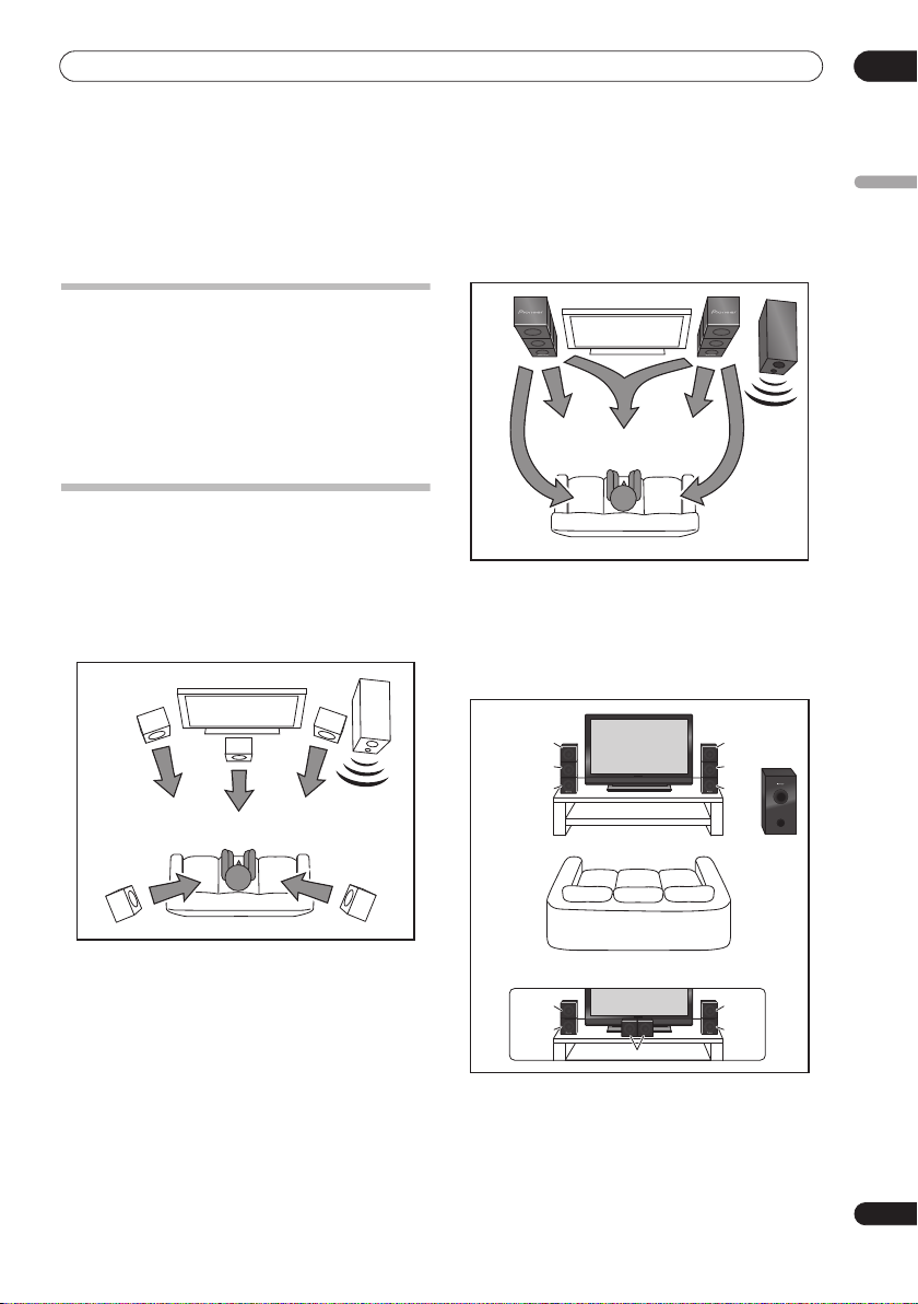
Home theater sound setup
Most 5.1 channel home theater systems are designed so
that speakers are placed to surround the listener’s
position as shown in the illustration. Such designs,
however, produce the undesirable effect of forcing the
center speaker to be mounted above or below the
television monitor, and require room for the surround
speakers.
Bass
Surround right
Surround left
Front left
Center
Front right
Surround left
Front surround setup (recommended)
This recommended method places the surround
speakers in front, to simplify the issue of speaker
placement in the room. The center speakers can be
placed in independently in the center if desired.
Surround
Center
Front
Front left
left
left
Center
Listening position
Front right
Surround right
Surround
right
Center
Front
right
Bass
Receiver
subwoofer
English
The present system, however, features Pioneer’s
proprietary New Front Surround technology and Dual
Center Speakers, using only two speaker positions (to
right and left of television as shown in the illustration) in
order to provide full home theater sound while greatly
simplifying the issue of speaker placement.
*When center speakers are placed in the center.
Surround
left
Front
left
Center
Surround
right
Front
right
7
En
01
Speaker Setup Guide
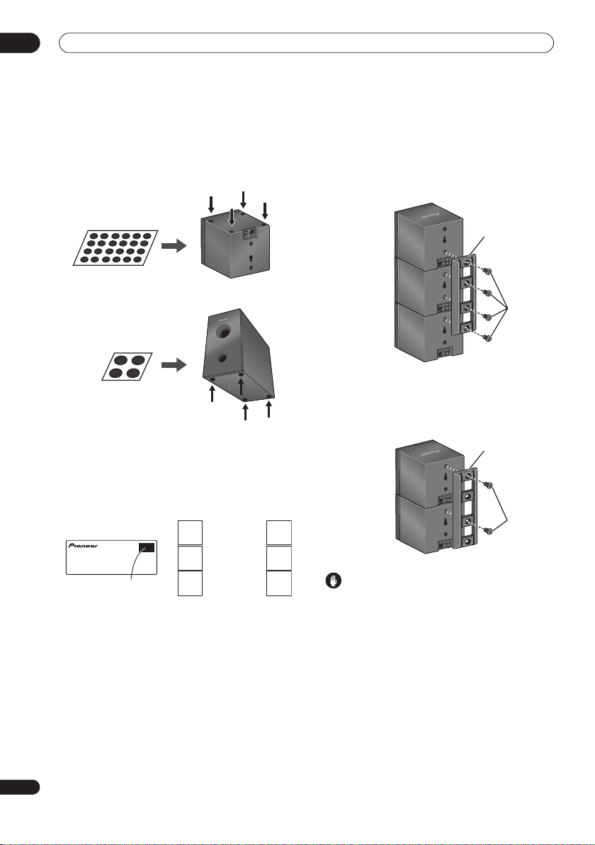
1 Attach the smaller non-skid pads to the base of
each of the front, center and surround speakers. The
four large non-skid pads are for the receiver
subwoofer (as shown).
Use the adhesive side of the pads to attach them to the
base (flat surface) of each speaker.
Non-skid pads
(small) x 24
Non-skid pads
(large) x 4
Front, Center and Surround speakers
Receiver subwoofer
2 Stack the speakers and fix with the brackets.
Each speaker is provided with a color-coded indicator on
the model label on the rear side to assist identification.
Refer to the color indicators and install the speakers
correctly.
Model label
Left
Blue
Green
Surround speaker
Center speaker
Right
Gray
Green
As shown in the illustration, stack the speakers from the
bottom up in the order front speaker, center speaker,
surround speaker. Align the bracket with the respective
upper screw hole on the back of the front speaker, the
two screw holes on the center speaker, and the bottom
screw hole on the surround speaker, and fasten the
screws securely.
Surround speaker
Center speaker
Front speaker
Bracket
Screw
When placing the center speakers independently, stack
the front speaker on the bottom and the surround
speaker on top, then align the 1st and 3rd screw holes
from the top of the bracket with the upper screw holes on
the back of the speakers, and fasten the two securely.
Bracket
Surround speaker
Front speaker
Screw
Color indicator
White
Front speaker
Red
Caution
• Do not attempt to carry the speakers when they are
connected with the bracket. Doing so may cause
damage to the bracket or worsen damage to the
bracket and speakers in the event they are dropped.
3 Connect the speaker system.
Refer to
Connecting up
to connect the speakers properly.
After connecting everything, place the speakers as
shown in the diagram above for optimal surround sound.
After placing the speakers, run the Auto MCACC setup
(page 18) to complete your surround sound setup.
8
En
Speaker Setup Guide
Listening position
01
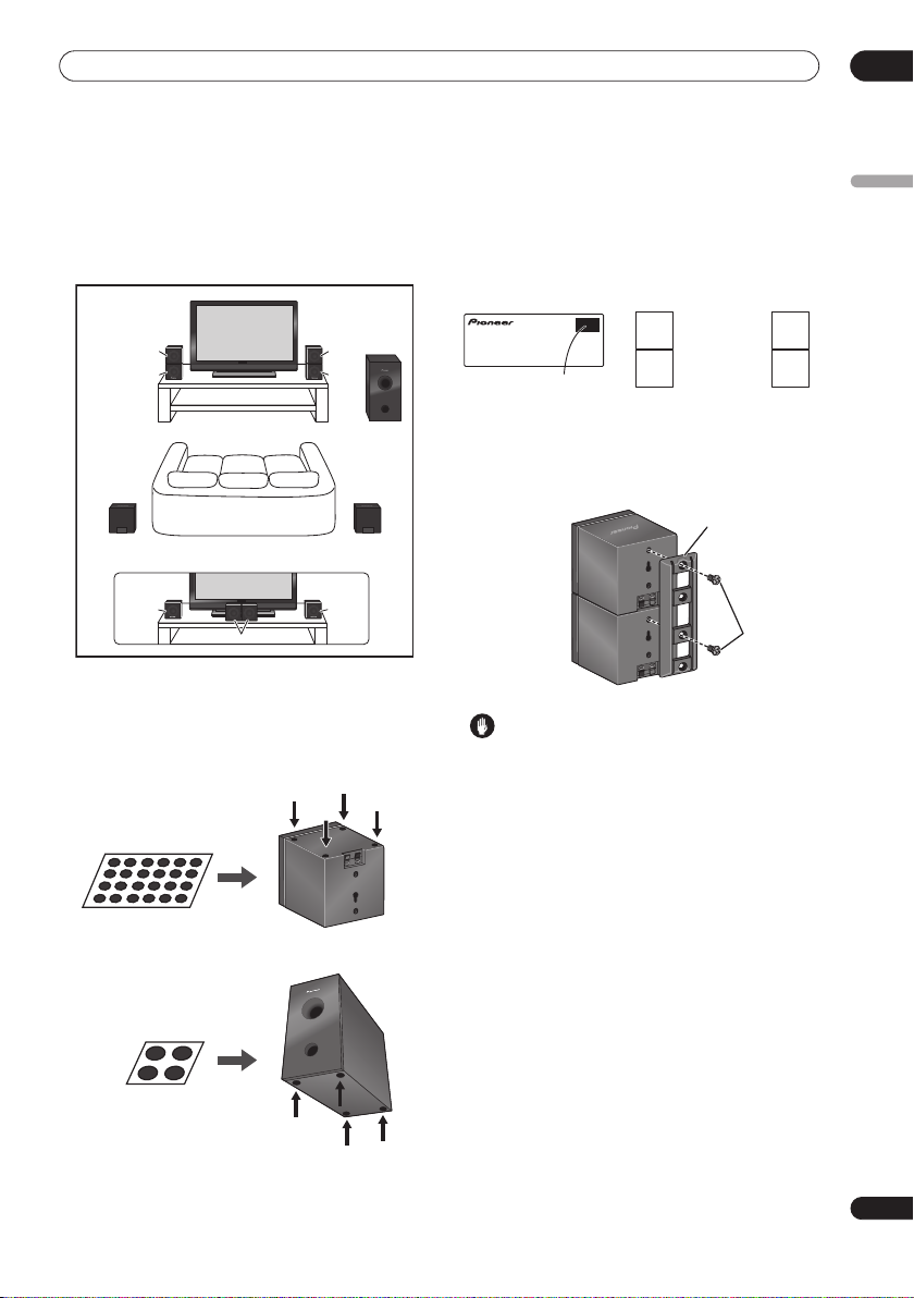
Standard surround setup
This is a standard multichannel surround sound speaker
setup for optimal 5.1 channel home theater sound.
The center speakers can be installed independently in
the center if desired.
Front
left
Listening position
Surround left
*When center speakers are placed in the center.
Front
left
Center
1 Attach the smaller non-skid pads to the base of
each of the front, center and surround speakers. The
four large non-skid pads are for the receiver
subwoofer (as shown).
Use the adhesive side of the pads to attach them to the
base (flat surface) of each speaker.
Non-skid pads
(small) x 24
Front, Center and Surround speakers
CenterCenter
Front
right
Surround right
Front
right
Receiver
subwoofer
2 (When mounting center speakers to right and
left) Stack the speakers and fix with the bracket.
Each speaker is provided with a color-coded indicator on
the model label on the rear side to assist identification.
Refer to the color indicators and install the speakers
correctly.
Model label
Color indicator
Left
Green
White
Center speaker
Front speaker
Right
Green
Red
As shown in the illustration, stack the speakers with the
front speaker on the bottom and center speaker on top,
then align the 1st and 3rd screw holes from the top of the
bracket with the upper screw holes on the back of the
speakers, and fasten the two securely.
Bracket
Center speaker
Front speaker
Screw
Caution
• Do not attempt to carry the speakers when they are
connected with the bracket. Doing so may cause
damage to the bracket or worsen damage to the
bracket and speakers in the event they are dropped.
3 Connect the speaker system.
Refer to
Connecting up
to connect the speakers properly.
After connecting everything, place the speakers as
shown in the diagram above for optimal surround sound.
After placing the speakers, run the Auto MCACC setup
(page 18) to complete your surround sound setup.
English
Non-skid pads
(large) x 4
Receiver subwoofer
9
En

01
Speaker Setup Guide
Wall mounting the speakers
The front, center and surround speakers have a
mounting hole which can be used to mount the speaker
on the wall.
Before mounting
• Remember that the speaker system is heavy and that
its weight could cause the screws to work loose, or
the wall material to fail to support it, resulting in the
speaker falling. Make sure that the wall you intend to
mount the speakers on is strong enough to support
them. Do not mount on plywood or soft surface walls.
• Mounting screws are not supplied. Use screws
suitable for the wall material and support the weight
of the speaker.
Caution
• If you are unsure of the qualities and strength of the
wall, consult a professional for advice.
• Pioneer is not responsible for any accidents or
damage that result from improper installation.
3/16 in.
(5 mm)
3/8 in.
(10 mm)
Mounting screw
(not supplied)
3/16 in. to 1/4 in.
(5 mm to 7 mm)
Additional notes on speaker placement
• Install the main front left and right speakers at an
equal distance from the TV.
• When using the Front surround setup, separate the
left and right speakers by about 4.5 feet for optimum
effect.
• When using the Standard surround setup, install the
surround speakers slightly above ear level for
optimum effect.
Precautions:
• When installing the center speaker on top of the TV,
be sure to secure it with tape or some other suitable
means. Otherwise, the speaker may fall from the TV
due to external shocks such as earthquakes,
endangering those nearby or damaging the speaker.
• The front (x2), center (x2) and surround (x2) speakers
supplied with this system are magnetically shielded.
However, depending on the installation location,
color distortion may occur if the speaker is installed
extremely close to the screen of a television set. If this
happens, turn the power switch of the television set
OFF, and turn it ON after 15 min to 30 min. If the
problem persists, place the speaker system away
from the television set.
• The receiver subwoofer is not magnetically shielded
and so should not be placed near a TV or monitor.
Magnetic storage media (such as floppy discs and
tape or video cassettes) should also not be kept close
to the receiver subwoofer.
• Do not attach the receiver subwoofer to the wall or
ceiling. They may fall off and cause injury.
• For safety, make sure that there is no exposed bare
speaker wire outside of the speaker terminals.
• Do not connect the supplied speakers with any other
amplifier. This may result in malfunction or fire.
• Do not connect any speakers other than those
supplied to this system.
10
En
Connecting up
02
Chapter 2
Connecting up
Basic connections
Important
• When connecting this system or changing connections, be sure to switch power off and disconnect the power
cord from the wall socket.
After completing all connections, connect the power cord to the wall socket.
Receiver subwoofer
FM antenna
AM loop antenna
2
3
Display unit
AM LOOP ANTENNA
SPEAKERS
SURROUND
RL
RL
FM UNBAL 75
CONTROL IN
AUDIO INPUT
DIGITAL
ANALOG
PC/GAME
DVD
DTV
AUX
(COAXIAL)
(OPTICAL)
(OPTICAL)
L
R
1
Display cable
SYSTEM CONNECTOR
USE ONLY WITH DISPLAY UNIT.
SEE INSTRUCTION MANUAL.
AC IN
MCACC
SETUP MIC
CONTROL
OUT
SUBWOOFER
CENTER FRONT
English
1 Fasten the spacers to the display unit and connect.
If the display unit is difficult to view, the spacers can be
attached to allow changing of the viewing angle. Peel off
the protective paper from the spacers and press the
spacers onto the depressions on the bottom of the display
unit.
Plug the L-shaped end of the display cable into the
connector on the rear of the display unit, then plug the
other end of the display cable into
SYSTEM CONNECTOR
jack on the receiver subwoofer.
11
En
02
Connecting up
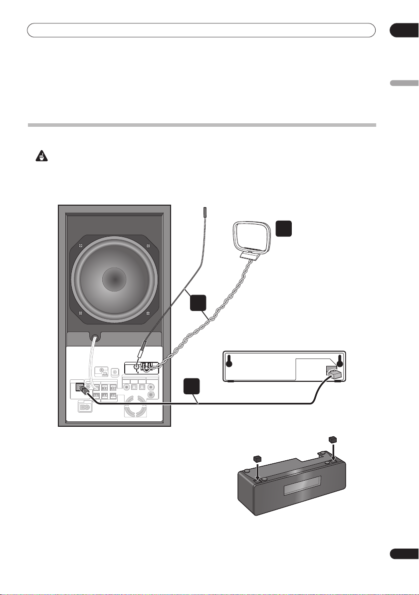
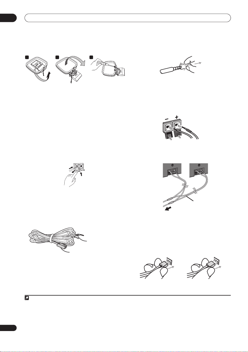
2 Assemble the AM loop antenna.
a b c
a. Bend the stand in the direction indicated by the
arrow.
b. Clip the loop onto the stand.
c. If you want to fix to a wall or other surface, perform
step b after first securing the stand with screws.
It is recommended that you determine the reception
strength before securing the stand with the screws.
3 Connect the AM and FM antennas1.
a. Connect one wire of the AM loop antenna to each AM
antenna terminal
2
.
For each terminal, press down on the tab to open;
insert the wire, then release to secure.
1
2
3
b. Push the FM antenna
FM antenna socket.
4 Connect each speaker.
• The front and surround speaker cables have a color-
coded connector at one end and two bare wires at the
other end.
• Since there is only one terminal to connect the two
center speakers, you will need to use the supplied Y-
cable for the connection.
plug onto the center pin of the
Color-coded wire
(Connect to speaker)
Color-coded connector
(Connect to rear panel)
• Twist and pull off the protective shields on each wire.
• Connect the wires to the speaker. Each speaker in the
illustration can be identified by means of the colorcoded indicator provided on the rear-surface model
label. Match the color-coded wire with the color
indicator on the model label, then insert the colorcoded wire into the red (
into the black (
–
) side.
+
) side and the other wire
• When connecting the center speakers, connect the Ycable dual end to the two center speakers in the
same way.
Y-cable
To Receiver subwoofer
• Connect the other end to the color-coded speaker
terminals on the rear of the receiver subwoofer. Make
sure to insert completely.
The small lug at the wire-end of the speaker plug
should face up or down depending on whether it’s
being plugged into one of the upper or lower speaker
terminals. Please make sure to connect correctly.
Upper terminal Lower terminal
Note
1• Keep antenna cables away from other cables, the display unit and receiver subwoofer.
• If reception with the supplied antenna is poor, see
external antennas
• Do not attach any antenna other than the provided loop antenna, or an external antenna as described on page 27.
2• Don’t let it come into contact with metal objects and avoid placing near computers, television sets or other electrical appliances.
• If radio reception is poor, you may be able improve it by re-inserting each antenna wire into the opposite terminal.
12
En
• For best reception, do not untwist the AM loop antenna wires or wrap them around the loop antenna.
3 To ensure optimum reception, make sure the FM antenna is fully extended and not coiled or hanging at the rear of the unit.
on page 27.
Improving poor FM reception
and
Improving poor AM sound
on page 23 or
Connecting

Connecting up
02
Receiver subwoofer
Surround right
5
MCACC
SETUP MIC
CONTROL IN
SPEAKERS
CONTROL
SYSTEM CONNECTOR
OUT
SUBWOOFER
SURROUND
RL
USE ONLY WITH DISPLAY UNIT.
SEE INSTRUCTION MANUAL.
CENTER FRONT
RL
AC IN
7
• When connections are completed, adjust the cable
placements. If the speakers have been fixed with the
brackets, fix the cable to the groove in the brackets as
shown.
• Fasten the cables together with the spiral wrap.
Hold multiple cables together and place the wrap
over the cables from the end.
Wrap the spiral wrap with the cables in the center.
The spiral wrap may be cut at a desired length.
AM LOOP ANTENNA
FM UNBAL 75
AUDIO INPUT
DIGITAL
ANALOG
DVD
DTV
PC/GAME
AUX
(COAXIAL)
(OPTICAL)
(OPTICAL)
L
4
R
Front right
To AC outlet
(Gray)
Center
(Green)
Listening position
Surround left
(Blue)
Center
(Green)
Y-cable
(Red)
Front left
(White)
Speaker system
5 Connect the subwoofer cable.
• Just below the subwoofer speaker, to the left of
center, you should see the subwoofer connecting
cable. Plug this into the
terminal.
Caution
• These speaker terminals carry
voltage
. To prevent the risk of electric shock when
connecting or disconnecting the speaker cables,
disconnect the power cord before touching any
uninsulated parts.
• Do not connect any speakers other than those
supplied to this system.
• Do not connect the supplied speakers to any
amplifier other than the one supplied with this
system. Connection to any other amplifier may result
in malfunction or fire.
• The center speakers and front/surround speakers are
designed with different impedance values. Be sure to
identify and connect the speakers correctly since
improper connections may result in degraded sound
or operation.
SUBWOOFER SPEAKER
HAZARDOUS LIVE
English
13
En
02
TV
PC/GAME
(OPTICAL)
ITAL
AUDIO INPUT
ANALOG
AUX
R
L
Connecting up
6 If you have a DVD player or other source1
component you want to connect, connect it now before
connecting the power cord in the next step.
See
Connecting auxiliary components
on page 27 for how
to connect a digital source component.
7 Connect the power cord.
2
• Connect the power cord to AC inlet on the receiver
subwoofer. Connect the power cord to a wall socket.
Wall mounting the display unit
It is possibe to mount the display unit on the wall.
Before mounting:
• Remember that the display unit is heavy and could
cause the wood screws to work loose, or the wall
material to fail to support it, resulting in the display
falling. Make sure that the wall you intend to mount
the display on is strong enough to support it. Do not
mount on plywood or soft surface walls.
• Mounting screws are not supplied. Use screws that
are suitable for the wall material and that will support
the weight of the display.
•Pioneer bears no responsibility for accidents resulting
from faulty assembly or installation, insufficient
mounting strength of walls or other building fixtures,
misuse or natural disasters.
• If you are unsure of the qualities and strength of the
wall, consult a professional for advice.
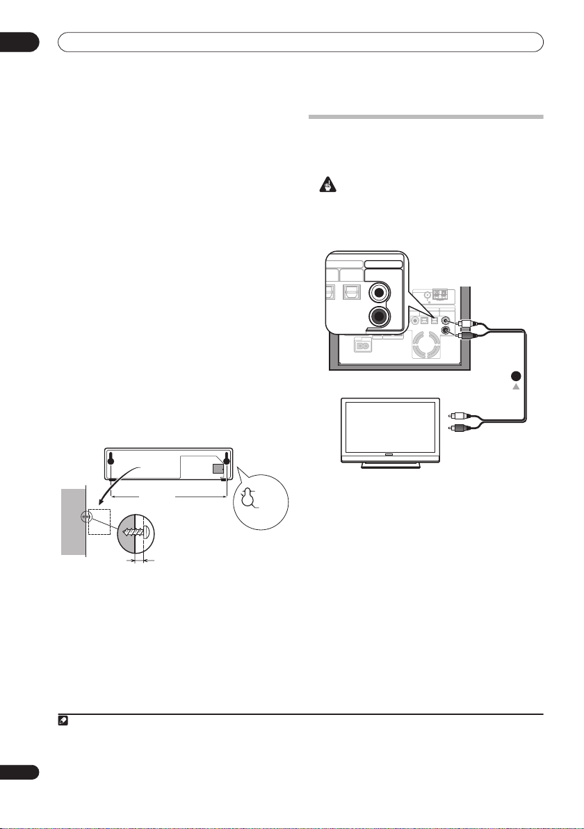
Using this system for TV audio
If your TV has a stereo audio output you can connect it to
this system and enjoy surround TV sound.
Important
• When connecting this system, be sure to switch
power off and disconnect the power cord from the
wall socket. Connect the power cord to the wall
socket only after completing all other connections.
AM LOOP ANTENNA
FM UNBAL 75
MCACC
SETUP MIC
CONTROL IN
AUDIO INPUT
DIGITAL
ANALOG
PC/GAME
DVD
SPEAKERS
SURROUND
RL
RL
DTV
(COAXIAL)
(OPTICAL)
(OPTICAL)
AUX
L
R
To stereo audio outputs
1
SYSTEM CONNECTOR
USE ONLY WITH DISPLAY UNIT.
SEE INSTRUCTION MANUAL.
AC IN
CONTROL
OUT
SUBWOOFER
CENTER FRONT
14
En
TV
7 1/8 in.
(181 mm)
Mounting screw
(not supplied)
5/32 in.
(4 mm)
3/8 in.
(10 mm)
3/32 in. (2.5 mm)
Note
1 Make sure to connect a TV or monitor (for video sources) to take advantage of this system’s home theater potential. Please refer to the
instruction manual supplied with your TV or monitor for connection details.
2• Do not use any power cord other than the one supplied with this system.
• Do not use the supplied power cord for any purpose other than connecting to this system.
1 Connect the audio output jacks on your TV to the
AUX input jacks on the receiver subwoofer.
Use the red/white stereo audio cable (not supplied) for
this connection. Make sure you match the left and right
outputs with their corresponding inputs for correct
stereo sound.
• You can use the
AUX
input jacks for any analog
source you want, such as a tape deck, etc.
Controls and displays
03
Chapter 3
Controls and displays
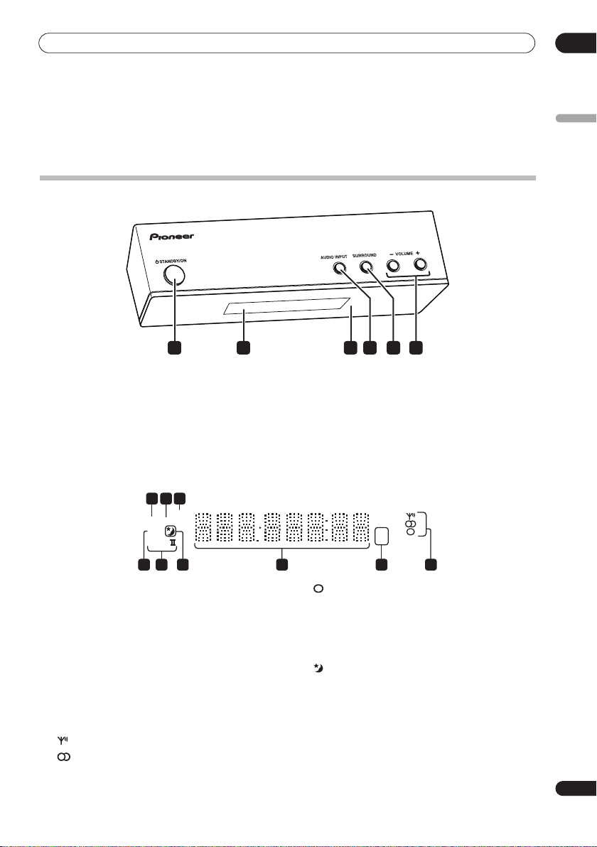
Display unit
1 4 652 3
1
STANDBY/ON
Press to switch the system on/into standby.
2 Front panel display
See below for details.
3 IR remote sensor
(page 17)
Display
2 3
1
SOUND
DTS F.SURR.
2D
2PL
789
1
DTS
Lights during playback of a DTS source (page 20).
2
F.SURR.
Lights when one of the Front Stage Surround
Advance listening modes is selected (page 21).
SURR.
Lights when one of the Advanced Surround listening
modes is selected (page 21).
3 SOUND
Lights when Sound Retriever is active (page 21).
4 Tuner indicators
– Lights when a broadcast is being received.
– Lights when a stereo FM broadcast is being
received in auto stereo mode.
4
AUDIO INPUT (page 27)
Press repeatedly to select one of the external audio
inputs (
DVD, DTV, PC/GAME
5
SURROUND
Use to select a Surround mode (page 20).
6
VOLUME
Use to adjust the volume.
6
– Lights when FM mono reception is selected.
5 kHz / MHz
Indicates the frequency unit shown in the character
display (
kHz
6 Character display
7
Lights when sleep timer is active (page 30).
82 PL II
Lights during Dolby Pro Logic II decoding (page 20).
92 D
Lights during playback of a Dolby Digital source
(page 20).
buttons
for AM,
kHz
MHz
5 4
MHz
for FM).
or
AUX
English
).
15
En

03
RECEIVER
Controls and displays
Remote control
1
STANDBY/ON
2
4
5
7
SETUP
9
10
12
SOUND
RETRIEVER
SURROUND
13
17
1
STANDBY/ON
Press to switch the receiver subwoofer on or into
standby.
2
MUTE
Press to mute all audio from the speakers. Press again to
cancel and restore the sound.
3
VOLUME
Use to adjust the volume.
+/–
MUTE
VOLUME
DVD DT V
ENTER
TUNE
ST
ENTER
TUNE
SOUND
ADVANCED F.S.SURR MCACC
CHANNEL VOLUME
TV
TV CONTROL
RECEIVER
PC/GAME
CLEAR
ST
AUX
TUNER
SLEEP
INPUT
SR
TEST
TONE
3
11
14
15
16
4 Input select buttons
DVD
– Press to select the
DTV
– Press to select the
PC/GAME
(
AUX
– Press to select the PC/game console
PC/GAME
) input.
– Press to select the auxilliary (
DVD
DTV
input.
input.
AUX
) input.
(page 27)
TUNER
– Press to select the built-in radio tuner.
(page 23)
5 Number buttons, CLEAR and ENTER
Use the number buttons for entering radio stations
directly, and so on.
Use
CLEAR
to clear an entry and start again.
Use
ENTER
to confirm an entry.
6
6
8
SLEEP
Press to set the sleep timer (page 30).
7
SETUP
Use to access the menu system for surround sound
setup, tuner settings and so on (page 18, 23, 24, 25, 30).
8 SR+
Use to setup the SR+ features and to select the SR+
mode (page 29).
9
///
(cursor buttons) and
ENTER
Use to navigate the receiver subwoofer menus.
10
SOUND (page 22)
Press to access the sound menu, from which you can
adjust bass and treble, etc.
11
TEST TONE
Use to output the test tone (for speaker setup) (page 26).
12 SOUND RETRIEVER
Press to restore CD quality sound to compressed stereo
audio sources (page 21).
13
SURROUND
Use to select a Surround mode (page 20).
14
ADVANCED
Use to select a Pioneer original surround mode
(page 21).
15
F.S.SURR
Use to select a Front Stage Surround Advance mode
(page 21).
16
MCACC
Starts the Auto MCACC setup (page 18).
17 TV CONTROL
(page 31)
After setting up, use these controls to control your TV.
16
En
Controls and displays
03
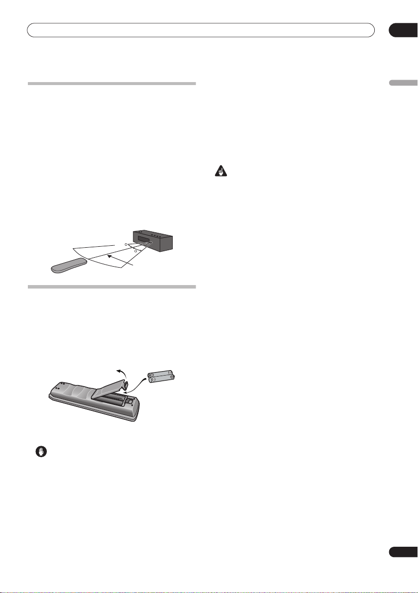
Using the remote control
Please keep in mind the following when using the remote
control:
• Make sure that there are no obstacles between the
remote and the remote sensor on the unit.
• Remote operation may become unreliable if strong
sunlight or fluorescent light is shining on the unit’s
remote sensor.
• Remote controllers for different devices can interfere
with each other. Avoid using remotes for other
equipment located close to this unit.
• Replace the batteries when you notice a fall off in the
operating range of the remote.
• Use within the operating range in front of the remote
control sensor on the display unit, as shown.
30
30
23 ft.
Putting the batteries in the remote
control
1 Open the battery compartment cover on the back of
the remote control.
2 Insert two AA/R6 batteries into the battery
compartment following the indications (
the compartment.
,
) inside
• Make sure that the plus and minus ends of each
battery match the indications in the battery
compartment.
• Remove batteries from equipment that isn’t going to
be used for a month or more.
• When disposing of used batteries, please comply
with governmental regulations or environmental
public instruction’s rules that apply in your country or
area.
WARNING
• Do not use or store batteries in direct sunlight or
other excessively hot place, such as inside a car or
near a heater. This can cause batteries to leak,
overheat, explode or catch fire. It can also reduce the
life or performance of batteries.
English
3 Close the cover.
Caution
Incorrect use of batteries can result in hazards such
as leakage and bursting. Please observe the
following:
• Don’t mix new and old batteries together.
• Don’t use different kinds of battery together —
although they may look similar, different batteries
may have different voltages.
17
En

04
SLEEP
Getting started
Chapter 4
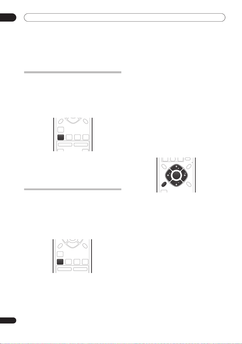
Getting started
System demo setting
Switches the automatic demo feature on or off (this
starts when you plug in for the first time).
ENTER
CLEAR
SETUP
SETUP
ST
ST
SOUND
1Switch the system into standby.
2 Press
SETUP
.
/
3 Use the
(cursor left/right) buttons to select
DEMO from the menu, then press
4 Use the
setting, then press
/
(cursor up/down) buttons to select a
ENTER
Select from:
DEMO ON
•
•
DEMO OFF
– Switches the demo display on.
– Switches the demo display off and the
system into standby.
SR
TUNE
TUNE
ST
ST
ENTER
ENTER
TEST
TONE
TUNE
TUNE
ENTER
.
.
Using the Auto MCACC setup for
optimal surround sound
The Multichannel Acoustic Calibration (MCACC) system
measures the acoustic characteristics of your listening
area, taking into account ambient noise, and testing for
channel delay and channel level. After you have set up
the microphone provided, the system uses the
information from a series of test tones to optimize the
speaker settings and equalization (Acoustic Calibration
EQ) for your particular room.
Important
• The test tones used for Auto MCACC setup are loud;
however, do not turn the volume down during setup
as this may result in a sub-optimal setup.
• Make sure the microphone and speakers are not
moved during the MCACC setup.
STANDBY/ON
STANDBY/ON
MUTE
VOLUME
DVD DTV
PC/GAME
1 Connect the microphone to the MCACC SETUP MIC
jack on the rear panel.
MCACC
SETUP MIC
TUNER
1
ST
ST
ENTER
SOUND
SOUND
RETRIEVER
AUX
CHANNEL
TV
TEST
TONE
TUNE
MCACCADVANCED F.S.SURRSURROUND
MCACC
VOLUME
INPUT
CONTROL
SYSTEM CONNECTOR
OUT
USE ONLY WITH DISPLAY UNIT.
SEE INSTRUCTION MANUAL.
AC IN
Note
1 You only need to use the Auto MCACC setup once (unless you change the placement of your speakers or your room layout).
18
En
MCACC
SETUP MIC
SUBWOOFER
CENTER FRONT
SPEAKERS
RL
RL
SURROUND
L
R
AM LOOP ANTENNA
FM UNBAL 75
CONTROL IN
AUDIO INPUT
DIGITAL
ANALOG
PC/GAME
DVD
DTV
AUX
(COAXIAL)
(OPTICAL)
(OPTICAL)

Getting started
04
2 Place the microphone at your normal listening
position.
Place the mic horizontally about ear level at your normal
listening position using a table or chair.
Make sure there are no obstacles between the speakers
and the microphone.
3 If the receiver subwoofer is off, press
ON
to turn the power on.
4 Press
MCACC
.
Try to be as quiet as possible after pressing
STANDBY/
MCACC
. The
volume increases automatically and the system outputs
a series of test tones.
• To cancel Auto MCACC setup before it has finished,
press
MCACC
. The unit will continue to use the
previous settings.
• If the ambient noise level is too high,
the display for five seconds. To exit and check the
noise levels
ENTER
• If you see an
when
1
, press
MCACC
RETRY
shows in the display.
ERR MIC
or
ERR SP
NOISY
blinks in
, or to try again, press
message in the
display, there may be a problem with your mic or the
speaker connections. To try again, press
when you see
RETRY
2
.
ENTER
When the MCACC setup is complete, the volume level
returns to normal,
Acoustic Calibration EQ is activated.
COMPLETE3 shows in the display, and
4
English
Note
1• If the room environment is not optimal for the Auto MCACC setup (too much ambient noise, echo off the walls, obstacles blocking the speakers from
the microphone) the final settings may be incorrect. Check for household appliances (air conditioner, fridge, fan, etc.), that may be affecting the
environment and switch them off if necessary.
• Some older TVs may interfere with the operation of the mic. If this seems to be happening, switch off the TV during Auto MCACC setup.
2 If this doesn’t work, press
3 If
COMPLETE
4 See
Listening with Acoustic Calibration EQ
MCACC
doesn’t appear, it is likely an error occurred during the setup. Please check all connections and try again.
, turn off the power, and check the problem indicated by the
on page 22 to switch on/off Acoustic Calibration EQ.
ERR
message, then try the Auto MCACC setup again.
19
En
SOUND
TONE
05
Listening to your system
Chapter 5
Listening to your system
Auto listening mode
The Auto listening mode is the simplest way to listen to
any source as it was mastered: the output from the
speakers mirrors the channels in the source material.
If you set up the system for Front surround (page 7), the
Front Surround modes will give the best results (see
Using Front Stage Surround Advance
SOUND
RETRIEVER
SURROUND
CHANNEL
TV
• Press
SURROUND
to select the AUTO listening
mode.
If the source is Dolby Digital or DTS, the front panel 2 D
or
DTS
indicator lights.
• You can also use the
SURROUND
display unit to change the listening mode.
Listening in surround sound
You can listen to stereo or multichannel sources in
surround sound. Surround sound is generated from
stereo sources using one of the Dolby Pro Logic
decoding modes.
If you set up the system for Front surround (page 7), the
Front Surround modes will give the best results (see
Using Front Stage Surround Advance
SOUND
SOUND
RETRIEVER
SURROUND
CHANNEL
• Press
SURROUND
mode.
• You can also use the
display unit to change the listening mode.
The choices that appear in the display will vary according
to the type of source that’s playing.
If the source is Dolby Digital or DTS, the front panel
or
DTS
indicator lights.
20
En
repeatedly to select a listening
SURROUND
TUNE
TUNE
on page 21).
MCACCADVANCED F.S.SURRSURROUND
VOLUME
INPUT
on page 21).
TEST
TONE
MCACCADVANCED F.S.SURRSURROUND
VOLUME
button on the
button on the
Dolby Pro Logic II Music settings
When listening in Dolby Pro Logic II Music mode (see
above), there are three settings you can adjust: Center
Width, Dimension, and Panorama.
1With Dolby Pro Logic II Music mode active, press
SOUND
2 Use
DIMEN. or PANORAMA then press
3 Use
then press
2
D
•
AUTO
– Auto listening mode (see above)
•
DOLBY PL
(Dolby Pro Logic) – 4.1 channel surround
sound for use with any two-channel source
MOVIE
(Dolby Pro Logic II Movie) – 5.1 channel
•
surround sound, especially suited to movie sources,
for use with any two-channel source
•
MUSIC
(Dolby Pro Logic II Music) – 5.1 channel
surround sound, especially suited to music sources,
for use with any two-channel source; see
Logic II Music settings
STEREO
•
– See
below
Listening in stereo
ENTER
SOUND
RETRIEVER
CLEAR
TUNE
TUNE
ST
ST
ST
ST
ENTER
ENTER
TUNE
TUNE
SETUP
SOUND
SOUND
TEST
TONE
Dolby Pro
on page 21
SR
.
/
•
C WIDTH
(cursor left/right) to select C WIDTH,
(Center Width) – Provides a better blend of
ENTER
.
the front speakers by spreading the center channel
between the front right and left speakers, making it
sound wider (higher settings) or narrower (lower
settings)
•
DIMEN.
(Dimension) – Adjusts the depth of the
surround sound balance from front to back, making
the sound more distant (minus settings), or more
forward (positive settings)
•
PANORAMA
– Extends the front strereo image to
include the surround speakers for a ‘wraparound’
effect.
/
(cursor up/down) to adjust the setting
ENTER
to confirm.
Listening to your system
TUNE
Using Front Stage Surround Advance
The Front Stage Surround Advance modes are effective
when you are using the Front surround speaker setup as
described on page 7.
ST
ST
ENTER
SOUND
SOUND
RETRIEVER
CHANNEL
TV
• Press F.S.SURR to select a Front Stage Surround
Advance mode.
Press repeatedly to select
EXTRAPWR
•
FOCUS5.1
.
– Use to provide a rich surround sound
effect directed to the center area where the left and
right speakers’ sound projection converges.
•
WIDE5.1
– Use to provide a surround sound effect to
a wider area than
EXTRAPWR
•
FOCUS5.1
– Outputs stereo sound (in the case of
multi-channel sources, down-mixed stereo sound)
from the surround speakers for powerful stereo
effect.
TEST
TONE
TUNE
MCACCADVANCED F.S.SURRSURROUND
F.S. SURR
VOLUME
INPUT
FOCUS5.1, WIDE5.1
mode.
or
•
TV SURR.
– Surround sound for mono or stereo TV
broadcasts
SPORTS
•
•
•
•
– Suitable for sports programming
ADV.GAME
VIRTUAL
subwoofer and front speakers.
X-STEREO
music sources
– Suitable for TV game units
– A virtual surround effect using just the
– Powerful surround sound for stereo
Listening in stereo
You can listen to any source—stereo or multichannel—in
stereo. When playing a multichannel source, all
channels are downmixed to the front left/right speakers
and the subwoofer.
ST
ST
ENTER
SOUND
SOUND
RETRIEVER
SURROUND
CHANNEL
TV
• Press
SURROUND
repeatedly until STEREO shows in
the display.
• You can also use the
SURROUND
display unit to change the listening mode.
TEST
TONE
TUNE
MCACCADVANCED F.S.SURRSURROUND
VOLUME
INPUT
button on the
05
English
Using Advanced Surround
The Advanced Surround effects can be used with any
multichannel or stereo source for a variety of additional
surround sound effects. These modes are designed to
provide optimum listening effect when using the
Standard surround setup described on page 9.
ST
ST
ENTER
SOUND
SOUND
RETRIEVER
CHANNEL
TV
• Press
ADVANCED
to select an Advanced Surround
mode.
Press repeatedly to select:
•
ACTION
– Suitable for action movies
UNPLUGED
•
•
EXPANDED
– Suitable for acoustic musical sources
– Wide sound field
ADVANCED
TEST
TONE
TUNE
MCACCADVANCED F.S.SURRSURROUND
VOLUME
INPUT
Using the Sound Retriever
When audio data is removed during the MP3 or WMA
compression process, sound quality often suffers from
an uneven sound image. The Sound Retriever feature
employs new DSP technology that helps bring CD quality
sound back to compressed 2-channel audio by restoring
sound pressure and smoothing jagged artifacts left over
after compression.
ST
ST
ENTER
SOUND
SOUND
SOUND
RETRIEVER
RETRIEVER
•While listening to a stereo source, press
RETRIEVER
.
Press repeatedly to switch between:
RTRV ON
•
•
— Switches the Sound Retriever on.
RTRV OFF
— Switches the Sound Retriever off.
TEST
TONE
TUNE
MCACCADVANCED F.S.SURRSURROUND
SOUND
21
En
 Loading...