


GM-9127-ZT

PIONEER CORPORATION 4-1, Meguro 1-Chome, Meguro-ku, Tokyo 153-8654, Japan
PIONEER ELECTRONICS (USA) INC. P.O.Box 1760, Long Beach, CA 90801-1760 U.S.A.
PIONEER EUROPE NV Haven 1087 Keetberglaan 1, 9120 Melsele, Belgium
PIONEER ELECTRONICS ASIACENTRE PTE.LTD. 253 Alexandra Road, #04-01, Singapore 159936
C PIONEER CORPORATION 2002
K-ZZB. JULY 2002 Printed in Japan
ORDER NO.
CRT2884
POWER AMPLIFIER
GM-9127ZT/EW
TOYOTA
VEHICLE DESTINATION PRODUCED AFTER TOYOTA PART No. ID No. PIONEER MODEL No.
LAND CRUISER Europe August 2002 86280-60340 GM-9127ZT/EW
GM-9127ZT-91/EW
LAND CRUISER Any country or area August 2002 86280-60320 GM-9227ZT/E
except for Japan GM-9227ZT-91/E
GM-9127ZT-91/EW
GM-9227
ZT/E
GM-9227ZT-91/E
GM-9127ZT/EW
For details, refer to "Important symbols for good services".
2
1
234
12
34
F
E
D
C
B
A
GM-9127ZT/EW
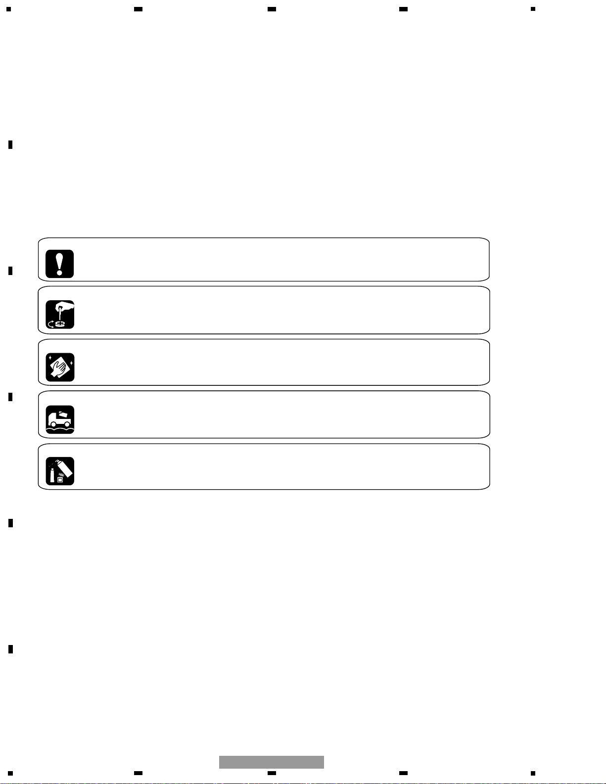
[ Important symbols for good services ]
In this manual, the symbols shown-below indicate that adjustments, settings or cleaning should be made securely.
When you find the procedures bearing any of the symbols, be sure to fulfill them:
2. Adjustments
To keep the original performances of the product, optimum adjustments or specification confirmation is indispensable.
In accordance with the procedures or instructions described in this manual, adjustments should be performed.
3. Cleaning
For optical pickups, tape-deck heads, lenses and mirrors used in projection monitors, and other parts requiring cleaning,
proper cleaning should be performed to restore their performances.
5. Lubricants, glues, and replacement parts
Appropriately applying grease or glue can maintain the product performances. But improper lubrication or applying
glue may lead to failures or troubles in the product. By following the instructions in this manual, be sure to apply the
prescribed grease or glue to proper portions by the appropriate amount.For replacement parts or tools, the prescribed
ones should be used.
4. Shipping mode and shipping screws
To protect the product from damages or failures that may be caused during transit, the shipping mode should be set or
the shipping screws should be installed before shipping out in accordance with this manual, if necessary.
1. Product safety
You should conform to the regulations governing the product (safety, radio and noise, and other regulations), and
should keep the safety during servicing by following the safety instructions described in this manual.
SAFETY INFORMATION
This service manual is intended for qualified service technicians; it is not meant for the casual do-it-yourselfer.
Qualified technicians have the necessary test equipment and tools, and have been trained to properly and safely repair
complex products such as those covered by this manual.
Improperly performed repairs can adversely affect the safety and reliability of the product and may void the warranty.
If you are not qualified to perform the repair of this product properly and safely, you should not risk trying to do so
and refer the repair to a qualified service technician.
3
5
6
7
8
F
E
D
C
B
A
5
6
7
8
GM-9127ZT/EW
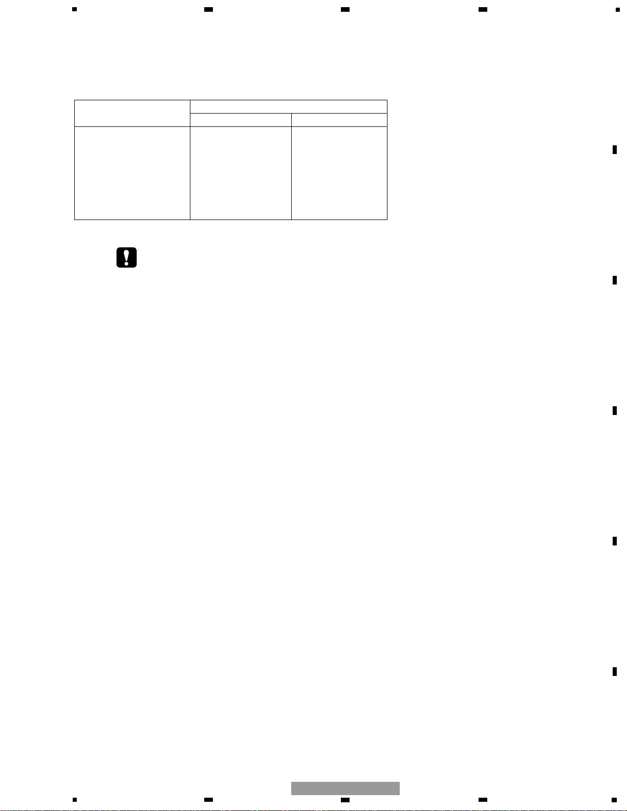
NOTE:
- When diagnosing a product, take care of its heated portion.
Power IC (IC801,802,803)
Power Supply IC (IC901,902)
DSP IC (IC201,251)
Heat Sink
IC Holder
- Supplementally model is identical to the original except for the addition of following items.
Part No.
Description GM-9127ZT-91/EW GM-9227ZT-91/E
Cover CEG1057 CEG1045
Polyethylene Bag Not used CEG1185
Protector CHP2329 Not used
Protector CHP2330 Not used
Carton CHG4144 CHG4865
Contain Box CHL4863 CHL4866
CONTENTS
SAFETY INFORMATION............................................2
1. SPECIFICATIONS .......................................................3
2. EXPLODED VIEWS AND PARTS LIST ......................4
3. BLOCK DIAGRAM AND SCHEMATIC DIAGRAM ....6
4. PCB CONNECTION DIAGRAM................................14
5. ELECTRICAL PARTS LIST........................................22
6. ADJUSTMENT.........................................................27
7. GENERAL INFORMATION.......................................33
7.1 DIAGNOSIS .......................................................33
7.1.1 DISASSEMBLY.........................................33
7.1.2 CONNECTOR FUNCTION DESCRIPTION ......36
7.2 IC ........................................................................37
7.3 EXPLANATION...................................................38
7.3.1 OPERATIONAL FLOW CHART .................38
7.3.2 SYSTEM BLOCK DIAGRAM.....................40
8. OPERATIONS ...........................................................41
1. SPECIFICATIONS
Power source . . . . . . . . . . . . .13.2±0.1V(10.5-16.0V)
Grounding . . . . . . . . . . . . . . . .Negative type
Backup current . . . . . . . . . . . .1.0mA or less
Dimensions(No Bracket) . . . .210mm(W)x60mm(H)x150mm(D)
Weight(GM-9127ZT/EW) . . . .1.985kg
(GM-9227ZT/E) . . . . . .2.086kg
Maximum output power . . . .22W or more(Front)
22W or more(Rear)
22W or more(Woofer)
4
1
234
12
34
F
E
D
C
B
A
GM-9127ZT/EW
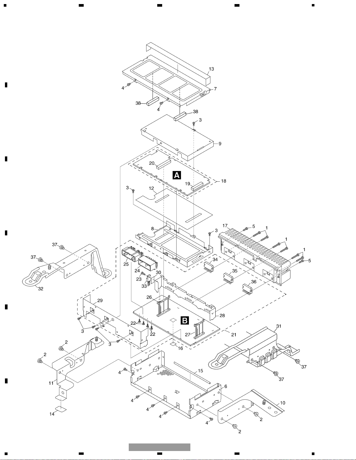
2. EXPLODED VIEWS AND PARTS LIST
2.1 EXTERIOR

5
5
6
7
8
F
E
D
C
B
A
5
6
7
8
GM-9127ZT/EW
1 Screw BMZ30P200FMC
2 Screw(GM-9127ZT/EW) BMZ50P060FMC
3 Screw BSZ26P060FMC
4 Screw BSZ30P060FMC
5 Screw BSZ30P100FMC
6 Chassis CNA2142
7 Case CNB2563
8 Shield Case CNC8185
9 Shield Case CNC8186
10 Bracket(GM-9127ZT/EW) CNC8919
11 Bracket(GM-9127ZT/EW) CNC8920
12 Insulator CNM6145
13 Seal CNM6686
14 Cushion(GM-9127ZT/EW) CNM7009
15 Seal CNM7170
16 Seal CNM7305
17 Heat Sink CNR1566
18 DSP Unit CWM8080
19 Socket(CN102) CKS3632
20 Socket(CN101) CKS4241
21 Amp Unit CWM8081
22 Screw BPZ30P060FSN
23 Screw BSZ26P080FMC
24 Connector(CN902) CKM1308
25 Connector(CN901) CKM1310
26 Plug(CN906) CKS4240
27 Plug(CN905) CKS4242
28 Holder CNC8187
29 Bracket CNC8681
30 Sheet CNM7015
31 Bracket(GM-9227ZT/E) CND1093
32 Holder(GM-9227ZT/E) CND1355
33 IC(IC902) BA178M05T
34 IC(IC801) PAL006A
35 IC(IC802) PAL006A
36 IC(IC803) PAL006A
37 Screw(GM-9227ZT/E) BMZ50P060FMC
38 Cushion CNM7756
NOTE:
- Parts marked by “*” are generally unavailable because they are not in our Master Spare Parts List.
- Screws adjacent to ∇ mark on the product are used for disassembly.
- For the applying amount of lubricants or glue, follow the instructions in this manual.
( In the case of no amount instructions, apply as you think it appropriate.)
- EXTERIOR SECTION PARTS LIST
Mark No. Description Part No.
Mark No. Description Part No.
6
1
234
12
34
F
E
D
C
B
A
GM-9127ZT/EW
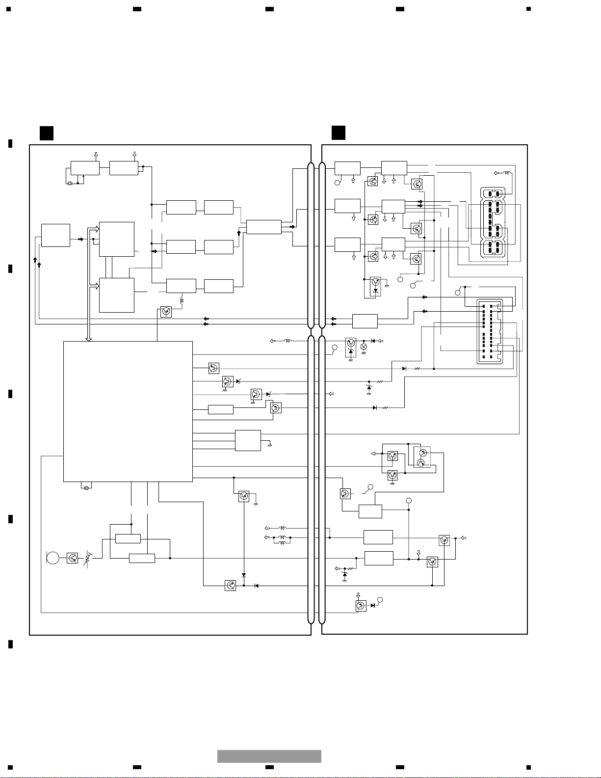
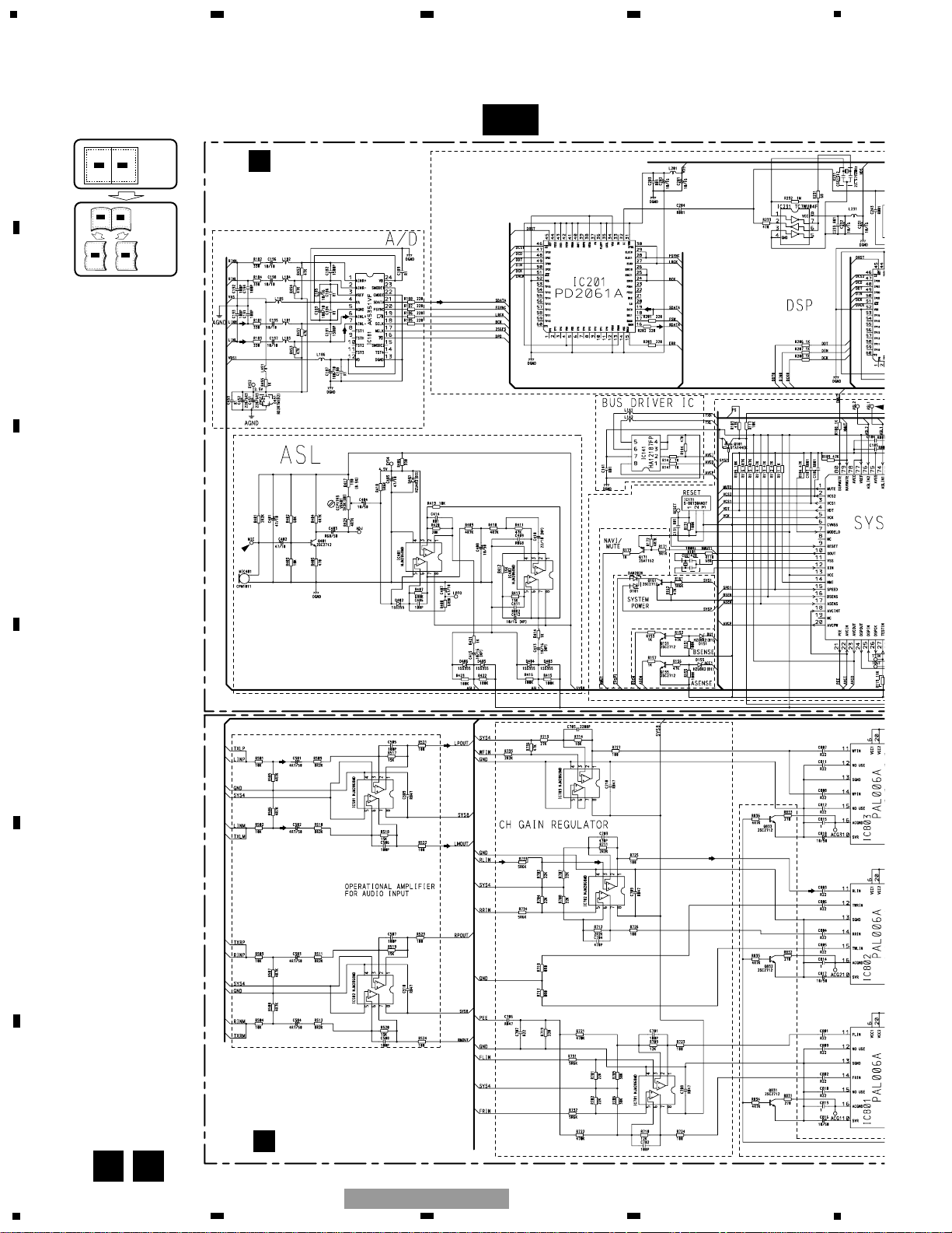
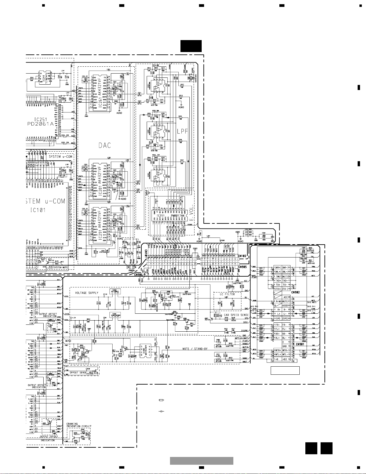
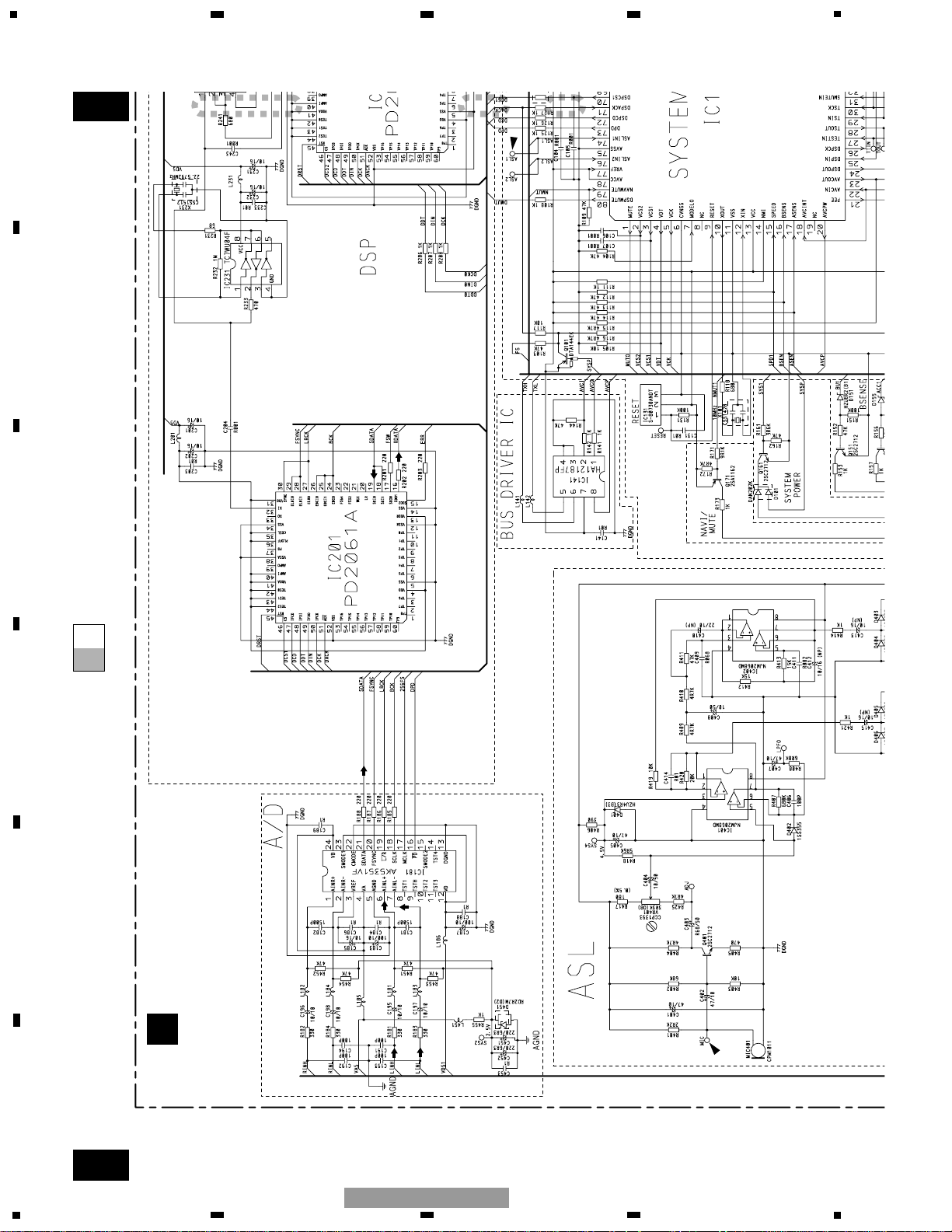
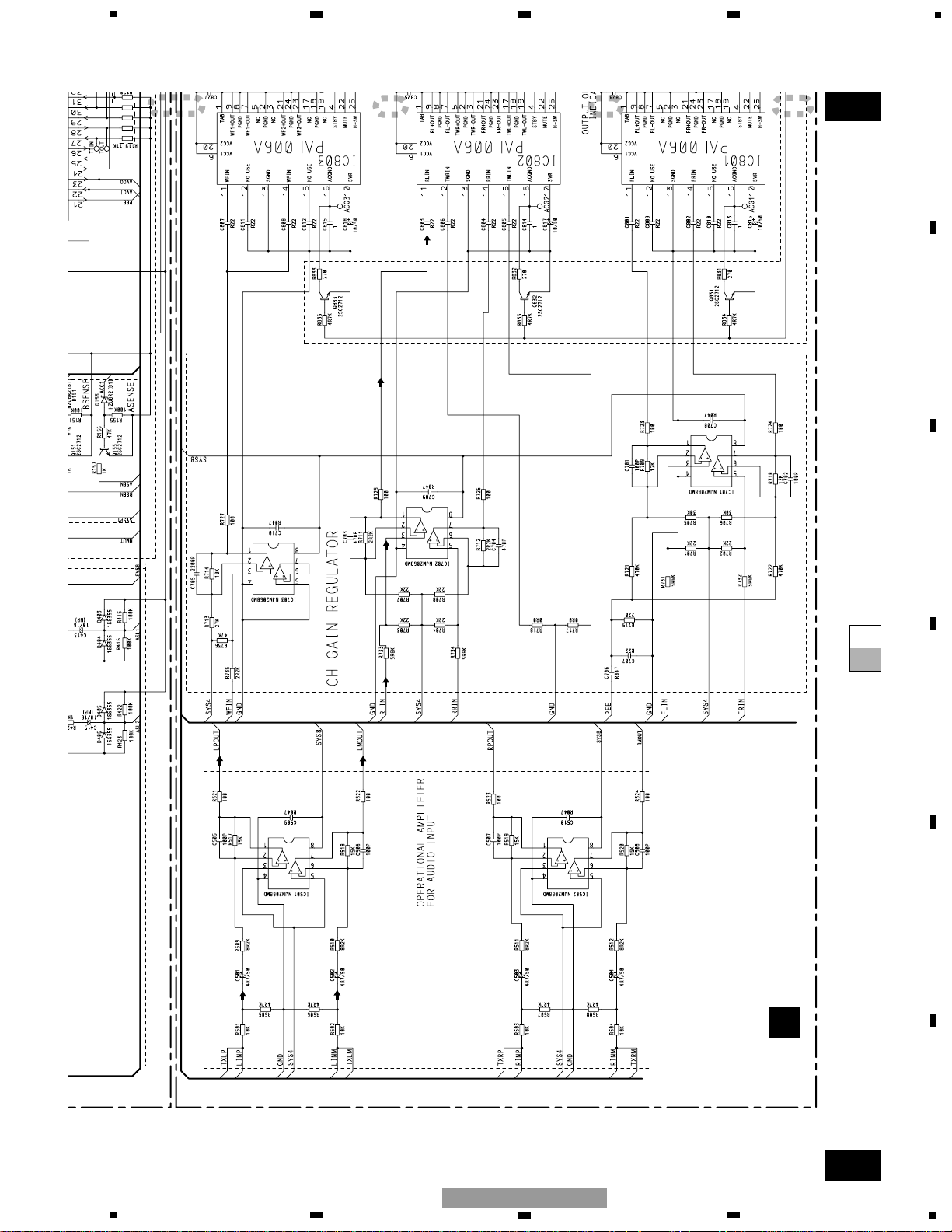
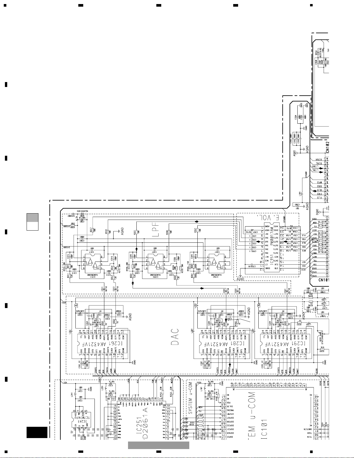
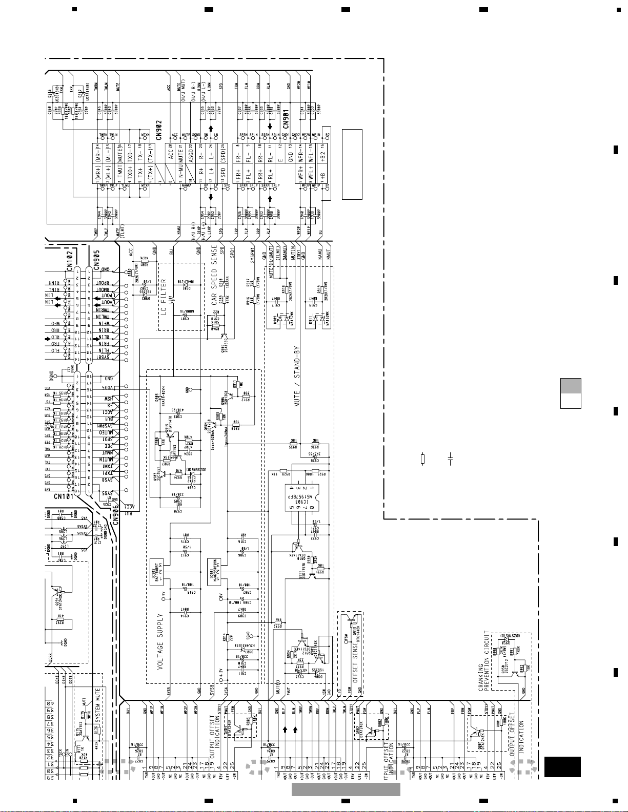
3. BLOCK DIAGRAM AND SCHEMATIC DIAGRAM
3.1 BLOCK DIAGRAM
13
11
9
6
13
11
9
6
3
6
9
8
13
7
16
13
10
11
12
6
7
12
IC251
PD2061A
IC181
AK5351VF
IC261
AK4321VF
IC351
PM0017AM
IC101
IC131
S-80730ANDT
IC902
BA178M05T
IC901
NJM2930F08K
Q904
Q906
Q912
Q909
Q903
5V REGULATOR
8V REGULATOR
SYSTEM
POWER SWITCH
5V REGULATOR
AUDIO INPUT
BUFFER
INPUT
CONNECTOR
OUTPUT
CONNECTOR
IC501
NJM2068MD
IC903
M51957BFP
IC703
NJM2068MD
IC803
PAL006A
SUB WOOFER
POWER AMP
SUB WOOFER
OPE AMP
REAR
POWER AMP
FRONT
POWER AMP
FRONT-L
OPE AMP
REAR-L
OPE AMP
IC701
NJM2068MD
IC702
NJM2068MD
P
PEE
3
1
11
9
7
7
9
4
11
1
3
2
1
11
7
9
2
7
6
1
7
2
6
1
3
1
3
SYS4
BU
STBY1
BU1
BU1
BU
L901
B.U
WFL-
WFL+
IC802
PAL006A
IC801
PAL006A
RL-
RL+
FL+
FL-
CN901
L-
L+
TMUT
MUTE
(H/U MUT)
ACC
Q915
6
7
18
A/D
ACC1
ACC1
BU1
ASENS
BSENS
Q155
Q151
17
16
N-MU
NMUT
Q171
NAVIMUTE
79
RESET
1
RESET
9
2
SYSTEM CONTROLLER
SYSPW1
SYSPW1
SYS5SYSD5
1
18
17
2
SYSA5
AVDD
DVDD
16
3
SYS8
SYS8
Q161
SYSPW1
66
Q910
Q911
2
4
STBY1
4
25
25
25
Q801
Q802
Q803
PMUT
MUTEO
MUTO
1
MUTE
MUTIN
MUTI
Q175
31
SMUTEIN
Q913
PWSENS
65
MUTE
/STBY
MUTE
VDD5VDD5
VDD
P
PEE
11
8
PEE
21
NMUT1
NAVI/MUTE
ACC SENSE
BACK UP SENSE
SYSTEM MUTE
PEE
SYSP1
CN906
CN101
CN905
CN102
FS
FS
5
14
A
A
B
B
CN902
ELECTRONIC
VOLUME
IC401
NJM2068MD
Q401
MIC
MIC401
VR401
3
ASLIN2
76
1
ASLIN1
74
IC402
NJM2068MD
5
7
ASL
8
8
IC141
HA12187FP
BUS DRIVER
AVCIN
AVCOUT
AVCPW
22
23
20
2
1
8
7
15 4
DSP
DSP
10
12
XOUT
XIN
21
IC281
AK4321VF
IC291
AK4321VF
IC311
NJM2068MD
IC331
NJM2068MD
IC341
NJM2068MD
FRONT DAC
IC231
TC7WU04F
IC241
TC7W74FU
1
7
CRYSTAL
OSCILLATOR
REAR DAC
WOOFER DAC
FRONT LPF
REAR LPF
WOOFER LPF
16
8
3
18
1
5
17 15
19 18
16
15
8
8
3
18
3
18
3
1
1
7
20
RLO
RLIN
22
FLO
FLIN
18
WFO
WFIN
(ML-)
(ML+)
17
19
(TWLP)
(TWLP)
(TWLM)
(TWLM)
(RLM)
(RLP)
(FLM)
(FLP)
AINL+
AINL-
SDATA
SDI1
SDO1
SDO0
SDO2
SDI0
SDI1
SDO1
SDO2
(FDATA)
(WDATA )
(RDATA )
VCC
8
VCC
8
3
1
2
2
3
5
5
5
(256FS)
CK
D
q
XTI
SDATA
AOUTL
XTI
SDATA
AOUTL
XTI
SDATA
AOUTL
IN1
IN3
IN5
OUT3
OUT1
OUT5
(FSW)
(FSW)
Q833
Q832
Q831
10
10
10
Q950
B
A
DSP UNIT
AMP UNIT
5
5
19
SDI0
Q291
68
DSPERR
17
AOUTR
6
SYS4
6
SYS4
6
SYS4
22
PMUT
STBY1
STBY1
22
PMUT
22
PMUT
Q101
(ASL1)
(ASL2)
SPD
(SPD)
C
(SPD)
C
Q907
10
9
SPD1SPD1
SPEED SENSOR PULSE
15
SPEED
BU
IC201
PD2061A
6 TXH TXP1
TX+
OFFSET SENSE
PD5724B

7
5
6
7
8
F
E
D
C
B
A
5
6
7
8
GM-9127ZT/EW
8
1
234
12
34
F
E
D
C
B
A
GM-9127ZT/EW
A-aA-a A-b A-b
A-a
A-b
A-b
A-a
Large size
SCH diagram
Guide page
Detailed page
Note: When ordering service parts, be sure to refer to " EXPLODED VIEWS AND PARTS LIST" or
"ELECTRICAL PARTS LIST".
A-a
A
B
A
DSP UNIT
B
AMP UNIT
POWER AM
-12.8dBs
-20.0dBs
3.2 SCHEMATIC DIAGRAM (GUIDE PAGE)
9
5
6
7
8
F
E
D
C
B
A
5
6
7
8
GM-9127ZT/EW
A-b
A B
PD5724B
Decimal points for resistor
and capacitor fixed values
are expressed as :
2.2 2R2
0.022 R022
←
←
Symbol indicates a resistor.
No differentiation is made between chip resistors and
discrete resistors.
NOTE :
Symbol indicates a capacitor.
No differentiation is made between chip capacitors and
discrete capacitors.
-11.8dBs
+13.2dBs
-26.4dBs
-19.2dBs
-14.2dBs
CD 1kHz -20dB PLAY
(VOL:MAX, TONE:FLAT)
10
1
234
12
34
F
E
D
C
B
A
GM-9127ZT/EW
A-a
A-b
A-a
A-a
A-b
1
2 3
PD572
A
DSP UNIT
11
5
6
7
8
F
E
D
C
B
A
5
6
7
8
GM-9127ZT/EW
A-a
A-b
A-a
A-a
A-b
4
5 6
7
B
AMP UNIT
POWER AMP
-12.8dBs
-20.0dBs
12
1
234
12
34
F
E
D
C
B
A
GM-9127ZT/EW
A-a
A-b
A-b
1
2 3
-26.4dBs
-19.2dBs
-14.2dBs
13
5
6
7
8
F
E
D
C
B
A
5
6
7
8
GM-9127ZT/EW
A-a
A-b
A-b
4
5 6
7
Decimal points for resistor
and capacitor fixed values
are expressed as :
2.2 2R2
0.022 R022
←
←
Symbol indicates a resistor.
No differentiation is made between chip resistors and
discrete resistors.
NOTE :
Symbol indicates a capacitor.
No differentiation is made between chip capacitors and
discrete capacitors.
-11.8dBs
+13.2dBs
CD 1kHz -20dB PLAY
(VOL:MAX, TONE:FLAT)
 Loading...