


VSX-21TXH
Table of contents
 Loading...
Operating Instructions
audio/video multi-channel receiver
FEDERAL COMMUNICATIONS COMMISSION DECLARATION OF CONFORMITY
This device complies with part 15 of the FCC Rules. Operation is subject to the following two conditions: (1) This
device may not cause harmful interference, and (2) this device must accept any interference received, including
interference that may cause undesired operation.
Product Name: AUDIO/VIDEO MULTI-CHANNEL RECEIVER
Model Number: VSX-23TXH, VSX-21TXH
Responsible Party Name: PIONEER ELECTRONICS SERVICE, INC.
Address: 1925 E. DOMINGUEZ ST. LONG BEACH, CA 90801-1760, U.S.A.
Phone: 1-800-421-1404
IMPORTANT NOTICE
THE SERIAL NUMBER FOR THIS EQUIPMENT IS LOCATED IN THE REAR.
PLEASE WRITE THIS SERIAL NUMBER ON YOUR ENCLOSED WARRANTY CARD AND KEEP IN A SECURE AREA.
THIS IS FOR YOUR SECURITY.
D1-4-2-6-1*_A1_En
NOTE:
This equipment has been tested and found to comply with the limits for a Class B digital device, pursuant to Part 15
of the FCC Rules. These limits are designed to provide reasonable protection against harmful interference in a
residential installation. This equipment generates, uses, and can radiate radio frequency energy and, if not installed
and used in accordance with the instructions, may cause harmful interference to radio communications. However,
there is no guarantee that interference will not occur in a particular installation. If this equipment does cause
harmful interference to radio or television reception, which can be determined by turning the equipment off and on,
the user is encouraged to try to correct the interference by one or more of the following measures:
— Reorient or relocate the receiving antenna.
— Increase the separation between the equipment and receiver.
— Connect the equipment into an outlet on a circuit different from that to which the receiver is connected.
— Consult the dealer or an experienced radio/TV technician for help.
D8-10-1-2_A1_En
This Class B digital apparatus complies with
Canadian ICES-003.
D8-10-1-3_A1_En
Information to User
Alterations or modifications carried out without
appropriate authorization may invalidate the user’s
right to operate the equipment.
D8-10-2_A1_En
CAUTION
This product satisfies FCC regulations when shielded
cables and connectors are used to connect the unit
to other equipment. To prevent electromagnetic
interference with electric appliances such as radios
and televisions, use shielded cables and connectors
for connections.
D8-10-3a_A1_En
WARNING
This equipment is not waterproof. To prevent a fire
or shock hazard, do not place any container filled
with liquid near this equipment (such as a vase or
flower pot) or expose it to dripping, splashing, rain
or moisture.
D3-4-2-1-3_B_En
WARNING
The voltage of the available power supply differs
according to country or region. Be sure that the
power supply voltage of the area where this unit
will be used meets the required voltage (e.g., 230 V
or 120 V) written on the rear panel.
D3-4-2-1-4_A_En
Before plugging in for the first time, read the following
section carefully.
This product is for general household purposes. Any
failure due to use for other than household purposes
(such as long-term use for business purposes in a
restaurant or use in a car or ship) and which requires
repair will be charged for even during the warranty
period.
K041_En
CAUTION
To prevent fire hazard, the Class 2 Wiring Cable
should be used for connection with speaker, and
should be routed away from hazards to avoid
damage to the insulation of the cable.
The exclamation point within an equilateral
triangle is intended to alert the user to the
presence of important operating and
maintenance (servicing) instructions in the
literature accompanying the appliance.
The lightning flash with arrowhead symbol,
within an equilateral triangle, is intended to
alert the user to the presence of uninsulated
“dangerous voltage” within the product’s
enclosure that may be of sufficient
magnitude to constitute a risk of electric
shock to persons.
CAUTION:
TO PREVENT THE RISK OF ELECTRIC
SHOCK, DO NOT REMOVE COVER (OR
BACK). NO USER-SERVICEABLE PARTS
INSIDE. REFER SERVICING TO QUALIFIED
SERVICE PERSONNEL.
CAUTION
RISK OF ELECTRIC SHOCK
DO NOT OPEN
IMPORTANT
D3-4-2-1-1_A1_En
Read these instructions.
Keep these instructions.
Heed all warnings.
Follow all instructions.
Do not use this apparatus near water.
Clean only with dry cloth.
Do not block any ventilation openings. Install in
accordance with the manufacturer’s instructions.
Do not install near any heat sources such as
radiators, heat registers, stoves, or other apparatus
(including amplifiers) that produce heat.
Do not defeat the safety purpose of the polarized or
grounding-type plug. A polarized plug has two
blades with one wider than the other. A grounding
type plug has two blades and a third grounding
prong. The wide blade or the third prong are
provided for your safety. If the provided plug does
not fit into your outlet, consult an electrician for
replacement of the obsolete outlet.
Protect the power cord from being walked on or
pinched particularly at plugs, convenience
receptacles, and the point where they exit from the
apparatus.
1)
2)
3)
4)
5)
6)
7)
8)
9)
10)
Only use attachments/accessories specified by the
manufacturer.
Use only with the cart, stand, tripod, bracket, or
table specified by the manufacturer, or sold with the
apparatus. When a cart is used, use caution when
moving the cart/apparatus combination to avoid
injury from tip-over.
Unplug this apparatus during lightning storms or
when unused for long periods of time.
Refer all servicing to qualified service personnel.
Servicing is required when the apparatus has been
damaged in any way, such as power-supply cord or
plug is damaged, liquid has been spilled or objects
have fallen into the apparatus, the apparatus has
been exposed to rain or moisture, does not operate
normally, or has been dropped.
P1-4-2-2_En
11)
12)
13)
14)
WARNING
To prevent a fire hazard, do not place any naked
flame sources (such as a lighted candle) on the
equipment.
D3-4-2-1-7a_A_En
VENTILATION CAUTION
When installing this unit, make sure to leave space
around the unit for ventilation to improve heat
radiation (at least 60 cm at top, 10 cm at rear, and
30 cm at each side).
WARNING
Slots and openings in the cabinet are provided for
ventilation to ensure reliable operation of the
product, and to protect it from overheating. To
prevent fire hazard, the openings should never be
blocked or covered with items (such as newspapers,
table-cloths, curtains) or by operating the
equipment on thick carpet or a bed.
D3-4-2-1-7b_A_En
Operating Environment
Operating environment temperature and humidity:
+5 °C to +35 °C (+41 °F to +95 °F); less than 85 %RH
(cooling vents not blocked)
Do not install this unit in a poorly ventilated area, or in
locations exposed to high humidity or direct sunlight (or
strong artificial light)
D3-4-2-1-7c*_A1_En

If the AC plug of this unit does not match the AC
outlet you want to use, the plug must be removed
and appropriate one fitted. Replacement and
mounting of an AC plug on the power supply cord of
this unit should be performed only by qualified
service personnel. If connected to an AC outlet, the
cut-off plug can cause severe electrical shock. Make
sure it is properly disposed of after removal.
The equipment should be disconnected by removing
the mains plug from the wall socket when left unused
for a long period of time (for example, when on
vacation).
D3-4-2-2-1a_A1_En
CAUTION
The STANDBY/ON switch on this unit will not
completely shut off all power from the AC outlet.
Since the power cord serves as the main disconnect
device for the unit, you will need to unplug it from
the AC outlet to shut down all power. Therefore,
make sure the unit has been installed so that the
power cord can be easily unplugged from the AC
outlet in case of an accident. To avoid fire hazard,
the power cord should also be unplugged from the
AC outlet when left unused for a long period of time
(for example, when on vacation).
D3-4-2-2-2a_A_En
WARNING: Handling the cord on this product or
cords associated with accessories sold with the
product will expose you to chemicals listed on
proposition 65 known to the State of California and
other governmental entities to cause cancer and
birth defect or other reproductive harm.
D36-P4_A_En

5
En
Contents
Flow of settings on the receiver . . . . . . . . . 7
01 Before you start
Features. . . . . . . . . . . . . . . . . . . . . . . . . . . . . . . . . . . . 8
Checking what’s in the box . . . . . . . . . . . . . . . . . . . . . 9
Installing the receiver . . . . . . . . . . . . . . . . . . . . . . . . . 9
Loading the batteries . . . . . . . . . . . . . . . . . . . . . . . . . . 9
Operating range of remote control unit . . . . . . . . . . . . 9
02 Controls and displays
Remote control . . . . . . . . . . . . . . . . . . . . . . . . . . . . . 10
Front panel . . . . . . . . . . . . . . . . . . . . . . . . . . . . . . . . 12
Display. . . . . . . . . . . . . . . . . . . . . . . . . . . . . . . . . . . . 13
03 Connecting your equipment
Rear panel . . . . . . . . . . . . . . . . . . . . . . . . . . . . . . . . . 15
Determining the speakers’ application . . . . . . . . . . . 17
Other speaker connection . . . . . . . . . . . . . . . . . . . . 17
Placing the speakers . . . . . . . . . . . . . . . . . . . . . . . . . 18
THX speaker system setup . . . . . . . . . . . . . . . . . . . 18
Some tips for improving sound quality . . . . . . . . . . 18
Connecting the speakers . . . . . . . . . . . . . . . . . . . . . . 19
Installing your speaker system. . . . . . . . . . . . . . . . . . 20
Standard 5.1/6.1/7.1-channel surround
connections . . . . . . . . . . . . . . . . . . . . . . . . . . . . . . 20
Bi-amping your speakers. . . . . . . . . . . . . . . . . . . . . 21
Bi-wiring your speakers . . . . . . . . . . . . . . . . . . . . . . 21
Selecting the Surr Back system . . . . . . . . . . . . . . . . . 22
ZONE 2 setup . . . . . . . . . . . . . . . . . . . . . . . . . . . . . 22
Speaker B setup . . . . . . . . . . . . . . . . . . . . . . . . . . . 22
Bi-Am
pin
g setup . .
. . . . . . . . . . . . . . . . . . . . . . . . . 22
About the audio connection. . . . . . . . . . . . . . . . . . . . 22
About the video converter . . . . . . . . . . . . . . . . . . . . . 23
Connecting your TV and playback components . . . . . 24
Connecting using HDMI . . . . . . . . . . . . . . . . . . . . . 24
Connecting your DVD player with no HDMI output
. . . 25
Connecting your TV with no HDMI input . . . . . . . . . 26
Connecting an HDD/DVD recorder, VCR and
other video sources . . . . . . . . . . . . . . . . . . . . . . . . . . 28
Connecting a satellite/cable receiver or
other set-top box . . . . . . . . . . . . . . . . . . . . . . . . . . . . 29
Connecting the multichannel analog inputs . . . . . . . 29
Connecting other audio components. . . . . . . . . . . . . 29
About the WMA9 Pro decoder . . . . . . . . . . . . . . . . . 30
Connecting additional amplifiers. . . . . . . . . . . . . . . . 30
Connecting AM/FM antennas . . . . . . . . . . . . . . . . . . 31
Connecting external antennas. . . . . . . . . . . . . . . . . 31
Connecting an XM Radio tuner . . . . . . . . . . . . . . . . . 32
Connecting a SiriusConnect™ tuner . . . . . . . . . . . . . 32
MULTI-ZONE setup . . . . . . . . . . . . . . . . . . . . . . . . . . 33
Making MULTI-ZONE connections. . . . . . . . . . . . . . 33
Connecting an IR receiver . . . . . . . . . . . . . . . . . . . . . 35
Operating other Pioneer components with
this unit’s sensor . . . . . . . . . . . . . . . . . . . . . . . . . . . . 35
Switching components on and off using
the 12 volt trigger. . . . . . . . . . . . . . . . . . . . . . . . . . . . 36
Connecting a PC fo
r Adva
nced MCACC output . . .
. . 36
Connecting an HDMI-equipped component to
the front panel input . . . . . . . . . . . . . . . . . . . . . . . . . 37
Connecting a component to the front panel inputs
. . . 38
Connecting an iPod . . . . . . . . . . . . . . . . . . . . . . . . . . 38
Connecting a USB device . . . . . . . . . . . . . . . . . . . . . 39
Plugging in the receiver. . . . . . . . . . . . . . . . . . . . . . . 39
04 Basic Setup
Switching the speaker impedance. . . . . . . . . . . . . . . 40
Changing the OSD display language
(OSD Language) . . . . . . . . . . . . . . . . . . . . . . . . . . . . 40
Automatically setting up for surround sound
(Auto MCACC) . . . . . . . . . . . . . . . . . . . . . . . . . . . . . . 41
Problems when using the Auto MCACC Setup . . . . 43
The Input Setup menu . . . . . . . . . . . . . . . . . . . . . . . . 43
Input function default and possible settings . . . . . . 44
05 Basic playback
Playing a source . . . . . . . . . . . . . . . . . . . . . . . . . . . . 45
Playing a source with HDMI connection . . . . . . . . . 45
Selecting the multichannel analog inp uts . . . . . . . . 46
Playing an iPod . . . . . . . . . . . . . . . . . . . . . . . . . . . . . 46
Playing back audio files stored on an iPod . . . . . . . 46
Playing a USB device. . . . . . . . . . . . . . . . . . . . . . . . . 48
Playing back audio files stored
on a USB memory device . . . . . . . . . . . . . . . . . . . . 48
Playing back photo files stored
on a USB memory device . . . . . . . . . . . . . . . . . . . . 49
About playable file formats . . . . . . . . . . . . . . . . . . . 50
Listening to the radio . . . . . . . . . . . . . . . . . . . . . . . . . 51
Improving FM sound . . . . . . . . . . . . . . . . . . . . . . . . 51
Using Neural THX . . . . . . . . . . . . . . . . . . . . . . . . . . 51
Tuning directly to a station . . . . . . . . . . . . . . . . . . . 51
Saving station presets. . . . . . . . . . . . . . . . . . . . . . . 51
Naming station presets. . . . . . . . . . . . . . . . . . . . . . 51
Listening to station presets . . . . . . . . . . . . . . . . . . . 52
Listening to Satellite Radio . . . . . . . . . . . . . . . . . . . . 52
Listening to XM Radio . . . . . . . . . . . . . . . . . . . . . . . . 52
Using XM HD Surround . . . . . . . . . . . . . . . . . . . . . 53
Saving channel presets . . . . . . . . . . . . . . . . . . . . . . 53
Using the XM Menu . . . . . . . . . . . . . . . . . . . . . . . . 54
Listening to SIRIUS Radio . . . . . . . . . . . . . . . . . . . . . 54
Saving channel presets . . . . . . . . . . . . . . . . . . . . . . 55
Using the SIRIUS Menu . . . . . . . . . . . . . . . . . . . . . 55
06 Listening to your system
Auto playback . . . . . . . . . . . . . . . . . . . . . . . . . . . . . . 56
Listening in surround sound . . . . . . . . . . . . . . . . . . . 56
Standard surround sound . . . . . . . . . . . . . . . . . . . . 56
Using the Home THX modes . . . . . . . . . . . . . . . . . . 57
Using the Advanced surround effects . . . . . . . . . . . 58
Thank you for buying this Pioneer product. Please read through these operating instructions so you will know how to operate
your model properly. After you have finished reading the instructions, put them away in a safe place for future reference.

6
En
Listening in stereo . . . . . . . . . . . . . . . . . . . . . . . . . . . 58
Using Front Stage Surround Advance . . . . . . . . . . . . 58
Using Stream Direct. . . . . . . . . . . . . . . . . . . . . . . . . . 59
Using surround back channel processing . . . . . . . . . 59
Using the Virtual Surround Back mode . . . . . . . . . . 60
Setting the Up Mix function . . . . . . . . . . . . . . . . . . . . 60
Selecting MCACC presets . . . . . . . . . . . . . . . . . . . . . 61
Choosing the input signal. . . . . . . . . . . . . . . . . . . . . . 61
Better sound using Phase Control . . . . . . . . . . . . . . . 61
07 KURO LINK
Making the KURO LINK connections . . . . . . . . . . . . . 63
Cautions on the KURO LINK function . . . . . . . . . . . 63
About connections with a product of a different
brand that supports the KURO LINK function . . . . . 64
KURO LINK Setup . . . . . . . . . . . . . . . . . . . . . . . . . . . 64
Setting the PQLS function . . . . . . . . . . . . . . . . . . . . . 65
Before using synchronization . . . . . . . . . . . . . . . . . . . 65
Synchronized amp mode . . . . . . . . . . . . . . . . . . . . . . 65
Synchronized amp mode operations . . . . . . . . . . . . 65
Canceling synchronized amp mode . . . . . . . . . . . . . 65
08 Using other functions
Setting the Audio options . . . . . . . . . . . . . . . . . . . . . . 66
Setting the Video options . . . . . . . . . . . . . . . . . . . . . . 68
Switching the speaker system . . . . . . . . . . . . . . . . . . 69
Using the MULTI-ZONE controls . . . . . . . . . . . . . . . . . 69
Making an audio or a video recording. . . . . . . . . . . . . 70
Reducing the level of an analog signal . . . . . . . . . . . . 70
Using the sleep timer . . . . . . . . . . . . . . . . . . . . . . . . . 71
Dimming the display . . . . . . . . . . . . . . . . . . . . . . . . . 71
Switching the HDMI output . . . . . . . . . . . . . . . . . . . . 71
Checking your system settings . . . . . . . . . . . . . . . . . . 71
Resetting the system . . . . . . . . . . . . . . . . . . . . . . . . . 72
Default system settings . . . . . . . . . . . . . . . . . . . . . . 72
09 Controlling the rest of your system
Operating multiple receivers. . . . . . . . . . . . . . . . . . . . 73
Setting the remote to control other components . . . . 73
Selecting preset codes directly. . . . . . . . . . . . . . . . . . 73
Resetting the remote control presets . . . . . . . . . . . . . 74
Default preset codes . . . . . . . . . . . . . . . . . . . . . . . . 74
Controls the components . . . . . . . . . . . . . . . . . . . . . . 74
10 The Advanced MCACC menu
Making receiver settings from the Advanced
MCACC menu . . . . . . . . . . . . . . . . . . . . . . . . . . . . . . 77
Automatic MCACC (Expert) . . . . . . . . . . . . . . . . . . . . 78
Manual MCACC setup . . . . . . . . . . . . . . . . . . . . . . . . 80
Fine Channel Level . . . . . . . . . . . . . . . . . . . . . . . . . . 81
Fine Speaker Distance . . . . . . . . . . . . . . . . . . . . . . . 82
Standing Wave. . . . . . . . . . . . . . . . . . . . . . . . . . . . . 82
Acoustic Calibration EQ Adjust . . . . . . . . . . . . . . . . 83
Acoustic Calibration EQ Professional. . . . . . . . . . . . 83
Checking MCACC Data . . . . . . . . . . . . . . . . . . . . . . . 86
Speaker Setting . . . . . . . . . . . . . . . . . . . . . . . . . . . . 87
Channel Level. . . . . . . . . . . . . . . . . . . . . . . . . . . . . . 87
Speaker Distance. . . . . . . . . . . . . . . . . . . . . . . . . . . 87
Standing Wave. . . . . . . . . . . . . . . . . . . . . . . . . . . . . 87
Acoustic Cal EQ . . . . . . . . . . . . . . . . . . . . . . . . . . . . 87
Output PC . . . . . . . . . . . . . . . . . . . . . . . . . . . . . . . . 88
Data Management . . . . . . . . . . . . . . . . . . . . . . . . . . . 88
Renaming MCACC presets . . . . . . . . . . . . . . . . . . . 89
Copying MCACC preset data . . . . . . . . . . . . . . . . . . 89
Clearing MCACC presets . . . . . . . . . . . . . . . . . . . . . 89
11 The system and the other setup
Making receiver settings from the System Setup
menu . . . . . . . . . . . . . . . . . . . . . . . . . . . . . . . . . . . . . 90
Manual speaker setup . . . . . . . . . . . . . . . . . . . . . . . . 90
Surround back speaker setting . . . . . . . . . . . . . . . . 91
Speaker Setting . . . . . . . . . . . . . . . . . . . . . . . . . . . . 91
Channel Level . . . . . . . . . . . . . . . . . . . . . . . . . . . . . 92
Speaker Distance. . . . . . . . . . . . . . . . . . . . . . . . . . . 93
X-Curve . . . . . . . . . . . . . . . . . . . . . . . . . . . . . . . . . . 93
THX Audio Setting . . . . . . . . . . . . . . . . . . . . . . . . . . 93
The Other Setup menu . . . . . . . . . . . . . . . . . . . . . . . . 94
Multi Channel Input Setup . . . . . . . . . . . . . . . . . . . . 94
ZONE Audio Setup . . . . . . . . . . . . . . . . . . . . . . . . . . 95
Power ON Level Setup . . . . . . . . . . . . . . . . . . . . . . . 95
Volume Limit Setup . . . . . . . . . . . . . . . . . . . . . . . . . 95
Remote Control Mode Setup . . . . . . . . . . . . . . . . . . 96
Flicker Reduction Setup . . . . . . . . . . . . . . . . . . . . . . 96
12 Additional information
Speaker Setting Guide . . . . . . . . . . . . . . . . . . . . . . . . 97
Positional relationship between speakers and
monitor . . . . . . . . . . . . . . . . . . . . . . . . . . . . . . . . . . 98
Troubleshooting . . . . . . . . . . . . . . . . . . . . . . . . . . . . . 98
Power . . . . . . . . . . . . . . . . . . . . . . . . . . . . . . . . . . . 98
No sound . . . . . . . . . . . . . . . . . . . . . . . . . . . . . . . . . 99
Other audio problems . . . . . . . . . . . . . . . . . . . . . . 100
Video . . . . . . . . . . . . . . . . . . . . . . . . . . . . . . . . . . . 101
Settings . . . . . . . . . . . . . . . . . . . . . . . . . . . . . . . . . 101
Professional Calibration EQ graphical output . . . . 102
Display. . . . . . . . . . . . . . . . . . . . . . . . . . . . . . . . . . 102
Remote control . . . . . . . . . . . . . . . . . . . . . . . . . . . 103
HDMI . . . . . . . . . . . . . . . . . . . . . . . . . . . . . . . . . . . 103
Important information regarding the HDMI
connection. . . . . . . . . . . . . . . . . . . . . . . . . . . . . . . 104
USB interface . . . . . . . . . . . . . . . . . . . . . . . . . . . . 105
XM radio messages . . . . . . . . . . . . . . . . . . . . . . . . 105
SIRIUS radio messages . . . . . . . . . . . . . . . . . . . . . 106
Surround sound formats . . . . . . . . . . . . . . . . . . . . . 107
Dolby . . . . . . . . . . . . . . . . . . . . . . . . . . . . . . . . . . . 107
DTS . . . . . . . . . . . . . . . . . . . . . . . . . . . . . . . . . . . . 108
Windows Media Audio 9 Professional . . . . . . . . . . 108
About iPod . . . . . . . . . . . . . . . . . . . . . . . . . . . . . . . . 108
About THX
. . . . . . . . . . . . . . . . . . . . . . . . . . . . . . . . 109
Abou
t Neural – THX
Surround . . . . . . . . . . . . . . . . . 110
About SIRIUS and XM . . . . . . . . . . . . . . . . . . . . . . . 111
Auto Surround, ALC and Stream Direct with
different input signal formats . . . . . . . . . . . . . . . . . . 112
Preset code list. . . . . . . . . . . . . . . . . . . . . . . . . . . . . 113
Specifications. . . . . . . . . . . . . . . . . . . . . . . . . . . . . . 119
Cleaning the unit . . . . . . . . . . . . . . . . . . . . . . . . . . . 119
Our philosophy. . . . . . . . . . . . . . . . . . . . . . . . . . . . . 119
Index . . . . . . . . . . . . . . . . . . . . . . . . . . . . . . . . . . . . 120
7
En
Flow of settings on the receiver
The unit is a full-fledged AV receiver equipped with an abundance of functions and terminals. It can be used easily
after following the procedure below to make the connections and settings.
The colors of the steps indicate the following:
Required setting item
Setting to be made as necessary
1 Before you start
• Checking what’s in the box (page 9)
•Loading the batteries (page 9)
2 Determining the speakers’ application (page 17)
•7.1ch surround connection
•5.1ch surround & Front Bi-amping connection
•5.1ch surround & ZONE 2 connection
•5.1ch surround & Speaker B connection
3 Connecting the speakers
•Placing the speakers (page 18)
•Connecting the speakers (page 19)
•Standard 5.1/6.1/7.1-channel surround connections
(page 20)
•Bi-amping your speakers (page 21)
4 Connecting the components
• About the audio connection (page 22)
• About the video converter (page 23)
•Connecting your TV and playback components
(page 24)
• Connecting AM/FM antennas (page 31)
• Plugging in the receiver (page 39)
5 Switching the speaker impedance (page 40)
(Only if the impedance of the connected speakers is
6 Ω to 8 Ω)
6Power On
7 Changing the OSD display language (OSD
Language) (page 40)
8
Surround back speaker setting (page 91)
9 MCACC speaker settings
• Automatically setting up for surround sound (Auto
MCACC) (page 41)
10 The Input Setup menu (page 43)
(When using connections other than the
recommended connections)
11 Switching the HDMI output (page 71)
(VSX-23TXH model only)
12 Basic playback (page 45)
13 Adjusting the sound and picture quality as desired
• Using the various listening modes
• Using surround back channel processing (page 59)
•Better sound using Phase Control (page 61)
•Measure the all EQ type (SYMMETRY/ALL CH ADJ/
FRONT ALIGN) (page 78)
• Change the channel level while listening (Tip on
page 92)
• Switches on/off the Acoustic Calibration EQ, Sound
retriever or Dialog Enhancement (page 66)
• Setting the PQLS function (page 65)
• Setting the Audio options (Tone, Loudness or
Sound delay, etc.) (page 66)
• Setting the Video options (page 68)
14 Other optional adjustments and settings
•KURO LINK Setup (page 64)
• The Advanced MCACC menu (page 77)
• The system and the other setup (page 90)
15 Making maximum use of the remote control
•Operating multiple receivers (page 73)
• Setting the remote to control other components
(page 73)

Before you start
01
8
En
Chapter 1:
Before you start
Features
• Advanced Direct Energy design
This receiver offers a new advancement in discrete
design unique to Pioneer for high-power drivability, low
distortion and stable imaging. Through a circuit design
that minimizes the energy loss of the amplifier for each of
the channels, this receiver generates equal amplifier
power to all channels, eliminating the possibility of one
channel dominating a particular sound field.
• Easy setup using Advanced MCACC
The Auto MCACC Setup provides a quick but accurate
surround sound setup, which includes the advanced
features of Professional Acoustic Calibration EQ. This
innovative technology measures the reverb
characteristics of your listening area, allowing you to
customize your system calibration with the help of a
graphical output that can be displayed on-screen or
using computer. With the additional benefits of
numerous MCACC preset memories, standing wave
control and microphone measurements from a series of
reference points, your home theater experience can be
truly customized for optimal surroun
d sound.
• THX Select2 Plus certified design
This receiver bears the THX Select2 Plus logo, which
means it has passed a rigorous series of quality and
performance tests covering every aspect of the product.
This includes testing of pre-amplifier and power amplifier
performance and operation, and hundreds of other
parameters in both the digital and analog domain,
making your home theater experience as faithful as
possible to what the director intended.
• Dolby Digital and DTS decoding, including Dolby
Digital EX, Dolby Pro Logic IIx, DTS 96/24, DTS-ES, Dolby
Digital Plus, Dolby TrueHD, DTS-EXPRESS and DTS-HD
Master Audio
Dolby Digital and DTS decoding brings theater sound
right into your home with up to six channels of surround
sound, including a special LFE (Low Frequency Effects)
channel for deep, realistic sound effects.
The built-in Dolby Pro Logic IIx and DTS Neo:6 decoders
not only provide full surround sound decoding for Dolby
Surround sources, but will also gener ate convincing
surround sound for any stereo source.
Also, with the addition of a surround back speaker, you
can take advantage of the built-in Dolby Digital EX and
DTS-ES decoders for six-channel surround sound.
Furthermore, Dolby Digital Plus and Dolby TrueHD,
which are designed for the next-generation high-
definition media such as Blu-ray Disc and HD DVD,
support up to 7.1 channels and 8 channels respectively.
DTS-EXPRESS is a low-bitrate encoding technology
supporti
ng up to
5.1 channels, with fixed data transfer
rates ranging from 24 kbps to 256 kbps (this encoding is
available only when signals are delivered to this receiver
as primary audio).
DTS-HD Master Audio delivers audio signals to listeners
without any loss of data with its high transfer rates.
• Phase Control
The Phase Control technology incorporated into this
receiver’s design provides coherent sound reproduction
through the use of phase matching for an optimal sound
image at your listening position.
• Sound Retriever
The Sound Retriever feature employs DSP technology to
restore sound pressure and smooth jagged artifacts left
over after compression. This helps bring CD quality
sound back to WMA and MP3 audio files and achieves a
richer sense of presence when playing Dolby Digital, DTS
or WMA 9 Pro audio formats recorded in multiple
channels on DVDs and other discs.
• Front Stage Surround Advance
With the Front Stage Surround Advance feature, you can
enjoy seamless, natural surround sound effects using
only the front speakers, without deteriorating the quality
of the original sound.
• Auto Level Control
When the source is played in Auto level control mode
(ALC), this receiver automatically equalizes the playback
sound level according to the variation in recording levels.
• HDMI and digital video conversion
This receiver is compatible with the HDMI digital video
format, providing you with high-definition digital video/
audio via a single cable.
High-quality sound formats such as DTS-HD and Dolby
TrueHD are supported while this receiver is also
compatible with the Deep Color feature. You can operate
this receiver in synchronization with your Pioneer
component that supports the KURO LINK function by
connecting your component to this receiver via HDMI.
Also, the built-in digital video converter of this receiver
makes both de-interlacing and up-scaling possible, and
analog video signals being input are converted and
output as digital video signals at the HDMI terminal.
Before you start
01
9
En
• XM and SIRIUS Ready
With the XM and SIRIUS Radio terminals, you’ll be up
and running in no time. This receiver’s enhanced
compatibility makes XM HD Surround playback as well
as on-screen control of your XM and SIRIUS Radio an
added possibility.
• iPod/iPhone and USB Ready
This receiver has the terminals for connecting an iPod/
iPhone unit and a USB mass storage device.
The iPod terminal is ready for handling digital audio and
video, and this receiver’s enhanced compatibility makes
on-screen control of your iPod an added possibility.
The USB terminal allows you to listen to two-channel
audio from a USB mass storage device connected to this
receiver.
Checking what’s in the box
Please check that you’ve received the following supplied
accessories:
•Setup microphone (cable: 5 m (16.4 ft.))
• Remote control unit
• AA size IEC R6 dry cell batteries (to confirm system
operation) x2
•AM loop antenna
•FM wire antenna
•iPod cable
•Power cord
•Warranty card
•These operating instructions
Installing the receiver
• When installing this unit, make sure to put it on a
level and stable surface.
Don’t install it on the following places:
– on a color TV (the screen may distort)
– near a cassette deck (or close to a device that gives off
a magnetic field). This may interfere with the sound.
– in direct sunlight
– in damp or wet areas
– in extremely hot or cold areas
– in places where there is vibration or other movement
– in places that are very dusty
– in places that have hot fumes or oils (such as a kitchen)
• Do not touch this receiver’s bottom panel while the
power is turned on. The bottom panel gets hot when
the power is on, and touching it could cause burns.
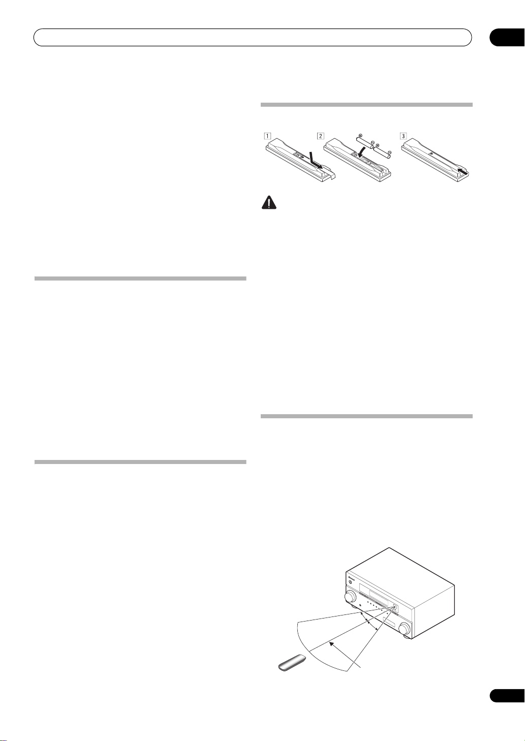
Loading the batteries
CAUTION
Incorrect use of batteries may result in such hazards as
leakage and bursting. Observe the following precautions:
•Never use new and old batteries together.
• Insert the plus and minus sides of the batteries
properly according to the marks in the battery case.
•Batteries with the same shape may have different
voltages. Do not use different batteries together.
•When disposing of used batteries, please comply
with governmental regulations or environmental
public instruction’s rules that apply in your country or
area.
• WARNING
Do not use or store batteries in dire
ct sunlight or
other e
xcessively hot place, such as inside a car or
near a heater. This can cause batteries to leak,
overheat, explode or catch fire. It can also reduce the
life or performance of batteries.
Operating range of remote control unit
The remote control may not work properly if:
•There are obstacles between the remote control and
the receiver’s remote sensor.
•Direct sunlight or fluorescent light is shining onto the
remote sensor.
•The receiver is located near a device that is emitting
infrared rays.
•The receiver is operated simultaneously with another
infrared remote control unit.
7 m (23 ft.)
30°
30°
Controls and displays
02
10
En
Chapter 2:
Controls and displays
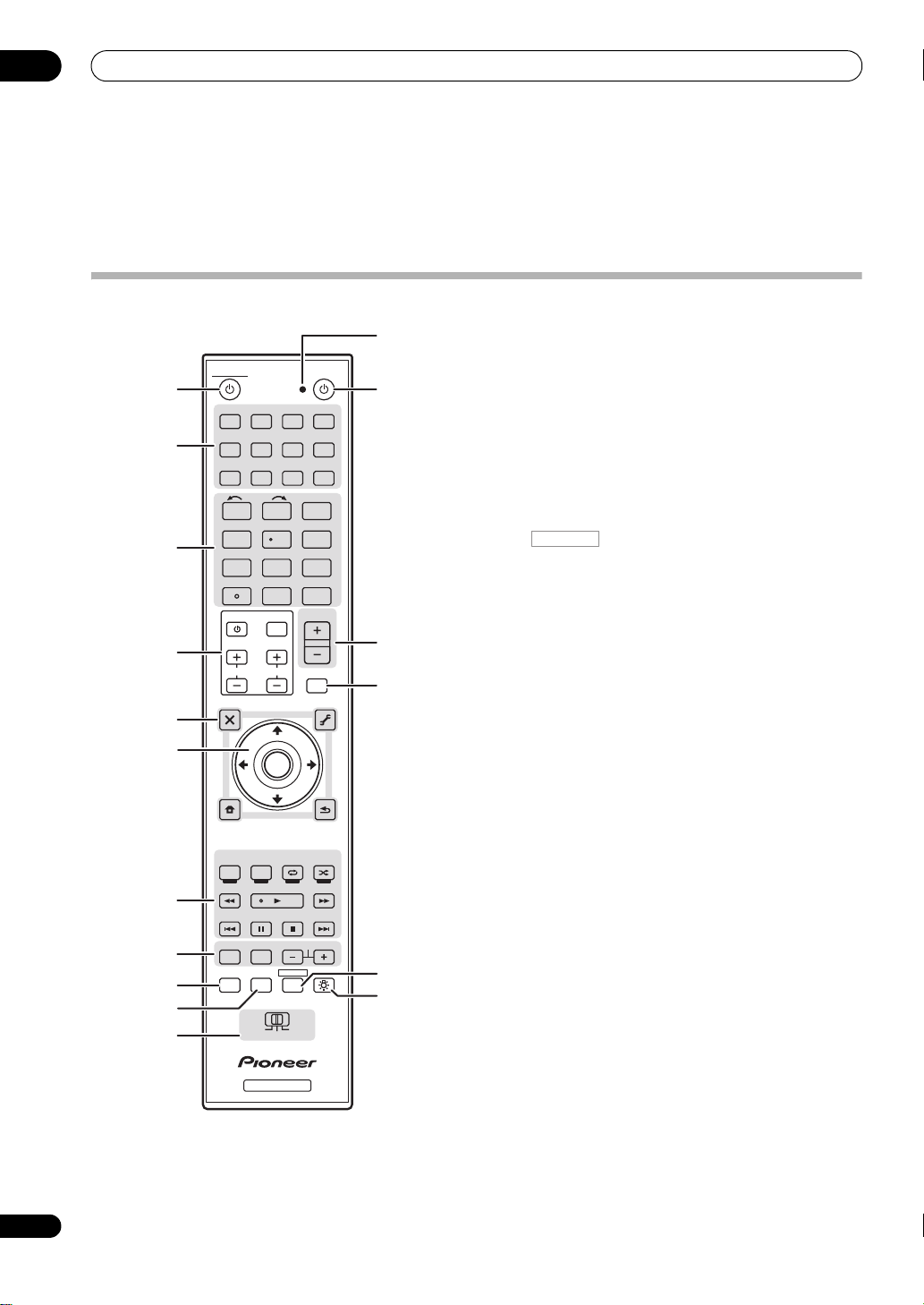
Remote control
The remote has been conveniently color-coded according
to component control using the following system:
• White – Receiver control, TV Control
• Blue – Other controls
1
RECEIVER
This switches between standby and on for this receiver.
2 Input function buttons
Press to select control of other components (see
Controlling the rest of your system on page 73).
3 Number buttons and other receiver/component
controls
Use the number buttons to directly select a radio
frequency (page 51) or the tracks on a CD, DVD, etc.
ENTER can be used to enter commands for TV or DTV.
Press first to access:
INPUT SELECT – Use to select the input function
(page 45).
VSX-23TXH only: HDMI OUT – Switch the HDMI
output terminal (page 71).
SIGNAL SEL – Use to select an input signal (page 61).
MCACC – Press to switch between MCACC presets
(page 61).
SLEEP – Use to put the receiver in sleep mode and
select the amount of time before sleep (page 71).
SBch
– Use to select the surround back/virtual surround
back channel mode
(page 59)
.
A.ATT – Attenuates (lowers) the level of an analog
input signal to prevent distortion (page 70).
DIMMER – Dims or brightens the display (page 71).
CH LEVEL – Press repeatedly to select a channel,
then use / to adjust the level (page 92).
Press TUNER first to access:
D.ACCESS – After pressing, you can access a radio
station directly using the number buttons (page 51).
CLASS – Switches between the seven banks (classes)
of radio station presets (page 51).
4
TV CONTROL
buttons
These buttons are dedicated to control the TV assigned to
TV operation selector switch. Thus if you only have one TV
to hook up to this system assign it to the TV operation
selector switch (see page 74 for more on this).
– Use to turn on/off the power of the TV.
INPUT – Use to select the TV input signal.
CH +/– – Use to select channels.
VOL +/– – Use to adjust the volume on your TV.
DVD BD DVR HDMI
TV CD CD-R
TUNER
INPUT
SELECT
VIDEO
iPod USB SIRIUSXM
INPUT
T.EDIT
GUIDE
TOP MENU
BAND
MUTE
RETURNCATEGORY
iPod CTRL
HOME
MENU
LIST
TOOLS
AUDIO
PARAMETER
VOL
AUTO/ALC/
DIRECT
PHASE CTRLTHX STATUS
REMOTE
SETUP
ZONE 2
MAIN
ZONE 3
HDD DVD
STANDARD
STEREO
MENU
ADV SURR
CH
TV CONTROL
123
SLEEP
HDMI OUT
MCACCSIGNAL SEL
456
DIMMERA.ATTSBch
789
CLASS
MASTER
VOLUME
CH LEVELD.ACCESS
0
ENTER
RECEIVER
SOURCE
ENTER
ANT
AUDIO
INFO
DISP
MPX PQLS
MEMORY
CH
RECEIVER
TUNE
PRESET PRESET
TUNE
VIDEO
PARAMETER
RECEIVER
TV CTRL
1
2
3
7
8
9
11
10
4
5
6
13
12
14
15
16
17
RECEIVER

Controls and displays
02
11
En
5 Tuner/component control buttons/
HOME MENU
These button controls can be accessed after you have
selected the corresponding input function button (DVD,
DVR, TV, etc.). The BAND and T.EDIT tuner controls are
explained on page 51.
Press first to access:
AUDIO PARAMETER – Use to access the Audio
options (page 66).
VIDEO PARAMETER – Use to access the Video
options (page 68).
HOME MENU – Use to access the Home Menu
(pages 40, 43, 64, 77, 90 and 94).
RETURN – Press to confirm and exit the current
menu screen (also use to return to the previous menu
with DVDs or to select closed captioning with DTV).
6
///
(
TUNE
/
PRESET
) /
ENTER
Use the arrow buttons when setting up your surround
sound system (see page 77) and the Audio or Video
options (page 66 or 68). Also used to control DVD menus/
options and for deck 1 of a double cassette deck player.
Use TUNE/ to find radio frequencies and use PRESET
/ to find preset stations (page 51).
7 Component/Receiver control buttons
The main buttons (, , etc.) are used to control a
component after you have selected it using the input
function buttons.
The controls above these buttons can be accessed after
you have selected the corresponding input function
button (for example DVD, DVR o r TV). These buttons also
function as described below.
Press TUNER first to access:
MPX
– Switches between stereo and mono reception
of FM broadcasts. If the signal is weak, then switching
to mono will improve the sound quality
(page 51)
.
Press first to access:
AUTO/ALC/DIRECT –
Switches between Auto
Surround
(page 56)
, Auto level control mode and
Stream Direct mode
(page 59).
STEREO – Switches between stereo playback and
Front Stage Surround Advance modes (page 58).
STANDARD – Press for Standard decoding and to
switch between the various 2 Pro Logic IIx and
Neo:6 options (page 56).
ADV SURR – Use to switch between the various
surround modes (page 58).
THX – Press to select a Home THX listening mode
(page 57).
PHASE CTRL – Press to switch on/off Phase Control
(page 61).
STATUS – Press to check selected receiver settings
(page 71).
PQLS – Press to select PQLS setting (page 65).
8
AUDIO – Changes the audio or channel on DVD or
BD discs.
DISP – Switches between named station presets and
radio frequencies.
CH +/– – Use to select channels for DVD/DVR units.
9
REMOTE SETUP
Use to input the preset code when making remote
control settings and to set the remote control mode
(page 73).
10
TV CTRL
Use this button to set preset code of your TV’s
manufacturer when controlling TV (see Selecting preset
codes directly on page 73 for more on this).
11
MULTI-ZONE
operation selector switch
Switch to perform operations in the main zone, ZONE 2
and ZONE 3 (VSX-23TXH only) (page 70).
12 Remote control LED
Lights when a command is sent from the remote control
(page 73).
13
SOURCE
Press to turn on/off other components connected to the
receiver (see page 73 for more on this).
14
MASTER VOLUME +/–
Use to set the listening volume.
15
MUTE
Mutes the sound or restores the sound if it has been
muted (adjusting the volume also restores the sound).
16
Switches the remote to control the receiver (used to
select the white commands above the number buttons
(A.ATT, etc.)). Also use this button to set up surround
sound.
17
Press to turn on/off the illumination of some of the
buttons.
RECEIVER
RECEIVER
RECEIVER
Controls and displays
02
12
En
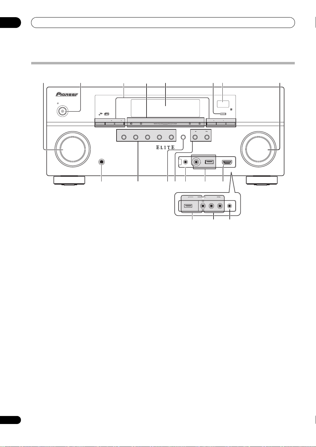
Front panel
1
INPUT SELECTOR
dial
Use to select an input function.
2
STANDBY/ON
Switches the receiver between on and standby. Power
indicator lights when the receiver is on.
When the KURO LINK function is set to ON, the power
indicator lights when the power is in standby.
3 Tuner controls
BAND – Switches between AM and FM radio bands
(page 51).
TUNE +/– – Use to find radio frequencies (page 51).
PRESET +/– – Use to find preset stations (page 51).
TUNER EDIT –
Use with
TUNE +/–
,
PRESET +/–
and
ENTER
to memorize and name stations for recall
(page 51)
.
4
PHASE CONTROL
indicator
–
Lights to indicate
Phase Control is selected
(page 61)
.
ADVANCED MCACC indicator
–
Lights when
EQ
is
set to
ON
in the
AUDIO PARAMETER
menu
(page 66)
.
VSX-23TXH only: PQLS indicator – Lights when the
PQLS feature is active (page 65).
HDMI
indicator
– Blinks when connecting an HDMI-
equipped component; lights when the component is
connected
(page 24)
.
5 Character display
See Display on page 13.
6
ENTER
7 Remote sensor
Receives the signals from the remote control (see
Operating range of remote control unit on page 9).
8
MASTER VOLUME
dial
9
PHONES
jack
Use to connect headphones. When the headphones are
connected, there is no sound output from the speakers.
10 Listening mode buttons
AUTO SURR/ALC/STREAM DIRECT –
Switches
between Auto Surround
(page 56)
, Auto level control
mode and Stream Direct mode
(page 59)
.
STEREO – Switches between stereo playback and
Front Stage Surround Advance modes (page 58).
ADVANCED SURROUND – Use to switch between
the various surround modes (page 58).
STANDARD SURROUND – Press for Standard
decoding and to switch between the various 2 Pro
Logic IIx and Neo:6 options (page 56).
HOME THX – Press to select a Home THX listening
mode (page 57).
11
SPEAKERS
Use to change the speaker system (page 69).
MASTER
VOLUME
INPUT
SELECTOR
STANDBY/ON
VSX-23TXH
PHONES
BAND TUNE TUNE
PHASE
CONTROL
AUTO SURR
/ALC/
STREAM DIRECT
ADVANCED
SURROUND
STANDARD
SURROUND
MCACC SETUP MIC
STEREO
SPEAKERSHOME THX
USB
CONTROL
MULTI-ZONE
ON
/
OFF
ADVANCED
MCACC
HDMIPQLS PRESET PRESET TUNER EDIT
ENTER
iPod
iPhone
VIDEO
CAMERA
HDMI 4
MCACC
SETUP
MIC
USB VIDEO L RAUDIO
iPod
iPhone
VIDEO 2
INPUT
12 345
910 141211 13
15
786
16 1314
VSX-23TXH
VSX-21TXH
Controls and displays
02
13
En
12
MULTI-ZONE
controls
If you’ve made MULTI-ZONE connections (see MULTI-
ZONE setup on page 33) use these controls to control the
sub zone from the main zone (see Using the MULTI-ZONE
controls on page 69).
13
MCACC SETUP MIC
jack
Use to connect the supplied microphone (page 41).
14
iPod/iPhone/USB
terminals
Use to connect your Apple iPod as an audio and video
source, or connect a USB device for audio and photo
playback (page 38).
15
VSX-23TXH only:
HDMI 4 input connector
Use for connection to compatible HDMI device (Video
camera, etc.). See Connecting an HDMI-equipped
component to the front panel input on page 37.
16
VSX-21TXH only: VIDEO 2 INPUT
terminals
Use to connect your portable equipment such as
camcorders, video games and portable audio/video
equipment. See Connecting a component to the front
panel inputs on page 38.
Display
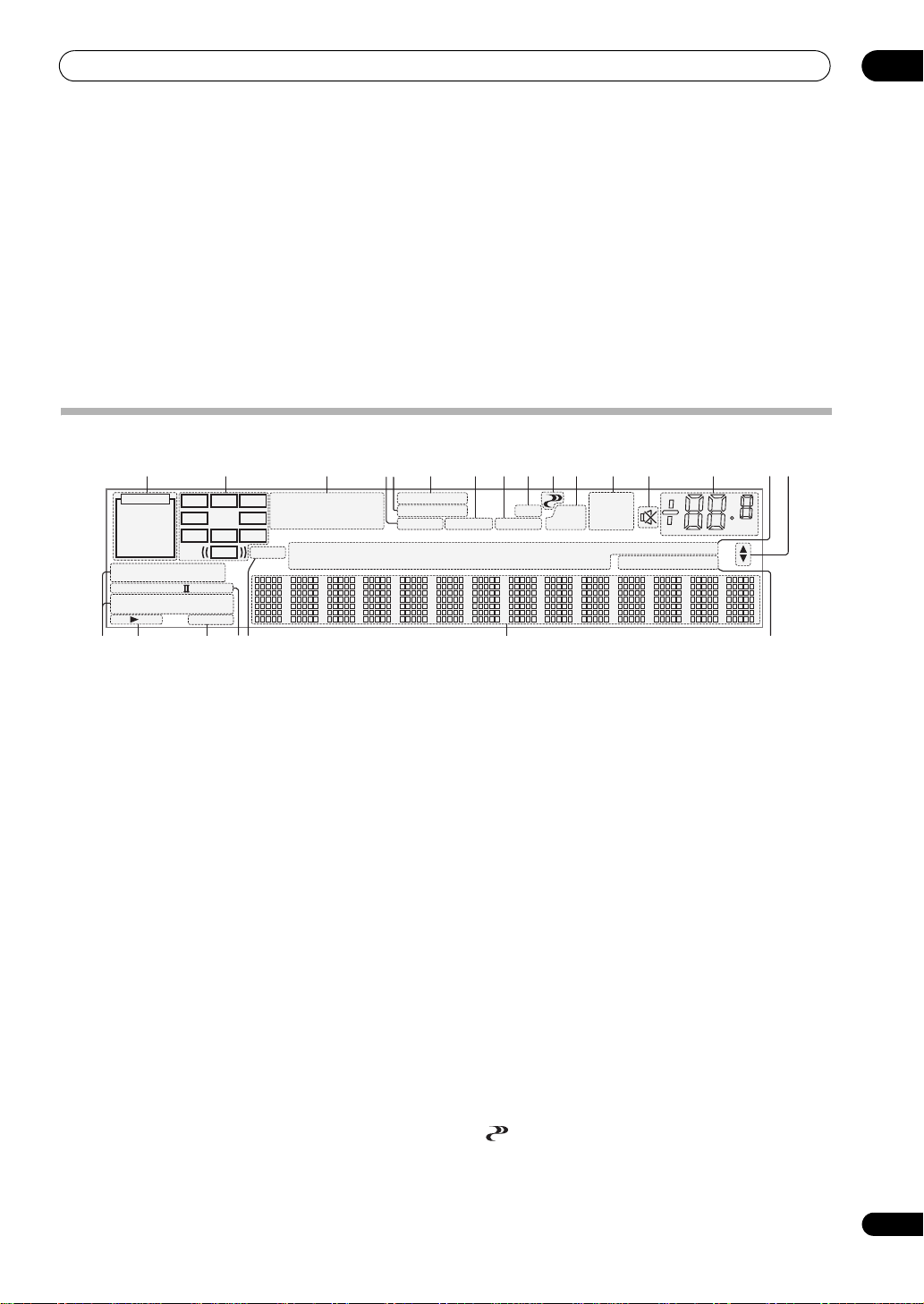
1
SIGNAL
indicators
Light to indicate the currently selected input signal.
AUTO lights when the receiver is set to select the input
signal automatically (page 61).
2 Program format indicators
Light to indicate the channels being input when PCM
signals are being input. They do not indicate the audio
signals being output from the receiver.
L/R – Left front/Right front channel
C – Center channel
SL/SR – Left surround/Right surround channel
LFE – Low frequency effects channel (the (( )) indicators light
when an LFE signal is being input)
XL/XR – Two channels other than the ones above
XC – Either one channel other than the ones above, the mono
surround channel or matrix encode flag
3 Digital format indicators
Light when a signal encoded in the corresponding format
is detected.
4
S.RTRV
Lights when the Sound Retriever function is
active
(page 66)
.
5
MULTI-ZONE
Lights when the MULTI-ZONE feature is active (page 69).
6
DSD PCM
–
Light during DSD (Direct Stream Digital) to
PCM conversion with SACDs.
PCM – Lights during playback of PCM signals.
7
SOUND
Lights when any of the Midnight, Loudness or tone
controls feature is selected (page 66).
Lights when Dialog Enhancement is switched on.
8
UP MIX
Lights when the Up Mix is switched on (page 60).
9 Listening mode indicators
AUTO SURROUND – Lights when the Auto Surround
feature is switched on (page 56).
ALC – Lights when the ALC (Auto level control) mode
is selected (page 59).
STREAM DIRECT – Lights when Direct/Pure Direct is
selected (page 59).
ADV.SURROUND – Lights when one of the
Advanced Surround modes has been selected
(page 58).
STEREO – Lights when stereo listening is switched
on (page 58).
STANDARD – Lights when one of the Standard
Surround modes is switched on (page 56).
THX – Lights when one of the Home THX modes is
selected (page 57).
10 (
PHASE CONTROL
)
Lights when the Phase Control is switched on (page 61).
PCM
HDMI
DIGITAL
ANALOG
LCR
SL SR
XL XR
XC
LFE
AUTO
DIGITAL PLUS
AUTO SURROUND
STREAM DIRECT
PROLOGIC
x
Neo:6
THX ADV.SURROUND
STEREO STANDARD
SP
AB
SLEEP
DSD PCM
DTS HD ES 96/24
MSTR
S.RTRV SOUND UP MIX
OVER
MONO
dB
2
MULTI-ZONE
STEREO
TrueHD WMA9Pro
TUNED
PQLS
ALC
AT T
2
2
USB XM
VIDEO
TV
DVD
HDMI
DVR
BD
CD
TUNER SIRIUS
CD-R
iPod
[ 2 ]
[ 3 ]
[ 4 ]
21 3 118 9765 1210 13 14 15
21 2217 18 19 20
16
9
4

Controls and displays
02
14
En
11 Analog signal indicators
Light to indicate reducing the level of an analog signal
(page 70).
12 Tuner indicators
TUNED – Lights when a broadcast is being received.
STEREO –
Lights when a stereo FM broadcast is being
received in auto stereo mode.
MONO – Lights when the mono mode is set using
MPX.
13
Lights when the sound is muted (page 11).
14 Master volume level
Shows the overall volume level.
“---” indicates the minimum level, and “+12dB” indicates
the maximum level.
15 Input function indicators
Light to indicate the input function you have selected.
16 Scroll indicators
Light when there are more selectable items when making
the various settings.
17 Speaker indicators
Lights to indicate the current speaker system, A and/or B
(page 69).
18
SLEEP
Lights when the receiver is in sleep mode (page 71).
19 Matrix decoding format indicators
2PRO LOGIC IIx – This lights to indicate 2 Pro
Logic II / 2 Pro Logic IIx decoding (page 56).
Neo:6 –
When one of the Neo:6 modes of the receiver
is on, this lights to indicate Neo:6 processing
(page 56)
.
20
MSTR
Lights during playback of DTS-HD Master Audio signal.
21 Character display
Displays various system information.
22 Remote control mode indicator
Lights to indicate the receiver’s remote control mode
setting. (Not displayed when set to 1.) (page 73)
Connecting your equipment
03
15
En
Chapter 3:
Connecting your equipment
This receiver provides you with many connection possibilities, but it doesn’t have to be difficult. This page explains the
kinds of components you can connect to make up your home theater system.
Important
•Illustration shows the VSX-23TXH, however connections for the VSX-21TXH are the same except where noted.
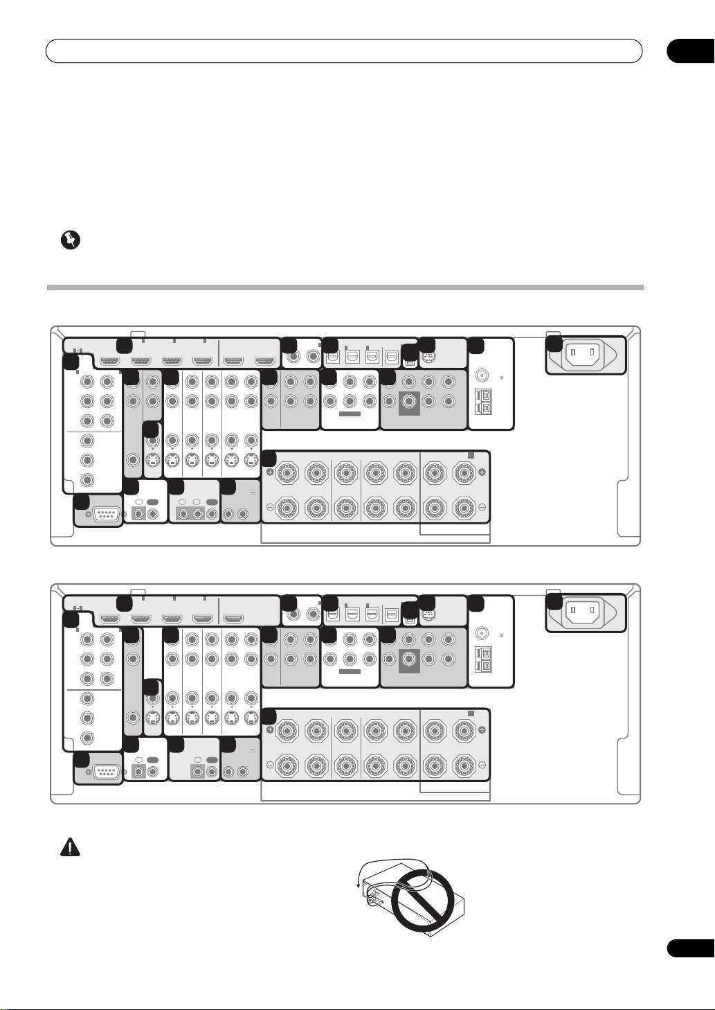
Rear panel
CAUTION
•Before making or changing the connections, switch
off the power and disconnect the power cord from the
power outlet. Plugging in should be the final step.
• To avoid hum, do not lay connected cables over the
top of the receiver.
RS-232C
COMPONENT
VIDEO
HDMI
ZONE2
VIDEO
S-VIDEO
ASSIGNABLE
ASSIGNABLE
ASSIGNABLE
ASSIGN-
ABLE
MONITOR
OUT
MONITOR
OUT
IN
Y
L
R
P
B
P
R
Y
P
B
P
R
Y
OUT
DVD
IN
TV/SAT
IN
VIDEO DVR
IN
CD
ININOUT
CD-R/TAPE
MULTI CH IN PRE OUT
ANTENNA
SIRIUS
XM
SPEAKERS
OPTICAL
AUDIO
FM UNMAL
75 ޓޓ
AM LOOP
AC IN
COAXIAL
INOUT
ZONE3
OUT
P
B
P
R
1
INBD IN
1
IN
2
IN OUT 1 OUT 2
(
KURO
LINK
)
(
DVD
)(
CD
)(
TV/SAT
)(
DVR
)(
VIDEO
)
(
Single
)
(
Single
)
3
IN
1
IN
1
A
B
IN
2
IN
OUT
IN
IN
FRONT
R
L RL
CENTER
SURROUND
R
L
SURROUND BACK /
FRONT CENTER SURROUND FRONT CENTER
L
R
SURROUND SURROUND
BACK
3
IN
2
1 3
(
DVD
)
IN
2
(
DVR
)
CONTROL IR
12 V TRIGGER
IN IN IN
OUT
OUT
12
12
(OUTPUT 12 V
TOT AL 50 mA MAX)
SUBWOOFER
SUBWOOFER
RS-232C
COMPONENT
VIDEO
HDMI
ZONE2
VIDEO
S-VIDEO
ASSIGNABLE
ASSIGNABLE
ASSIGNABLE
ASSIGN-
ABLE
MONITOR
OUT
MONITOR
OUT
IN
Y
L
R
P
B
P
R
Y
P
B
P
R
Y
OUT
DVD
IN
TV/SAT
IN
VIDEO DVR
IN
CD
ININOUT
CD-R/TAPE
MULTI CH IN PRE OUT
ANTENNA
SIRIUS
XM
SPEAKERS
OPTICAL
AUDIO
FM UNMAL
75 ޓޓ
AM LOOP
AC IN
COAXIAL
INOUT
P
B
P
R
1
INBD IN
1
IN
2
IN OUT
(
DVD
)(
CD
)(
TV/SAT
)(
DVR
)(
VIDEO
)
(
Single
)
(
Single
)
3
IN
1
IN
1
A
B
IN
2
IN
OUT
IN
IN
FRONT
R
L RL
CENTER
SURROUND
R
L
SURROUND BACK /
FRONT CENTER SURROUND FRONT CENTER
L
R
SURROUND SURROUND
BACK
3
IN
2
1 3
(
DVD
)
IN
2
(
DVR
)
CONTROL IR
12 V TRIGGER
IN IN
OUT
OUT
12
(OUTPUT 12 V
TOT AL 50 mA MAX)
SUBWOOFER
SUBWOOFER
7 9 10 11 12
13
19
2 3
4
5
1
6
8
16 17
18
14
15
7 9 10 11 12
13
19
2 3
4
5
1
6
8
16 17
18
14
15
VSX-23TXH
VSX-21TXH

Connecting your equipment
03
16
En
1 HDMI connectors (x6 (VSX-23TXH)/x5 (VSX-21TXH))
Multiple inputs and one (VSX-21TXH)/two (VSX-23TXH)
output(s) for high-quality audio/video connection to
compatible HDMI devices.
See Connecting your TV and playback components on
page 24.
VSX-23TXH only: See Switching the HDMI output on
page 71.
2 Coaxial digital audio inputs (x2)
Use for digital audio sources, including DVD players/
recorders, digital satellite receivers, CD players, etc.
See also The Input Setup menu on page 43 to assign
the inputs.
3 Optical digital audio output/input(s) (x4)
Use the OUT jack for recording to a CD or MiniDisc
recorder.
See Connecting other audio components on page 29.
Use the IN jacks for digital audio sources, including DVD
players/recorders, digital satellite receivers, CD players,
etc.
See also The Input Setup menu on page 43 to assign
the inputs.
4 XM Radio input
See Connecting an XM Radio tuner on page 32.
5 SIRIUS Radio input
See Connecting a SiriusConnect™ tuner on page 32.
6 Component video connectors (x3)
Use the inputs to connect any video source that has
component video output, such as a DVD player.
See Connecting your DVD player with no HDMI output
on page 25.
Use the output to connect monitor or TV.
See
Connecting your TV with no HDMI input on
page 26.
7 ZONE 2 and ZONE 3 (VSX-23TXH only) output(s)
Use to connect a second or third (VSX-23TXH only)
amplifier and monitors or TVs in a separate room.
See MULTI-ZONE setup on page 33.
8 Composite and S-Video monitor outputs
Use to connect monitors and TVs.
See
Connecting your TV with no HDMI input on
page 26.
9 Audio/video source inputs/(outputs) (x5)
Use for connection to audio/visual sources, such as DVD
players/recorders, VCRs, etc. Each set of inputs has jacks
for composite video, S-Video and stereo analog audio.
See Connecting an HDD/DVD recorder, VCR and other
video sources on page 28.
10 Stereo analog audio source inputs/(outputs) (x3)
Use for connection to audio sources such as CD players,
tape decks, turntables, etc.
See Connecting other audio components on page 29.
11 Multichannel analog audio inputs
7.1 channel inputs for connection to a DVD player with
multichannel analog outputs.
See Connecting the multichannel analog inputs on
page 29.
12 Multichannel pre-amplifier outputs
Use to connect separate amplifiers for front, center,
surround, surround back and subwoofer channels.
See Connecting additional amplifiers on page 30 (see
also Installing your speaker system on page 20 for
powered subwoofer connection).
13 AM and FM antenna terminals
Use to connect indoor or outdoor antennas for radio
broadcasts.
See Connecting AM/FM antennas on page 31.
14 RS-232C connector
Use for connection to a PC for graphical output when
using Advanced MCACC.
See Connecting a PC for Advanced MCACC output on
page 36.
15 Control input/output
Use to connect other Pioneer components so that you
can control all your equipment from a single IR remote
sensor.
See Operating other Pioneer components with this
unit’s sensor on page 35.
16 Remote input(s)/output (x3 (VSX-23TXH)/x2 (VSX-
21TXH))
Use for connection to an external remote control sensor
for use in a MULTI-ZONE setup, for example.
See Connecting an IR receiver on page 35.
17 12 V trigger jacks
(total 50 mA max.)
(x2)
Use to switch components in your system on and off
according to the input function of the receiver.
See Switching components on and off using the 12
volt trigger on page 36.
18 Speaker terminals
Use for connection to the main front, center, surround
and surround back speakers.
See Connecting the speakers on page 19.
19 AC power inlet
Connect the supplied power cord here.
See Plugging in the receiver on page 39.
Connecting your equipment
03
17
En
Determining the speakers’ application
Surround sound with a strong sense of presence can be
enjoyed by connecting 7 speakers and 1 subwoofer. It is
also possible to achieve high sound quality using bi-amp
connections and to enjoy music in other rooms using the
MULTI-ZONE feature. High sound quality can be
achieved with a minimum of two speakers.
•Be sure to connect speakers to the front left and right
channels ( and ).
•The Surr Back System setting must be made if you
use any of the connections shown below other than
[1] (see Selecting the Surr Back system on page 22).
[1] 7.1ch surround connection
(Simple connection & Best surround)
*Default setting
These connections prioritize surround sound with a
speaker layout like that in a movie theater.
• Surr Back System setting: Normal (default)
• If you have six speakers, either only connect one
surround back speaker (6.1 ch surround), or connect
for the 7.1-channel setting as shown on the diagram
below but without the center speaker.
[2] 5.1ch surround & Front Bi-amping connection
(High quality surround)
Bi-amping connection of the front speakers for high
sound quality with 5.1-channel surround sound.
• Surr Back System setting: Front Bi-Amp
*Bi-amp compatible speaker
[3] 5.1ch surround & ZONE 2 connection
(Multi Zone)
With these connections you can simultaneously enjoy
5.1-channel surround sound in the main zone with stereo
playback on another component in ZONE 2. (The
selection of input devices is limited.)
• Surr Back System setting: ZONE 2
[4]
5.1ch surround & Speaker B connection
With these connections you can simultaneously enjoy
5.1-channel surround sound in the main zone with stereo
playback of the same sound on the B speakers.
• Surr Back System setting: Speaker B
Other speaker connection
•Your favorite speaker connections can be selected
even if you have fewer than 5.1 speakers.
• When not connecting a subwoofer, connect speakers
with low frequency reproduction capabilities to the
front channel. (The subwoofer’s low frequency
component is played from the front speakers, so the
speakers could be damaged.)
•
After connecting, be sure to conduct the Auto
MCACC (speaker environment setting) procedure.
See Automatically setting up for surround sound
(Auto MCACC) on page 41.
L
R
SW
C
LR
SL
SBL SBR
SR
Subwoofer
Center
Front
right
Front
left
Surround
left
Surround
right
Surround
back left
Surround
back right
SW
C
LR
SL
SR
Subwoofer
Center
Front
right*
Front
left*
Surround
left
Surround
right
SW
C
LR
SL
SR
L
ZONE 2
R
Subwoofer
Center
Front
right
Front
left
Right
Left
Surround
left
Surround
right
SW
C
LR
SL
SR
Subwoofer
Center
Front
right
Front
left
Speaker B
Surround
left
Surround
right
Connecting your equipment
03
18
En
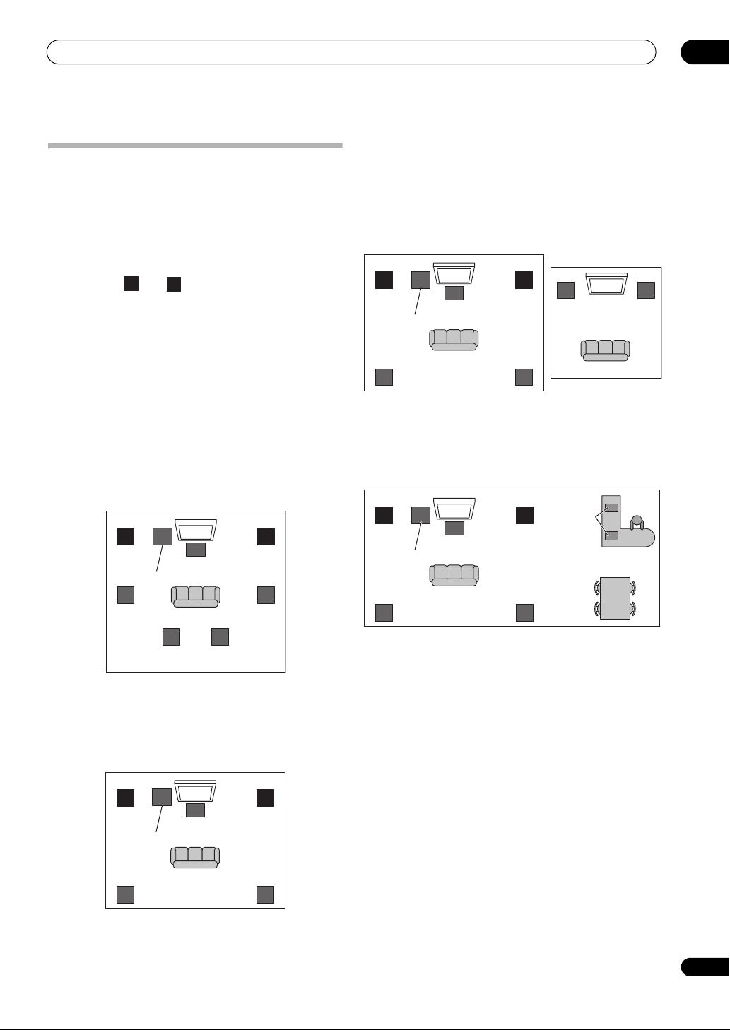
Placing the speakers
To achieve the best possible surround sound, install your
speakers as shown below.
5.1 channel surround system:
6.1 channel surround system:
7.1 channel surround system:
THX speaker system setup
If you are using a THX certified subwoofer use the THX
INPUT jack on the subwoofer (if your subwoofer has one)
or switch the filter position to THX on your subwoofer.
See also THX Audio Setting on page 93 to make the
settings that will give you the best sound experience
when using the Home THX modes (page 57).
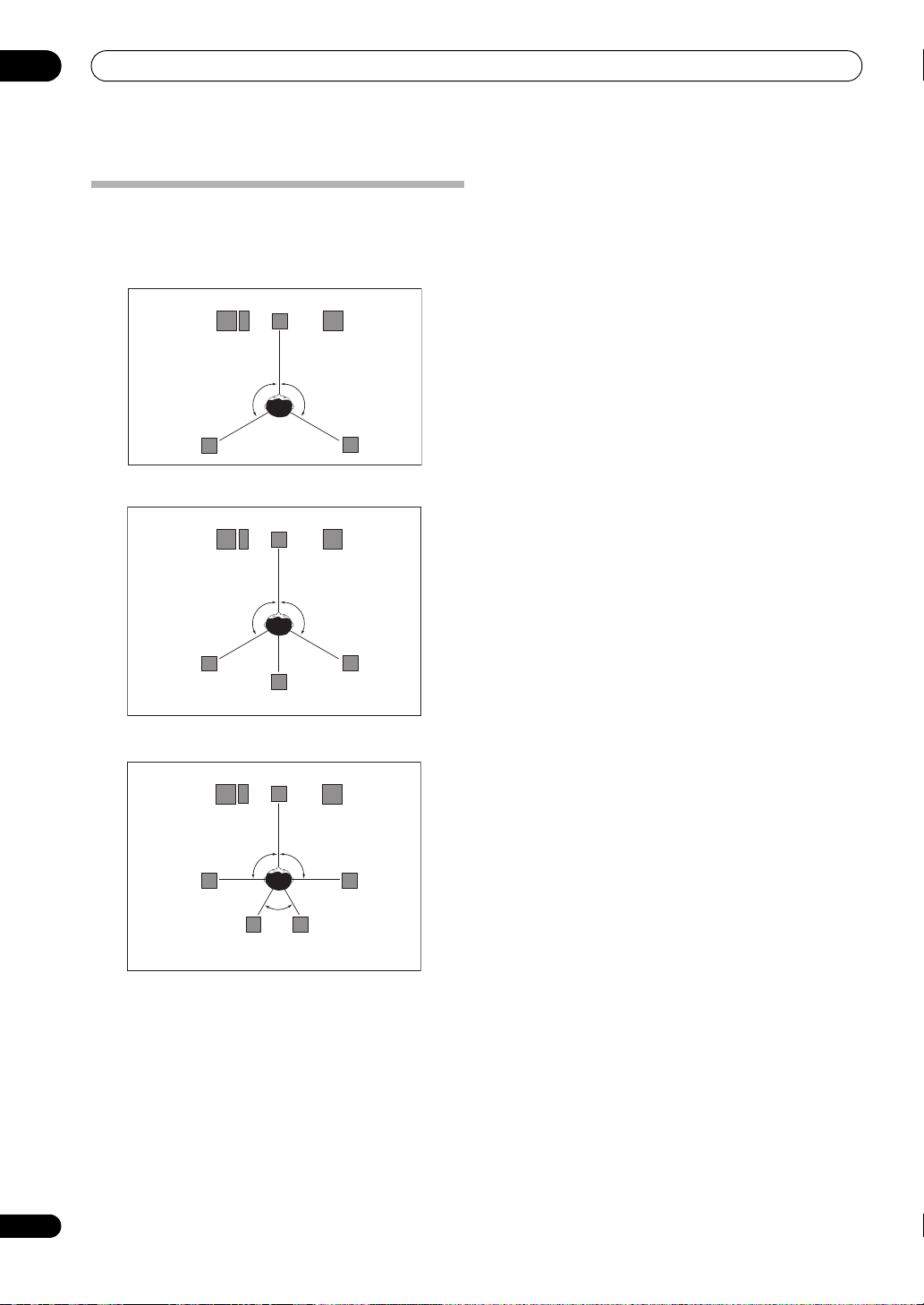
Some tips for improving sound quality
Where you put your speakers in the room has a big effect
on the quality of the sound. The following guidelines
should help you to get the best sound from your system.
•The subwoofer can be placed on the floor. Ideally, the
other speakers should be at about ear-level when
you’re listening to them. Putting the speakers on the
floor (except the subwoofer), or mounting them very
high on a wall is not recommended.
•For the best stereo effect, place the front speakers 2
m to 3 m (6 ft. to 9 ft.) apart, at equal distance from
the TV.
•If you’re using a center speaker, place the front
speakers at a wider angle. If not, place them at a
narrower an
gl
e.
• Place the center speaker above or below the TV so
that the sound of the center channel is localized at
the TV screen. Also, make sure the center speaker
does not cross the line formed by the leading edge of
the front left and right speakers.
• It is best to angle the speakers towards the listening
position. The angle depends on the size of the room.
Use less of an angle for bigger rooms.
•Surround and surround back speakers should be
positioned 60 cm to 90 cm (2 ft. to 3 ft.) higher than
your ears and tilted slight downward. Make sure the
speakers don’t face each other. For DVD-Audio, the
speakers should be more directly behind
the listen
er
than for home theater playback.
•If the surround speakers cannot be set directly to the
side of the listening position with a 7.1-channel
system, the surround effect can be enhanced by
turning off the Up Mix function (see Setting the Up
Mix function on page 60).
•Try not to place the surround speakers farther away
from the listening position than the front and center
speakers. Doing so can weaken the surround sound
effect.
Center
Front left
Front right
Surround
left
Surround
right
Subwoofer
120°
120°
Center
Front left
Front right
Surround
left
Surround
right
Subwoofer
120°
120°
Surround Back
Center
Front left
Front right
Surround
left
Surround
right
Subwoofer
90°
90°
Surround back
left
Surround back
right
60°
Connecting your equipment
03
19
En
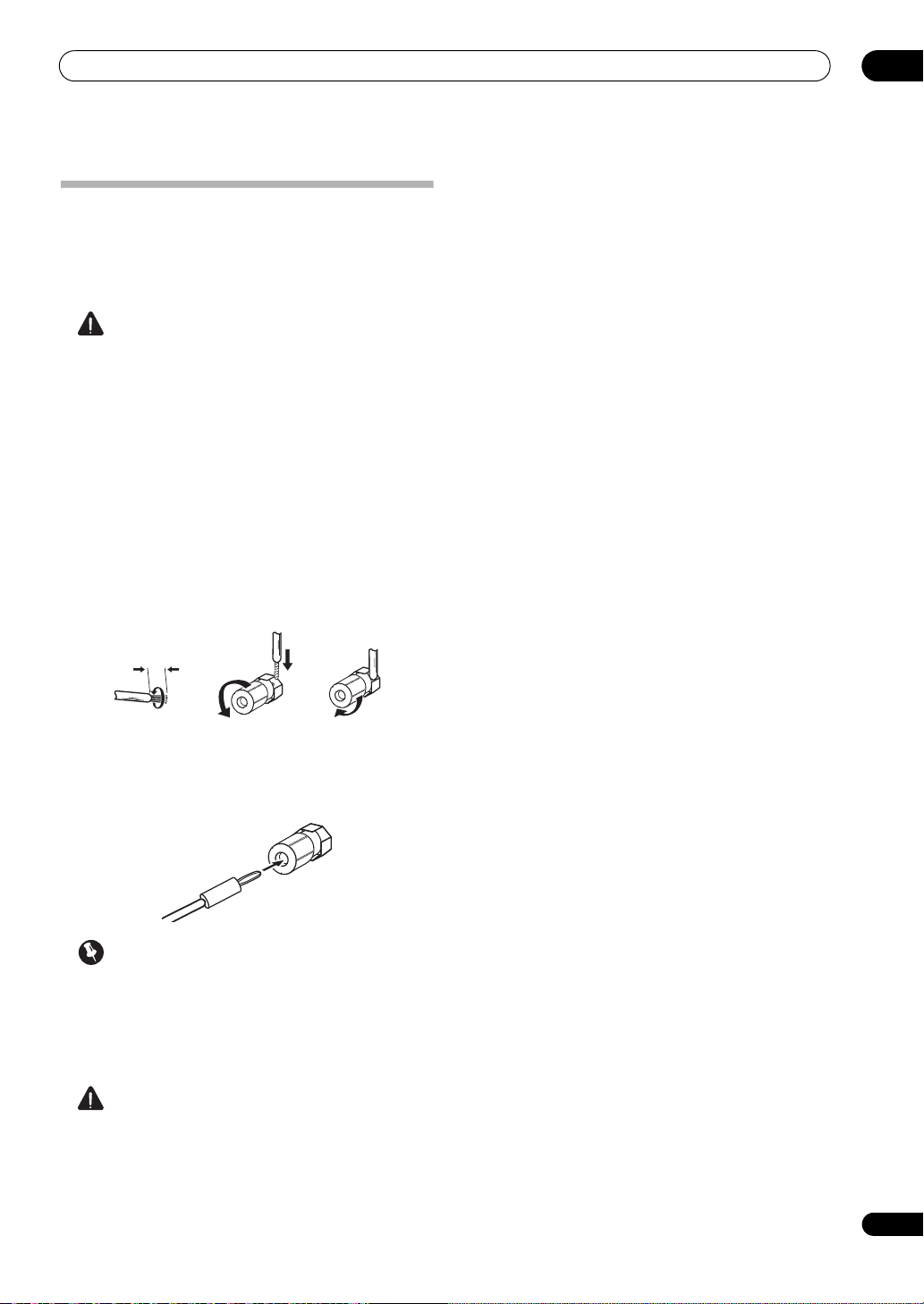
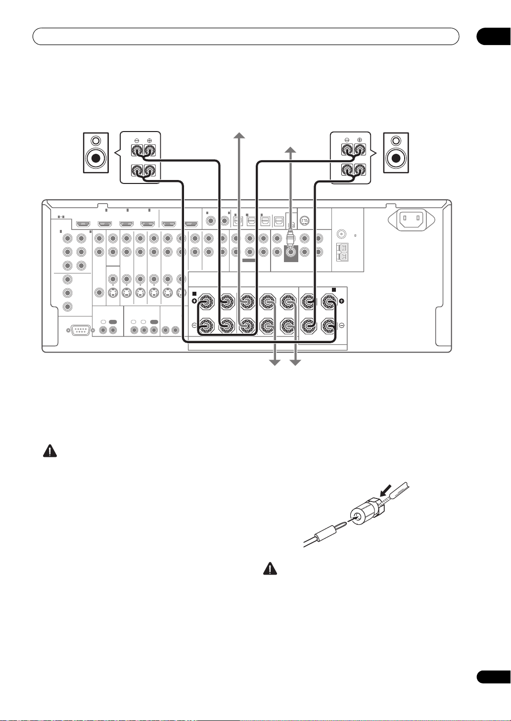
Connecting the speakers
Each speaker connection on the receiver comprises a
positive (+) and negative (–) terminal. Make sure to
match these up with the terminals on the speakers
themselves.
CAUTION
•These speaker terminals carry HAZARDOUS LIVE
voltage. To prevent the risk of electric shock when
connecting or disconnecting the speaker cables,
disconnect the power cord before touching any
uninsulated parts.
•Make sure that all the bare speaker wire is twisted
together and inserted fully into the speaker terminal.
If any of the bare speaker wire touches the back panel
it may cause the power to c
ut off as a safety measure.
Bare wire connections
1 Twist exposed wire strands together.
(fig. A)
2 Loosen terminal and insert exposed wire.
(fig. B)
3 Tighten terminal.
(fig. C)
Banana plug connections
If you want to use speaker cables terminated with banana
plugs, screw the speaker terminal fully shut, then plug
the banana plug into the end of the speaker terminal.
Important
•Please refer to the manual that came with your
speakers for details on how to connect the other end
of the speaker cables to your speakers.
• Use an RCA cable to connect the subwoofer. It is not
possible to connect using speaker cables.
CAUTION
•Make sure that all speakers are securely installed.
This not only improves sound quality, but also
reduces the risk of damage or injury resulting from
speakers being knocked over or falling in the event of
extern
al shocks such as earth
quakes.
fig. A fig. B fig. C
10 mm (
3
/
8
in.)
Connecting your equipment
03
20
En
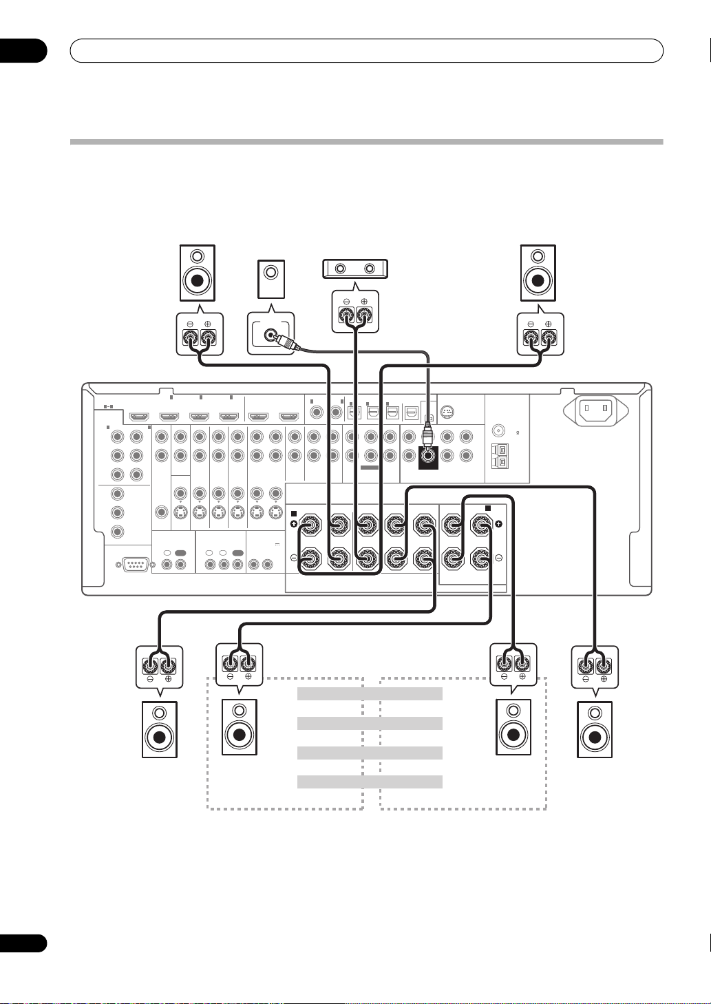
Installing your speaker system
At the very least, front left and right speakers only are necessary. Note that your main surround speakers should always
be connected as a pair, but you can connect just one surround back speaker if you like (it must be connected to the
left surround back terminal).
Standard 5.1/6.1/7.1-channel surround connections
RS-232C
COMPONENT
VIDEO
HDMI
ZONE2
VIDEO
S-VIDEO
ASSIGNABLE
ASSIGNABLE
ASSIGNABLE
ASSIGN-
ABLE
MONITOR
OUT
MONITOR
OUT
IN
Y
L
R
P
B
P
R
Y
P
B
P
R
Y
OUT
DVD
IN
TV/SAT
IN
VIDEO DVR
IN
CD
ININOUT
CD-R/TAPE
MULTI CH IN PRE OUT
ANTENNA
SIRIUS
XM
SPEAKERS
OPTICAL
AUDIO
FM UNMAL
75 ޓޓ
AM LOOP
AC IN
COAXIAL
INOUT
ZONE3
OUT
P
B
P
R
1
INBD IN
1
IN
2
IN OUT 1 OUT 2
(
KURO
LINK
)
(
DVD
)(
CD
)(
TV/SAT
)(
DVR
)(
VIDEO
)
(
Single
)
(
Single
)
3
IN
1
IN
1
A
B
IN
2
IN
OUT
IN
IN
FRONT
R
L RL
CENTER
SURROUND
R
L
SURROUND BACK /
FRONT CENTER SURROUND FRONT CENTER
L
R
SURROUND SURROUND
BACK
3
IN
2
1 3
(
DVD
)
IN
2
(
DVR
)
CONTROL IR
12 V TRIGGER
IN IN IN
OUT OUT
12
12
(OUTPUT 12 V
TOTAL 50 mA MAX)
SUBWOOFER
SUBWOOFER
LINE LEVEL
INPUT
Front left
Subwoofer
Center
Surround right
Surround back right
Surround back left
Front right
Surround left
The surround back terminals can also be
used for the Speaker B and ZONE 2.
7.1 ch surround setting
No connectSurround back
Speaker B setting
Speaker B - Left
Speaker B - Right
ZONE 2 setting
ZONE 2 - Left
ZONE 2 - Right
6.1 ch surround setting
VSX-23TXH
Connecting your equipment
03
21
En
Bi-amping your speakers
Bi-amping is when you connect the high frequency driver
and low frequency driver of your speakers to different
amplifiers for better crossover performance. Your
speakers must be bi-ampable to do this (having separate
terminals for high and low) and the sound improvement
will depend on the kind of speakers you’re using.
CAUTION
•Most speakers with both High and Low terminals
have two metal plates that connect the High to the
Low terminals. These must be removed when you are
bi-amping the speakers or yo
u c
ould severely
damage the amplifier. See your speaker manual for
more information.
•If your speakers have a removable crossover network,
make sure you do not remove it for bi-amping. Doing
so may damage your speakers.
Bi-wiring your speakers
Your speakers can also be bi-wired if they support bi-
amping.
• With these connections, the Surr Back System
setting makes no difference.
• To bi-wire a speaker, connect two speaker cords to
the speaker terminal on the receiver.
Using a banana plug for the second connection is
recommended.
CAUTION
• Don’t connect different speakers from the same
terminal in this way.
•When bi-wiring as well, heed the cautions for bi-
amping shown at the left.
RS-232C
COMPONENT
VIDEO
HDMI
ZONE2
VIDEO
S-VIDEO
ASSIGNABLE
ASSIGNABLE
ASSIGNABLE
ASSIGN-
ABLE
MONITOR
OUT
MONITOR
OUT
IN
Y
L
R
P
B
P
R
Y
P
B
P
R
Y
OUT
DVD
IN
TV/SAT
IN
VIDEO DVR
IN
CD
ININOUT
CD-R/TAPE
MULTI CH IN
PRE OU
T
PRE OUT
ANTENNA
SIRIUS
XM
SPEAKERS
OPTICAL
AUDIO
FM UNMAL
75 ޓޓ
AM LOOP
AC IN
COAXIAL
INOUT
ZONE3
OUT
P
B
P
R
1
INBD IN
1
IN
2
IN OUT 1 OUT 2
(
KURO
LINK
)
(
DVD
)(
CD
)(
TV/SAT
)(
DVR
)(
VIDEO
)
(
Single
)
(
Single
)
3
IN
1
IN
1
A
B
IN
2
IN
OUT
IN
IN
FRONT
R
L RL
CENTER
SURROUND
R
L
SURROUND BACK /
FRONT CENTER SURROUND FRONT CENTER
L
R
SURROUND SURROUND
BACK
3
IN
2
1 3
(
DVD
)
IN
2
(
DVR
)
CONTROL IR
12 V TRIGGER
IN IN IN
OUT OUT
12
12
(OUTPUT 12 V
TOTAL 50 mA MAX)
SUBWOOFER
SUBWOOFER
High
Low
High
Low
Front left
Subwoofer
Center
Surround right
Front right
Surround left
Bi-amp compatible
speaker
Bi-amp compatible
speaker
VSX-23TXH
Connecting your equipment
03
22
En
Selecting the Surr Back system
The surround back terminals can be used for bi-amping,
Speaker B a nd ZONE 2 conne ctions, in a ddition to for the
surround back speakers. Make this setting according to
the application.
ZONE 2 setup
With these connections you can simultaneously enjoy
5.1-channel surround sound in the main zone with stereo
playback on another component in ZONE 2.
1 Connect a pair of speakers to the surround back
speaker terminals.
See Standard 5.1/6.1/7.1-channel surround connections
on page 20.
2 Select ‘
ZONE 2
’ from the
Surr Back System
menu.
See Surround back speaker setting on page 91 to do this.
Speaker B setup
You can listen to stereo playback in another room.
1 Connect a pair of speakers to the surround back
speaker terminals.
See Standard 5.1/6.1/7.1-channel surround connections
on page 20.
2 Select ‘
Speaker B
’ from the
Surr Back System
menu.
See Surround back speaker setting on page 91 to do this.
Bi-Amping setup
Bi-amping connection of the front speakers for high
sound quality with 5.1-channel surround sound.
1 Connect Bi-amp compatible speakers to the front
and surround back speaker terminals.
See Bi-amping your speakers on page 21.
2 Select ‘
Front Bi-Amp
’ from the
Surr Back System
menu.
See Surround back speaker setting on page 91 to do this.
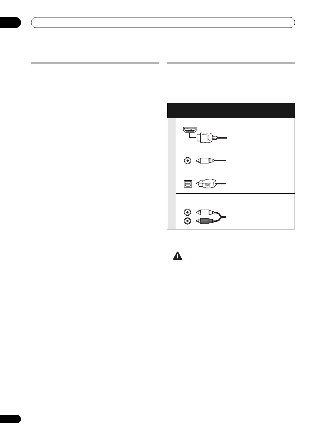
About the
audio connection
There are several types of audio input and output
terminals on this receiver. The receiver selects the first
available signal in the following order when you choose
AUTO as the input signal:
• With an HDMI cable, video and audio signals can be
transferred in high quality over a single cable.
CAUTION
• When connecting optical cables, be careful when
inserting the plug not to damage the shutter
protecting the optical socket.
• When storing optical cable, coil loosely. The cable
may be damaged if bent around sharp corners.
Types of cables and
terminals
Transferable audio
signals
Sound signal priority
HDMI HD audio
Digital (Coaxial) Conventional digital audio
Digital (Optical)
RCA (Analog)
(White/Red)
Conventional analog audio
Connecting your equipment
03
23
En
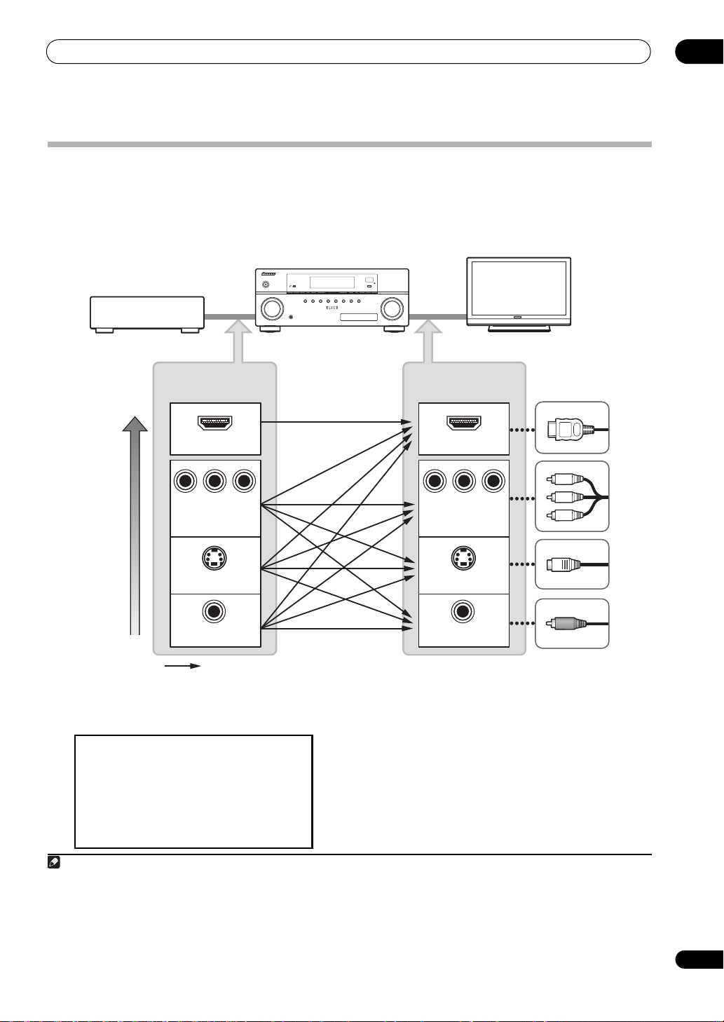
About the video converter
The video converter ensures that all video sources are output through all of the MONITOR OUT jacks. The only
exception is HDMI: since this resolution cannot be downsampled, you must connect your monitor/TV to the receiver’s
HDMI video outputs when connecting this video source.
1
If several video components are assigned to the same input function (see The Input Setup menu on page 43), the
converter gives priority to HDMI, component, S-Video, then composite (in that order).
•For optimal video performance, THX recommends
switching Digital Video Conversion (in Setting the
Video options on page 68) OFF.
Note
1 • If the video signal does not appear on your TV or flat panel TV, try adjusting the resolution settings on your component or display. Note that
some components (such as video game units) have resolutions that may not be converted. In this case, try switching Digital Video Conversion
(in Setting the Video options on page 68) OFF.
• The signal input resolutions that can be converted from the component video input for the HDMI output are 480i/576i, 480p/576p, 720p and
1080i. 1080p signal cannot be converted.
• Only signals with an input resolution of 480i/576i can be converted from the component video input for the composite and S-Video MONITOR
OUT.
HDMI IN
VIDEO IN
VIDEO
MONITOR OUT
COMPONENT
VIDEO IN
S-VIDEO IN S-VIDEO
MONITOR OUT
HDMI OUT
Y
P
B
P
R
Y
P
B
P
R
COMPONENT VIDEO
MONITOR OUT
High picture quality
Terminal for
connection with
source device
Terminal for
connection with TV
monitor
Video signals can be output
This receiver
Source device
TV monitor
Types of cables
This product incorporates copyright protection
technology that is protected by method claims of certain
U.S. patents and other intellectual property rights owned
by Macrovision Corporation and other rights owners.
Use of this copyright protection technology must be
authorized by Macrovision Corporation, and is intended
for home and other limited viewing uses only unless
otherwise authorized by Macrovision Corporation.
Reverse engineering or disassembly is prohibited.
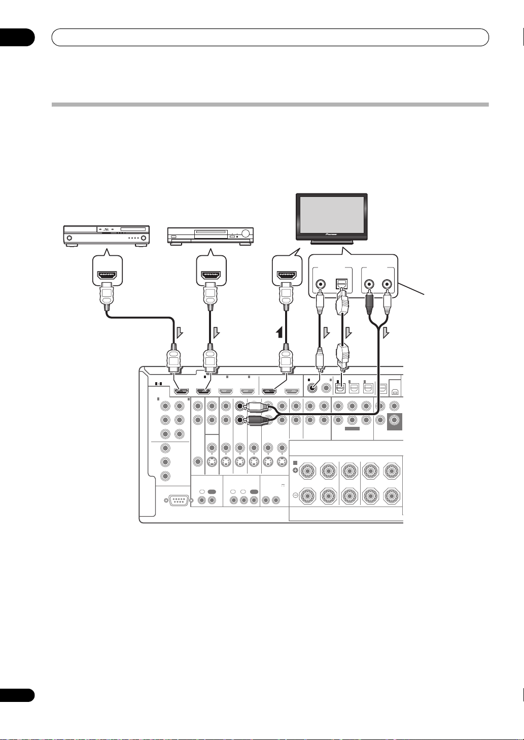
Connecting your equipment
03
24
En
Connecting your TV and playback components
Connecting using HDMI
If you have an HDMI or DVI (with HDCP) equipped component (Blu-ray disc player, etc.), you can connect it to this
receiver using a commercially available HDMI cable.
If the TV and playback components support the Pioneer KURO LINK feature, the convenient KURO LINK functions can
be used (see KURO LINK on page 63).
• When connecting a Blu-ray disc player, connect the
player to the receiver’s BD IN terminal.
• VSX-23TXH only: When connecting to an HDMI/DVI-
compatible monitor o r a flat panel TV using the HDMI
OUT 2 terminal, switch the HDMI output setting to
HDMI OUT 2 or HDMI OUT ALL. See Switching the
HDMI output on page 71.
•The HDMI indicator lights on the front panel when an
HDMI-equipped component is connected.
•For input co
mpon
ents, connections other than HDMI
connections are also possible (see Connecting your
DVD player with no HDMI output on page 25).
•If your Blu-ray disc player offers multi-channel analog
audio outputs, see Connecting the multichannel
analog inputs on page 29.
• The sound of the TV cannot be heard over the receiver
if the TV is connected using an HDMI cable.
If you want to listen to the sound of the TV over the
receiver, connect the receiver and TV with audio
cables. When making digital connections with a
coaxial cable at this time, the digital input setting
must be made (see The Input Setup menu on
page 43).
RS-232C
COMPONENT
VIDEO
HDMI
ZONE2
VIDEO
S-VIDEO
ASSIGNABLE
ASSIGNABLE
ASSIGNABLE
ASSIGN-
ABLE
MONITOR
OUT
MONITOR
OUT
IN
Y
L
R
P
B
P
R
Y
P
B
P
R
Y
OUT
DVD
IN
TV/SAT
IN
VIDEO DVR
IN
CD
ININOUT
CD-R/TAPE
MULTI CH IN PRE
XM
SPEAKERS
OPTICAL
COAXIAL
INOUT
ZONE3
OUT
P
B
P
R
1
INBD IN
1
IN
2
IN OUT 1 OUT 2
(
KURO
LINK
)
(
DVD
) (
CD
) (
TV/SAT
) (
DVR
)(
VIDEO
)
3
IN
1
IN
1
A
IN
2
IN
OUT
IN
FRONT
R
L RL
CENTER
SURROUND
FRONT CENTER SURROUND FRONT CENTER
S
3
IN
2
1 3
(
DVD
)
IN
2
(
DVR
)
CONTROL IR
12 V TRIGGER
IN IN IN
OUT OUT
12
12
(OUTPUT 12 V
TOTAL 50 mA MAX)
SUBWOOFER
SUBWOOFER
DIGITAL OUT
COAXIAL OPTICAL
ANALOG
RL
AUDIO OUT
HDMI INHDMI OUTHDMI OUT
Other HDMI/DVI-
equipped component
HDMI/DVI-compatible
Blu-ray disc player
HDMI/DVI-compatible monitor
or flat panel TV
Select one
This connection is
required in order to
listen to the sound of
the TV over the receiver.
VSX-23TXH
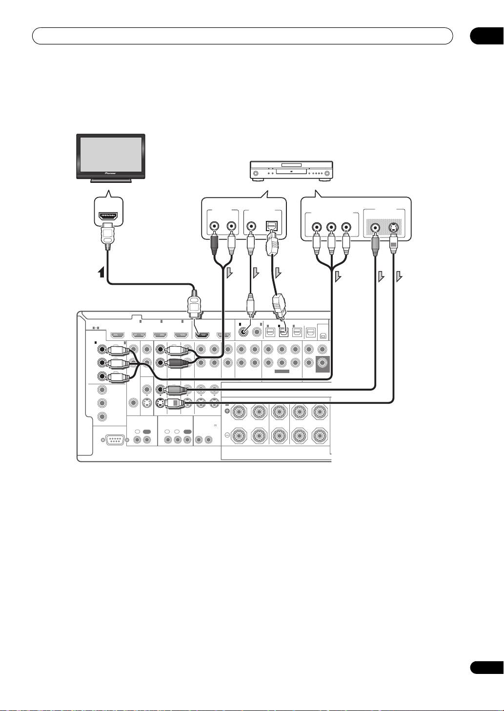
Connecting your equipment
03
25
En
Connecting your DVD player with no HDMI output
This diagram shows connections of a TV (with HDMI input) and DVD player (or other playback component with no
HDMI output) to the receiver.
• If you want to listen to the sound of the TV over the
receiver, connect the receiver and TV with audio
cables.
•Component video should give superior picture quality
when compared to composite
or S-Video. You can also
take advantage of progressive scan video (if your
source and TV are both compatible), which delivers a
very stable, flicker-free picture. See the manuals that
came with your TV and source component to check
whether they are compatible with progressive-scan
video.
•If your DVD player offers multi-channel analog audio
outputs, see Connecting the multichannel analog inputs
on page 29
.
RS-232C
COMPONENT
VIDEO
HDMI
ZONE2
VIDEO
S-VIDEO
ASSIGNABLE
ASSIGNABLE
ASSIGNABLE
ASSIGN-
ABLE
MONITOR
OUT
MONITOR
OUT
IN
Y
L
R
P
B
P
R
Y
P
B
P
R
Y
OUT
DVD
IN
TV/SAT
IN
VIDEO DVR
IN
CD
ININOUT
CD-R/TAPE
MULTI CH IN PRE
XM
SPEAKERS
OPTICAL
COAXIAL
INOUT
ZONE3
OUT
P
B
P
R
1
INBD IN
1
IN
2
IN OUT 1 OUT 2
(
KURO
LINK
)
(
DVD
) (
CD
)(
TV/SAT
) (
DVR
) (
VIDEO
)
3
IN
1
IN
1
A
IN
2
IN
OUT
IN
FRONT
R
L RL
CENTER
SURROUND
FRONT CENTER SURROUND FRONT CENTER
S
3
IN
2
1 3
(
DVD
)
IN
2
(
DVR
)
CONTROL IR
12 V TRIGGER
IN IN IN
OUT OUT
12
12
(OUTPUT 12 V
TOTAL 50 mA MAX)
SUBWOOFER
SUBWOOFER
HDMI IN
ANALOG
R
AUDIO OUT
VIDEO OUT
VIDEO S-VIDEO
Y
P
B
PR
COMPONENT VIDEO OUT
DIGITAL OUT
COAXIAL OPTICAL
L
DVD player, etc.
HDMI/DVI-compatible
monitor or flat panel TV
Select one
Select one
VSX-23TXH
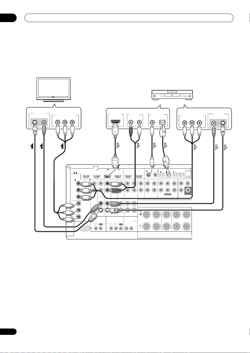
Connecting your equipment
03
26
En
Connecting your TV with no HDMI input
This diagram shows connections of a TV (with no HDMI input) and DVD player (or other playback component) to the
receiver.
• With these connections, the picture is not output to the TV even if the DVD player i s co nne cte d with an HDMI cab le.
Connect the DVD player’s video signals using a composite,
S-Video or component cord.
• Connect using an HDMI cable to listen to HD audio
on the receiver. Do not use an HDMI cable to input
video signals.
Depending on the video component, it may not be
possible to output signals connected by HDMI and
other methods simultaneously, and it may be
necessary to make output settings.
Please refer to the
operating instructions
supplied with your component
for more information.
•Component video should give superior picture quality
when compared to composite
or S-Video. You can also
take advantage of progressive scan video (if your
source and TV are both compatible), which delivers a
very stable, flicker-free picture. See the manuals that
came with your TV and source component to check
whether they are compatible with progressive-scan
video.
•If your DVD player has multichannel analog outputs,
you can connect these instead. See also Connecting
the multichannel analog inputs on page 29.
RS-232C
COMPONENT
VIDEO
HDMI
ZONE2
VIDEO
S-VIDEO
ASSIGNABLE
ASSIGNABLE
ASSIGNABLE
ASSIGN-
ABLE
MONITOR
OUT
MONITOR
OUT
IN
Y
L
R
P
B
P
R
Y
P
B
P
R
Y
OUT
DVD
IN
TV/SAT
IN
VIDEO DVR
IN
CD
ININOUT
CD-R/TAPE
MULTI CH IN PRE
XM
SPEAKERS
OPTICAL
COAXIAL
INOUT
ZONE3
OUT
P
B
P
R
1
INBD IN
1
IN
2
IN OUT 1 OUT 2
(
KURO
LINK
)
(
DVD
) (
CD
)(
TV/SAT
) (
DVR
) (
VIDEO
)
3
IN
1
IN
1
A
IN
2
IN
OUT
IN
FRONT
R
L RL
CENTER
SURROUND
FRONT CENTER SURROUND FRONT CENTER
S
3
IN
2
1 3
(
DVD
)
IN
2
(
DVR
)
CONTROL IR
12 V TRIGGER
IN IN IN
OUT OUT
12
12
(OUTPUT 12 V
TOTAL 50 mA MAX)
SUBWOOFER
SUBWOOFER
ANALOG
R
AUDIO OUT
VIDEO IN
VIDEOS-VIDEO
Y
P
B
PR
COMPONENT VIDEO IN
VIDEO OUT
VIDEO S-VIDEO
Y
P
B
PR
COMPONENT VIDEO OUT
DIGITAL OUT
COAXIAL OPTICAL
HDMI OUT
L
DVD player, etc.
TV
Select one
Select one
Select one
VSX-23TXH
Connecting your equipment
03
27
En
•The input functions below are assigned by default to
the receiver’s different input terminals. Refer to The
Input Setup menu on page 43 to change the
assignments if other connections are used.
For example, the BD terminal is fixed to BD input; no
other audio and video signals can be input to this
terminal.
About HDMI
1
The HDMI connection transfers uncompressed digital
vid eo, a s w ell a s a lmos t e very kind of digital audio that the
connected component is compatible with, including
DVD-Video, DVD-Audio, SACD, Dolby Digital Plus, Dolby
TrueHD, DTS-HD Master Audio (see below for
limitations), Video CD/Super VCD and CD. See About the
video converter on page 23 for more on HDMI
compatibility.
This receiver incorporates High-Definition Multimedia
Interface (HDMI™) technology.
This receiver supports the functions described below
through HDMI connections.
•Digital transfer of uncompressed video (contents
protected by HDCP (1080p/24, 1080p/60, etc.))
•Deep Color signal transfer
2
• x.v.Color signal transfer
2
•Input of multi-channel linear PCM digital audio
signals (192 kHz or less) for up to 8 channels
•Input of the following digital audio formats:
– Dolby Digital, Dolby Digital Plus, DTS, High bitrate
audio (Dolby TrueHD, DTS-HD Master Audio), DVD-
Audio, CD, SACD (DSD signal), Video CD, Super VCD
•Synchronized operation with components using the
KURO LINK function (see KURO LINK on page 63)
HDMI, the HDMI logo and High-Definition Multimedia
Interface are trademarks or registered trademarks of HDMI
Licensing, LLC.
“x.v.Color” and x.v.Color logo are trademarks of Sony
Corporation.
Input function
Input Terminals
Digital HDMI
Component
DVD COAX-1 IN 1
BD (BD)
TV/SAT OPT-1
DVR OPT-2 IN 2
VIDEO
a
/VIDEO 1
b
a. VSX-23TXH only
b. VSX-21TXH only
OPT-3
HDMI 1
(HDMI-1)
HDMI 2 (HDMI-2)
HDMI 3
(HDMI-3)
HDMI 4
a
(front panel)
(
HDMI-4)
CD COAX-2
Note
1 • An HDMI connection can only be made with DVI-equipped components compatible with both DVI and High Bandwidth Digital Content
Protection (HDCP). If you choose to connect to a DVI connector, you will need a separate adaptor (DVIHDMI) to do so. A DVI connection,
however, does not support audio signals. Consult your local audio dealer for more information.
• If you connect a component that is not compatible with HDCP, an HDCP ERROR message is displayed on the front panel display. Some
components that are compatible with HDCP still cause this message to be displayed, but so long as there is no problem with displaying video
this is not a malfunction.
• Depending on the component you have connected, using a DVI connection may result in unreliable signal transfers.
•
This receiver supports SACD,
Dolby Digital Plus
,
Dolby TrueHD
and
DTS-HD Master Audio
. To take advantage of these formats, however, make
sure that the component connected to this receiver also supports the corresponding format.
2 Signal transfer is only possible when connected to a compatible component.
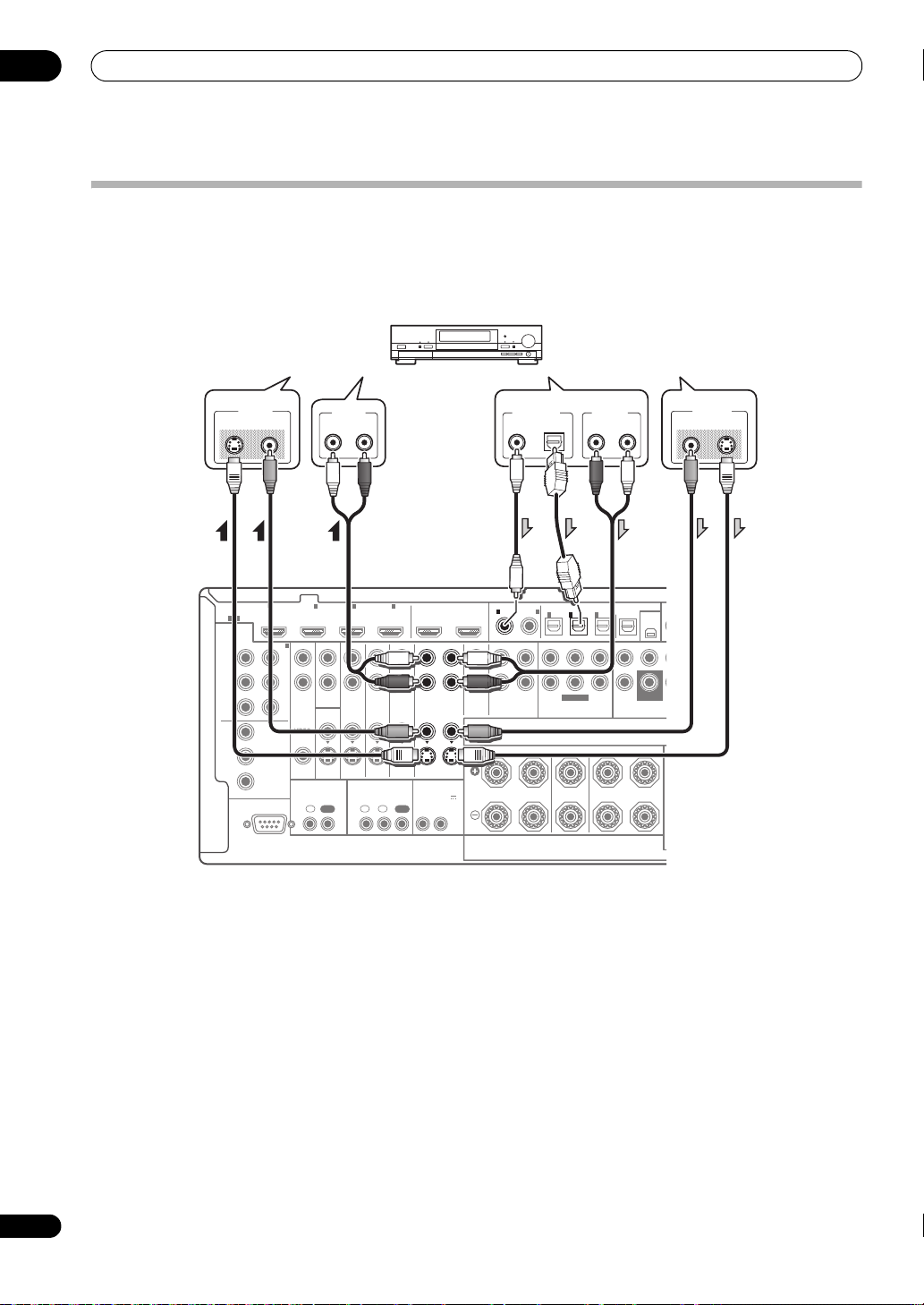
Connecting your equipment
03
28
En
Connecting an HDD/DVD recorder, VCR and other video sources
This receiver has two sets of audio/video inputs and outputs suitable for connecting analog or digital video devices,
including HDD/DVD recorders and VCRs.
When you set up the receiver you’ll need to tell the receiver which input you connected the recorder to (see also The
Input Setup menu on page 43).
RS-232C
COMPONENT
VIDEO
HDMI
ZONE2
VIDEO
S-VIDEO
ASSIGNABLE
ASSIGNABLE
ASSIGNABLE
ASSIGN-
ABLE
MONITOR
OUT
MONITOR
OUT
IN
Y
L
R
P
B
P
R
Y
P
B
P
R
Y
OUT
DVD
IN
TV/SAT
IN
VIDEO DVR
IN
CD
ININOUT
CD-R/TAPE
MULTI CH IN PRE
XM
SPEAKERS
OPTICAL
COAXIAL
INOUT
ZONE3
OUT
P
B
P
R
1
INBD IN
1
IN
2
IN OUT 1 OUT 2
(
KURO
LINK
)
(
DVD
) (
CD
)(
TV/SAT
) (
DVR
) (
VIDEO
)
3
IN
1
IN
1
A
IN
2
IN
OUT
IN
FRONT
R
LR L
CENTER
SURROUND
FRONT CENTER SURROUND FRONT CENTER
S
3
IN
2
1 3
(
DVD
)
IN
2
(
DVR
)
CONTROL IR
12 V TRIGGER
IN IN IN
OUT OUT
12
12
(OUTPUT 12 V
TOTAL 50 mA MAX)
SUBWOOFER
SUBWOOFER
DIGITAL OUT
COAXIAL OPTICAL
ANALOG
RL
ANALOG
RL
AUDIO OUTAUDIO IN
VIDEO OUT
VIDEO S-VIDEO
VIDEO IN
VIDEOS-VIDEO
HDD/DVD recorder, VCR, etc.
Select one
Select one Select one
VSX-23TXH
Connecting your equipment
03
29
En
Connecting a satellite/cable receiver or
other set-top box
Satellite and cable receivers, and terrestrial digital TV
tuners are all examples of so-called ‘set-top boxes’.
When you set up the receiver you’ll need to tell the
receiver which input you connected the set-top box to
(see The Input Setup menu on page 43).
Connecting the multichannel analog
inputs
For DVD Audio and SACD playback, your DVD player may
have 5.1 channel analog outputs. Make sure that the
player is set to output multichannel analog audio.
•If your player has 7.1-channel analog outputs, the
player’s surround back output terminals are not
used. Please refer to the operating instructions
supplied with your component for more information.
Connecting other audio components
This receiver has both digital and analog inputs, allowing
you to connect audio components for playback.
This receiver features five stereo audio-only inputs. One
of these inputs have corresponding outputs for use with
audio recorders.
Most digital components also have analog connections.
2
S-VIDEO
ASSIGNABLE
ASSIGN-
ABLE
MONITOR
OUT
DVD
IN
TV/SAT
IN
VIDEO DVR
IN
CD
ININOUT
CD-R/TAPE
MULTI CH IN PRE
XM
SPEAKERS
OPTICAL
COAXIAL
INOUT
ZONE3
OUT
N
1
IN
2
IN OUT 1 OUT 2
(
KURO
LINK
)
(
DVD
) (
CD
) (
TV/SAT
) (
DVR
)(
VIDEO
)
3
IN
1
IN
1
A
IN
2
IN
OUT
IN
FRONT
R
L RL
CENTER
SURROUND
FRONT CENTER SURROUND FRONT CENTER
3
IN
2
12 V TRIGGER
N IN IN
OUT OUT
12
12
(OUTPUT 12 V
TOTAL 50 mA MAX)
SUBWOOFER
SUBWOOFER
VIDEO OUT
VIDEOS-VIDEO
ANALOG
R
AUDIO OUT
DIGITAL OUT
COAXIAL OPTICAL
L
STB
Select one
Select one
VSX-23TXH
ASSIGNABLE
ASSIGN-
ABLE
DVR CD
ININOUT
CD-R/TAPE
MULTI CH IN PR
E
XM
SPEAKERS
OPTICAL
COAXIAL
INOUT
OUT 1 OUT 2
(
KURO
LINK
)
(
DVD
)(
CD
)(
TV/SAT
)(
DVR
)(
VIDEO
)
IN
1
IN
1
A
IN
2
IN
OUT
IN
FRONT
R
L RL
CENTER
SURROUND
FRONT CENTER SURROUND FRONT CENTER
3
IN
2
12 V TRIGGER
12
(OUTPUT 12 V
TOTAL 50 mA MAX)
SUBWOOFER
SUBWOOFER
RL
FRONT
OUTPUT
RL
SURROUND
OUTPUT
CENTER
OUTPUT
SUBWOOFER
OUTPUT
DVD player, etc.
VSX-23TXH
Connecting your equipment
03
30
En
When you set up the receiver you’ll need to tell the
receiver which input you connected the component to
(see also The Input Setup menu on page 43).
•If your turntable has line-level outputs (i.e., it has a
built-in phono pre-amp), connect it to the CD inputs
instead.
•If you’re connecting a recorder, connect the analog
audio outputs to the analog audio inputs on the
recorder.
About the WMA9 Pro decoder
This unit has an on-board Windows Media™ Audio 9
Professional
1
(WMA9 Pro) decoder, so it is possible to
playback WMA9 Pro-encoded audio using HDMI, coaxial
or optical digital connection when connected to a WMA9
Pro-compatible player. However, the connected DVD
player, set-top b ox, etc. must be abl e t o ou tput WMA9 Pro
format audio signals through a coaxial or optical digital
output.
Connecting additional amplifiers
This receiver has more than enough power for any home
use, but it’s possible to add additional amplifiers to every
channel of your system using the pre-outs. Make the
connections shown below to add amplifiers to power
your speakers.
• You can use the additional amplifier on the surround
back channel pre-outs for a single speaker as well. In
this case plug the amplifier into the left (L (Single))
terminal only.
• The sound from the surround back terminals will
depend on how you have configured the Surround
back speaker setting on page 91.
•To hear sound only from the pre-outs, switch the
speaker system to OFF, or simply disco
nnec
t any
speakers that are connected directly to the receiver.
If you’re not using a subwoofer, change the front speaker
setting (see Speaker Setting on page 91) to LARGE.
Note
1• Windows Media and the Windows logo are trademarks or registered trademarks of Microsoft Corporation in the United States and/or other
countries.
• With WMA9 Pro, sound problems may occur depending on your computer system. Note that WMA9 Pro 96 kHz sources will be
downsampled to 48 kHz.
ASSIGNABLE
ASSIGN-
ABLE
DVR C D
ININOUT
CD-R/TAPE
MULTI CH IN PRE
XM
SPEAKERS
OPTICAL
COAXIAL
INOUT
OUT 1 OUT 2
(
KURO
LINK
)
(
DVD
) (
CD
) (
TV/SAT
)(
DVR
) (
VIDEO
)
IN
1
IN
1
A
IN
2
IN
OUT
IN
FRONT
R
L RL
CENTER
SURROUND
FRONT CENTER SURROUND FRONT CENTER
S
3
IN
2
12 V TRIGGER
12
(OUTPUT 12 V
TOTAL 50 mA MAX)
SUBWOOFER
SUBWOOFER
DIGITAL OUT
COAXIAL OPTICAL
ANALOG
RL
AUDIO OUT
ANALOG
RL
AUDIO IN
DIGITAL IN
OPTICAL
CD-R, MD, DAT, etc.
Select oneSelect one
VSX-23TXH
PRE OUT
SIRIUS
XM
OPTICAL
AUDIO
O
)
(
Single
)
B
OUT
IN
IN
L
SURROUND
R
SURROUND BACK /
ND FRONT CENTER
L
R
SURROUND SURROUND
BACK
SUBWOOFER
R
L
ANALOG
INPUT
R
L
ANALOG
INPUT
R
L
ANALOG
INPUT
ANALOG
INPUT
ANALOG
INPUT
Powered
subwoofer
Front channel
amplifier
Center channel
amplifier (mono)
Surround channel
amplifier
Surround back
channel amplifier
Loading...