


DMH-ZF9350BT DMH-ZS9350BT
DMH-Z6350BT
RDS AV RECEIVER
PENERIMA RDS AV
RDS AV РЕСИВЕР
English
Русский Indonesia
Quick Start Guide
Panduan singkat Руководство по быстрому началу работы

English
This guide is intended to guide you through the basic functions of this unit. For details, please refer to the Operation manual stored on the website.
Indonesia
Panduan ini dibuat untuk memandu Anda memahami fungsi dasar unit ini. Untuk informasi lebih detail, lihat Pedoman Pengoperasian yang tersimpan di dalam situs web.
.
.
- .
https://sg.pioneercarentertainment.com/
https://my.pioneercarentertainment.com/
https://th.pioneercarentertainment.com/
https://id.pioneercarentertainment.com/
http://www.pioneerisrael.co.il/
http://www.pioneerhongkong.com.hk/ct/index.php
http://www.pioneer-twn.com.tw/
https://www.pioneer-rus.ru/
http://pioneer-mea.com/en/
Precaution
 WARNING
Slots and openings in the cabinet are provided for ventilation to ensure reliable operation of the product, and to protect it from overheating. To prevent fire hazard, the openings should never be blocked or covered with items (such as papers, floor mat, cloths).
 CAUTION
This product is evaluated in moderate and tropical climate condition under the Audio, video and similar electronic apparatus - Safety requirements, IEC 60065.
To ensure safe driving
 WARNING
•LIGHT GREEN LEAD AT POWER CONNECTOR IS DESIGNED TO DETECT PARKED STATUS AND MUST BE CONNECTED TO THE POWER SUPPLY SIDE OF THE HANDBRAKE SWITCH. IMPROPER CONNECTION OR USE OF THIS LEAD MAY VIOLATE APPLICABLE LAW AND MAY RESULT IN SERIOUS INJURY OR DAMAGE.
•To avoid the risk of damage and injury and the potential violation of applicable laws, this product is not for use with a video image that is visible to the driver.
•In some countries the viewing of video image on a display inside a vehicle even by persons other than the driver may be illegal. Where such regulations apply, they must be obeyed.
If you attempt to watch video image while driving, the warning “Viewing of front seat video source while driving is strictly prohibited.” will appear on the screen. To watch video image on this display, stop the vehicle in a safe place and apply the handbrake.
Please keep the brake pedal pushed down before releasing the handbrake.
Getting started
 Touch
Touch  Touch and hold
 Swipe
Swipe
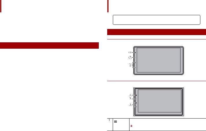
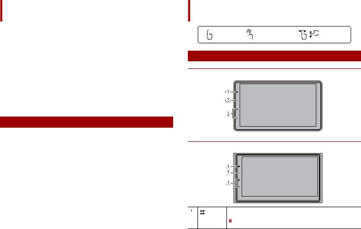
What’s What
DMH-ZF9350BT/DMH-ZS9350BT
DMH-Z6350BT
 Display the top menu screen
 Power off
2 En
 Activate the voice recognition mode
 Display mobile device search or select screen
/
Volume
Starting up the unit
1 |
language |
|
location if required |
|
[Network Mode] or |
|
|
||||
|
[Standard Mode] |
|
|
|
|
 WARNING
Do not use the unit in Standard Mode when a speaker system for 3-way Network Mode is connected to the unit. This may cause damage to the speakers.
2  [OK]
[OK]  [OK]
[OK]
Wi-Fi connection
 WARNING
•Do not attempt to operate the web browser while driving. Make sure to pull off the road and park your vehicle in a safe location before attempting to use the controls on the web browser.
•When you use the browser, do not enter your important information such as credit card information, bank account information and personal information.
•When you use the browser, do not install the software or programme that Pioneer is not involved with. If you install such software or programme, you may suffer from damages such as mechanical trouble or put your entered information in danger.
1 |
|
|
|
screen |
||||
|
|
|
||||||
2 |
|
|
|
[Wi-Fi Settings] [Access point setting] |
|
|
||
|
|
|
|
|
||||
|
|
|
|
|
|
|
|
|
Bluetooth® connection |
||||||||
1 |
|
|
|
screen |
||||
|
|
|
||||||
2 |
|
|
|
[Connection] |
|
|
||
|
|
|
|
|
||||
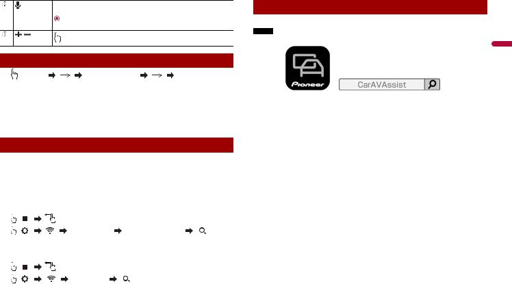
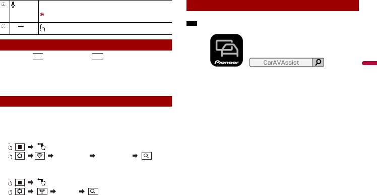
CarAVAssist
Using CarAVAssist anytime, anywhere, optimise and expand your in-car and daily life.
NOTE
CarAVAssist must be connected to this unit in order to synchronise the changes. |
|
Download Now |
English |
|
|
CarAVAssist is an application that allows you to configure and transfer various settings of |
|
this unit and register URLs as favourites so that you can browse them using this unit’s |
|
web browser. |
|
En 3
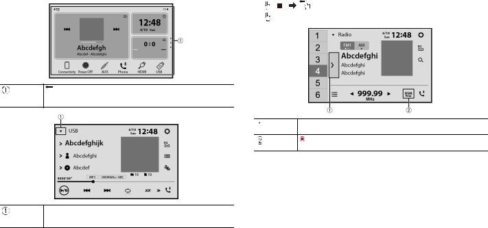
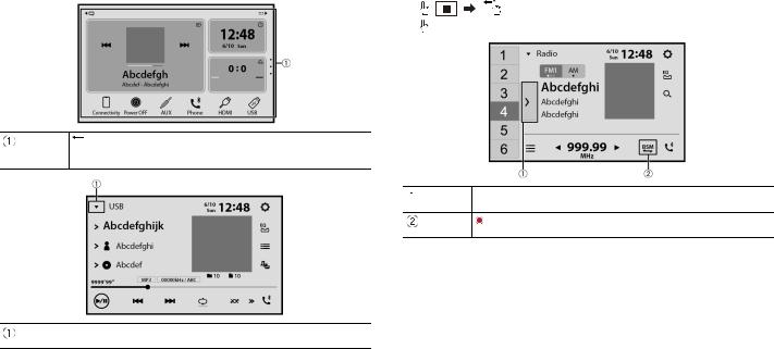
Selecting the source/application |
|
Tuner operation |
|||
|
1 |
|
|
screen |
|
|
|
|
|||
|
2 |
[Radio] |
|||
 Display the source/application selection screen and select a source/application
 Display the source/application list and select a source/ application
 Display the preset channel list
 Store the strongest broadcast frequencies
4 En
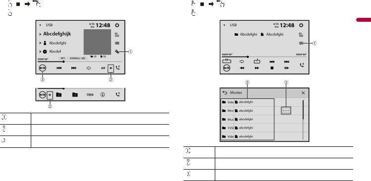
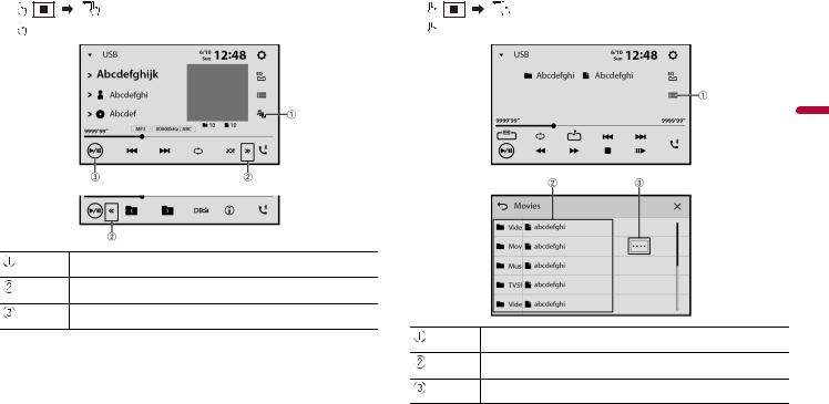
Audio operation |
|
Video operation |
||||||
1 |
|
|
screen |
1 |
|
|
screen |
|
|
|
|
|
|||||
2 |
audio source |
2 |
video source |
|||||
English
 Switch between media file types
 Display the hidden function bar
 Pause and start playback
 Display the playlist screen
 Select a list title that you want to play
 Scroll the list title or category name
En 5
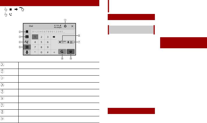
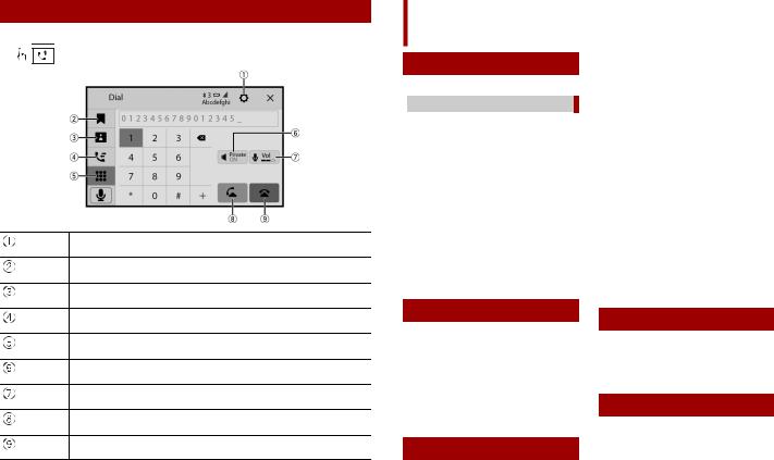
Bluetooth telephone operation
1 |
|
screen |
|
||
2 |
|
|
|
|
 Display the Bluetooth connection menu
 Display the preset dial screen
 Switch to the phone book mode
 Switch to the call history list
 Enter the phone number directly
 Turn private mode on and off
 Adjust the talking volume
 Make an outgoing call
 End a call
6 En
Connection
Precautions
Your new product and this manual
•Do not operate this product, any applications, or the rear view camera option (if purchased) if doing so will divert your attention in any way from the safe operation of your vehicle. Always observe safe driving rules and follow all existing traffic regulations. If you experience difficulty in operating this product, pull over, park your vehicle in a safe location and apply the handbrake before making the necessary adjustments.
•Do not install this product where it may
(i)obstruct the driver’s vision,
(ii)impair the performance of any of the vehicle’s operating systems of safety features, including airbags, hazard lamp buttons, or
(iii)impair the driver’s ability to safely operate the vehicle.
In some cases, it may not be possible to install this product because of the vehicle type or the shape of the vehicle interior.
Important safeguards
 WARNING
Pioneer does not recommend that you install this product yourself. This product is designed for professional installation only. We recommend that only authorised Pioneer service personnel, who have special training and experience in mobile
electronics, set up and install this product. NEVER SERVICE THIS PRODUCT YOURSELF. Installing or servicing this product and its connecting cables may expose you to the risk of electric shock or other hazards, and can cause damage to this product that is not covered by warranty.
Precautions before connecting the system
 CAUTION
•Secure all wiring with cable clamps or electrical tape. Do not allow any bare wiring to remain exposed.
•Do not directly connect the yellow lead of this product to the vehicle battery. If the lead is directly connected to the battery, engine vibration may eventually cause the insulation to fail at the point where the wire passes from the passenger compartment into the engine compartment. If the yellow lead’s insulation tears as a result of contact with metal parts, short-circuiting can occur, resulting in considerable danger.
•It is extremely dangerous to allow cables to become wound around the steering column or gearstick. Be sure to install this product, its cables, and wiring away in such so that they will not obstruct or hinder driving.
•Make sure that the cables and wires will not interfere with or become caught in any of the vehicle’s moving parts, especially the steering wheel, gearstick, handbrake, sliding seat tracks, doors, or any of the vehicle’s controls.
•Do not route wires where they will be exposed to high temperatures. If the insulation heats up, wires may become damaged, resulting in a short circuit or malfunction and permanent damage to the product.
•Do not shorten any leads. If you do, the protection circuit (fuse holder, fuse resistor or filter, etc.) may fail to work properly.
•Never feed power to other electronic products by cutting the insulation of the power supply lead of this product and tapping into the lead. The current capacity of the lead will be exceeded, causing overheating.
Before installing this product
•Use this unit with a 12-volt battery and negative earthing only. Failure to do so may result in a fire or malfunction.
•To avoid shorts in the electrical system, be sure to disconnect the (–) battery cable before installation.
To prevent damage
 WARNING
•When speaker output is used by 4 channels , use speakers over 50 W (Maximum input power) and between 4
Ωto 8 Ω (impedance value). Do not use 1
Ωto 3 Ω speakers for this unit.
•When rear speaker output is used by 2 Ω of subwoofer, use speakers over 70 W (Maximum input power).
*Please refer to connection for a connection method.
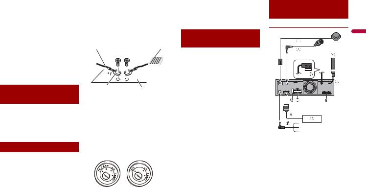
•The black lead is earth. When installing this unit or power amp (sold separately), make sure to connect the earth wire first. Ensure that the earth wire is properly
connected to metal parts of the car’s body. The earth wire of the power amp and the one of this unit or any other device must be connected to the car separately with different screws. If the screw for the earth wire loosens or falls out, it could result in fire generation of smoke or malfunction.
Earth wire |
POWER AMP |
Other devices |
|
|
|
Metal parts of car’s |
|||
(Another electronic |
body |
||
device in the car) |
|
|
|
*1 Not supplied for this unit
•When replacing the fuse, be sure to only use a fuse of the rating prescribed on this product.
•When disconnecting a connector, pull the connector itself. Do not pull the lead, as you may pull it out of the connector.
•This product cannot be installed in a vehicle without ACC (accessory) position on the ignition switch.
ACC position |
No ACC position |
•To avoid short-circuiting, cover the disconnected lead with insulating tape. It is especially important to insulate all unused speaker leads, which if left uncovered may cause a short circuit.
•For connecting a power amp or other devices to this product, refer to the manual for the product to be connected.
•The graphical symbol  placed on the product means direct current.
Notice for the blue/ white lead
•When the ignition switch is turned on (ACC ON), a control signal is output through the blue/white lead. Connect to an external power amp’s system remote control terminal, the auto-aerial relay control terminal, or the aerial booster power control terminal (max. 300 mA 12 V DC). The control signal is output through the blue/white lead, even if the audio source is switched off.
 Important
When this product is in [Power OFF] mode, the control signal is also turned off. If [Power OFF] mode is cancelled, the control signal is output again and the aerial is extended with the auto aerial function (if the aerial is being used). Be careful so that the extended aerial does not come into contact with any obstacles.
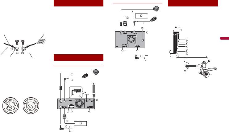
Rear panel (main terminals)
DMH-ZF9350BT/DMH-ZS9350BT
English
En 7
DMH-Z6350BT |
Power cord |
|
|
|
WARNING |
|
IMPROPER CONNECTION MAY RESULT IN |
|
SERIOUS DAMAGE OR INJURY |
|
INCLUDING ELECTRICAL SHOCK, AND |
|
INTERFERENCE WITH THE OPERATION |
|
OF THE VEHICLE'S ANTILOCK BRAKING |
|
SYSTEM, AUTOMATIC TRANSMISSION |
|
AND SPEEDOMETER INDICATION. |
 GPS aerial 3.55 m
 Microphone 3 m
 Monitor cable connector* Connect to LCD screen.
 Aerial jack
 This product
 Pre out supply
 Power supply
 Fuse (10A)
 RGB cable (supplied with Navigation system or Hideaway TV tuner)
 Pioneer navigation system or Hideaway TV tuner
Contact your dealer to inquire about the connectable navigation unit.
 Wired remote input
Connect to steering wheel control interface of your vehicle. For more details, consult your dealer.
*Monitor cable and connector are in the front panel. (DMH-ZF9350BT)
8 En
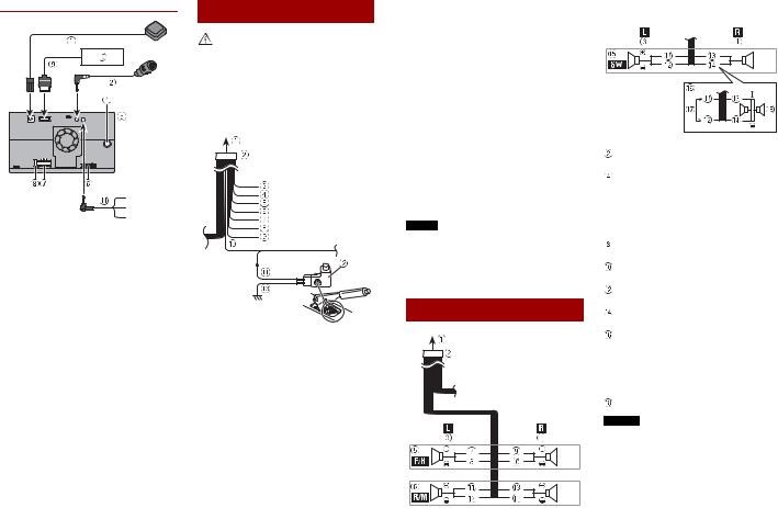
 To power supply
 Power cord
 Yellow
To terminal supplied with power regardless of ignition switch position.
 Red
Red
To electric terminal controlled by ignition switch (12 V DC) ON/OFF
 Orange/white
To lighting switch terminal.  Black (earth)
To vehicle (metal) body.  Violet/white
Of the two lead wires connected to the back lamp, connect the one in which the voltage changes when the gear shift is in the REVERSE (R) position. This
connection enables the unit to sense whether the car is moving forwards or backwards.
 Pink
Pink
Car speed signal input  Blue/white
Connect to system control terminal of the power amp (max. 300 mA 12 V DC).
 Light green
Used to detect the ON/OFF status of the handbrake. This lead must be connected to the power supply side of the handbrake switch.
If this connection is made incorrectly or omitted, certain functions of this product will be unusable.
 Power supply side
 Handbrake switch
  Earth side
NOTE
The position of the speed detection circuit and the position of the handbrake switch vary depending on the vehicle model. For details, consult your authorised Pioneer dealer or an installation professional.
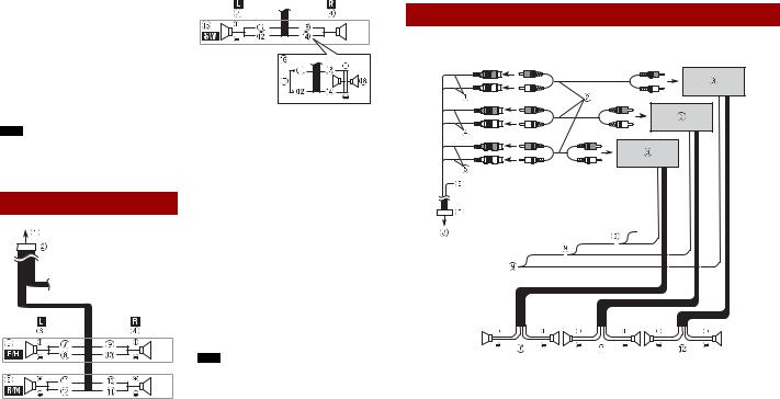
Speaker leads
Perform these connections when using a subwoofer without the optional amplifier.
 To power supply
Power cord
 Left
Left
Right
 Front speaker (STD) or high range speaker (NW)
 Rear speaker (STD) or middle range speaker (NW)
 White
White
White/black
 Grey
Grey
Grey/black
 Green
Green
Green/black
 Violet
Violet/black
 Subwoofer (4 Ω)
When using a subwoofer of 2 Ω, be sure to connect the subwoofer to the violet and violet/black leads of this unit. Do not connect anything to the green and green/black leads.
 Not used. Subwoofer (4 Ω) × 2
NOTES
•When a subwoofer is connected to this product instead of a rear speaker, change the rear output setting in the initial setting. The subwoofer output of this product is monaural.
For details, refer to the Operation Manual.
•With a two-speaker system, do not connect anything to the speaker leads that are not connected to speakers.
Power amp (sold separately)
 Important
The speaker leads are not used when this connection is in use.
English
 Subwoofer output (SUBWOOFER OUTPUT) 23 cm (STD) Low range output (NW)
 RCA cable (sold separately)
 Power amp
 Front output (FRONT OUTPUT) 15 cm (STD) High range output (NW)
 Rear output (REAR OUTPUT) 15 cm (STD) Middle range output (NW)
 Yellow/black (MUTE)
If you use an equipment with Mute function, wire this lead to the Audio Mute lead on that equipment. If not, keep the Audio Mute lead free of any connections.
 Pre out cord
 To pre out supply
 System remote control
Connect to Blue/white cable (max. 300 mA 12 V DC).
En 9
 Rear speaker (STD)
Middle range speaker (NW)
 Front speaker (STD)
High range speaker (NW)
 Subwoofer (STD)
Low range speaker (NW)
NOTE
Select the appropriate speaker mode between standard mode (STD) and network mode (NW). For details, refer to the Operation Manual.
10En
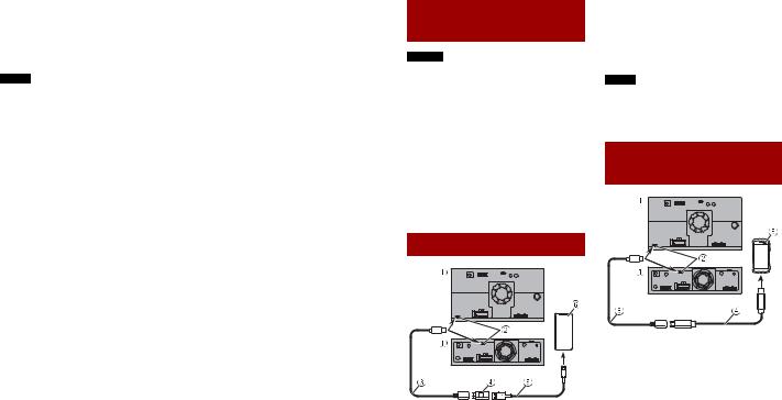
iPhone® and smartphone
NOTES
•For details on how to connect an external device using a separately sold cable, refer to the manual for the cable.
•For details concerning the connection, operations and compatibility of the iPhone, refer to the Operation Manual.
•For details concerning the connection and operations of the smartphone, refer to the Operation Manual.
•The supplied USB Type-C® cable and the USB Type-C to USB Type-A adaptor are for connecting a USB storage device to this unit only. Do not use the cable and the adaptor for other products or purposes.
iPhone
 This product
 USB Type-C port
 USB Type-C cable 1.5 m
 USB Type-C to USB Type-A adaptor
 USB interface cable for iPhone (CD-IU52) (sold separately)
 iPhone
TIP
When a USB Type-C to Lightning® connector cable (Apple Inc. product) (sold separately) is used to connect this unit to an iPhone that supports USB-PD, quick charging is performed for the iPhone.
NOTE
When you use a USB Type-C to Lightning connector cable (Apple Inc. product) (sold separately), follow the instructions provided with the cable.
Smartphone (Android™ device)
 This product
 USB Type-C port
 USB Type-C cable 1.5 m
 USB Type-C to USB Type-C interface cable (CD-CCU500) (sold separately)
  Smartphone
TIPS
•Use the supplied USB Type-C to USB Type-A adaptor with a USB Type-A to micro USB B cable (CD-MU200) (sold separately) if your smartphone has a micro USB B port.
•When a USB Type-C to USB Type-C cable (sold separately) is used to connect this unit to a smartphone, quick charging is performed.
NOTE
If you use a cable other than those suggested in the illustration, the main unit may not function properly.
Camera
When you use the rear view camera, the rear view image is automatically switched from the video by moving the gearstick to
REVERSE (R). Camera View mode also allows you to check what is behind you while driving.
 WARNING
USE INPUT ONLY FOR REVERSE OR MIRROR IMAGE REAR VIEW CAMERA. OTHER USE MAY RESULT IN INJURY OR DAMAGE.
 CAUTION
•The screen image may appear reversed.
•With the rear view camera you can keep an eye on trailers, or back into a tight parking spot. Do not use for entertainment purposes.
•Objects in rear view may appear closer or more distant than in reality.
•The image area of full-screen images displayed while backing or checking the rear of the vehicle may differ slightly.
 This product
 Pre out supply
 Power supply
 To pre out supply
 To power supply
 Pre out cord
 Power cord
 Violet/white (REVERSE-GEAR SIGNAL INPUT)
 Brown (REAR VIEW CAMERA IN) 23 cm
 Yellow (SECOND CAMERA INPUT) 23 cm
 Rear view camera (ND-BC8) (sold separately)
 To video output
 RCA power supply cable (supplied with ND-BC8)
 RCA cable (sold separately)
 View camera (sold separately)
NOTES
•Connect only the rear view camera to brown cable. Do not connect any other equipment.
•Some appropriate settings are required to use rear view cameras. For details, refer to the Operation Manual.
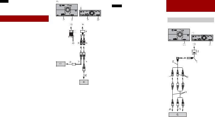
External video component
 Using an AUX input


 English
 This product
 Pre out supply
 To pre out supply
 Pre out cord
 AUX input (AUX IN) 15 cm
 Mini-jack AV cable (sold separately)
 Yellow
 Red, white
En 11
 RCA cables (sold separately)
 To video output
 To audio output
 External video component (sold separately)
NOTE
The appropriate setting is required to use the external video component. For details, refer to the Operation Manual.
 CAUTION
Be sure to use a mini-jack AV cable (sold separately) for wiring. If you use other cables, the wiring position might differ resulting in disturbed images and sounds.
L : Left audio (White)
R : Right audio (Red)
V : Video (Yellow)
G : Earth
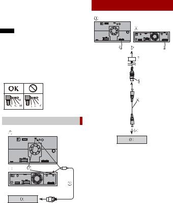
 Using an HDMI input
 This product
 Micro HDMI port
 Micro HDMI to HDMI cable (sold separately)
 HDMI device (sold separately)
Rear display
 This product
 Pre out supply
 To pre out supply
 Pre out cord
 Yellow (REAR MONITOR OUTPUT) 30 cm
 RCA cable (sold separately)
 To Video input
 Rear display with RCA input (sold separately)
 WARNING
NEVER install the rear display in a location that enables the driver to watch the video source while driving.
This product’s rear video output is for connection of a display to enable
passengers in the rear seats to watch the video source.
12En
Installation
Precautions before installation
 CAUTION
•Never install this product in places where, or in a manner that:
–Could injure the driver or passengers if the vehicle stops suddenly.
–May interfere with the driver’s operation of the vehicle, such as on the floor in front of the driver’s seat, or close to the steering wheel or gearstick.
•To ensure proper installation, be sure to use the supplied parts in the manner specified. If any parts are not supplied with this product, use compatible parts in the manner specified after you have the part compatibility checked by your dealer. If parts other than supplied or compatible ones are used, they may damage internal parts of this product or they may work loose and the product may become detached.
•It is extremely dangerous to allow cables to become wound around the steering column or gearstick. Be sure to install this product, its cables, and wiring away in such so that they will not obstruct or hinder driving.
•Make sure that leads cannot get caught in a door or the sliding mechanism of a seat, resulting in a short circuit.
•Please confirm the proper function of your vehicle’s other equipment after installation of this product.
•Do not install this product where it may
(i) obstruct the driver’s vision,
(ii) impair the performance of any of the vehicle’s operating systems or safety
features, including airbags, hazard lamp buttons or
(iii) impair the driver’s ability to safely operate the vehicle.
•Never install this product in front of or next to the place in the dashboard, door, or pillar from which one of your vehicle’s airbags would deploy. Please refer to your vehicle’s owner’s manual for reference to the deployment area of the frontal airbags.
Before installing
•Consult with your nearest dealer if installation requires drilling holes or other modifications of the vehicle.
•Before making a final installation of this product, temporarily connect the wiring to confirm that the connections are correct and the system works properly.
Installation notes
•Do not install this product in places subject to high temperatures or humidity, such as:
–Places close to a heater, vent or air conditioner.
–Places exposed to direct sunlight, such as on top of the dashboard.
–Places that may be exposed to rain, such as close to the door or on the vehicle’s floor.
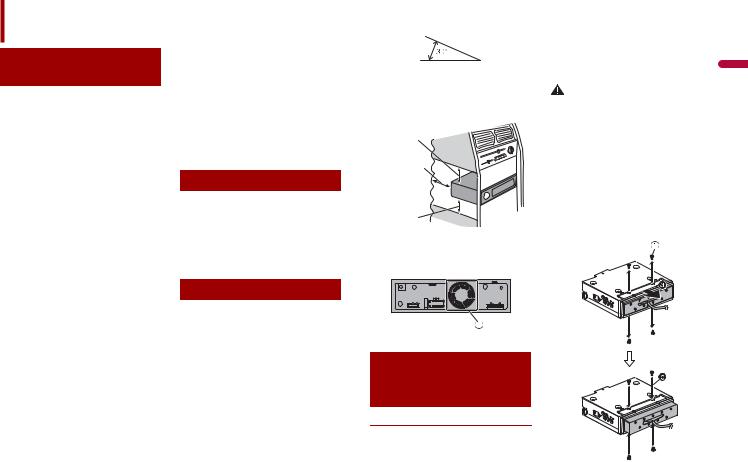
•Install this product horizontally on a surface within 0 to 30 degrees tolerance (within 5 degrees to the left or right). Improper installation of the unit with the surface tilted more than these tolerances increases the potential for errors in the
vehicle’s location display, and might otherwise cause reduced display performance.
•When installing, to ensure proper heat dispersal when using this unit, make sure you leave ample space behind the rear panel and wrap any loose cables so they are not blocking the vents.
5 cm
Leave ample space
5 cm
•The cords must not cover up the area shown in the figure below. This is necessary to allow the amplifiers to radiate freely. (DMH-ZS9350BT)
 Do not cover this area
Installation using the screw holes on the side of this product
DMH-ZF9350BT
Installation tips
The following procedure describes how to install this product with an LCD screen attached to the unit. Depending on the
vehicle or installation location, you may |
|
need to adjust the mounting position of |
|
the LCD screen in order to prevent |
|
impairment of vehicle driving operations. |
|
For details on the mounting LCD screen |
|
dimensions, refer to The adjusting position |
|
and mounting dimension of the display |
English |
WARNING |
|
(page 17) before installing. |
|
Do not use a mounting sleeve to install this unit to prevent it from popping out or rattling.
1Adjust the front-back position of the front panel by removing the flush surface screws on the front edge of the
unit ( ) then fix the face panel by using the screw (
 ) (optional).
Depending on the vehicle, the frontback position of the front panel may need to be adjusted to mount the LCD screen. Slide the face panel to the front before installing the unit to the vehicle.
 Screw
Screw
En 13

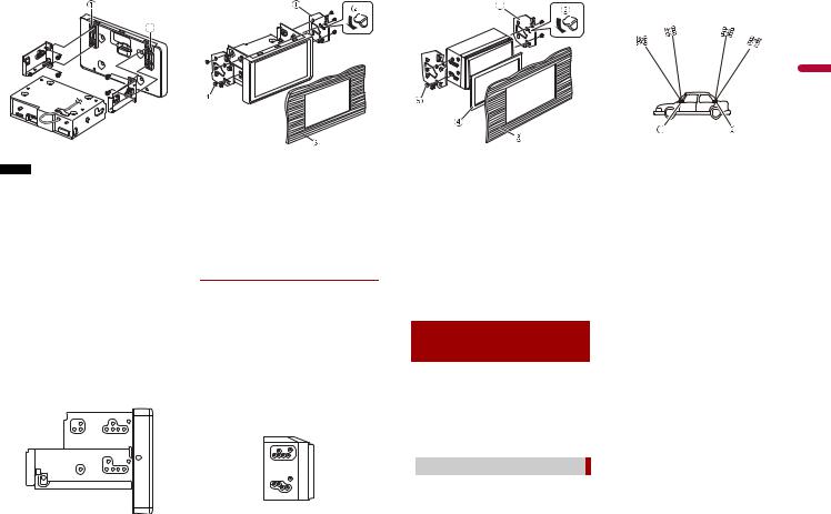
2Fasten this product to the factory radio-mounting bracket.
Position this product so that its screw holes are aligned with the screw holes of the bracket, and tighten the screws at three locations on each side.
TIP
The amount of this unit's protrusion from the dashboard/console can be adjusted by shifting the position of the screw hole of this unit to the factory radio-mounting bracket.
 Factory radio-mounting bracket
 If the pawl interferes with installation, you may bend it down out of the way.
 Dashboard or console
 Binding head screw (8 mm)
Be sure to use the screws supplied with this product.
3Fasten the LCD screen mounting bracket to the main unit at the suitable position.
 LCD screen mounting bracket
  Binding head screw (4 mm × 6 mm)
TIP
The mounting left-centre-right position of the LCD screen mounting bracket can be changed depending on the vehicle or installation location of the main unit.
4Detach the monitor cable cover from
the LCD screen ( ), then connect the monitor cable to the LCD screen (
 ). After that, attach the LCD screen with
adjusting the up-down position ( ) to this unit by using the screws each side (
 ).
).
14En
 Monitor cover
 Binding head screw (4 mm × 12 mm)
5Secure the monitor cable to the hook on the back of the LCD screen then
attach the monitor cover ( ) by using the screws (
 ).
).
 Monitor cover
 Machine screw (2 mm × 4 mm)
DMH-ZS9350BT
Installation tips
The following procedure describes how to use the supplied parts to install this product with the LCD screen attached to the unit. It is also possible to install this product so that the LCD screen is separate
from the unit. For details, visit the Pioneer website for your region.
For some types of vehicles, it is necessary to use an installation kit (sold separately) when installing. For details, visit the Pioneer website for your region.
1First attach the supplied side brackets to the LCD screen ( ), then attach them to this unit (
  ). After that, connect the monitor cable to the LCD screen (
  ).
).
 Side bracket (for attaching LCD screen to unit)
 Binding head screw (5 mm)
Be sure to use the screws supplied with this product.
 Monitor cable
Attach the monitor cable to the unit with heat resistant tape (sold separately).
Some vehicles require the use of special parts. Refer to the following illustration when installing.
 Special parts (including screws)
NOTE
For details on the types of vehicles that require special parts, visit the Pioneer website for your region.
2Fasten this product to the factory radio-mounting bracket.
Position this product so that its screw holes are aligned with the screw holes of the bracket, and tighten the screws at three locations on each side.
Use either the binding head screws or flush surface screws, depending on the shape of the bracket’s screw holes.
TIP
The amount of this unit's protrusion from the dashboard/console can be adjusted by shifting the position of the screw hole of this unit to the factory radio-mounting bracket.
 Factory radio-mounting bracket
 If the pawl interferes with installation, you may bend it down out of the way.
 Dashboard or console
 Binding head screw (8 mm)
Be sure to use the screws supplied with this product.
DMH-Z6350BT
1Fasten this product to the factory radio-mounting bracket.
Position this product so that its screw holes are aligned with the screw holes of the bracket, and tighten the screws at three locations on each side.
TIP
The amount of this unit's protrusion from the dashboard/console can be adjusted by shifting the position of the screw hole of this unit to the factory radio-mounting bracket.
 Factory radio-mounting bracket
 If the pawl interferes with installation, you may bend it down out of the way.
 Dashboard or console
 Frame
Frame
In some types of vehicles, discrepancy may occur between the unit and the dashboard. If this happens, use the supplied frame to fill the gap.
 Truss head screw
Be sure to use the screws supplied with this product.
Installing the GPS aerial
 CAUTION
Do not cut the GPS aerial lead to shorten it or use an extension to make it longer. Altering the aerial cable could result in a short circuit or malfunction and permanent damage to this product.
 Installation notes
•The aerial should be installed on a level surface where radio waves will be blocked as little as possible. Radio waves
cannot be received by the aerial if reception from the satellite is blocked.
English
 Dashboard
 Rear shelf
•When installing the GPS aerial inside the vehicle, be sure to use the metal sheet provided with your system. If this is not used, the reception sensitivity will be poor.
•Do not cut the accessory metal sheet. This would reduce the sensitivity of the GPS aerial.
•Take care not to pull the aerial lead when removing the GPS aerial. The lead may become detached.
•Do not paint the GPS aerial, as this may affect its performance.
En 15
When installing the aerial inside the vehicle (on the dashboard or rear shelf)
 WARNING
Do not install the GPS aerial over any sensors or vents on the dashboard of the vehicle, as doing so may interfere with the proper functioning of such sensors or vents and may compromise the ability of the metal sheet under the GPS aerial to properly and securely affix to the dashboard.
Make sure the surface is free of moisture, dust, grime, oil, etc., before affixing the metal sheet.
 GPS aerial
 Metal sheet
Peel off the protective sheet on the rear.  Double-sided tape
 Clamps
Use clamps to secure the lead where necessary inside the vehicle.
NOTES
•Affix the metal sheet on the surface as level as possible where the GPS aerial faces the window.
•Affix the GPS aerial on the metal sheet using the double-sided tape.
•The metal sheet contains a strong adhesive which may leave a mark on the surface if it is removed.
•When attaching the metal sheet, do not cut it into small pieces.
•Some models use window glass that does not allow signals from GPS satellites to pass through. On such models, install the GPS aerial on the outside of the vehicle.
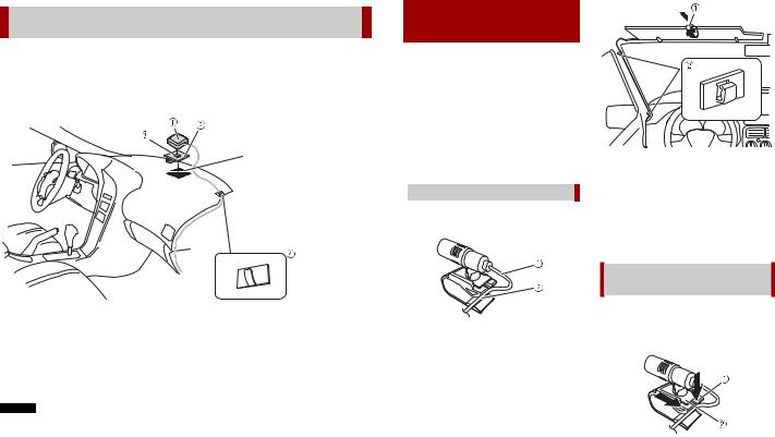
Installing the microphone
•Install the microphone in a place where its direction and distance from the driver make it easiest to pick up the driver’s voice.
•Be sure to turn off (ACC OFF) the product before connecting the microphone.
•Depending on the vehicle model, the microphone cable length may be too short when you mount the microphone on the sun visor. In such cases, install the microphone on the steering column.
 Mounting on the sun visor
1Fit the microphone lead into the groove.
 Microphone lead
 Groove
2Attach the microphone clip to the sun visor.
 Microphone clip
 Clamps
Use separately sold clamps to secure the lead where necessary inside the vehicle.
Install the microphone on the sun visor when it is in the up position. It cannot recognise the driver’s voice if the sun visor is in the down position.
Installation on the steering column
1Detach the microphone base from the microphone clip by sliding the microphone base while pressing the tab.
 Tab
Tab
 Microphone base
2Mount the microphone on the steering column.
16En
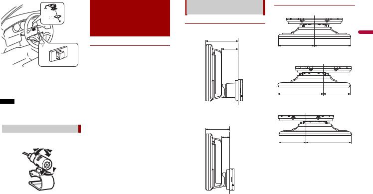
 Double-sided tape
 Clamps
Use separately sold clamps to secure the lead where necessary inside the vehicle.
NOTE
Install the microphone on the steering column, keeping it away from the steering wheel.
 Adjusting the microphone angle
The microphone angle can be adjusted.
The adjusting position and mounting dimension of the display
DMH-ZF9350BT
The mounting position of this unit’s display can be adjusted (front-back/up-down/ right-left/angle). When mounting the display, adjust the mounting position and dimensions so that your view is clear and it does not impair your driving.
 WARNING
Make sure that none of the following conditions exist when mounting the display. Otherwise, an accident may occur.
•It impairs the operation of the steering wheel and levers (gearstick, windscreen wiper switch, turn signal switch, etc.).
•It impairs the operation of the airbags.
•It significantly impairs the operation of the hazard switch.
•It impairs the ability to identify or operate other control switches.
•You are unable to see gauges, metres or warning indicators.
•It interferes with in-vehicle devices (switches, panel, glove box, cup holder,
etc.).
Depending on the vehicle, the display may hinder access to the glove box or cup holder, or it may block the air conditioner vents.
Display mounting dimensions and adjustable positions
Front-back position
Front
75
38.1
mm
Back
55
18.1
mm
Left-right position
Centre
115.4115.4
mm
Left
145.485.4
mm
Right
85.4145.4
mm
English
En 17
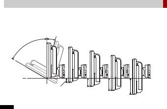
 Adjustable display angles and up-down positions
 WARNING
Keep hands and fingers clear of this product when adjusting the LCD screen angle. Be especially cautious of children’s hands and fingers.
15˚
60˚
15 |
30 |
45 |
60 |
|
|||
|
|
mm
NOTE
Certain positions cannot be adjusted and held depending on the up-down position and the front-back position. For details, refer to Mounting dimension with the angle range of the display (page 19).
18En
 Mounting dimension with the angle range of the display
Front angle range
|
Angle range of front position |
|
|
|
B |
|
A |
|
|
A |
B |
0 |
60˚ |
|
-15 |
|
|
-30 |
|
|
|
35˚ |
-15˚ |
-45 |
|
|
-60 |
|
|
|
|
mm |
|
|
Angle 60˚ |
|
|
Angle 35˚ |
|
|
Angle -15˚ |
|
||||||
|
|
|
|
|
|
|
|
A’ |
|
|
|
|
|
|
A’ |
|
|
|
A’ |
|
|
|
|
|
|
|
|
|
|
|
|
|
|
|
|
|
C |
|
|
|
C |
|
|
A |
|
|
C |
|
|
|
|
|
|
A |
|
|
|
|
|
|
|
|
English |
|
A |
|
|
|
|
|
|
|
|
|
|
|
|
|
|
|
|
B |
|
|
B’ |
|
B |
|
B’ |
|
B |
|
B’ |
|
|
|
|
|
|
|
|
|
|
|
|
|
|||||
|
A |
A’ |
B |
B’ |
C |
A |
A’ |
B |
B’ |
C |
A |
A’ |
B |
B’ |
C |
0 |
50.6 |
152.6 |
-14.8 |
39.4 |
33.4 |
94.6 |
128.4 |
-12.5 |
53.4 |
35.9 |
134.1 |
38.6 |
7.7 |
72.4 |
14.3 |
-15 |
|
|
|
|
|
82.3 |
119.8 |
-24.8 |
44.8 |
27.3 |
119.6 |
42.5 |
-6.8 |
76.3 |
18.2 |
-30 |
|
|
|
|
|
70.1 |
111.2 |
-37.1 |
36.2 |
18.7 |
105.1 |
46.3 |
-21.2 |
80.2 |
22.1 |
-45 |
|
|
|
|
|
57.8 |
102.6 |
-49.4 |
27.6 |
10.1 |
90.6 |
50.2 |
-35.7 |
84.1 |
26.0 |
-60 |
|
|
|
|
|
45.5 |
94.0 |
-61.7 |
19.0 |
1.5 |
76.1 |
54.1 |
-50.2 |
88.0 |
29.9 |
|
|
|
|
|
|
|
|
|
|
|
|
|
|
|
mm |
En 19
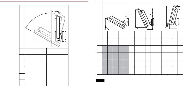
Back angle range
|
Angle range of back position |
|
|
|
B |
|
A |
|
|
A |
B |
0 |
60˚ |
|
-15 |
|
|
-30 |
|
|
|
25˚ |
-15˚ |
-45 |
|
|
-60 |
|
|
|
|
mm |
|
Angle 60˚ |
|
|
Angle 25˚ |
|
|
Angle -15˚ |
|
||||||
|
|
|
|
|
|
|
|
A’ |
|
|
|
|
|
A’ |
|
|
|
|
|
|
|
|
|
|
|
|
|
|
|
|
|
A’ |
|
C |
|
|
|
C |
|
|
|
|
|
C |
|
|
|
|
|
|
|
|
|
|
A |
|
|
|
|
|
|
|
|
|
A |
|
|
|
|
|
|
|
|
|
|
|
|
|
|
|
|
|
|
|
|
|
|
|
|
A |
|
|
|
|
|
|
|
|
|
|
|
|
|
|
|
B |
|
|
B’ |
|
|
B |
B’ |
|
|
B |
|
B’ |
|
|
|
|
|
|
|
|
|
|
|
|||||
|
|
|
|
|
|
|
|
|
|
|
|
|
||
A |
A’ |
B |
B’ |
C |
A |
A’ |
B |
B’ |
C |
A |
A’ |
B |
B’ |
C |
0 50.6 |
132.6 |
-14.8 |
19.4 |
13.4 |
108.6 |
93.8 |
-9.9 |
38.5 |
16.7 |
134.1 |
18.6 |
7.7 |
52.4 |
-5.7 |
-15 |
|
|
|
|
95.0 |
87.5 |
-23.5 |
32.2 |
10.4 |
119.6 |
22.5 |
-6.8 |
56.3 |
-1.8 |
-30 |
|
|
|
|
81.4 |
81.1 |
-37.1 |
25.8 |
4.1 |
105.1 |
26.3 |
-21.2 |
60.2 |
2.1 |
-45 |
|
|
|
|
67.8 |
74.8 |
-50.7 |
19.5 |
-2.3 |
90.6 |
30.2 |
-35.7 |
64.1 |
6.0 |
-60 |
|
|
|
|
54.2 |
68.4 |
-64.3 |
13.2 |
-8.6 |
76.1 |
34.1 |
-50.2 |
68.0 |
9.9 |
|
|
|
|
|
|
|
|
|
|
|
|
|
|
mm |
NOTES
•Where there are no numbers in the table, this indicates that the display cannot be adjusted and held with that angle and dimensions.
•The displayed angle range is the movable range of this unit, and it may vary depending on the vehicle in which the unit is installed.
20En

English
En 21
RoHS ”(CNS 15663)”.
” ”
URL: http://www.pioneer-twn.com.tw/p7-download2.asp


•- IEC 60065
• 並改善至無干擾時方得繼續使用。
低功率射頻電機須忍受合法通信或工業、科學及醫療用電波輻射性電機設備之干擾。

車。請在放開手煞車之前先踩住煞車踏板。
|
|
|
DMH-ZF9350BT/DMH-ZS9350BT
DMH-Z6350BT


2 Zhtw


 /
/
1 


 [ ] [ ]

3
2  [ ]
[ ]  [ ]
[ ]
Wi-Fi

• 路邊的安全位置。
•Pioneer
1 |
|
|
2 |
[Wi-Fi ] |
[ ] |
|
|
|
Bluetooth® |
|
|
1 |
|
|
2 |
[ ] |
|
CarAVAssist
CarAVAssist
CarAVAssist
CarAVAssist URL
Zhtw 3
/ |
|
|
|
|
1 |
|
|
|
2 |
[Radio] |
|
 / /
/ /


 / /
/ /
4 Zhtw
|
|
|
||
1 |
|
1 |
|
|
2 |
|
2 |
|
|


Zhtw 5
Bluetooth
1 


2
 Bluetooth


6 Zhtw

• 行必要調整。
i ii
iii

Pioneer

• 而導致相當大的危險。
• 檔桿、手煞車、座椅滑軌、車門或任何 車輛操控裝置。
• 路或造成產品故障及永久性損壞。
•12
• 拔下(-)

•4 50 W 4 Ω 8 Ω 1 Ω 3 Ω
•2 Ω70 W
*
|
|
||
|
|
|
|
|
|
|
|
其他電子裝置
*1
• 定值的保險絲。
• 導線。
•ACC
ACC |
ACC |
•
•(ACC ON)
300 mA 12 V DC

[Power OFF][Power OFF]
DMH-ZF9350BT/DMH-ZS9350BT
DMH-Z6350BT
 GPS 3.55
 3
3
 *LCD
*LCD


 (10A)
(10A)
 RGB
RGB
 Pioneer

*(DMHZF9350BT)


12 V DC


 (R)
(R)


Zhtw 7
300 mA 12 V DC

某些功能將無法使用。


您的授權Pioneer
8 Zhtw


 STD NW
 STD NW


 4 Ω
4 Ω
 2 Ω
2 Ω

 4 Ω × 2
• 定。本產品的重低音揚聲器輸出為單聲 道。
• 西至未連接揚聲器的揚聲器導線。

 SUBWOOFER OUTPUT 23 STD
(NW)  RCA
RCA 
 FRONT OUTPUT 15 STD
(NW)
 REAR OUTPUT 15 STD
(NW)
 (MUTE)
不必建立任何連接。


 Loading...