


Service DEH-1000/X1N/UC |
|
Manual |
ORDER NO. |
|
|
|
CRT2313 |
HIGH POWER CD PLAYER WITH FM/AM TUNER
DEH-1000 X1N/UC
DEH-10 X1N/UC
DEH-1050 X1N/ES
-See the separate manual CX-916(CRT2300) for the CD mechanism description, disassembly and circuit description.
-The CD mechanism employed in this model is one of S8 series.
CONTENTS
1. |
SAFETY INFORMATION ............................................ |
2 |
7. GENERAL INFORMATION ....................................... |
48 |
2. |
EXPLODED VIEWS AND PARTS LIST ....................... |
2 |
7.1 PARTS ................................................................. |
48 |
3. |
SCHEMATIC DIAGRAM ........................................... |
12 |
7.1.1 IC................................................................ |
48 |
4. |
PCB CONNECTION DIAGRAM ................................ |
28 |
7.1.2 DISPLAY .................................................... |
55 |
5. |
ELECTRICAL PARTS LIST ........................................ |
38 |
7.2 DIAGNOSIS ........................................................ |
56 |
6. |
ADJUSTMENT.......................................................... |
44 |
7.2.1 DISASSEMBLY ......................................... |
56 |
|
|
|
7.2.2 TEST MODE .............................................. |
57 |
|
|
|
7.3 BLOCK DIAGRAM .............................................. |
61 |
|
|
|
8. OPERATIONS AND SPECIFICATIONS..................... |
62 |
|
|
|
||
PIONEER ELECTRONIC CORPORATION |
4-1, Meguro 1-Chome, Meguro-ku, Tokyo 153-8654, Japan |
|
||
PIONEER ELECTRONICS SERVICE INC. P.O.Box 1760, Long Beach, CA 90801-1760 U.S.A. |
|
|||
PIONEER ELECTRONIC [EUROPE] N.V. Haven 1087 Keetberglaan 1, 9120 Melsele, Belgium
PIONEER ELECTRONICS ASIACENTRE PTE.LTD. 253 Alexandra Road, #04-01, Singapore 159936
C PIONEER ELECTRONIC CORPORATION 1998
K-ZZD. DEC. 1998 Printed in Japan
DEH-1000,10,1050
- CD Player Service Precautions
1.For pickup unit(CXX1285) handling, please refer to"Disassembly"(CX-916 Service Manual CRT2300). During replacement, handling precautions shall be taken to prevent an electrostatic discharge(protection by a short pin).
2.During disassembly, be sure to turn the power off since an internal IC might be destroyed when a connector is plugged or unplugged.
3.Please checking the grating after changing the service pickup unit(see page 46).
1. SAFETY INFORMATION
CAUTION
This service manual is intended for qualified service technicians; it is not meant for the casual do-it-yourselfer. Qualified technicians have the necessary test equipment and tools, and have been trained to properly and safely repair complex products such as those covered by this manual.
Improperly performed repairs can adversely affect the safety and reliability of the product and may void the warranty. If you are not qualified to perform the repair of this product properly and safely; you should not risk trying to do so and refer the repair to a qualified service technician.
WARNING
This product contains lead in solder and certain electrical parts contain chemicals which are known to the state of California to cause cancer, birth defects or other reproductive harm.
Health & Safety Code Section 25249.6 - Proposition 65
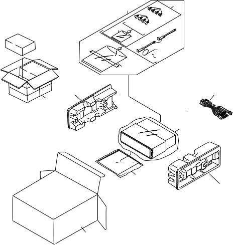
2. EXPLODED VIEWS AND PARTS LIST
2.1 PACKING
2 |
7 |
4 |
|
8
 5
5
6
10
3
 11
11
1
12
20
17
14
2
DEH-1000,10,1050
NOTE:
-Parts marked by “*” and | can not be supplied.
-Screws adjacent to mark on the product are used for disassembly.
(1)PACKING SECTION PARTS LIST
Mark No. Description |
Part No. |
|
Mark No. Description |
Part No. |
|||
|
|
|
|
|
|
|
|
|
1 |
Cord Assy |
CDE5874 |
16 |
Protector |
CHP2101 |
|
* |
2 |
Accessory Assy |
CEA2395 |
17 |
Protector |
CHP2102 |
|
|
3 |
Spring |
CBH1650 |
18 |
••••• |
|
|
|
4 |
Screw Assy |
CEA2396 |
19 |
••••• |
|
|
|
5 |
Screw |
CBA1002 |
20-1 |
Owner’s Manual |
See Contrast table(2) |
|
* |
6 |
Polyethylene Bag |
CEG-127 |
20-2 |
Owner’s Manual |
See Contrast table(2) |
|
|
7 |
Screw |
CRZ50P090FMC |
20-3 |
Installation Manual |
See Contrast table(2) |
|
|
8 |
Screw |
TRZ50P080FMC |
20-4 |
Polyethylene Bag |
CEG1116 |
|
* |
9 |
Polyethylene Bag |
CEG-158 |
* 20-5 |
Card |
See Contrast table(2) |
|
|
10 |
Handle |
CNC5395 |
|
|
|
|
|
11 |
Bush |
CNV3930 |
|
|
|
|
|
12 |
Polyethylene Bag |
See Contrast table(2) |
|
|
|
|
|
13 |
••••• |
|
|
|
|
|
|
14 |
Carton |
See Contrast table(2) |
|
|
|
|
|
15 |
Contain Box |
See Contrast table(2) |
|
|
|
|
(2) CONTRAST TABLE
DEH-1000/X1N/UC, DEH-10/X1N/UC and DEH-1050/X1N/ES are constructed the same except for the fol-
lowing:
Mark No. Symbol and Description |
|
Part No. |
|
|
DEH-1000/X1N/UC |
DEH-10/X1N/UC |
DEH-1050/X1N/ES |
||
12 |
Polyethylene Bag |
CEG1173 |
CEG1173 |
CEG-162 |
14 |
Carton |
CHG3664 |
CHG3663 |
CHG3665 |
15 |
Contain Box |
CHL3664 |
CHL3663 |
CHL3665 |
20-1 |
Owner’s Manual |
CRD2858 |
CRD2858 |
CRD2860 |
20-2 |
Owner’s Manual |
Not used |
Not used |
CRD2861 |
20-3 |
Installation Manual |
CRD2859 |
CRD2859 |
CRD2862 |
* 20-5 |
Card |
ARY1048 |
ARY1048 |
Not used |
- Owner’s Manual
Model |
Part No. |
Language |
DEH-1000/X1N/UC, DEH-10/X1N/UC |
CRD2858 |
English, French, Spanish |
DEH-1050/X1N/ES |
CRD2860 |
English, Spanish, Portuguese |
|
CRD2861 |
Arabic, Chinese |
- Installation Manual
Model |
Part No. |
Language |
DEH-1000/X1N/UC, DEH-10/X1N/UC |
CRD2859 |
English, French, Spanish |
DEH-1050/X1N/ES |
CRD2862 |
English, Spanish, Portuguese, Arabic, Chinese |
3
DEH-1000,10,1050
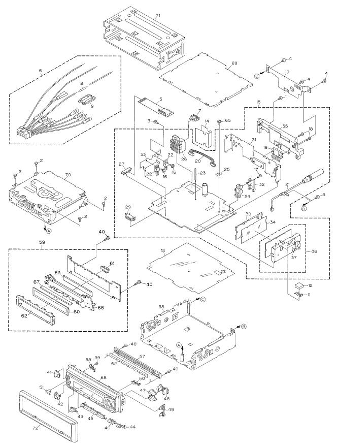
2.2 EXTERIOR
- DEH-1000/X1N/UC
4
DEH-1000,10,1050
- EXTERIOR SECTION PARTS LIST
Mark No. Description |
Part No. |
Mark No. |
Description |
Part No. |
|||
|
|
|
|
|
|
|
|
|
1 |
Screw |
BMZ26P120FMC |
36 |
FM/AM Tuner Unit |
CWE1501 |
|
|
2 |
Screw |
BSZ26P060FMC |
37 |
Holder |
CNC7532 |
|
|
3 |
Screw |
BSZ30P060FMC |
38 |
Chassis Unit |
CXB3167 |
|
|
4 |
Screw |
BSZ30P120FMC |
39 |
Screw |
BPZ20P060FMC |
|
|
5 |
Cable |
CDE6018 |
40 |
Screw |
BPZ20P080FMC |
|
|
6 |
Cord Assy |
CDE5874 |
41 |
Button(+) |
CAC5834 |
|
|
7 |
Fuse(10A) |
CEK1136 |
42 |
Button(-) |
CAC5837 |
|
|
8 |
Resistor |
RS1/2PMF102J |
43 |
Button(SOURCE) |
CAC5983 |
|
|
9 |
Cap |
CNS1472 |
44 |
Button(BAND) |
CAC5984 |
|
|
10 |
Cover |
CNC8367 |
45 |
Button(1-6) |
CAC5840 |
|
|
11 |
Earth Plate |
CNC8368 |
46 |
Button(PGM,CL) |
CAC5841 |
|
|
12 |
Spacer |
CNM4913 |
47 |
Button(UP,DOWN) |
CAC5846 |
|
|
13 |
Insulator |
CNM6006 |
48 |
Button(<>) |
CAC5849 |
|
|
14 |
Insulator |
CNM6224 |
49 |
Button(F,A) |
CAC5852 |
|
| |
15 |
Tuner Amp Unit |
CWM6092 |
50 |
Button(EJECT) |
CAC5853 |
|
|
16 |
Screw |
ASZ26P080FMC |
51 |
Button(EQ) |
CAC6132 |
|
|
17 |
Screw |
BPZ26P080FMC |
52 |
Cover |
CNM4704 |
|
|
18 |
Screw |
BSZ26P160FMC |
53 |
••••• |
|
|
|
19 |
IC(IC551) |
PAL005A |
54 |
••••• |
|
|
|
20 |
Connector(CN551) |
CDE5996 |
55 |
••••• |
|
|
|
21 |
Antenna Cable(CN502) |
CDH1254 |
56 |
••••• |
|
|
|
22 |
Transistor(Q981,991) |
2SD2396 |
57 |
Holder |
CNV5574 |
|
|
23 |
Clamper |
CEF1006 |
58 |
Housing |
CNV5575 |
|
|
24 |
Pin Jack(CN431) |
CKB1028 |
59 |
Keyboard Unit |
CWM6098 |
|
|
25 |
Terminal(CN501) |
CKF1059 |
60 |
LCD(LCD1801) |
CAW1500 |
|
|
26 |
Connector(CN951) |
CKM1299 |
61 |
Connector(CN1801) |
CKS3580 |
|
* |
27 |
Connector(CN681) |
CKS2227 |
62 |
Holder |
CNC8036 |
|
|
28 |
••••• |
|
63 |
Sheet |
CNM6026 |
|
|
29 |
Connector(CN651) |
CKS3581 |
64 |
••••• |
|
|
|
30 |
Holder |
CNC7533 |
65 |
Screw |
ISS26P055FUC |
|
|
31 |
Holder |
CNC8130 |
66 |
Lighting Conductor |
CNV5570 |
|
|
32 |
Holder |
CNC8041 |
67 |
Connector |
CNV5571 |
|
|
33 |
Holder |
CNC8043 |
68 |
Grille Unit |
CXB3504 |
|
|
34 |
Insulator |
CNM5967 |
69 |
Case Unit |
CXB4033 |
|
|
35 |
Heat Sink |
CNR1506 |
70 |
CD Mechanism Module |
CXK5200 |
|
|
|
|
|
71 |
Holder |
CNC6798 |
|
|
|
|
|
72 |
Panel |
CNS5132 |
|
5

DEH-1000,10,1050
- DEH-10/X1N/UC
6
DEH-1000,10,1050
- EXTERIOR SECTION PARTS LIST
Mark No. Description |
Part No. |
Mark No. |
Description |
Part No. |
|||
|
|
|
|
|
|
|
|
|
1 |
Screw |
BMZ26P120FMC |
36 |
FM/AM Tuner Unit |
CWE1501 |
|
|
2 |
Screw |
BSZ26P060FMC |
37 |
Holder |
CNC7532 |
|
|
3 |
Screw |
BSZ30P060FMC |
38 |
Chassis Unit |
CXB3167 |
|
|
4 |
Screw |
BSZ30P120FMC |
39 |
Screw |
BPZ20P060FMC |
|
|
5 |
Cable |
CDE6018 |
40 |
Screw |
BPZ20P080FMC |
|
|
6 |
Cord Assy |
CDE5874 |
41 |
Button(+) |
CAC5834 |
|
|
7 |
Fuse(10A) |
CEK1136 |
42 |
Button(-) |
CAC5837 |
|
|
8 |
Resistor |
RS1/2PMF102J |
43 |
Button(SOURCE) |
CAC5983 |
|
|
9 |
Cap |
CNS1472 |
44 |
Button(BAND) |
CAC5984 |
|
|
10 |
Cover |
CNC8367 |
45 |
Button(1-6) |
CAC5840 |
|
|
11 |
Earth Plate |
CNC8368 |
46 |
Button(PGM,CL) |
CAC5841 |
|
|
12 |
Spacer |
CNM4913 |
47 |
Button(UP,DOWN) |
CAC5846 |
|
|
13 |
Insulator |
CNM6006 |
48 |
Button(<>) |
CAC5849 |
|
|
14 |
Insulator |
CNM6224 |
49 |
Button(F,A) |
CAC5852 |
|
| |
15 |
Tuner Amp Unit |
CWM6092 |
50 |
Button(EJECT) |
CAC5853 |
|
|
16 |
Screw |
ASZ26P080FMC |
51 |
Button(EQ) |
CAC6132 |
|
|
17 |
Screw |
BPZ26P080FMC |
52 |
Cover |
CNM4704 |
|
|
18 |
Screw |
BSZ26P160FMC |
53 |
••••• |
|
|
|
19 |
IC(IC551) |
PAL005A |
54 |
••••• |
|
|
|
20 |
Connector(CN551) |
CDE5996 |
55 |
••••• |
|
|
|
21 |
Antenna Cable(CN502) |
CDH1254 |
56 |
••••• |
|
|
|
22 |
Transistor(Q981,991) |
2SD2396 |
57 |
Holder |
CNV5574 |
|
|
23 |
Clamper |
CEF1006 |
58 |
Housing |
CNV5575 |
|
|
24 |
Pin Jack(CN431) |
CKB1028 |
59 |
Keyboard Unit |
CWM6095 |
|
|
25 |
Terminal(CN501) |
CKF1059 |
60 |
LCD(LCD1801) |
CAW1500 |
|
|
26 |
Connector(CN951) |
CKM1299 |
61 |
Connector(CN1801) |
CKS3580 |
|
* |
27 |
Connector(CN681) |
CKS2227 |
62 |
Holder |
CNC8036 |
|
|
28 |
••••• |
|
63 |
Sheet |
CNM6026 |
|
|
29 |
Connector(CN651) |
CKS3581 |
64 |
••••• |
|
|
|
30 |
Holder |
CNC7533 |
65 |
Screw |
ISS26P055FUC |
|
|
31 |
Holder |
CNC8130 |
66 |
Lighting Conductor |
CNV5570 |
|
|
32 |
Holder |
CNC8041 |
67 |
Connector |
CNV5571 |
|
|
33 |
Holder |
CNC8043 |
68 |
Grille Unit |
CXB3503 |
|
|
34 |
Insulator |
CNM5967 |
69 |
Case Unit |
CXB4033 |
|
|
35 |
Heat Sink |
CNR1506 |
70 |
CD Mechanism Module |
CXK5200 |
|
|
|
|
|
71 |
Holder |
CNC6798 |
|
|
|
|
|
72 |
Panel |
CNS5132 |
|
7

DEH-1000,10,1050
- DEH-1050/X1N/ES
8
DEH-1000,10,1050
- EXTERIOR SECTION PARTS LIST
Mark No. Description |
Part No. |
Mark No. |
Description |
Part No. |
|||
|
|
|
|
|
|
|
|
|
1 |
Screw |
BMZ26P120FMC |
36 |
FM/AM Tuner Unit |
CWE1501 |
|
|
2 |
Screw |
BSZ26P060FMC |
37 |
Holder |
CNC7532 |
|
|
3 |
Screw |
BSZ30P060FMC |
38 |
Chassis Unit |
CXB3167 |
|
|
4 |
Screw |
BSZ30P120FMC |
39 |
Screw |
BPZ20P060FMC |
|
|
5 |
Cable |
CDE6018 |
40 |
Screw |
BPZ20P080FMC |
|
|
6 |
Cord Assy |
CDE5874 |
41 |
Button(+) |
CAC5834 |
|
|
7 |
Fuse(10A) |
CEK1136 |
42 |
Button(-) |
CAC5837 |
|
|
8 |
Resistor |
RS1/2PMF102J |
43 |
Button(SOURCE) |
CAC5983 |
|
|
9 |
Cap |
CNS1472 |
44 |
Button(BAND) |
CAC5984 |
|
|
10 |
Cover |
CNC8367 |
45 |
Button(1-6) |
CAC5840 |
|
|
11 |
Earth Plate |
CNC8368 |
46 |
Button(PGM,CL) |
CAC5841 |
|
|
12 |
Spacer |
CNM4913 |
47 |
Button(UP,DOWN) |
CAC5846 |
|
|
13 |
Insulator |
CNM6006 |
48 |
Button(<>) |
CAC5849 |
|
|
14 |
Insulator |
CNM6224 |
49 |
Button(F,A) |
CAC5852 |
|
| |
15 |
Tuner Amp Unit |
CWM6093 |
50 |
Button(EJECT) |
CAC5853 |
|
|
16 |
Screw |
ASZ26P080FMC |
51 |
Button(EQ) |
CAC6132 |
|
|
17 |
Screw |
BPZ26P080FMC |
52 |
Cover |
CNM4704 |
|
|
18 |
Screw |
BSZ26P160FMC |
53 |
••••• |
|
|
|
19 |
IC(IC551) |
PAL005A |
54 |
••••• |
|
|
|
20 |
Connector(CN551) |
CDE5996 |
55 |
••••• |
|
|
|
21 |
Antenna Cable(CN502) |
CDH1254 |
56 |
••••• |
|
|
|
22 |
Transistor(Q981,991) |
2SD2396 |
57 |
Holder |
CNV5574 |
|
|
23 |
Clamper |
CEF1006 |
58 |
Housing |
CNV5575 |
|
|
24 |
Pin Jack(CN431) |
CKB1028 |
59 |
Keyboard Unit |
CWM6098 |
|
|
25 |
Terminal(CN501) |
CKF1059 |
60 |
LCD(LCD1801) |
CAW1500 |
|
|
26 |
Connector(CN951) |
CKM1299 |
61 |
Connector(CN1801) |
CKS3580 |
|
* |
27 |
Connector(CN681) |
CKS2227 |
62 |
Holder |
CNC8036 |
|
|
28 |
••••• |
|
63 |
Sheet |
CNM6026 |
|
|
29 |
Connector(CN651) |
CKS3581 |
64 |
••••• |
|
|
|
30 |
Holder |
CNC7533 |
65 |
Screw |
ISS26P055FUC |
|
|
31 |
Holder |
CNC8130 |
66 |
Lighting Conductor |
CNV5570 |
|
|
32 |
Holder |
CNC8041 |
67 |
Connector |
CNV5571 |
|
|
33 |
Holder |
CNC8043 |
68 |
Grille Unit |
CXB3505 |
|
|
34 |
Insulator |
CNM5967 |
69 |
Case Unit |
CXB4033 |
|
|
35 |
Heat Sink |
CNR1506 |
70 |
CD Mechanism Module |
CXK5200 |
|
|
|
|
|
71 |
Holder |
CNC6798 |
|
|
|
|
|
72 |
Panel |
CNS5132 |
|
9
DEH-1000,10,1050
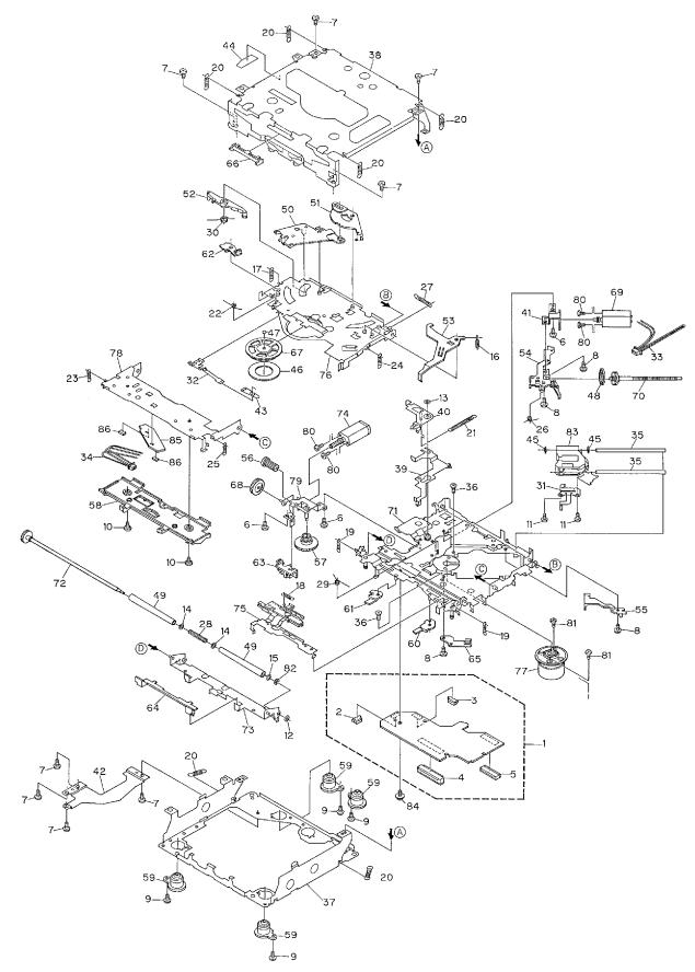
2.3 CD MECHANISM MODULE
10
DEH-1000,10,1050
- CD MECHANISM MODULE SECTION PARTS LIST
Mark No. Description |
Part No. |
Mark No. Description |
Part No. |
|||
1 |
Control Unit |
CWX2344 |
|
46 |
Sheet |
CNM6215 |
2 |
Connector(CN802) |
CKS2192 |
47 |
Ball |
CNR1189 |
|
3 |
Connector(CN801) |
CKS2193 |
48 |
Belt |
CNT1086 |
|
4 |
Connector(CN701) |
CKS2773 |
49 |
Roller |
CNV4509 |
|
5 |
Connector(CN101) |
CKS3486 |
50 |
Arm |
CNV5246 |
|
6 |
Screw |
BMZ20P030FZK |
51 |
Arm |
CNV5247 |
|
7 |
Screw |
BSZ20P040FZK |
52 |
Arm |
CNV5248 |
|
8 |
Screw(M2×3) |
CBA1077 |
53 |
Arm |
CNV5249 |
|
9 |
Screw(M2×6) |
CBA1230 |
54 |
Guide |
CNV5254 |
|
10 |
Screw |
CBA1243 |
55 |
Guide |
CNV5255 |
|
11 |
Screw(M2×4) |
CBA1362 |
56 |
Gear |
CNV5257 |
|
12 |
Washer |
CBF1037 |
57 |
Gear |
CNV5256 |
|
13 |
Washer |
CBF1038 |
58 |
Guide |
CNV5259 |
|
14 |
Washer |
CBF1060 |
59 |
Damper |
CNV5266 |
|
* 15 |
Washer |
CBF1075 |
60 |
Arm |
CNV5359 |
|
16 |
Spring |
CBH2079 |
61 |
Arm |
CNV5360 |
|
17 |
Spring |
CBH2117 |
62 |
Arm |
CNV5361 |
|
18 |
Spring |
CBH2082 |
63 |
Guide |
CNV5509 |
|
19 |
Spring |
CBH2110 |
64 |
Guide |
CNV5510 |
|
20 |
Spring |
CBH2111 |
65 |
Holder |
CNV5578 |
|
21 |
Spring |
CBH2114 |
66 |
Guide |
CNV5751 |
|
22 |
Spring |
CBH2115 |
67 |
Clamper |
CNV5758 |
|
23 |
Spring |
CBH2080 |
68 |
Gear |
CNV5813 |
|
24 |
Spring |
CBH2118 |
69 |
Motor Unit(M1) |
CXB2190 |
|
25 |
Spring |
CBH2161 |
70 |
Screw Unit |
CXB2191 |
|
26 |
Spring |
CBH2163 |
71 |
Chassis Unit |
CXB2192 |
|
27 |
Spring |
CBH2189 |
72 |
Gear Unit |
CXB2193 |
|
28 |
Spring |
CBH2249 |
73 |
Arm Unit |
CXB2194 |
|
29 |
Spring |
CBH2260 |
74 |
Motor Unit(M2) |
CXB2195 |
|
30 |
Spring |
CBH2262 |
75 |
Lever Unit |
CXB2553 |
|
31 |
Spring |
CBL1367 |
76 |
Arm Unit |
CXB2554 |
|
32 |
Spring |
CBL1369 |
77 |
Motor Unit(M3) |
CXB2562 |
|
33 |
Connector |
CDE5531 |
78 |
Arm Unit |
CXB2795 |
|
34 |
Connector |
CDE5532 |
79 |
Bracket Unit |
CXB4071 |
|
35 |
Shaft |
CLA3304 |
80 |
Screw |
JFZ20P025FMC |
|
36 |
Screw(M2.6×6) |
CBA1458 |
81 |
Screw |
JGZ17P025FZK |
|
37 |
Frame |
CNC7544 |
82 |
Washer |
YE15FUC |
|
38 |
Frame |
CNC7545 |
83 |
Pickup Unit(Service)(P8) |
CXX1285 |
|
39 |
Lever |
CNC7546 |
84 |
Screw |
IMS26P030FMC |
|
40 |
Arm |
CNC7739 |
|
* 85 PCB |
CNX2982 |
|
41 |
Bracket |
CNC7798 |
86 |
Photo-transistor(Q1, 2) |
CPT230SX-TU |
|
42 |
Plate |
CNC8090 |
|
|
|
|
43 |
Spacer |
CNM3315 |
|
|
|
|
44 |
Sheet |
CNM6170 |
|
|
|
|
45 |
Cushion |
CNM6204 |
|
|
|
|
11
|
1 |
|
2 |
|
3 |
|
4 |
|
|
|
|
|
|
DEH-1000,10,1050
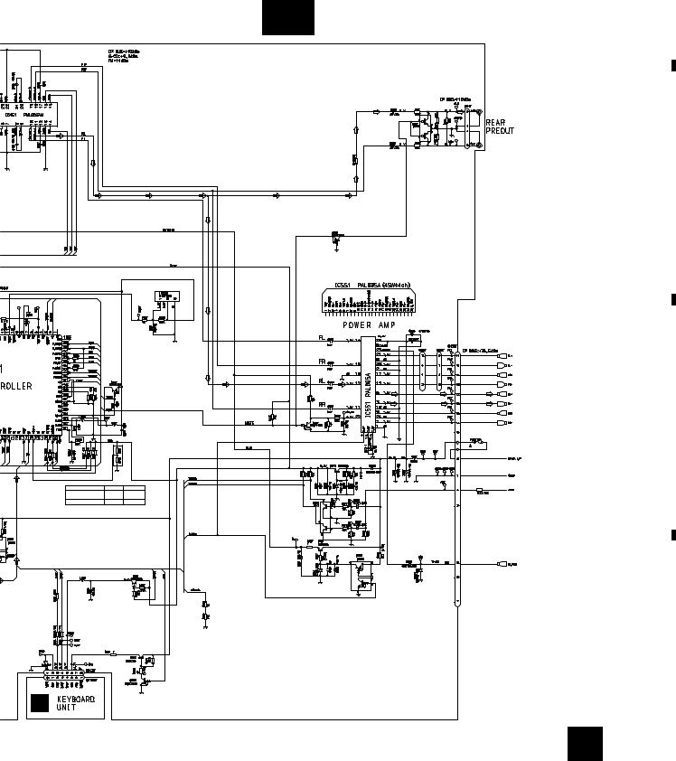
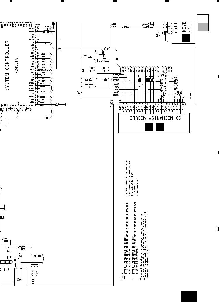
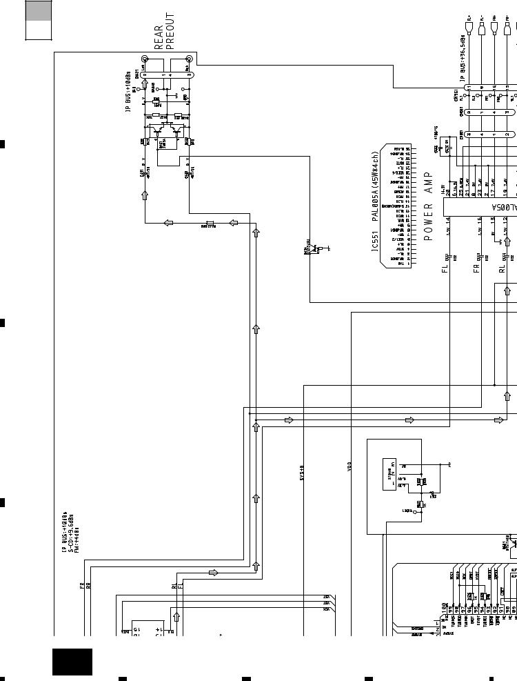
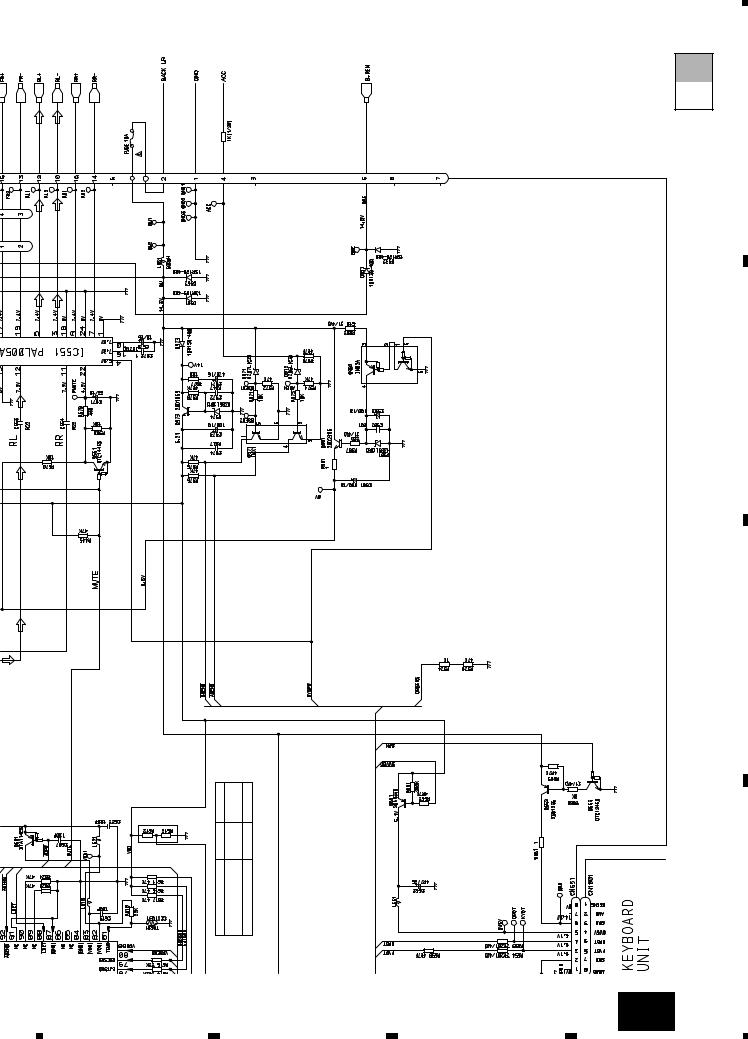
3. SCHEMATIC DIAGRAM
3.1 OVERALL CONNECTION DIAGRAM(GUIDE PAGE)
A
Note: When ordering service parts, be sure to refer to “EXPLODED VIEWS AND PARTS LIST” or “ELECTRICAL PARTS
LIST”.
A-a
|
|
|
Large size |
|
|
|
SCH diagram |
A-a |
|
A-b |
|
|
|
A
A
A-a |
A-b |
Guide page |
B |
|
|
A-a |
A-b |
Detailed page |
B
4.3V
4.3V
4.3V
4.3V |
|
4.3V |
|
4.3V |
S |
|
|
|
E |
4.3V |
|
C
ANTENNA CABLE
VD REGULATOR
D
D E
12 A
1 |
|
2 |
|
3 |
|
4 |
|
|
|
|
|
||||
|
|
|
|
|
5 |
|
6 |
|
7 |
|
8 |
|
|
|
|
|
|
DEH-1000,10,1050
A
A-b
4.3V
4.3V
4.3V
4.3V
OURCE SELECTOR, LECTRONIC VOLUME
B
RESET
C
CEK1136
DEH-P1000/X1N/UC |
R612 |
R613 |
DELETED |
0R0 |
|
DEH-P10/X1N/UC |
|
|
DEH-P1050/X1N/ES |
47K |
DELETED |
D
C
A 13
|
5 |
|
6 |
|
7 |
|
8 |
|
|
|
|
|
|
||||
|
|
|
|
|
1
DEH-1000,10,1050
A-b |
|
4.3 |
4.3 |
A-a |
|
A
4.3V |
4.3V |
4.3V |
B
C
D
A |
A |
14 A-a
2 |
3 |
4 |
4.3V |
4.3V |
|
SOURCE SELECTOR, |
ELECTRONIC VOLUME |
|
4.3V |
4.3V |
4.3V |
4.3V |
B
|
1 |
|
2 |
|
3 |
|
4 |
|
|
|
|
|
|
||||
|
|
|
|
|
5 |
6 |
7 |
8 |
DEH-1000,10,1050
A-a A-b
C
VD REGULATOR
E |
D |
CABLE
ANTENNA
A-a 15
A
B
C
D
|
5 |
|
6 |
|
7 |
|
8 |
|
|
|
|
|
|
||||
|
|
|
|
|
|
1 |
|
2 |
|
3 |
|
4 |
|
|
|
|
|
|
DEH-1000,10,1050
A-a A-b
A
B
C
D
4.3V |
4.3V |
4.3V |
4.3V |
16 A-b
RESET
E
1 |
2 |
3 |
4 |
|
5 |
|
6 |
|
7 |
|
8 |
|
|
|
|
DEH-1000,10,1050
A-a A-b
CEK1136
A
B
C
R613 |
0R0 |
DELETED |
R612 |
DELETED |
47K |
|
DEH-P1000/X1N/UC |
DEH-P10/X1N/UC DEH-P1050/X1N/ES |
D
A-b 17
5 |
6 |
7 |
8 |
|
1 |
|
2 |
|
3 |
|
4 |
|
|
|
|
|
|
DEH-1000,10,1050
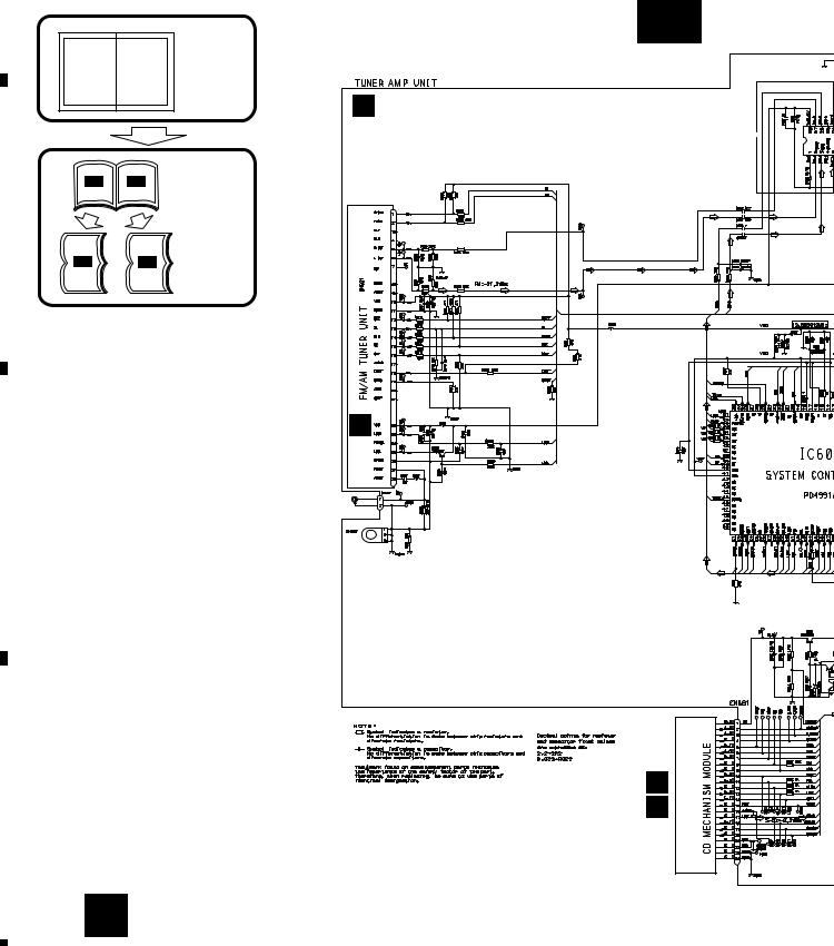
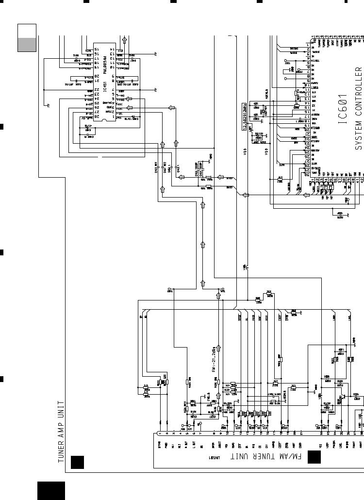
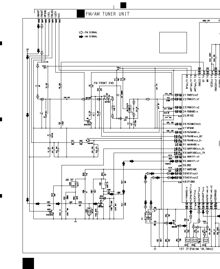
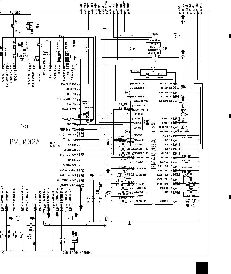
3.2 FM/AM TUNER UNIT
A  A
A
B
Voltage of IC Terminals
Mark |
Band |
Input Level |
None |
– |
– |
F0 |
FM |
0dBf |
F65 |
FM |
65dBf |
F125 |
FM |
125dBf |
A0 |
AM |
0dB |
A74 |
AM |
74dB |
A125 |
AM |
125dB |
B
KV1410(23)
C
D
18 B
|
1 |
|
2 |
|
3 |
|
4 |
|
|
|
|
|
|
||||
|
|
|
|
|
|
5 |
|
6 |
|
7 |
|
8 |
|
|
|
|
|
|
DEH-1000,10,1050
A
KV1410(23)
B
C
D
B 19
|
5 |
|
6 |
|
7 |
|
8 |
|
|
|
|
|
|
||||
|
|
|
|
|
|
1 |
|
2 |
|
3 |
|
4 |
|
|
|
|
|
|
DEH-1000,10,1050
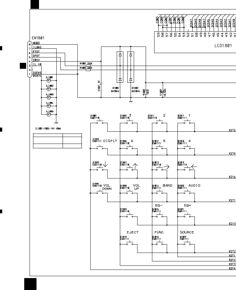
3.3 KEYBOARD UNIT
A
C KEYBOARD UNIT
A CN651
B
PGM
|
IL1801-1805 |
DEH-1000/X1N/UC |
CEL1549 |
DEH-1050/X1N/ES |
|
DEH-10/X1N/UC |
CEL1508 |
C
CLOCK
D
20 C
|
1 |
|
2 |
|
3 |
|
4 |
|
|
|
|
|
|
||||
|
|
|
|
|
|
5 |
|
6 |
|
7 |
|
8 |
|
|
|
|
|
|
DEH-1000,10,1050
A
CAW1500
B
PD6294A
C
D
C 21
|
5 |
|
6 |
|
7 |
|
8 |
|
|
|
|
|
|
||||
|
|
|
|
|

1  2
2  3
3  4
4
DEH-1000,10,1050
3.4 CD MECHANISM MODULE |
D CONTROL UNIT |
A |
|
PICKUP UNIT(SERVICE) |
|
B
C
E
PHOTO UNIT
D
22 D E
|
1 |
|
2 |
|
3 |
|
4 |
|
|
|
|
|
|
||||
|
|
|
|
|
 Loading...