


 OK / I CB
TS7
ORDER NO.
ARP3129
CANAL PLUS TUNER
TS7
BCT-1710
BCT-1720
BCT-1730
THIS MANUAL IS APPLICABLE TO THE FOLLOWING MODEL(S) AND TYPE(S).
Type |
|
|
Model |
|
Power Requirement |
Remarks |
||
TS7 |
BCT-1710 |
BCT-1720 |
BCT-1730 |
|||||
|
|
|
||||||
|
|
|
|
|
|
|
|
|
NYXK/FR |
|
– |
|
– |
– |
AC230V |
|
|
|
|
|
|
|
|
|
|
|
NYXK/SP |
– |
|
|
– |
– |
AC230V |
|
|
|
|
|
|
|
|
|
|
|
NYXK/IT |
– |
– |
|
|
– |
AC230V |
|
|
|
|
|
|
|
|
|
|
|
NYWXK/PL |
– |
– |
|
– |
|
AC230V |
|
|
|
|
|
|
|
|
|
|
|
For details, refer to "Important symbols for good services" on the next page.
PIONEER CORPORATION 4-1, Meguro 1-chome, Meguro-ku, Tokyo 153-8654, Japan
PIONEER ELECTRONICS (USA) INC. P.O. Box 1760, Long Beach, CA 90801-1760, U.S.A.
PIONEER EUROPE NV Haven 1087, Keetberglaan 1, 9120 Melsele, Belgium
PIONEER ELECTRONICS ASIACENTRE PTE. LTD. 253 Alexandra Road, #04-01, Singapore 159936
 PIONEER CORPORATION 2002
T – ZZV AUG. 2002 Printed in Japan
|
1 |
|
2 |
|
3 |
|
4 |
|
|
|
|
|
|
SAFETY INFORMATION
A
|
|
This service manual is intended for qualified service technicians; it is not meant for the casual |
|
|
do-it-yourselfer. Qualified technicians have the necessary test equipment and tools, and have been |
|
|
trained to properly and safely repair complex products such as those covered by this manual. |
|
|
Improperly performed repairs can adversely affect the safety and reliability of the product and may |
|
|
void the warranty. If you are not qualified to perform the repair of this product properly and safely, you |
|
|
|
|
|
should not risk trying to do so and refer the repair to a qualified service technician. |
|
|
WARNING |
|
|
This product contains lead in solder and certain electrical parts contain chemicals which are known to the state of California to |
B |
cause cancer, birth defects or other reproductive harm. |
|
|
|
Health & Safety Code Section 25249.6 – Proposition 65 |
NOTICE
(FOR CANADIAN MODEL ONLY)
Fuse symbols  (fast operating fuse) and/or
  (slow operating fuse) on PCB indicate that replacement parts must be of identical designation.
|
REMARQUE |
|
|
|
|
|
|
|
|
|
|
|
|
||
|
(POUR MODÈ LE CANADIEN SEULEMENT) |
|
|
|
|||||||||||
C |
Les symboles de fusible |
|
|
|
|
|
|
|
(fusible de type rapide) et/ou |
|
|
|
|
|
(fusible de type lent) sur CCI indiquent que |
les pièces de remplacement doivent avoir la même désignation. |
|
|
|
||||||||||||
|
|
|
|
||||||||||||
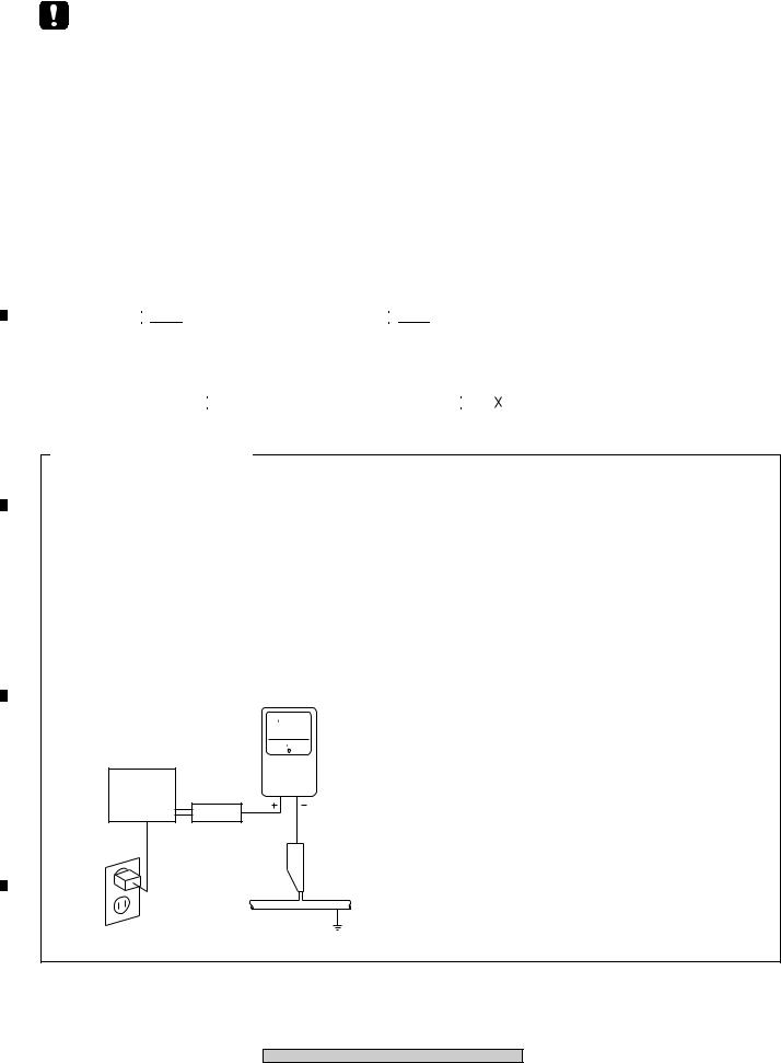
(FOR USA MODEL ONLY)
1. SAFETY PRECAUTIONS
The following check should be performed for the continued protection of the customer and service technician.
LEAKAGE CURRENT CHECK
Measure leakage current to a known earth ground (water pipe, conduit, etc.) by connecting a leakage
c u r r e n t t e s t e r s u c h a s S i m p s o n M o d e l 2 2 9 - 2 o r
D
equivalent between the earth ground and all exposed metal parts of the appliance (input/output terminals, screwheads, metal overlays, control shaft, etc.). Plug the AC line cord of the appliance directly into a 120V AC 60 Hz outlet and turn the AC power switch on. Any current measured must not exceed 0.5 mA.
|
|
|
Reading should |
|
|
Leakage |
not be above |
|
|
0.5 mA |
|
|
|
current |
|
|
|
|
|
E |
Device |
tester |
|
under |
|
|
|
|
|
|
|
|
test |
|
|
|
Test all |
|
|
|
exposed metal |
|
|
|
surfaces |
|
|
|
Also test with |
|
|
|
plug reversed |
|
|
|
(Using AC adapter |
|
Earth |
|
plug as required) |
|
ground |
AC Leakage Test
ANY MEASUREMENTS NOT WITHIN THE LIMITS OUTLINED ABOVE ARE INDICATIVE OF A POTENTIAL SHOCK HAZARD AND MUST BE CORRECTED BEFORE RETURNING THE APPLIANCE TO THE CUSTOMER.
2. PRODUCT SAFETY NOTICE
Many electrical and mechanical parts in the appliance have special safety related characteristics. These are often not evident from visual inspection nor the protection afforded by them necessarily can be obtained by using replacement components rated for voltage, wattage, etc. Replacement parts which have these special safety characteristics are identified in this Service Manual.
Electrical components having such features are identified by marking with a  on the schematics and on the parts list in this Service Manual.
The use of a substitute replacement component which does not have the same safety characteristics as the PIONEER recommended replacement one, shown in the parts list in this Service Manual, may create shock, fire, or other hazards.
Product Safety is continuously under review and new instructions are issued from time to time. For the latest information, always consult the current PIONEER Service Manual. A subscription to, or additional copies of, PIONEER Service Manual may be obtained at a nominal charge from PIONEER.
F
2
TS7, BCT-1710, BCT-1720, BCT-1730
|
1 |
|
2 |
|
3 |
|
4 |
|
|
|
|
|
|
||||
|
|
|
|
|
|
1 |
|
2 |
|
3 |
|
4 |
|
|
|
|
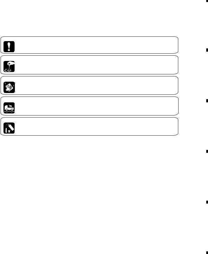
[ Important symbols for good services ]
In this manual, the symbols shown-below indicate that adjustments, settings or cleaning should be made securely. When you find the procedures bearing any of the symbols, be sure to fulfill them:
1. Product safety
You should conform to the regulations governing the product (safety, radio and noise, and other regulations), and should keep the safety during servicing by following the safety instructions described in this manual.
2. Adjustments
To keep the original performances of the product, optimum adjustments or specification confirmation is indispensable. In accordance with the procedures or instructions described in this manual, adjustments should be performed.
3. Cleaning
For optical pickups, tape-deck heads, lenses and mirrors used in projection monitors, and other parts requiring cleaning, proper cleaning should be performed to restore their performances.
4. Shipping mode and shipping screws
To protect the product from damages or failures that may be caused during transit, the shipping mode should be set or the shipping screws should be installed before shipping out in accordance with this manual, if necessary.
5. Lubricants, glues, and replacement parts
Appropriately applying grease or glue can maintain the product performances. But improper lubrication or applying
 glue may lead to failures or troubles in the product. By following the instructions in this manual, be sure to apply the
 prescribed grease or glue to proper portions by the appropriate amount.For replacement parts or tools, the prescribed ones should be used.
|
3 |
|
TS7, BCT-1710, BCT-1720, BCT-1730 |
||
|
A
B
C
D
E
F
|
1 |
|
2 |
|
3 |
|
4 |
|
|
|
|
|
|
||||
|
|
|
|
|

1  2
2  3
3  4
4
CONTENTS
|
|
|
SAFETY INFORMATION ...................................................................................................................................... |
2 |
||
A |
1. SPECIFICATIONS ............................................................................................................................................ |
5 |
||||
|
|
|
2. EXPLODED VIEWS AND PARTS LIST .......................................................................................................... |
6 |
||
|
|
|
2.1 PACKING .................................................................................................................................................... |
6 |
||
|
|
|
2.2 EXTERIOR ................................................................................................................................................. |
8 |
||
|
|
|
3. SCHEMATIC DIAGRAM ................................................................................................................................ |
10 |
||
|
|
|
3.1 BLOCKDIAGRAM |
10 |
||
|
|
|
||||
|
|
|
||||
|
|
|
3.2 OVERALL WIRING DIAGRAM ................................................................................................................ |
12 |
||
|
|
|
3.3 |
MAIN ASSY (1/8)..................................................................................................................................... |
14 |
|
|
|
|
3.4 |
MAIN ASSY (2/8)..................................................................................................................................... |
16 |
|
B |
3.5 |
MAIN ASSY (3/8)..................................................................................................................................... |
18 |
|||
3.6 |
MAIN ASSY(4/8) |
20 |
||||
|
|
|
||||
|
|
|
3.7 |
MAIN ASSY(5/8)...................................................................................................................................... |
22 |
|
|
|
|
3.8 |
MAIN ASSY(6/8)...................................................................................................................................... |
24 |
|
|
|
|
3.9 |
MAIN ASSY(7/8)...................................................................................................................................... |
26 |
|
|
|
|
3.10 MAIN ASSY(8/8).................................................................................................................................... |
28 |
||
|
|
|
3.11 FRONT ASSY |
30 |
||
|
|
|
||||
|
|
|
3.12 CARD ASSY .......................................................................................................................................... |
31 |
||
|
|
|
3.13 MODEM ASSY ...................................................................................................................................... |
32 |
||
|
|
|
3.14 POWER ASSY ...................................................................................................................................... |
34 |
||
C |
4. PCB CONNECTION DIAGRAM ..................................................................................................................... |
36 |
||||
4.1 FRONT ASSY |
36 |
|||||
|
|
|
||||
|
|
|
4.2 CARD AND MODEM ASSYS .................................................................................................................. |
37 |
||
|
|
|
4.3 MAIN ASSY ............................................................................................................................................. |
38 |
||
|
|
|
5. PCB PARTS LIST .......................................................................................................................................... |
42 |
||
|
|
|
6. ADJUSTMENT |
45 |
||
|
|
|
||||
|
|
|
............................................................................................................................7. GENERAL INFORMATION |
46 |
||
|
|
|
7.1 DIAGNOSIS ............................................................................................................................................. |
46 |
||
|
|
|
7.1.1 CHECK MODE ................................................................................................................................. |
46 |
||
|
|
|
7.1.2 TROUBLESHOOTING ..................................................................................................................... |
53 |
||
D |
7.2 |
IC ............................................................................................................................................................. |
65 |
|||
|
|
|
7.3 IC LOCATION .......................................................................................................................................... |
69 |
||
|
|
|
7.4 MOUNTING CONDITION FOR BGA ...................................................................................................... |
70 |
||
|
|
|
8. PANEL FACILITIES ....................................................................................................................................... |
74 |
||
|
|
|
|
|
|
|
|
|
|
|
|
|
|
E
F
4
TS7, BCT-1710, BCT-1720, BCT-1730
|
1 |
|
2 |
|
3 |
|
4 |
|
|
|
|
|
|
||||
|
|
|
|
|

|
1 |
|
2 |
|
3 |
|
4 |
|
|
|
|
||||
1. SPECIFICATIONS |
|
|
|
|
|||
RF |
|
|
|
|
|
|
|
Moduration Method ..................................................... |
|
QPSK |
|
|
|
|
|
Symbol Rate .................................................... |
|
18~30Mbaud |
|
|
|
|
|
Inner Code Rate .................................... |
1/2, 2/3, 3/4, 5/6,7/8 |
|
|
|
|
||
Error Correction ............................... |
|
Viterbi+Reed–solomon |
|
|
|
|
|
Frequency Range ....................................... |
|
950 to 2150MHz |
|
|
|
|
|
Input Level .................................................... |
|
–65 to –25dBm |
|
|
|
|
|
Max. Input Level ........................................................... |
|
0dBm |
|
|
|
|
|
Return Loss .......................................................... |
|
8.0dB min. |
|
|
|
|
|
Spurious Signal and |
|
|
|
|
|
|
|
|
Local Oscillator Level .................................. |
|
–63dBm max. |
|
|
|
|
LNB Power Supply ................................. |
|
Ver. : 12.5V to 14V |
|
|
|
|
|
|
|
|
Hor. : 17V to 19V |
|
|
|
|
VIDEO |
|
|
|
|
|
|
|
S/N ........................................................................ |
|
55dB min. |
|
|
|
|
|
Responce Flatness ............................ |
|
3.0dB max at 4.7MHz |
|
|
|
|
|
Differential Gain .................................................... |
|
10% max. |
|
|
|
|
|
Differential Phase ................................................. |
|
5deg max. |
|
|
|
|
|
Chroma Delay ................................................. |
|
±40nsec max. |
|
|
|
|
|
Non Linearity ........................................................... |
|
5% max. |
|
|
|
|
|
AUDIO |
|
|
|
|
|
|
|
S/N ........................................................................ |
|
72dB min. |
|
|
|
|
|
Responce flatness ........................ |
|
±1.0dB at 20Hz to 20kHz |
|
|
|
|
|
Channel Separation .............................................. |
|
60dB min. |
|
|
|
|
|
DATA COMMUNICATION |
|
|
|
|
|
|
|
Serial Interface ....................................................... |
|
RS-232C |
|
|
|
|
|
Modem(for TS7) .............................................................. |
|
V23 |
|
|
|
|
|
Modem(Except TS7) ...................................... |
|
V22 bis + V42 |
|
|
|
|
|
IC Card ................................................................... |
|
ISO-7816 |
|
|
|
|
|
GENERAL |
|
|
|
|
|
|
|
Power Requirement ....................................... |
|
AC230V/50Hz |
|
|
|
|
|
Power Consumption ................................................ |
|
18W typ. |
|
|
|
|
|
Dimensions ............................... |
380 (W) X 253 (D) X 71 (H) |
|
|
|
|
||
Net Weight ................................................................... |
|
2.0kg |
|
|
|
|
|
|
5 |
|
TS7, BCT-1710, BCT-1720, BCT-1730 |
||
|
A
B
C
D
E
F
|
1 |
|
2 |
|
3 |
|
4 |
|
|
|
|
|
|
||||
|
|
|
|
|
1  2
2  3
3  4
4
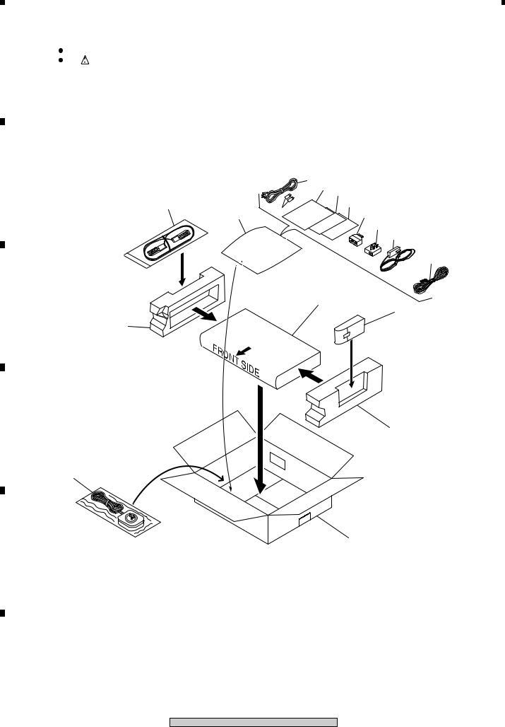
2. EXPLODED VIEWS AND PARTS LIST
NOTES: |
Parts marked by "NSP" are generally unavailable because they are not in our Master Spare Parts List. |
|
A |
The |
mark found on some component parts indicates the importance of the safety factor of the part. |
Therefore, when replacing, be sure to use parts of identical designation.  Screws adjacent to
  mark on product are used for disassembly.
 For the applying amount of lubricants or glue, follow the instructions in this manual. (In the case of no amount instructions, apply as you think it appropriate.)
2.1 PACKING
B |
|
12 |
|
|
7,8 9(Except BCT-1730) |
||
|
|
||
11 |
|
10(BCT-1730 only) |
|
6 |
14(for BCT-1710) |
||
15 |
14(for BCT-1730) 13(for TS7)
13(for BCT-1710 and BCT-1730)
4
C
5
2
D |
3 |
13 (BCT-1720 only)
1
E
F
6 |
TS7, BCT-1710, BCT-1720, BCT-1730 |
|
|
1 |
|
2 |
|
3 |
|
4 |
|
|
|
|
|
|
||||
|
|
|
|
|

1  2
2  3
3  4
4
(1) PACKING PARTS LIST
Mark |
No. |
Description |
|
Part No. |
|
|
|
1 |
Packing Case |
|
See Contrast Table(2) |
A |
|
|
2 |
Side Pad L |
|
BHA1146 |
|
|
|
3 |
Side Pad R |
|
BHA1147 |
|
|
|
4 |
Sheet |
|
AHG1153 |
|
|
|
5 |
Remote Control Unit |
|
See Contrast Table(2) |
|
|
|
6 |
Battery (R03) 2P |
|
VEM1018 |
|
|
|
7 |
Instruction Manual |
|
See Contrast Table(2) |
|
|
|
|
|||||
|
8 |
Instruction Manual (Polish) |
|
See Contrast Table(2) |
|
|
|
9 |
CE Declaration Sheet |
|
See Contrast Table(2) |
|
|
|
10 |
Caution Sheet |
|
See Contrast Table(2) |
|
|
|
11 |
Scart Cable(1m:Black) |
|
BDH1039 |
|
|
|
12 |
AC Power Cord (2m:Black) |
|
BDG1035 |
|
|
|
13 |
Modem Cable (10m:White) |
|
See Contrast Table(2) |
B |
|
NSP |
14 |
Modem Adapter |
|
See Contrast Table(2) |
||
|
|
|||||
NSP |
15 |
Catalogue Bag |
|
BHG1047 |
|
|
(2) CONTRAST TABLE
TS7/NYXK/FR, BCT-1710/NYXK/SP, BCT-1720/NYXK/IT and BCT-1730/NYWXK/PL are constructed the same
except for the following:
Mark |
No. |
Symbol and Description |
|
Part No. |
|
Remarks |
||
|
|
|
|
|||||
TS7 |
BCT-1710 |
BCT-1720 |
BCT-1730 |
|||||
|
|
|
|
|||||
|
|
|
/NYXK/FR |
/NYXK/SP |
/NYXK/IT |
/NYWXK/PL |
|
|
|
|
|
|
|
|
|
|
|
|
1 |
Packing Case |
BHD1369 |
BHD1533 |
BHD1534 |
BHD1535 |
|
|
|
5 |
Remote Control Unit |
BXD1010 |
BXD1016 |
BXD1018 |
BXD1037 |
|
|
|
7 |
Instruction Manual |
BRC1054 |
BRC1055 |
BRC1056 |
BRC1057 |
|
|
|
|
|
(French) |
(Spanish) |
(Italian) |
(Polish) |
|
|
|
8 |
Instruction Manual (Polish) |
Not used |
Not used |
Not used |
BRC1069 |
|
|
NSP |
9 |
CE Declaration Sheet |
BRM1057 |
BRM1058 |
BRM1059 |
Not used |
|
|
NSP |
10 |
Caution Sheet |
Not used |
Not used |
Not used |
BRM1061 |
|
|
|
13 |
Modem Cable |
BDH1040 |
BDH1037 |
BDH1028 |
BDH1037 |
|
|
|
14 |
Modem Adapter |
Not used |
BKP1124 |
Not used |
BKP1130 |
|
|
|
|
|
|
|
|
|
|
|
|
7 |
|
TS7, BCT-1710, BCT-1720, BCT-1730 |
||
|
C
D
E
F
|
1 |
|
2 |
|
3 |
|
4 |
|
|
|
|
|
|
||||
|
|
|
|
|
1
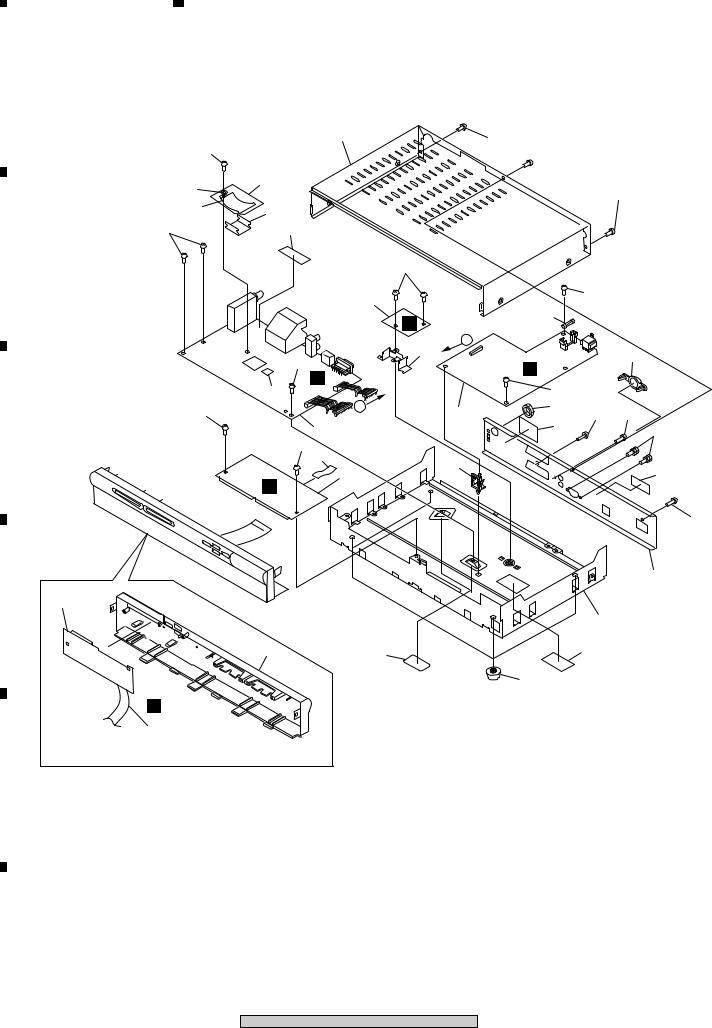
2.2 EXTERIOR
A
24
23
22
24
B
24
C
D 2
B
7
E
F
8
2 |
|
3 |
|
4 |
|
|
|
|
12 |
27 |
 27
27
21
|
|
27 |
|
20 |
|
|
|
30 |
|
|
|
24 |
|
|
|
4 |
24 |
|
|
|
|
||
D |
6 |
|
|
|
|
||
14 |
A |
|
|
|
29 |
||
24 |
E |
||
|
|||
A |
|
||
24 |
|
||
31 |
|
||
A |
25 |
28 |
|
5 |
28 |
||
1 |
16 |
26 |
|
|
|
||
24 |
|
|
|
8 |
|
|
|
15 |
|
17 |
|
3 |
|
C
28
11
10
9 |
18 |
19 |
|
|
|
|
|
13 |
TS7, BCT-1710, BCT-1720, BCT-1730
|
1 |
|
2 |
|
3 |
|
4 |
|
|
|
|
|
|
||||
|
|
|
|
|

1  2
2  3
3  4
4
(1) EXTERIOR PARTS LIST
Mark |
No. |
Description |
|
|
Part No. |
|
|
|
1 |
MAIN ASSY |
See Contrast Table (2) |
||||
|
2 |
FRONT ASSY |
BWX1216 |
|
|
||
|
3 |
CARD ASSY |
BWE1132 |
|
|
||
|
4 |
MODEM ASSY |
BWX1215 |
|
|
||
|
5 |
POWER ASSY |
BXF1166 |
|
|
||
|
6 |
Fuse (1102: T2.5AH250V) |
REK1102 |
|
|
||
|
7 |
19P FFC(J2) |
BDD1057 |
|
|
||
|
|
(MAIN CN7002-FRONT CN8001) |
|
|
|
||
|
8 |
12P FFC(J1) |
BDD1033 |
|
|
||
|
|
(MAIN CN2501-CARD CN8503) |
|
|
|
||
|
9 |
Front Panel Assy |
See Contrast Table (2) |
||||
|
10 |
Chassis |
BNA1161 |
|
|
||
|
11 |
Rear Panel Assy |
BWX1221 |
|
|
||
|
12 |
Bonnet Case |
BNE1136 |
|
|
||
|
13 |
Foot |
AEC-672 |
|
|
||
|
14 |
PCB Holder |
BNG1341 |
|
|
||
|
15 |
Card Edge Spacer |
BEC1246 |
|
|
||
NSP |
16 |
Name Label |
See Contrast |
Table (2) |
|||
NSP |
17 |
Caution Label |
BAL1446 |
|
|
||
|
18 |
Protect Label |
BAX1302 |
|
|
||
NSP |
19 |
Modem Label |
See Contrast |
Table (2) |
|||
|
20 |
Heat Sink |
BNH1061 |
|
|
||
|
21 |
Heat Sink Assy |
BNH1062 |
|
|
||
NSP |
22 |
Heat Sink |
BNH1060 |
|
|
||
NSP |
23 |
Washer |
ABE-053 |
|
|
||
|
24 |
Screw |
ABA1011 |
|
|
||
|
25 |
Washer Faced Nut |
BBN1005 |
|
|
||
|
26 |
Hexagon Headed screw |
BBA1059 |
|
|
||
|
27 |
Screw |
BBA1062 |
|
|
||
|
28 |
Screw |
BBZ30P080FZK |
||||
|
29 |
Screw Cover |
BMR1158 |
|
|
||
|
30 |
Serial No. Label |
See Contrast |
Table (2) |
|||
|
31 |
FLASH Memory IC (IC3001) |
See Contrast |
Table (2) |
|||
A
B
C
(2) CONTRAST TABLE
D
TS7/NYXK/FR, BCT-1710/NYXK/SP, BCT-1720/NYXK/IT and BCT-1730/NYWXK/PL are constructed the same
except for the following:
Mark |
No. |
Symbol and Description |
|
Part No. |
|
Remarks |
|
|
|
|
|
|
|
|
|
||||||
TS7 |
BCT-1710 |
BCT-1720 |
BCT-1730 |
|
|
|
||||
|
|
|
|
|
||||||
|
|
|
/NYXK/FR |
/NYXK/SP |
/NYXK/IT |
/NYWXK/PL |
|
|
|
|
|
|
|
|
|||||||
|
|
|
|
|
|
|
|
|
||
|
1 |
MAIN ASSY |
BWE1129 |
BWE1130 |
BWE1131 |
BWE1143 |
|
|
|
|
|
9 |
Front Panel Assy |
BWX1217 |
BWX1218 |
BWX1219 |
BWX1220 |
|
|
||
NSP |
16 |
Name Label |
BAL1449 |
BAL1453 |
BAL1454 |
BAL1455 |
|
|
||
NSP |
17 |
Caution Label |
BAL1466 |
BAL1467 |
BAL1468 |
BAL1469 |
|
|
||
NSP |
19 |
Modem Label |
Not used |
Not used |
Not used |
BAL1456 |
|
E |
||
|
|
|
|
|
|
|
|
|||
NSP |
30 |
Serial No. Label |
BAX1145 |
BAX1181 |
BAX1189 |
BAX1250 |
|
|
||
|
31 |
FLASH Memory IC (IC3001) |
BGC1079-A-RD |
BGC1080-A-RD |
BGC1081-A-RD |
BGC1082-A-RD |
|
|
||
|
|
|
|
|
|
|
|
|
|
|
|
|
|
|
|
|
|
|
|
|
|
|
|
|
|
|
|
|
|
|
|
|
F
|
9 |
|
TS7, BCT-1710, BCT-1720, BCT-1730 |
||
|
|
1 |
|
2 |
|
3 |
|
4 |
|
|
|
|
|
|
||||
|
|
|
|
|
|
1 |
|
2 |
|
3 |
|
4 |
|
|
|
|
|
|
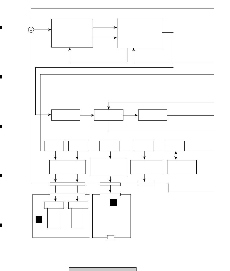
3. BLOCKDIAGRAM AND SCHEMATIC DIAGRAM
3.1 BLOCKDIAGRAM
A
Antenna |
|
|
|
|
|
|
IC1004 |
|
|
|
In |
M1001 |
|
|
|
Ich Out |
|
|
|
||
|
|
|
|
|
|
|
||||
|
DBS FRONT END |
|
|
QPSK Link IC |
TS |
|
||||
|
|
Qch Out |
|
|
||||||
|
|
|
|
|
|
|
|
|
|
|
|
BXF1167 |
|
|
|
STV0299B |
|
|
|
||
B |
|
|
|
|
|
|
|
|
|
|
|
|
|
|
|
I2C |
|
I2C |
|
|
|
|
IC2001 |
|
Programable Transport IC(OMEGA) |
|
|
|||||
|
|
STI5512AWE : TS7/BCT-1710/BCT-1720 |
|
|
|
|||||
|
|
STI5512AWE/E : BCT-1730 |
|
|
|
|
||||
C |
|
|
|
|
|
|
|
MPEG2 BUS |
||
|
|
|
|
|
|
|
|
|
|
|
|
Demux |
MPEG2 |
MPEG A/V |
Y,Cb,Cr |
PAL/SECAM |
|
||||
|
|
|
Decoder |
|
Encoder |
|
|
|||
|
|
|
|
|
|
|
|
|
||
|
|
|
|
|
|
|
|
Audio PCM |
|
|
|
CARD |
|
|
CARD |
|
UART |
|
UART |
|
PIO |
|
I/F |
|
|
I/F |
|
|
|
|||
D |
|
|
|
|
|
|
|
|
||
|
|
|
|
|
|
|
|
|
|
|
|
IC2502 |
|
|
IC6006,IC6005 |
IC5006 |
|
IC2004 |
|||
|
|
|
|
MODEM IC |
|
|||||
|
CARD Interface |
|
RS232C Driver |
|
DALLAS ID |
|||||
|
|
|
|
|||||||
|
TC74VHCT126AFT |
AMC2442ACV(0.87) |
HIN211CA |
|
90-B011X-03A |
|||||
|
|
73K324BL-IH |
|
|
||||||
|
|
|
|
|
|
|
|
|
|
|
CN2501 |
|
|
|
CN6001 |
CN5004 |
|
|
|||
|
|
|
|
|
|
|
||||
|
|
|
|
|
|
|
|
RS232C |
|
|
|
|
|
|
|
|
|
|
to Personal |
|
|
CN8503 |
|
|
|
|
CN6101 |
|
Computer |
|
|
|
E |
|
|
|
|
|
D |
|
|
|
|
|
CARD Slot |
CARD Slot |
|
|
|
|
|
|||
|
|
MODEM |
|
|
|
|
||||
|
|
|
|
|
|
|
|
|
|
|
C |
CA |
|
|
BANK |
|
ASSY |
|
|
|
|
CARD |
|
|
CARD |
|
V23 : TS7 |
|
|
|
|
|
|
|
|
|
|
|
V22bis+V42 : other |
|
|
|
|
|
|
|
|
|
|
models |
|
|
|
|
CARD ASSY |
BWE1132 |
|
BWX1215 |
|
|
|
|
|||
|
|
|
|
|
|
|||||
|
|
|
|
|
|
to Telephone Line |
|
|
|
|
F |
|
|
|
|
|
|
|
|
|
|
10
TS7, BCT-1710, BCT-1720, BCT-1730
|
1 |
|
2 |
|
3 |
|
4 |
|
|
|
|
|
|
||||
|
|
|
|
|
|
5 |
|
6 |
|
7 |
|
8 |
|
|
|
|
|
|
|
|
|
|
|
|
|
|
|
|
|
|
|
|
|
|
|
|
|
|
|
|
|
|
|
|
|
|
|
|
|
|
|
|
|
|
|
CN4002-2 |
|
|
TV |
|||||||
|
|
|
|
|
|
|
|
|
|
|
|
|
|
|
|
|
|
|
|
|
|
|
|
|
|
|
|
|
|
|
|
|
|
|
|
|
|
|
|
||||||||||
|
|
|
|
|
|
|
|
|
|
|
|
|
|
|
|
|
|
|
|
|
|
|
|
|
|
|
|
|
|
|
|
|
|
|
|
|
|
|
|
|
|
|
|
|
|
|
|
||
|
|
|
|
|
|
MAIN ASSY |
|
|
|
|
|
|
|
|
|
|
|
|
|
|
|
|
|
|
|
|
|
|
|
|
|
|
|
|
|
|
|
|
|
|
|
SCART |
|||||||
|
|
|
|
|
|
|
|
|
|
|
|
|
|
|
|
|
|
|
|
|
|
|
|
|
|
|
|
|
|
|
|
|
|
|
|
|
|
|
|
|
|||||||||
|
|
|
|
A |
|
|
|
|
|
|
|
|
|
|
|
|
|
|
|
|
|
|
|
|
|
|
|
CVBS, |
Delete |
|
|
|
|
|
|
|
|
|
|||||||||||
|
|
|
|
|
|
BWE1129 : TS7 |
|
|
|
|
|
|
|
|
|
|
|
|
|
|
|
|
|
|
|
|
|
|
|
|
|
|
|
|
|
|
|
|
|||||||||||
|
|
|
|
|
|
|
|
|
|
|
|
|
|
|
|
|
|
|
|
|
|
|
|
|
|
|
|
|
|
|
|
|
|
|
|
|
|
|
|
|
|
|
|||||||
|
|
|
|
|
|
BWE1130 : BCT-1710 |
|
|
|
|
|
|
|
|
|
|
|
|
RchLch, RGB, |
RchLch,CVBS, |
CVBS, |
CVBS, |
SCARTVCR |
||||||||||||||||||||||||||
|
|
|
|
|
|
|
|
|
|
|
|
BGC1082-A-RD : BCT-1730 |
|
|
|
|
|
|
|
||||||||||||||||||||||||||||||
|
|
|
|
|
|
BWE1131 : BCT-1720 |
|
|
|
|
|
|
|
|
|
|
|
|
|
|
|
CN4002-1 |
|
|
|||||||||||||||||||||||||
|
|
|
|
|
|
BWE1143 : BCT-1730 |
|
|
|
|
|
|
|
|
|
|
|
|
|
|
|
|
|
||||||||||||||||||||||||||
|
|
|
|
|
|
|
|
|
|
|
|
BGC1079-A-RD : TS7 |
|
|
|
|
|
|
|
|
|
|
|
|
|
|
|
|
|
|
|
|
|
||||||||||||||||
|
|
|
|
|
|
|
|
|
|
|
|
BGC1080-A-RD : BCT-1710 |
|
|
|
|
|
|
|
|
|
|
|
|
|
|
|
|
|
|
|
|
|
||||||||||||||||
|
|
|
|
|
|
|
|
|
|
|
|
|
|
|
|
|
|
|
|
|
|
|
|
|
|
|
|
|
|
|
|
|
|||||||||||||||||
|
|
|
|
|
|
|
|
|
|
|
|
BGC1081-A-RD : BCT-1720 |
|
|
|
|
|
|
|
|
|
|
|
|
|
|
|
|
|
|
|
|
|
||||||||||||||||
|
|
|
|
|
|
|
|
|
|
|
|
|
|
|
|
|
|
|
|
|
|
|
|
|
|
|
|
|
|
|
|
|
|
|
|
|
|
|
RchLch,C,Y, |
|
|
|
|
|
|
|
|
||
|
|
|
|
|
|
|
|
|
|
|
|
|
|
|
|
IC3001 |
|
|
|
|
|
|
|
|
|
|
|
|
|
|
|
RchLch, RchLch,RGB, |
|
|
JACKRCA |
||||||||||||||
|
CPU |
|
|
|
|
CPU BUS |
|
|
|
16MBit Dual |
|
|
|
|
|
|
|
|
|
|
|
|
|
|
|
|
|
|
|
|
|
|
|
|
|
|
|||||||||||||
|
|
|
|
|
|
|
|
|
|
|
|
|
|
|
|
|
|
|
|
|
|
JA4001 |
|
|
|||||||||||||||||||||||||
|
|
|
|
|
|
|
|
|
|
Bank FLASH |
|
|
|
|
|
|
|
|
|
|
|
|
|
|
|
|
|
|
|
||||||||||||||||||||
|
|
|
|
|
|
|
|
|
|
|
|
|
|
|
|
|
|
|
|
|
|
|
|
|
|
|
|
|
|
|
|
|
|
|
|
|
|
|
|
|
|
||||||||
|
|
|
|
|
|
|
|
|
|
|
|
|
|
|
|
HYB39S64160BT-8 |
|
|
|
|
|
|
|
|
|
|
|
|
|
|
|
|
|
|
|
|
|
||||||||||||
|
|
|
|
|
|
|
|
|
|
|
|
|
|
|
|
IC3002 |
|
|
|
|
|
|
|
|
|
|
|
|
|
|
|
|
|
|
|
|
|
|
|
|
|
|
|||||||
|
|
|
|
|
|
|
|
|
|
|
|
|
|
|
|
|
64MBit |
|
|
|
|
|
|
|
|
|
|
|
|
|
|
|
|
|
|
|
|
|
|
|
|
|
|
||||||
|
|
|
|
|
|
|
|
|
|
|
|
|
|
|
|
|
|
|
|
|
|
|
|
|
|
|
|
|
|
|
|
|
|
|
|
|
|
|
|
|
|
|
|||||||
|
|
|
|
|
|
|
|
|
|
|
|
|
|
|
|
|
SDRAM |
|
|
|
|
|
|
|
|
|
|
|
|
|
|
|
|
|
|
|
|
|
|
|
|
|
|
||||||
|
|
|
|
|
|
|
|
|
|
|
|
|
|
|
|
|
|
|
|
|
|
|
|
|
|
|
|
|
|
|
|
|
|
|
|
|
|
|
|
|
|
|
|||||||
|
|
|
|
|
|
|
|
|
|
|
|
CVBS, Y, C, RGB |
|
|
|
|
|
|
|
|
IC4001 |
|
|
|
|
|
|
|
|
|
|
|
|
||||||||||||||||
|
|
|
|
|
|
|
|
|
|
|
|
|
|
|
|
|
|
|
|
|
|
|
|
|
|
|
|
|
|
|
|
|
|
|
|
AV Switch |
|
|
|
|
|
||||||||
|
|
|
|
|
|
|
|
|
|
|
|
|
|
|
|
IC4004 |
|
Lch, Rch |
|
|
|
|
|
|
|
|
|
|
|
|
|
|
|
|
|
|
|
|
|
||||||||||
|
|
|
|
|
|
|
|
|
|
|
|
|
|
|
|
Audio DAC |
|
|
|
|
|
|
CXA2161R |
|
|
|
|
|
|
|
|
|
|
||||||||||||||||
|
|
|
|
|
|
|
|
|
|
|
|
|
|
|
|
|
|
|
|
|
|
|
|
|
|
|
|
|
|
|
|
|
|
|
|
||||||||||||||
|
|
|
|
|
|
|
|
|
|
|
|
|
|
|
|
CS4334-KS |
|
|
|
CN7001 |
|
|
|
|
|
|
|
|
|
|
|
|
|
|
|
|
|
|
|
|
|
||||||||
|
|
|
|
|
|
|
|
|
|
|
|
|
|
|
|
|
|
|
|
|
|
|
|
|
|
|
|
|
|
|
|
|
|
|
|
|
|||||||||||||
|
|
|
|
|
|
|
|
|
|
|
|
|
|
|
|
|
|
|
|
|
|
|
|
|
|
|
|
|
|
|
|
|
|
|
|
|
|
|
|
|
|
|
|
|
|
|
|
||
|
|
|
|
|
|
|
|
|
|
|
|
|
|
|
|
|
|
|
|
|
|
|
|
|
|
|
|
|
|
|
|
|
|
|
|
|
|
|
|
|
|
|
|
|
|
|
|
||
|
|
|
|
I2C |
|
|
|
|
|
|
|
|
|
|
|
|
|
|
|
|
|
+3.3V |
|
4-7 |
|
0203 |
|
|
|
|
|
|
|
|
|
|
|
|
|
||||||||||
|
|
|
|
|
|
|
|
|
|
|
|
|
|
|
|
|
|
|
|
|
|
|
|
|
|
|
|
+3.3V |
|
|
|
|
|
|
|
|
|
|
|
||||||||||
|
|
|
|
|
|
|
|
|
|
|
|
|
|
|
|
|
|
|
|
|
|
|
|
|
|
|
|
|
|
|
|
|
|
|
|
|
|
|
|
|
|
|
|||||||
|
|
|
|
|
|
|
|
|
|
|
|
|
|
|
|
|
|
|
|
|
|
|
|
|
|
|
|
|
|
|
|
|
|
|
|
|
|
|
|
|
|
|
|||||||
|
|
|
|
|
|
|
|
|
|
|
|
|
|
|
|
|
|
|
|
|
|
|
|
|
|
|
|
8,9 |
|
|
|
|
|
|
|
|
|
|
|
|
|
|
|
||||||
|
|
|
|
|
|
|
|
|
|
|
|
|
|
|
|
|
|
|
|
|
|
|
|
|
+5V |
|
|
|
|
|
|
|
+5V |
|
|
|
|
|
|
|
|
|
|
|
|||||
|
|
|
|
|
|
|
|
|
|
|
|
|
|
|
|
|
|
|
|
|
|
|
|
|
|
|
|
12 |
|
|
|
|
|
|
|
|
|
|
|
|
|
|
|
||||||
|
|
|
|
|
|
|
|
|
|
|
|
|
|
|
|
|
|
|
|
|
|
|
|
|
–5V |
|
|
|
|
|
|
|
–5V |
|
|
|
|
|
|
|
|
|
|
|
|||||
|
|
|
|
|
|
|
|
|
|
|
|
|
|
|
|
|
|
|
|
|
|
|
|
|
|
|
|
14 |
|
|
|
|
|
|
|
|
|
|
|
|
|
|
|
||||||
|
|
|
|
|
|
|
|
|
|
|
|
|
|
|
|
|
|
|
|
|
|
|
|
|
+12V |
|
|
|
|
|
|
|
+12V |
|
|
|
|
|
|
|
|
|
|
|
|||||
|
|
|
|
|
|
|
|
|
|
|
|
|
|
|
|
|
|
|
|
|
|
|
|
|
|
|
|
16 |
|
|
|
|
|
|
|
|
|
|
|
|
|
|
|
||||||
|
|
|
|
|
|
|
|
|
|
|
|
|
|
|
|
|
|
|
|
|
|
|
|
+24/19V |
|
|
|
|
|
|
|
+24/19V |
|
|
|
|
|
|
|
|
|
|
|
||||||
|
|
IC7002 |
|
|
IC7001 |
|
|
|
|
|
|
|
|
|
|
|
|
|
|
|
|
|
|
|
|||||||||||||||||||||||||
|
|
|
|
|
|
|
|
|
|
18 |
|
|
|
|
|
|
|
|
|
|
|
|
|
|
|
||||||||||||||||||||||||
|
|
|
|
|
|
|
|
+6V |
|
|
|
|
|
|
|
+6V |
|
|
|
|
|
|
|
|
|
|
|
||||||||||||||||||||||
|
|
16KBit EEPROM |
|
|
|
|
|
SUB CPU |
|
|
|
|
|
|
|
|
|
|
|
|
|
|
|
|
|
|
|
|
|
|
|||||||||||||||||||
|
|
|
|
|
|
|
|
|
|
|
|
|
|
19 |
|
|
|
|
|
|
|
|
|
|
|
|
|
|
|
||||||||||||||||||||
|
|
|
|
|
|
|
|
|
|
|
+28V |
|
|
|
|
|
|
|
+28V |
|
|
|
|
|
|
|
|
|
|
|
|||||||||||||||||||
|
|
CAT24WC16JI |
|
|
PE5325A |
|
|
|
|
|
|
|
|
|
|
|
|
|
|
|
|
|
|
|
|
|
|
||||||||||||||||||||||
|
|
|
|
|
|
|
|
|
|
|
13 |
|
|
|
|
|
|
|
|
|
|
|
|
|
|
|
|||||||||||||||||||||||
|
|
|
|
|
|
|
|
|
|
|
|
|
|
|
|
|
AC_PWR |
|
|
|
|
|
|
|
|
|
|
|
|||||||||||||||||||||
|
|
|
|
|
|
|
|
|
|
CN7002 |
|
|
|
|
|
|
|
|
|
|
|
|
AC_PWR |
|
|
|
|
|
|
|
|
|
|
|
|
|
|
|
|
|
|
|
|
|
|
||||
|
|
|
|
|
|
|
|
|
|
|
|
|
|
|
|
|
|
|
|
|
|
|
|
|
|
|
|
|
|
|
|
|
|
|
|
|
|
|
|
|
|
|
|
|
|
|
|||
|
|
|
|
|
|
|
|
|
|
|
|
|
|
|
|
|
|
|
|
|
|
|
|
|
|
|
|
|
|
|
|
|
|
|
|
|
|
|
|
|
|
|
|
|
|
|
|
|
|
|
|
|
|
|
|
|
|
|
|
|
|
|
|
|
|
|
|
|
|
|
|
|
|
|
|
|
|
|
|
|
|
|
|
|
|
|
|
|
|
|
|
|
|
|
|
|
|
|
|
|
|
|
> |
E |
CN8001 |
|
|
POWER ASSY |
|
|
|
|
||
KEY |
IR |
LED |
BXF1166 |
|
|
|
|
||
B FRONT ASSY |
|
|
||
BWX1216 |
|
|
|
|
A
B
C
D
E
F
|
11 |
|
TS7, BCT-1710, BCT-1720, BCT-1730 |
||
|
|
5 |
|
6 |
|
7 |
|
8 |
|
|
|
|
|
|
||||
|
|
|
|
|

|
1 |
|
2 |
|
3 |
|
4 |
|
|
|
|
|
|
3.2 OVERALL WIRING DIAGRAM
A |
|
|
|
|
B |
BXF1167- |
|
|
|
C |
|
|
|
|
|
A (A 1/8- A 8/8) MAIN ASSY |
|
|
|
|
|
(BWE1129 : TS7/NYXK/FR) |
|
|
|
|
(BWE1130 : BCT-1710/NYXK/SP) |
|
|
|
|
(BWE1131 : BCT-1720/NYXK/IT) |
|
|
|
|
(BWE1143 : BCT-1730/NYWXK/PL) |
|
|
D |
|
|
|
|
|
|
C CARD ASSY |
|
|
|
|
(BWE1132) |
|
|
E |
|
|
|
|
F |
|
|
|
|
|
12 |
TS7, BCT-1710, BCT-1720, BCT-1730 |
|
|
|
|
|
||
|
1 |
2 |
3 |
4 |
|
5 |
|
6 |
|
7 |
|
8 |
|
|
|
|
|
|
Note : When ordering service parts, be sure to refer to "EXPLODED VIEWS and PARTS LIST" or "PCB PARTS LIST"
|
A |
|
CN6102 |
|
BKP1137- |
BKM1085- |
|
|
B |
D |
MODEM ASSY |
(BWX1215) |
|
|
C |
|
E POWER ASSY |
|
(BXF1166) |
|
D |
B FRONT ASSY (BWX1216)
E
F
|
13 |
|
TS7, BCT-1710, BCT-1720, BCT-1730 |
||
|
|
5 |
|
6 |
|
7 |
|
8 |
|
|
|
|
|
|
||||
|
|
|
|
|
|
1 |
|
2 |
|
3 |
|
4 |
|
|
|
|
|
|
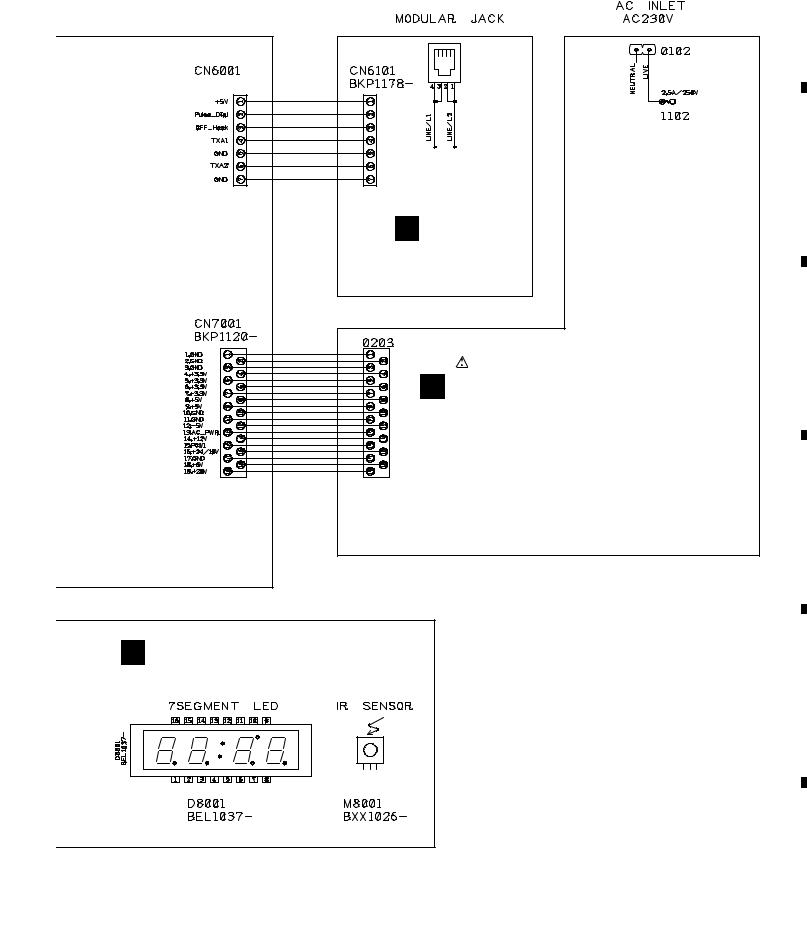
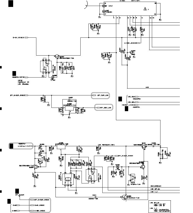
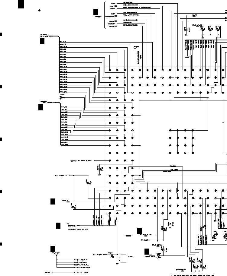
3.3 MAIN ASSY(1/8)
A A 1/8 MAIN ASSY (1/8)  CHDEC BLOCK
|
(TS7 |
: |
BWE1129) |
|
(BCT-1710 |
: |
BWE1130) |
|
(BCT-1720 |
: |
BWE1131) |
|
(BCT-1730 |
: |
BWE1143) |
|
B
A 7/8
C
D
LNB Power
A 7/8
DBS Front End
A 2/8
A 7/8
E
A 7/8
A 7/8
F
14 |
A |
1/8 |
|
TS7, BCT-1710, BCT-1720, BCT-1730 |
|
1 |
|
2 |
|
3 |
|
4 |
|
|
|
|
|
|
||||
|
|
|
|
|
5 |
6 |
7 |
|
8 |
|
|
|
|
A |
|
|
|
A 2/8 |
B |
|
|
|
|
|
|
|
|
|
C |
|
QPSK Link IC |
|
|
|
|
|
|
|
D |
|
|
|
|
E |
|
A 7/8 |
|
|
|
: The power supply is shown with the marked box.
F
|
|
A |
1/8 15 |
TS7, BCT-1710, BCT-1720, BCT-1730 |
|
5 |
|
6 |
|
7 |
|
8 |
|
|
|
|
|
|
||||
|
|
|
|
|
|
1 |
|
2 |
|
3 |
|
4 |
|
|
|
|
|
|
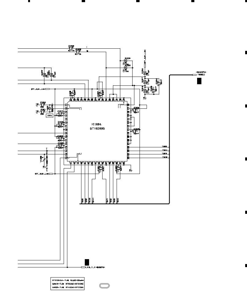
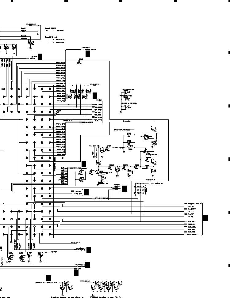
3.4 MAIN ASSY(2/8)
A |
A 2/8 MAIN ASSY (2/8) |
A 3/8 |
||
|
DMXCPU BLOCK |
|||
|
(TS7 |
: BWE1129) |
|
|
|
(BCT-1710 |
: |
BWE1130) |
|
|
(BCT-1720 |
: |
BWE1131) |
|
|
(BCT-1730 |
: |
BWE1143) |
|
|
A 3/8 |
|
|
|
B
A 3/8
C
D
A 7/8
E
A 5/8
A 7/8
F |
A |
7/8 |
|
2.2K |
IC2001 |
|
TS7/BCT-1710/BCT-1720 : STI5512AWE |
|
BCT-1730 |
: STI5512AWE/E |
Programable Transport IC(OMEGA) |
|
2.2K
A 7/8
A 7/8 |
2.2K |
|
90-B011X-03A-TLB
DALLAS ID IC
16 |
A |
2/8 |
|
TS7, BCT-1710, BCT-1720, BCT-1730 |
|
1 |
|
2 |
|
3 |
|
4 |
|
|
|
|
|
|
||||
|
|
|
|
|
5 |
6 |
7 |
8 |
|
|
|
A |
A 1/8 |
A 3/8 |
|
|
|
|
|
|
|
|
|
B |
|
A 3/8 |
|
|
E |
|
|
C |
|
|
|
|
) |
|
|
|
|
A 6/8 |
|
|
|
|
A 7/8 |
D |
|
A 1/8,4/8,7/8 |
|
|
|
|
|
|
|
|
|
A 8/8 |
|
|
|
E |
|
A 4/8 |
|
|
|
A 4/8 |
|
|
A 7/8 |
A 7/8 |
|
|
|
|
|
|
|
|
|
F |
|
|
A |
2/8 17 |
TS7, BCT-1710, BCT-1720, BCT-1730 |
|
5 |
|
6 |
|
7 |
|
8 |
|
|
|
|
|
|
||||
|
|
|
|
|
|
1 |
|
2 |
|
3 |
|
4 |
|
|
|
|
|
|
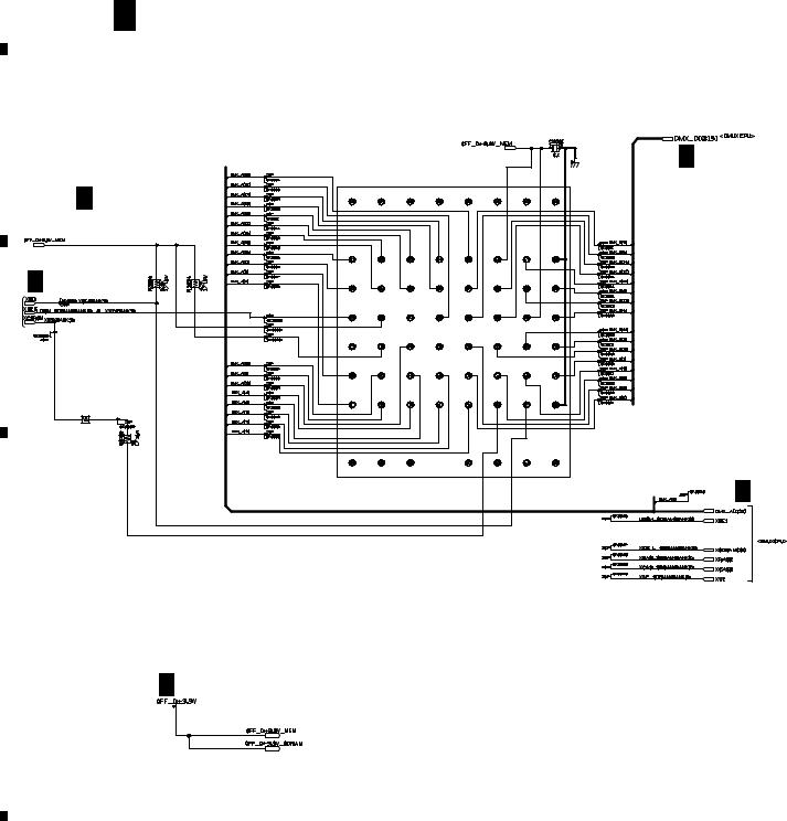
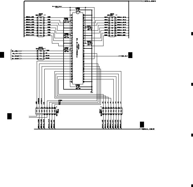
3.5 MAIN ASSY(3/8)
A
A 3/8 MAIN ASSY (3/8)
 MEMORY BLOCK
(TS7 |
: |
BWE1129) |
(BCT-1710 |
: |
BWE1130) |
(BCT-1720 |
: |
BWE1131) |
(BCT-1730 |
: |
BWE1143) |
B
A 7/7
A 2/8 |
|
C |
|
R3106 |
|
0 |
|
1/16W |
|
D |
|
IC3001 |
16M FLASH |
|
(TS7 |
: BGC1079-A-RD) |
|
|
(BCT-1710 |
: BGC1080-A-RD) |
|
|
(BCT-1720 |
: |
BGC1081-A-RD) |
|
(BCT-1730 |
: |
BGC1082-A-RD) |
|
|||
A 2/8
A 2/8
A 7/8
E
F
18 |
A |
3/8 |
|
TS7, BCT-1710, BCT-1720, BCT-1730 |
|
1 |
|
2 |
|
3 |
|
4 |
|
|
|
|
|
|
||||
|
|
|
|
|
|
5 |
|
6 |
|
7 |
|
8 |
|
|
|
|
|
|
A
|
|
|
|
|
|
|
|
64MBit SDRAM |
A |
2/8 |
|
B
A 2/8 |
A 2/8 |
A 2/8

A 2/8
C
D
E
F
|
|
A |
3/8 19 |
TS7, BCT-1710, BCT-1720, BCT-1730 |
|
5 |
|
6 |
|
7 |
|
8 |
|
|
|
|
|
|
||||
|
|
|
|
|
|
1 |
|
2 |
|
3 |
|
4 |
|
|
|
|
|
|
A
B
C
D
E
3.6 MAIN ASSY(4/8)
A 4/8 |
MAIN ASSY (4/8) |
||
|
ANALOG AV BLOCK |
||
A 2/8 |
(TS7 |
: BWE1129) |
|
|
(BCT-1710 |
: |
BWE1130) |
|
(BCT-1720 |
: |
BWE1131) |
|
(BCT-1730 |
: |
BWE1143) |
A 7/8
A
A 7/8
A 2/8 
AV Switch
A 2/8 


DAC
F
20 |
A |
4/8 |
|
TS7, BCT-1710, BCT-1720, BCT-1730 |
|
1 |
|
2 |
|
3 |
|
4 |
|
|
|
|
|
|
||||
|
|
|
|
|
5 |
6 |
7 |
8 |
|
|
|
A |
A 7/8 |
|
|
|
|
|
|
B |
|
|
|
C |
|
|
|
D |
|
|
|
Analog Audio Out |
|
|
|
E |
F
|
|
A |
4/8 21 |
TS7, BCT-1710, BCT-1720, BCT-1730 |
|
5 |
|
6 |
|
7 |
|
8 |
|
|
|
|
|
|
||||
|
|
|
|
|
|
1 |
|
2 |
|
3 |
|
4 |
|
|
|
|
|
|
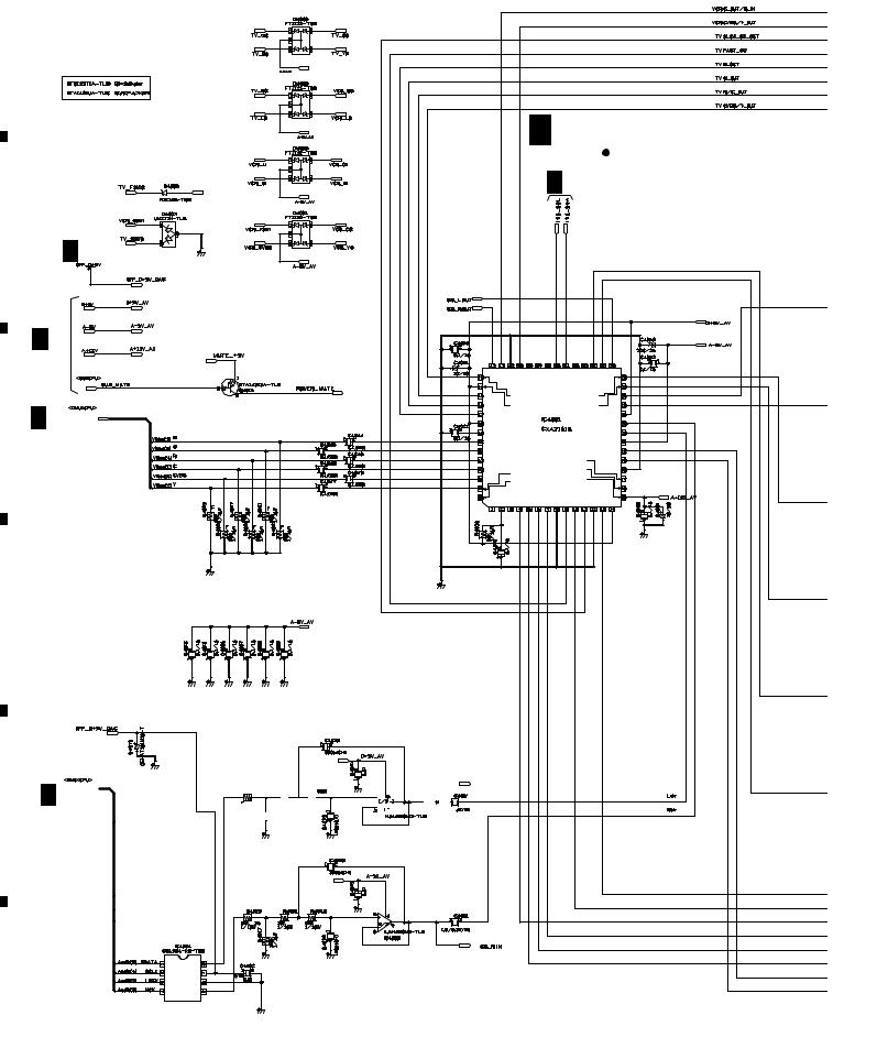
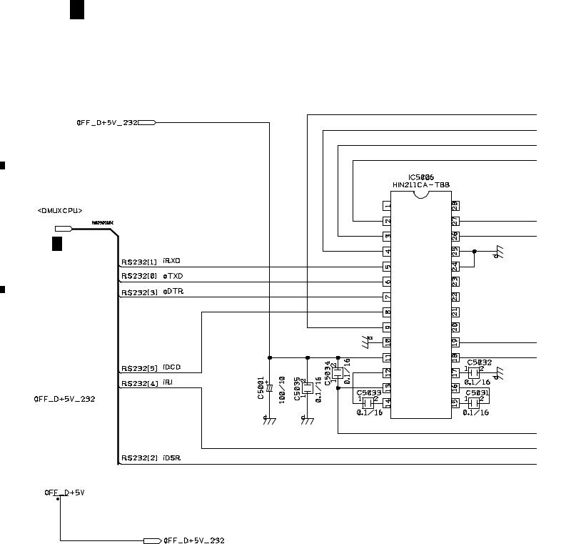
3.7 MAIN ASSY(5/8)
A
A 5/8 MAIN ASSY (5/8)
 IO BLOCK
|
(TS7 |
: |
BWE1129) |
|
|||
|
(BCT-1710 |
: |
BWE1130) |
|
(BCT-1720 |
: |
BWE1131) |
|
(BCT-1730 |
: |
BWE1143) |
B
C
A 2/8
D
|
|
|
|
RS232C Driver |
|
E |
|
||||
A |
|||||
7/8 |
|||||
|
|
|
|||
|
|
|
|
|
|
|
|
|
|
|
|
F
22 |
A |
5/8 |
|
TS7, BCT-1710, BCT-1720, BCT-1730 |
|
1 |
|
2 |
|
3 |
|
4 |
|
|
|
|
|
|
||||
|
|
|
|
|
|
5 |
|
6 |
|
7 |
|
8 |
|
|
|
|
|
|
A
B
C
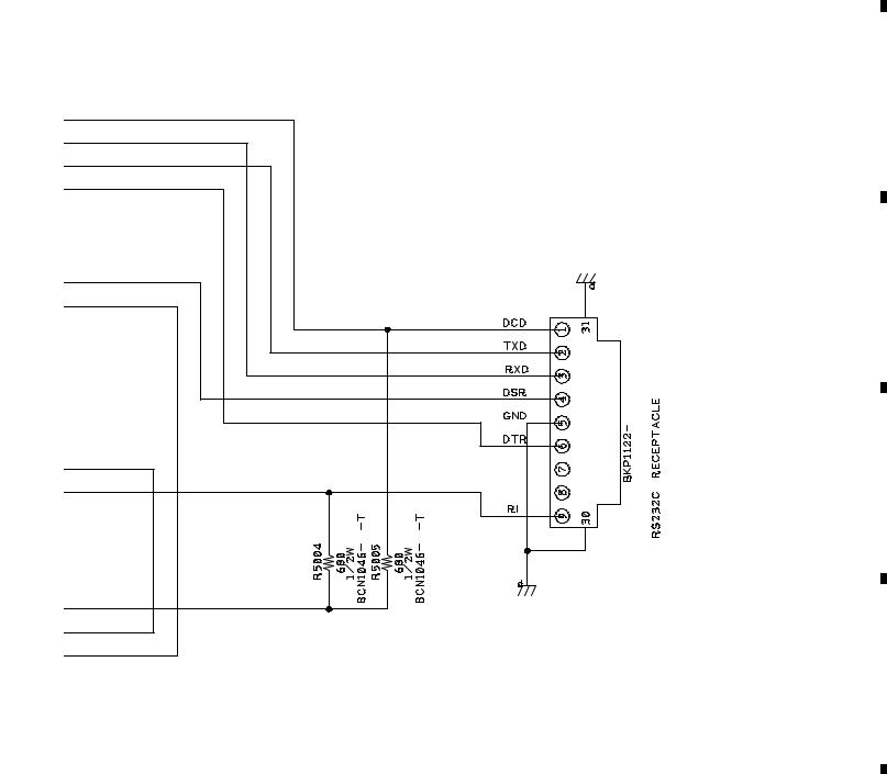
Serial I/F
CN5004
D
E
F
|
|
A |
5/8 23 |
TS7, BCT-1710, BCT-1720, BCT-1730 |
|
5 |
|
6 |
|
7 |
|
8 |
|
|
|
|
|
|
||||
|
|
|
|
|
 Loading...