


DVD AV RECEIVER
AUTORADIO AV LECTEUR DE DVD
RADIO AV CON DVD
AVH-P5100DVD
Español Français English
Installation Manual
Manuel d’installation
Manual de instalación
PyТТНЛИ

Contents |
|
Connecting the Units |
|
|
|
Connecting the Units ................................ |
1 |
Parts supplied .................................................... |
3 |
Connecting the power cord .............................. |
5 |
When connecting to separately sold power |
|
amp ............................................................ |
7 |
When connecting with a rear view camera ...... |
9 |
When connecting with a multi-channel |
|
processor .................................................. |
10 |
Connecting and installing the optical cable |
|
connection box ........................................ |
11 |
When connecting the external video |
|
component and the display ...................... |
12 |
Installation ................................................ |
13 |
DIN Front/Rear-mount .................................... |
13 |
DIN Front-mount ............................................ |
14 |
DIN Rear-mount .............................................. |
15 |
Fastening the front panel ................................ |
16 |
 WARNING
•To avoid the risk of accident and the potential violation of applicable laws, the front DVD or TV (sold separately) feature should never be used while the vehicle is being driven. Also, Rear Displays should not be in a location where it is a visible distraction to the driver.
•In some countries or states the viewing of images on a display inside a vehicle even by persons other than the driver may be illegal. Where such regulations apply, they must be obeyed and this unit’s DVD features should not be used.
CAUTION
•PIONEER does not recommend that you install or service your display yourself. Installing or servicing the product may expose you to risk of electric shock or other hazards. Refer all installation and servicing of your display to authorized Pioneer service personnel.
•Secure all wiring with cable clamps or electrical tape. Do not allow any bare wiring to remain exposed.
•Do not drill a hole into the engine compartment to connect the yellow lead of the unit to the vehicle battery. Engine vibration may eventually cause the insulation to fail at the point where the wire passes from the passenger compartment into the engine compartment. Take extra care in securing the wire at this point.
•It is extremely dangerous to allow the display lead to become wound around the steering column or gearshift. Be sure to install the display in such a way that it will not obstruct driving.
•Make sure that wires will not interfere with moving parts of the vehicle, such as the gearshift, parking brake or seat sliding mechanism.
•Do not shorten any leads. If you do, the protection circuit may fail to work properly.
 WARNING
LIGHT GREEN LEAD AT POWER CONNECTOR IS DESIGNED TO DETECT PARKED STATUS AND MUST BE CONNECTED TO THE POWER SUPPLY SIDE OF THE PARKING BRAKE SWITCH. IMPROPER CONNECTION OR USE OF THIS LEAD MAY VIOLATE APPLICABLE LAW AND MAY RESULT IN SERIOUS INJURY OR DAMAGE.
1

Note:
•This unit cannot be installed in a vehicle without ACC (accessory) position on the ignition switch.
|
|
CC |
|
|
|
|
|
|
|
|
|
F |
A |
O |
|
|
|
F |
O |
|
|
|
|
N |
|
N |
||||||
O |
F |
|
|
|
|
O |
F |
|
|
|
|
|
|
|
S |
|
|
|
S |
||
|
|
|
|
|
|
|
|
|
||
|
|
|
|
|
T |
|
|
|
|
T |
|
|
|
|
R |
A |
|
|
|
R |
A |
|
|
|
T |
|
|
|
T |
|
||
|
|
|
|
|
|
|
|
|
||
ACC position |
No ACC position |
|||||||||
•Use this unit in other than the following conditions could result in fire or malfunction.
—Vehicles with a 12-volt battery and negative grounding.
—Speakers with 50 W (output value) and 4 ohm to 8 ohm (impedance value).
•To prevent short-circuit, overheating or malfunction, be sure to follow the directions below.
—Disconnect the negative terminal of the battery before installation.
—Secure the wiring with cable clamps or adhesive tape. To protect the wiring, wrap adhesive tape around them where they lie against metal parts.
—Place all cables away from moving parts, such as gear shift and seat rails.
—Place all cables away from hot places, such as near the heater outlet.
—Do not pass the yellow cable through a hole into the engine compartment to connect to a battery.
—Cover any disconnected cable connectors with insulating tape.
—Do not remove RCA caps if RCA cables are not used.
—Do not shorten any cables.
—Never cut the insulation of the power cable of this unit in order to share the power to other equipment. Current capacity of the cable is limited.
—Use a fuse of the rating prescribed.
—Never wire the speaker negative cable directly to ground.
—Never band together multiple speaker’s nega-
tive cables.
•Control signal is output through blue/white cable when this unit is powered on. Connect it to an external power amp’s system remote control or the vehicle’s auto-antenna relay control terminal (max. 300 mA, 12 V DC). If the vehicle is equipped with a glass antenna, connect it to the antenna booster power supply terminal.
•Never connect blue/white cable to external power amp’s power terminal. Also, never connect it to the power terminal of the auto antenna. Otherwise, battery drain or malfunction may result.
•IP-BUS connectors are color-coded. Be sure to connect connectors of the same color.
•Black cable is ground. This cable and other product’s ground cable (especially, high-current products such as power amp) must be wired separately. Otherwise, fire or malfunction may result if they are accidentally detached.
PyТТНЛИ Nederlands Italiano Franзais Deutsch Espaсol English
2
Connecting the Units
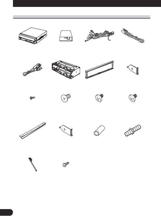
Parts supplied
This product
USB cable
Screw (2 mm × 3 mm) (4 pcs.) (pre-installed)
Tuner box |
Power cord |
Antenna cable |
Mounting sleeve |
Trim ring |
Side bracket (small) |
(pre-installed) |
(pre-installed) |
(2 pcs.) (pre-installed) |
Flush surface screw |
Binding screw |
Binding screw |
(5 mm × 6 mm) (6 pcs.) |
(5 mm × 6 mm) |
(4 mm × 3 mm) |
(2 are pre-installed.) |
(4 pcs.) |
(4 pcs.) |
Concealing tape |
Side bracket (large) |
Rubber bush |
Double-ended screw |
|
(2 pcs.) |
||||
|
|
|
Touch panel pen
Screw (2 mm × 7 mm) (2 pcs.)
3

English |
Español |
Deutsch |
Français |
Italiano |
Nederlands |
PyТТНЛИ |
4
Connecting the Units
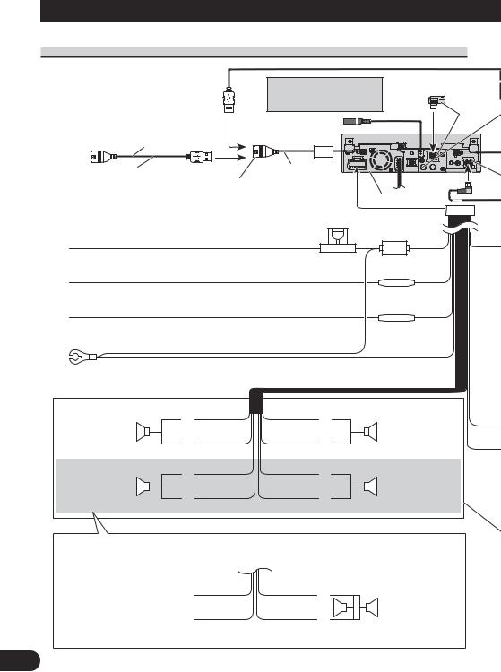
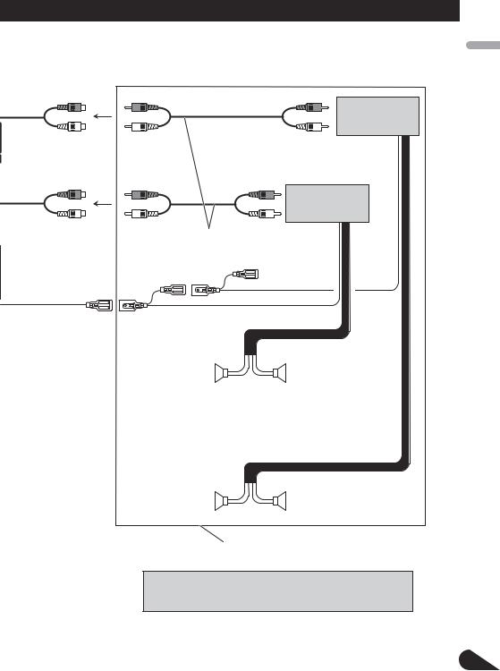
Connecting the power cord
1.5 m (4 ft. 11 in.)
USB cable (supplied) Connect to separately sold USB device.
Use a mini plug cable to connect with auxiliary
equipment. 
 Gray
Gray
AUX jack (3.5 ø) 
20 cm (7-7/8 in.)
USB input
This product
Fuse (10 A)
Yellow
Connect to the constant 12 V supply terminal.
Red
Connect to terminal controlled by ignition switch (12 V DC).
Orange/white
Connect to lighting switch terminal.
Black (chassis ground)
Connect to a clean, paint-free metal location.
|
White |
Gray |
Front speaker |
+ |
|
|
|
|
|
≠ |
|
Left |
White/black |
Gray/black |
Green Violet
Fuse resistor
Fuse resistor
+
Front speaker
≠
Right
Rear speaker or |
|
+ |
+ |
|
Rear speaker or |
Subwoofer (4 Ω) |
|
≠ |
≠ |
|
Subwoofer (4 Ω) |
|
|
||||
|
|
|
|
||
|
|
Green/black |
Violet/black |
|
|
When using a subwoofer of 70 W (2 Ω), be sure to connect with Violet and Violet/black leads of this unit. Do not connect anything to Green and Green/black leads.
Green |
Violet |
+ |
|
Not used. |
|
|
Subwoofer (4 Ω) |
|
|
||
|
|
× 2 |
|
Green/black |
Violet/black |
|
|
≠ |
|||
|
|
|
|
5
|
|
|
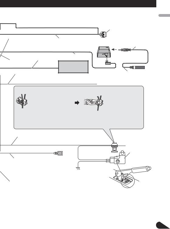
Dock connector |
|
|
|
Connect to separately sold iPod. |
Wired remote input |
|
Interface cable (e.g., CD-IU205V) |
|
Hard-wired remote control adaptor |
|
||
(sold separately) |
80 cm (2 ft. 7 in.) |
||
can be connected (sold separately). |
|
||
|
|
||
|
|
80 cm (2 ft. 7 in.) |
Tuner box (supplied) |
IP-BUS input |
IP-BUS cable |
|
|
(Blue) |
|
Multi-CD player |
|
|
|
(sold separately) |
Antenna cable |
Yellow/black |
|
|
|
|
|
|
|
If you use an equipment with Mute function, wire this lead to the Audio Mute lead on (supplied) |
|||
that piece of equipment. If not, keep the Audio Mute lead free of any connections. |
|||
Connection method |
|
|
|
|
1. Clamp the lead. |
2. Clamp firmly with |
|
|
|
|
needle-nosed pliers. |
Note:
•The position of the parking brake switch depends on the vehicle model. For details, consult the vehicle Owner’s Manual or dealer.
Light green
Used to detect the ON/OFF status of the parking brake. This lead must be connected to the power supply side of the parking brake switch.
|
Parking brake |
Power supply side |
switch |
Blue/white
Connect to system control terminal of the power Ground side amp or auto-antenna relay control terminal
(max. 300 mA 12 V DC).
With a 2 speaker system, do not connect anything to the speaker leads that are not connected to speakers.
When you connect the separately sold multi- |
|
Note: |
channel processor (e.g., DEQ-P8000) to this |
|
• Change the initial setting of this unit (refer to the |
unit, do not connect anything to the speaker |
|
Operation Manual). The subwoofer output of this unit |
leads and system remote control |
|
is monaural. |
(blue/white). |
|
|
|
|
|
|
|
|
PyТТНЛИ Nederlands Italiano Franзais Deutsch Espaсol English
6
Connecting the Units
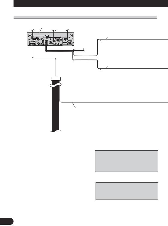
When connecting to separately sold power amp
This product
Rear output or subwoofer output (REAR/SUBWOOFER/DEQ OUTPUT)
15 cm (5-7/8 in.)
Front output (FRONT OUTPUT)
15 cm (5-7/8 in.)
Blue/white
Connect to system control terminal of the power amp or auto-antenna relay control terminal (max. 300 mA 12 V DC).
When you connect the separately sold multichannel processor (e.g., DEQ-P8000) to this unit, do not connect anything to the speaker leads and system remote control (blue/white).
When you connect the multi-channel processor to this unit, refer to multi-channel processor’s installation manual for the connection method.
7
Power amp (sold separately)
Power amp (sold separately)
Connect with RCA cables (sold separately)
System remote control
Left |
Right |
+ |
+ |
Front speaker |
Front speaker |
≠ |
≠ |
Rear speaker |
+ |
+ |
Rear speaker |
or subwoofer |
≠ |
≠ |
or subwoofer |
|
|
Perform these connections when using the optional amplifier.
Note:
•Change the initial setting of this unit (refer to the Operation Manual). The subwoofer output of this unit is monaural.
PyТТНЛИ Nederlands Italiano Franзais Deutsch Espaсol English
8
Connecting the Units
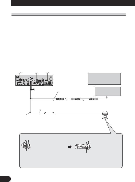
When connecting with a rear view camera
When this product is used with a rear view camera, it is possible to automatically switch from the video to rear view image when the gear shift is moved to REVERSE (R).
 WARNING
USE INPUT ONLY FOR REVERSE OR MIRROR IMAGE REAR VIEW CAMERA. OTHER USE MAY RESULT IN INJURY OR DAMAGE.
 CAUTION
•The screen image may appear reversed.
•The rear view camera function is to be used as an aid for backing into a tight parking spot. Do not use this function for entertainment purposes.
•Objects in the rear view may appear closer or more distant than they actually are.
 This product
Rear view camera input (REAR VIEW CAMERA IN)
 CAUTION
You must use a camera which outputs mirror reversed images.
Rear view camera
|
|
|
|
|
|
|
|
|
To video output |
|
|
|
|
|
|
|
|
|
|
20 cm (7-7/8 in.) |
RCA cable |
||||||||
15 cm (5-7/8 in.) |
(sold separately) |
|
|||||||
|
|
|
|
|
|||||
Connection method
1. Clamp the lead. |
2. Clamp firmly with |
|
needle-nosed pliers. |
Note:
•It is necessary to set CAMERA POLARITY properly in SYSTEM MENU when connecting the rear view camera.
9

When connecting with a multi-channel processor
This product |
25 cm |
|
|
|
Video input |
||
|
(9-7/8 in.) |
(VIDEO INPUT) |
|
IP-BUS cable |
IP-BUS input (Blue) |
||
Blue |
|
||
(supplied with DVD |
DEQ output (REAR/ |
||
player) |
|||
SUBWOOFER/DEQ OUTPUT) |
|||
|
|||
Black |
15 cm (5-7/8 in.) |
||
|
|||
|
Optical cable (supplied with |
RCA cable (supplied with |
|
Optical cable connection box |
multi-channel processor) |
||
multi-channel processor) |
|||
(supplied with multi-channel |
|
|
|
processor) |
Optical cable (sold |
DVD player (e.g., XDV-P6) |
|
|
|||
|
separately) |
(sold separately) |
|
Blue
Black
Hide-away unit (supplied  with DVD player)
Blue
Front video output (Yellow)
Multi-channel processor (e.g., DEQ-P8000) (sold separately)
Black |
Blue |
Black
 Black
Black
25 pin cable (supplied with DVD player)
RCA cable (supplied with DVD player)
IP-BUS cable
IP-BUS cable (supplied with multi-channel processor)
When you connect a separately sold DVD player to the separately sold multi-channel processor, the optical cable from DVD player must be connected to the optical cable 2 input (OPT. IN2) of the multi-channel processor.
You can use only one video component with this unit.
Multi-CD player (sold separately)
PyТТНЛИ Nederlands Italiano Franзais Deutsch Espaсol English
10
Connecting the Units
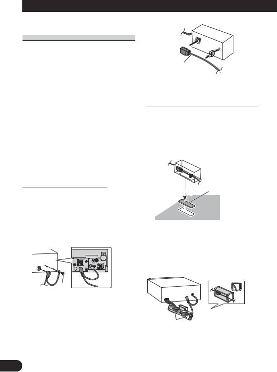
Connecting and installing the optical cable connection box
 WARNING
•Avoid installing this unit in locations where the operation of safety devices such as airbags is prevented by this unit. Otherwise, there is a danger of a fatal accident.
•Avoid installing this unit in locations where the operation of the brake may be prevented. Otherwise, it may result in a traffic accident.
•Fix this unit securely with the hook and loop fastener or lock tie. If this unit is loose, it disturbs driving stability, which may result in a traffic accident.
 CAUTION
•Install this unit using only the parts supplied with this unit. If other parts are used, this unit may be damaged or could dismount itself, which leads to an accident or other problems.
•Do not install this unit near the doors where rainwater is likely to be spilled on the unit. Incursion of water into the unit may cause smoke or fire.
Connecting the optical cable
1.Connect the optical cable and ground lead to the main unit.
Connect the optical cable so that it does not protrude from the unit, as shown in the illustration. Fasten the ground lead to the protrusion on the back of the unit.
Screw
2.Connect the optical cable to the optical cable connection box.
Optical cable
Installing the optical cable connection box
•When installing the optical cable connection box with the hook and loop fastener.
Install the optical cable connection box using the hook and loop fastener in the ample space of the console box.
Hook fastener
 Loop fastener
•When installing the optical cable connection box with the lock tie.
Wrap the optical cable and connection box with the protection tape and fasten with the power code using the lock tie.
Wrap with the protection tape
Fasten with the lock tie
11
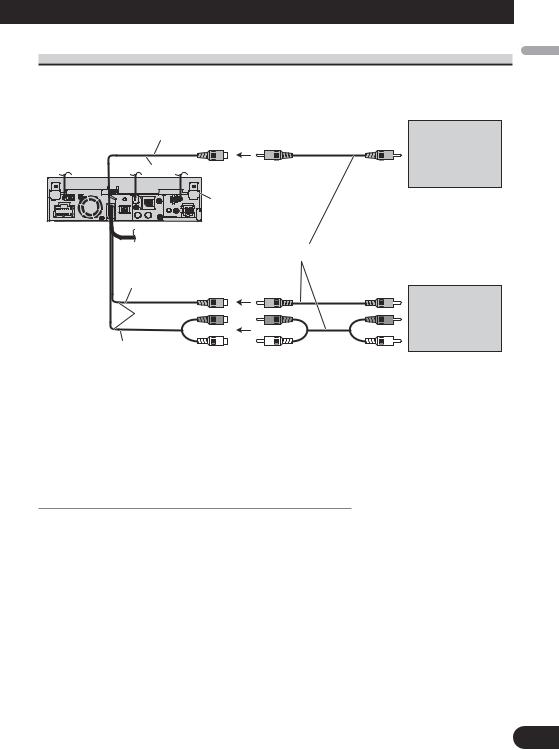
When connecting the external video component and the display
Rear monitor output |
|
|
(REAR MONITOR OUTPUT) |
To video input |
Display with |
|
||
|
|
RCA input jacks |
20 cm (7-7/8 in.) |
|
(sold separately) |
This product |
|
|
RCA cables (sold separately) |
|
|
Video input |
|
|
(VIDEO INPUT) |
To video output |
|
|
|
|
25 cm |
|
External video |
|
component |
|
(9-7/8 in.) |
|
|
|
(sold separately) |
|
|
|
|
Audio input |
To audio outputs |
|
(AUDIO INPUT) |
|
|
|
|
|
•It is necessary to set AV INPUT to VIDEO in SYSTEM MENU when connecting the external video component.
•It is necessary to set AV INPUT to S-DVD in SYSTEM MENU when connecting a multi-DVD player.
When using a display connected to rear video output
This product’s rear video output is for connection of a display to enable passengers in the rear seats to watch the DVD or Video CD.
 WARNING
•NEVER install the display in a location that enables the Driver to watch the DVD or Video CD while driving.
PyТТНЛИ Nederlands Italiano Franзais Deutsch Espaсol English
12
Installation
Note:
•Check all connections and systems before final installation.
•Do not use unauthorized parts. The use of unauthorized parts may cause malfunctions.
•Consult with your dealer if installation requires drilling of holes or other modifications of the vehicle.
•Do not install this unit where:
—it may interfere with operation of the vehicle.
—it may cause injury to a passenger as a result of a sudden stop.
•Do not install the display where it may (i) obstruct the driver’s vision, (ii) impair the performance of any of the vehicle’s operating systems or safety features, including air bags, hazard lamp buttons or (iii) impair the driver’s ability to safely operate the vehicle.
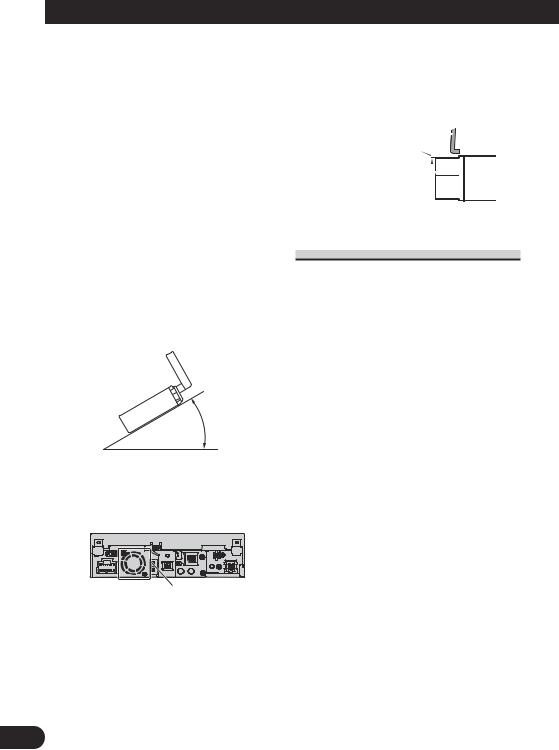
•The semiconductor laser will be damaged if it overheats. Install this unit away from hot places such as near the heater outlet.
•Optimum performance is obtained when the unit is installed at an angle of less than 30°.
30°
•The cords must not cover up the area shown in the figure below. This is necessary to allow the amplifires to radiate freely.
Do not cover this area.
•Make sure you leave enough gap between the dashboard and the LCD panel of this unit so the LCD panel can be opened and closed without contacting with the dashboard.
Dashboard
Leave gap
LCD panel
DIN Front/Rear-mount
This unit can be properly installed either from “Front” (conventional DIN Front-mount) or “Rear” (DIN Rearmount installation, utilizing threaded screw holes at the sides of unit chassis). For details, refer to the following illustrated installation methods.
13
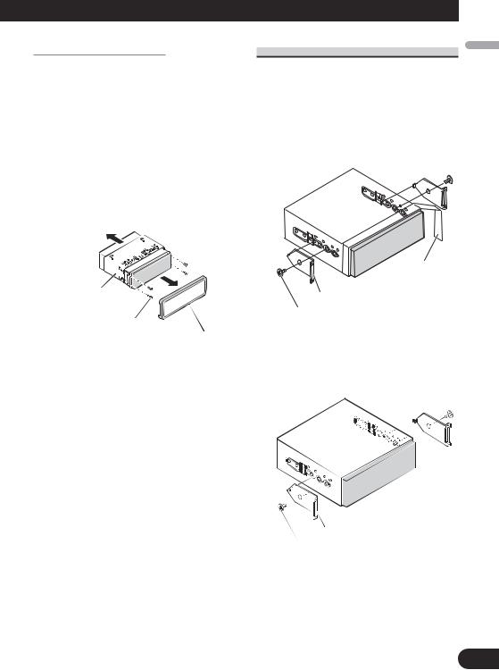
Before installing the unit
•Remove the trim ring and the mounting sleeve.
Extend top and bottom of the trim ring
outwards to remove the trim ring. And then loosen the screws (2 mm × 3 mm) to remove the mounting sleeve.
•When reattaching the trim ring, push the trim ring onto the unit until it clicks after reattaching the mounting sleeve. (If the trim ring is attached upside down, the trim ring will not fit properly.)
Mounting sleeve
Screw (2 mm × 3 mm)
Trim ring
DIN Front-mount
1.Decide the position of the side brackets.
•When installing in a shallow space, change the position of side brackets (small). In this case, stick concealing tape on parts that protrude from the dashboard.
Concealing tape
Side bracket (small)
Flush surface screw (5 mm × 6 mm)
•If you prefer an off-set installation in which the front panel is pushed further back, when there is a space available at the back of the unit, use the side brackets (large).
Side bracket (large)
Flush surface screw (5 mm 6 mm)
PyТТНЛИ Nederlands Italiano Franзais Deutsch Espaсol English
14
 Loading...