


Color LCD Display
Owner’s Manual
AVD-W6010
This product conforms to new cord colors.
Los colores de los cables de este producto se conforman con un nuevo código de colores.
Dieses Gerät entspricht den neuen kabelfarben.
ITALIANO FRANÇAIS DEUTSCH ESPAÑOL ENGLISH
NEDERLANDS

Contents |
|
Contents ...................................................... |
1 |
IMPORTANT SAFEGUARDS .................... |
2 |
Please Read All of These Instructions |
|
Regarding Your Display and Retain |
|
them for Future Reference ........................ |
2 |
Fitting and Removing the Display .......... |
3 |
To fit the display .............................................. |
3 |
To remove the display ...................................... |
3 |
IMPORTANT INFORMATION .................... |
4 |
About This Product .......................................... |
4 |
Precaution .......................................................... |
4 |
In Case of Trouble ............................................ |
4 |
Before Using This Product ...................... |
5 |
To Avoid Battery Exhaustion ............................ |
5 |
To Protect the LCD Screen of the Display ........ |
5 |
When Viewing is Difficult, use [BRIGHT] and |
|
[DIMMER] to Adjust ................................ |
5 |
To Ensure Safe Driving .................................... |
6 |
Resetting the Microprocessor ............................ |
6 |
Key Finder .................................................... |
7 |
Component Parts and Features .......................... |
7 |
Basic Operation ........................................ |
8 |
Turn On Power .................................................. |
8 |
Volume Adjustment .......................................... |
8 |
Selecting the Source .......................................... |
9 |
-About the Corner Icons
-About the RCA Video and Audio Outputs of this Unit
Selecting the Audio, Video, and External |
|
Output........................................................ |
10 |
-Selecting the Video for the Display Independently
-Selecting the Audio for Built-in Speaker Independently
Changing the Wide Screen Mode .................... |
12 |
- Wide Modes Available |
|
Operating the Setup Menu .................... |
14 |
Entering the Setup Menu ................................ |
14 |
Picture Adjust .................................................. |
15 |
-BRIGHT/CONTRAST/COLOR/HUE
-DIMMER
Input Setting [VCR1/VCR2] .......................... |
17 |
Display Setting ................................................ |
18 |
-Setting the Mixing of the Guidance Voice [MIXING]
Forced VCR1 Input Setting ............................ |
19 |
Using the Display Correctly .................. |
20 |
Handling the Display ...................................... |
20 |
About the Liquid Crystal Display (LCD) |
|
Screen ...................................................... |
21 |
Keeping the Display in Good Condition ........ |
21 |
About the Small Fluorescent Tube .................. |
21 |
Connecting the System .......................... |
22 |
Names and Functions of Connection |
|
Terminals .................................................. |
24 |
Connecting the Power Cable .......................... |
25 |
Connection Diagram (VCR input) .................. |
26 |
Connection Diagram (RGB input) .................. |
27 |
Connecting RCA Audio and Video Output .... |
28 |
Connecting “AUTOMATIC INPUT |
|
SWITCHING” Lead ................................ |
29 |
Installation ................................................ |
30 |
Before Installing and Fixing ............................ |
31 |
Before Affixing the Adhesive Tape ................ |
31 |
Installing the Display Using the Accessory |
|
Mounting Base ........................................ |
32 |
Installing the Hide-away Unit ........................ |
35 |
- Installation Precautions |
|
- Hide-away Unit Installation |
|
Specifications .......................................... |
36 |
1

IMPORTANT SAFEGUARDS
Please Read All of These Instructions Regarding Your Display and Retain them for Future Reference
1.Read this manual fully and carefully before operating your display.
2.Keep this manual handy for future reference.
3.Pay close attention to all warnings in this manual and follow the instructions carefully.
4.Never allow others to use the system until they have read and understood the operating instructions.
5.Do not install the display where it may (i) obstruct the driver’s vision, (ii) impair the performance of any of the vehicle’s operating systems or safety features, including airbags, or (iii) impair the driver’s ability to safely operate the vehicle.
6.As with any accessory in your vehicle’s interior, the display should not divert your attention from the safe operation of your vehicle. If you experience difficulty in operating the system or reading the display, please park safely before making adjustments.
7.Do not attempt to install or service your display by yourself. Installation or servicing of the display by persons without training and experience in electronic equipment and automotive accessories may be dangerous and could expose you to the risk of electric shock or other hazards.
8.Please remember to wear your seat belt at all times while operating your vehicle. If you are ever in an accident, your injuries can be considerably more severe if your seat belt is not properly buckled.
9.Use of this product is subject to any local laws regarding placement or use. PIONEER Corporation cannot accept any liability for any problems, damage or loss incurred as a result of the product being used with an incorrect setting or in violation of any local laws.
10.This function is designed for use with a back-up camera only. Users may connect the VTR 1 input with “AUTOMATIC INPUT SWITCHING” only to such a back-up camera. Users must not connect any other devices to the VTR 1 input with “AUTOMATIC INPUT SWITCHING”.
NEDERLANDS ITALIANO AISÇFRAN DEUTSCH OLÑESPA ENGLISH
2

Fitting and Removing the Display
Precaution:
•To prevent failure, be sure to turn the ignition switch or system power OFF before fitting or removing the display. Also take care not to grip the screen or buttons too firmly or to drop the display.
•Do not let any water get on the terminals on the display or on the base and do not allow the terminals to be shorted by a metal object or the like. This can cause system breakdown.
•Be careful not to touch terminals on the display or on the base. Doing so may cause connection failures. If any terminals are stained, wipe them with a clean dry cloth.
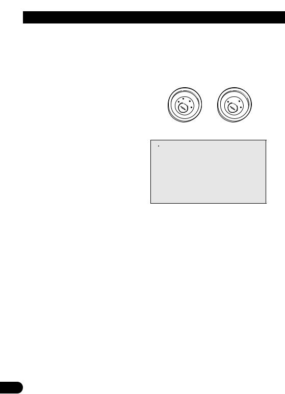
To fit the display
1. Fit part 1 of the display into the |
2. Slide the display downward until it |
grooves 2 on the left and right of |
clicks into place. |
the base. |
|
Base |
|
To remove the display
• Pull the lock release lever 3 upward and hold in that position, then slide the display upward and detach it from its base.
• To prevent theft of the display, remove
the display when leaving the vehicle. |
Base |
|
3

IMPORTANT INFORMATION
About This Product
•This product complies with the EMC Directives (89/336/EEC, 92/31/EEC) and CE Marking Directive (93/68/EEC).
•Do not place the display in a position where it will impede the driver’s visibility or affect the operation of your vehicle’s airbags.
Precaution
•Always keep the volume low enough for outside sounds to be audible.
•Protect the product from moisture.
In Case of Trouble
Should this product fail to operate properly, contact your dealer or the nearest authorized Pioneer service facility.
NEDERLANDS ITALIANO AISÇFRAN DEUTSCH OLÑESPA ENGLISH
4

Before Using This Product
To Avoid Battery Exhaustion
Always run the vehicle engine while using this unit. Using this unit without running the engine can result in battery drainage.
To Protect the LCD Screen of the Display
•Do not allow direct sunlight to fall on the Display when this unit is not being used. Extended exposure to direct sunlight can result in LCD screen malfunction due to the resulting high temperatures.
•When using a portable phone, keep the antenna of the portable phone away from the Display to prevent disruption of the video by the appearance of spots, colored stripes, etc.
When Viewing is Difficult, use [BRIGHT] and [DIMMER] to Adjust
Due to its construction, the view angle of the LCD screen is limited. The viewing angle (vertical and horizontal) can be increased, however, by using [BRIGHT] to adjust the black density of the video. When using for the first time, adjust the black density in accordance with the viewing angle (vertical and horizontal) to adjust for clear viewing. [DIMMER] can also be used to adjust the brightness of the LCD screen itself to suit your personal preference.
5
To Ensure Safe Driving
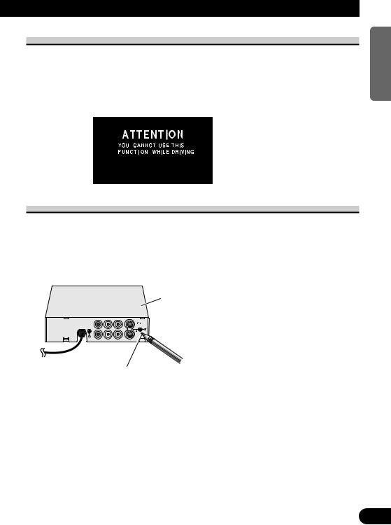
This unit senses whether the parking brake is on or off. When installed, it is arranged so that video cannot be viewed while the vehicle is moving. (except for navigation unit.) The various settings and adjustments are also not possible while driving. (The following message will be displayed on the screen while the vehicle is moving.)
Stop the vehicle in a safe place apply the parking brake and wait for the message to clear before starting operation.
Resetting the Microprocessor
The microprocessor must be reset under the following conditions:
When using this product for the first time after installation
When the product fails to operate properly
When strange (incorrect) messages appear on the display
•To reset the microprocessor, press the RESET button on the unit with a pen tip or other pointed instrument.
Hide-away Unit
RESET button
NEDERLANDS ITALIANO AISÇFRAN DEUTSCH OLÑESPA ENGLISH
6

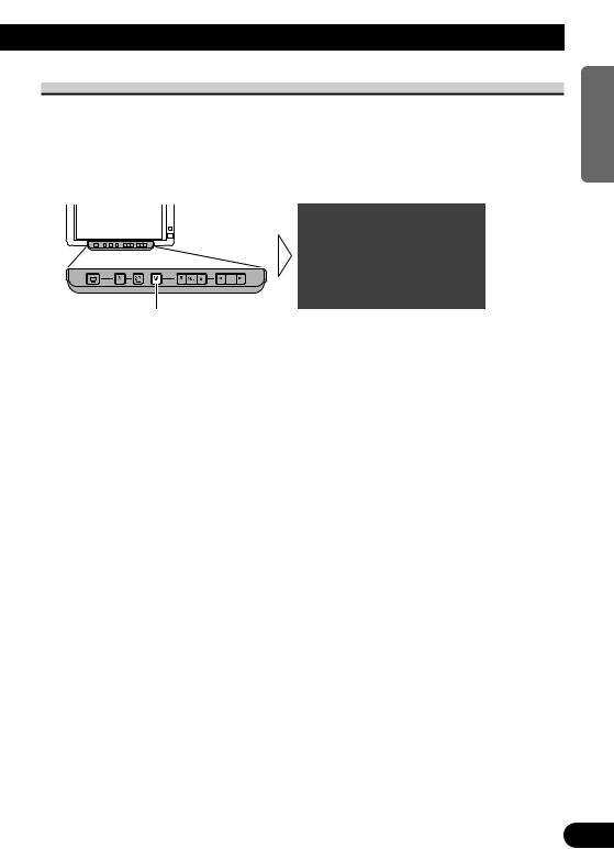
Key Finder
Component Parts and Features
1SEL/POWER button
Selects the system’s audio and video simultaneously. If AV equipment is connected to the system’s RCA audio and video output terminals, the audio and video of the source selected with this button are generated.
Pressing this button for 2 seconds also switches power ON/OFF.
2V.SEL button
Selects only the display’s video.
3SP.SEL button
Selects only the built-in speaker’s audio.
4WIDE/MENU button
Changes the method of enlarging 4:3 video to 16:9 video. Pressing this button for 2 seconds, and displayed the setup menu. Once the setup menu is displayed, its menu is switched each time the button is pressed.
5Volume control (∞/5) buttons
Adjust the volume of the built-in speaker 9, or change setup items when the setup menu is displayed.
Note:
•Never set the volume so high that you cannot hear outside traffic and emergency vehicles.
62/3 buttons
Adjust the item when the setup menu is displayed.
7Ambient light sensor
Senses ambient light. This system automatically adjusts the brightness of the display to compensate for ambient light.
8Signal receptor
This receiver receives signals from the remote controller supplied with the mobile navigation unit and other AV equipment.
9Built-in speaker
Outputs sound from audio equipment connected to this product.
0 Lock release lever
(Refer to page 3.)
7
Basic Operation
Turn On Power
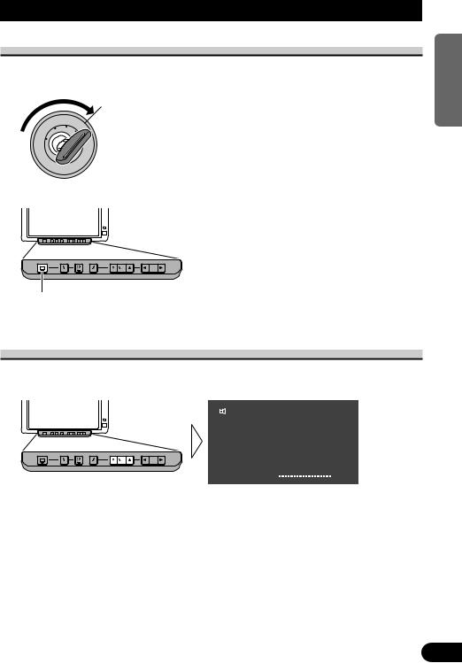
Remember to start the car engine before turning on the power to preserve battery life.
1. Start the car engine.
OC
L
2. Turn on the system.
Hold for 2 seconds
Each press of the SEL/POWER button for 2 seconds, the power of the system ON/OFF.
Volume Adjustment
Adjust the volume of audio output from the built-in speaker.
• Raise or lower the speaker volume.
VCR 1
VOL |
|
|
|
|
|
|
|
|
|
|
|
|
|
|
|
|
|
|
|
|
|
|
|
12 |
|
|
|
|
|
|
|
|
|
|
|
|
The volume of the built-in speaker can be adjusted in a range of 0 to 30. (The volume level will be displayed for about 4 seconds.)
NEDERLANDS ITALIANO AISÇFRAN DEUTSCH OLÑESPA ENGLISH
8
Basic Operation
Selecting the Source
You can switch the selected sources of three icons simultaneously, or switch them separately.
About the Corner Icons
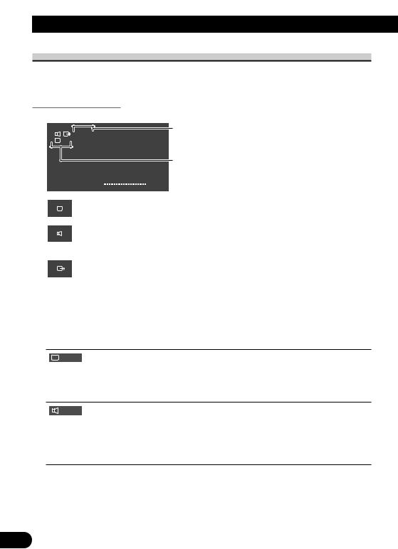
The following icons are displayed in the upper left corner of the Screen.
Icons indicate the selected sources.
VCR 1
VCR 1
The upper icons are selected with the SEL/POWER button.
The lower icons are selected independently.
VOL |
|
|
|
|
|
|
|
|
|
|
|
|
|
|
|
|
|
|
|
|
|
|
|
12 |
|
|
|
|
|
|
|
|
|
|
|
|
|||||||||||||
|
|
|
|
|
|
|
|
|
|
|
|
Display icon:
Indicates the video on the display.
Built-in speaker icon:
Indicates the audio output from the built-in speaker of this unit.
(When you switch MIXING ON, this icon is turned red.) (Refer to page 18.)
RCA output icon:
Indicates the video and audio output from the RCA output jack of the hide-away unit.
Icons condition |
|
Button for source change |
||||||
|
|
|
|
|
|
|
|
SEL/POWER button |
|
|
|
|
|
|
|
|
|
|
|
|
|
|
|
|
|
|
For RCA output, you can only switch the source with the
SEL/POWER button.
V.SEL button
Press the V.SEL button for 2 seconds to switch only the display out of three sources; display, built-in speaker and RCA output. To return to the setting for selecting all source at the same time, press the V.SEL button again for 2 seconds.
SP.SEL button
Press the SP.SEL button for 2 seconds to switch only the built-in speaker audio out of three sources: display, built-in speaker and RCA output. To return to the setting for selecting all source at the same time, press SP.SEL button again for 2 seconds.
Note:
•After selecting the source with the V.SEL button or the SP.SEL button, you won’t be able to switch the display or built-in speaker’s audio with the SEL/POWER button until each mode is canceled.
9
About the RCA Video and Audio Outputs of this Unit
When you connect a separate piece of AV equipment such as a second display to the RCA video and audio output jacks of the hide-away unit, you can select the source for output with the SEL/POWER button,
•The video and audio source of the RCA outputs of this unit cannot be selected independently.
•The V.SEL, SP.SEL and Volume control buttons will have no effect even if operated.
 CAUTION
Never position the display connected to the RCA output jack of the hideaway unit, driver can view the picture while the vehicle is moving.
Selecting the Audio, Video, and External Output
When three icons are displayed in a line, you can simultaneously change the sources of each icon.
If Display and Built-in speaker are set for independent switching, switch them simultaneously. (Refer to pages 9 and 11.)
• Select the desired source.
VCR 1
VOL |
12 |
Each press changes the source ...
Each press of the SEL/POWER button selects the desired source in the following order: [VCR1] = [VCR2] = [RGB] = Exit to [VCR1]
Note:
•[RGB] indicates the equipment connected to the hide-away unit’s RGB input. (The source does not switch to [RGB] when nothing is connected to the RGB input.)
•[VCR1] and [VCR2] are audio and video from the AV equipment connected to the VCR1 or VCR2 input terminal. (Refer to page 24.)
•Verify the correct connection with the AV equipment connected to VCR1 or VCR2.
•VCR2 is selectable only if either [VIDEO] or [S-VIDEO] has been chosen in [INPUT SETTING] . (Refer to page 17.)
NEDERLANDS ITALIANO AISÇFRAN DEUTSCH OLÑESPA ENGLISH
10
Basic Operation
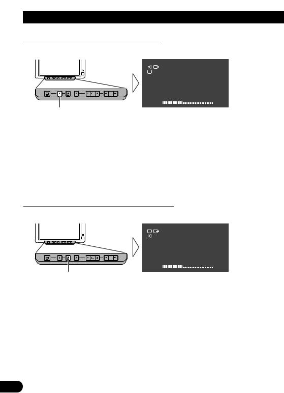
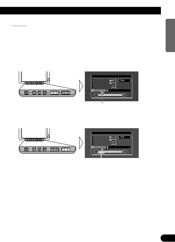
Selecting the Video for the Display Independently
1. Set so that only the display video can be selected.
VCR 1
VCR 1
VOL |
12 |
Hold for 2 seconds
2.Press V.SEL button.
Each press of the V.SEL button selects the desired video source in the following order: [VCR1] = [VCR2] = [RGB] = Exit to [VCR1]
Note:
•Return to the setting for switching all source at the same time, press the V.SEL button for 2 seconds.
•If you press the V.SEL button when video source are switched with the SEL/POWER button, [SELECTOR] appears in red on the screen, indicating that the audio and video can be switched simultaneously using the SELECTOR button.
•While switched to forced video from a back-up camera, if you try to select a video source with the V.SEL button, “INVALID” is displayed, indicating that you cannot switch the video source.
Selecting the Audio for Built-in Speaker Independently
1. Set so that only the built-in speaker audio can be switched.
VCR 1
VCR 1
VOL |
12 |
Hold for 2 seconds
2.Press SP.SEL button.
Each press of the SP.SEL button selects the desired audio source in the following order: [VCR1] = [VCR2] = [RGB] = Exit to [VCR1]
Note:
•Return to the setting for selecting all source at the same time, press the SP.SEL button for 2 seconds.
•If you press the SP.SEL button when audio are switched with the SEL/POWER button, [SELECTOR] appears in red on the screen, indicating that the audio and video can be switched simultaneously using the SELECTOR button.
11
Changing the Wide Screen Mode
You can change the way in which normal video (aspect ratio 4:3) enlarges to wide video (16:9). Select wide modes to suit the kind of video you are viewing, such as news programs and movies.
1.Display video to view. (Refer to pages 10 and 11.)
2.Select a wide mode.
JUST
Each press changes the mode ...
Each press of the WIDE/MENU button selects the wide mode in the following order: [FULL] = [JUST] = [CINEMA] = [ZOOM] = [NORMAL] = Exit to [FULL]
Note:
•Settings are stored for each source (RGB, VCR1, VCR2).
•The setup menu screen always appears in FULL mode. (Refer to page 14.)
•Always set the wide mode to [FULL] when viewing Navigation unit svideo.
•When video is viewed in a wide mode that does not match its original aspect ratio, it may appear differently.
•Remember that using the wide mode feature of this system for commercial or public viewing purposes may constitute an infringement on the author’s rights protected by the Copyright Law.
NEDERLANDS ITALIANO AISÇFRAN DEUTSCH OLÑESPA ENGLISH
12
Basic Operation
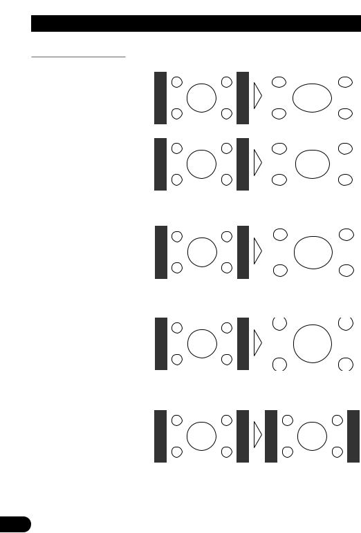
Wide Modes Available
FULL
Video with an aspect ratio of 4:3 enlarges only horizontally. Enjoy viewing video widened without missing parts.
JUST
Video appears more extended horizontally as it gets closer to both edges of the screen. Because video appears in about the same size as regular video around the middle of the screen, enjoy viewing it without feeling out of place.
CINEMA
Video enlarges vertically with a aspect ratio falling between FULL and ZOOM. This wide mode is suited for horizontally long video, such as movies, in which titles are displayed in black areas outside the video.
ZOOM
Video with an aspect ratio of 4:3 enlarges with the same aspect ratio in both vertical and horizontal directions. This wide mode is suited for horizontally long video, such as movies, in which titles overlap the video.
NORMAL
Video with an aspect ratio of 4:3 appears without enlarging. Enjoy viewing TV in the same video as it is broadcast.
Note:
•Video will appear roughened when viewed in CINEMA or ZOOM mode (When PAL video is displayed).
13
Operating the Setup Menu
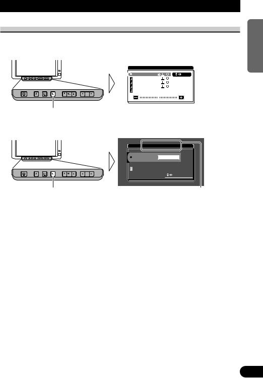
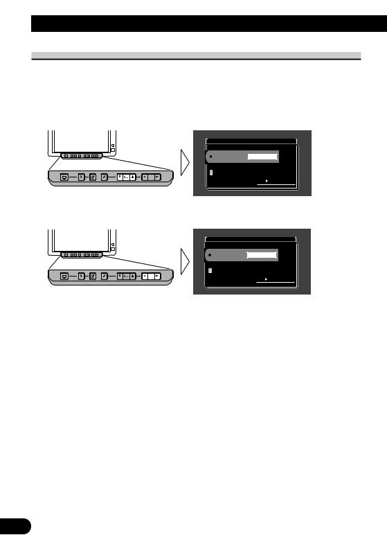
Entering the Setup Menu
This system offers a number of functionality setup and adjustment features to make it easier to use. Customize the settings to suit your taste and environment.
1. Display the setup menu screen.
P I C T U R E A D J U S T |
|
BRIGHT |
S E L |
CONTRAST |
|
COLOR |
|
HUE |
|
DIMMER |
|
|
|
Hold for 2 seconds
The menu screen is displayed.
2. Select a setup menu.
I N P U T S E T T I N G
VCR1 |
VIDEO |
V C R 2 |
NO SELECT |
|
S E L E C T |
|
|
Each press changes the menu ... Current mode
Each press of the WIDE/MENU button selects the desired menu in the following order: [PICTURE ADJUST] = [INPUT SETTING] = [DISPLAY SETTING]
= [CONTROL SETTING] = Exit the setup menu.
Exit the setup menu, return to the previous display.
NEDERLANDS ITALIANO AISÇFRAN DEUTSCH OLÑESPA ENGLISH
14
Operating the Setup Menu
Picture Adjust
BRIGHT/CONTRAST/COLOR/HUE
Settings are stored for each source (RGB, VCR1, VCR2).
Options |
Adjustment items |
Bright [BRIGHT]: |
Makes black appear darker or lighter. |
|
|
Contrast [CONTRAST]: |
Narrow or widen the gap between black and white (darken). |
|
|
Saturation [COLOR]: |
Makes colors appear lighter or darker. |
|
|
Hue [HUE]: |
Adjust red or green of picture. |
|
|
1.Display the video to adjust. (Refer to pages 10 and 11.)
2.Display a menu screen and select [PICTURE ADJUST] menu. (Refer to page 14.)
3.Select an item to adjust.
|
P I C T U R E A D J U S T |
|
|
BRIGHT |
S E L |
|
||
|
CONTRAST |
|
|
COLOR |
|
|
HUE |
|
|
DIMMER |
|
|
|
|
4. Adjust the item.
|
P I C T U R E A D J U S T |
|
|
BRIGHT |
S E L |
|
||
|
CONTRAST |
|
|
COLOR |
|
|
HUE |
|
|
DIMMER |
|
|
|
|
Either can be adjusted within the range of –24 to +24.
Note:
•The settings of [BRIGHT] and [CONTRAST] are stored separately for light ambient (daytime) and dark ambient (nighttime).
•A yellow mark (  ) or blue mark (
  ) is displayed to the right of [BRIGHT] and [CONTRAST] on the screen, respectively, as the front-panel ambient light sensor determines brightness or darkness.
•[HUE] cannot be adjusted for PAL video.
15
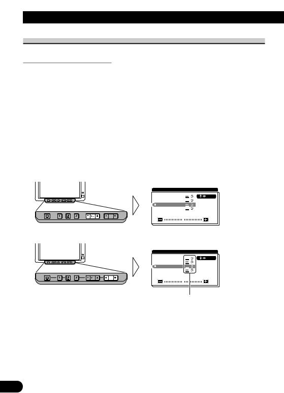
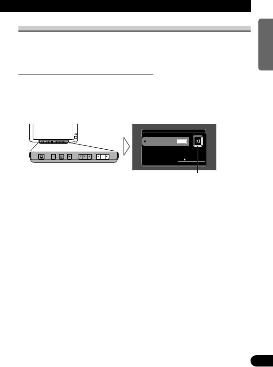
DIMMER
Viewing can become difficult after extended video viewing if the screen is too bright at night or when ambient light darkens. You can select the brightness level from three settings; daytime, evening and nighttime viewing, after which this product will automatically adjusts the brightness to an optimum level within the setting range you selected and in relationship with the ambient light.
1.Display a menu screen and select [PICTURE ADJUST] menu. (Refer to page 14.)
2.Choose [DIMMER].
P I C T U R E A D J U S T |
|
BRIGHT |
S E L |
CONTRAST |
|
COLOR |
|
HUE |
|
DIMMER |
SENSOR LEVEL |
External light level
Yellow: bright (daytime)
Red: intermediate brightness (evening)
Blue: dark (nighttime)
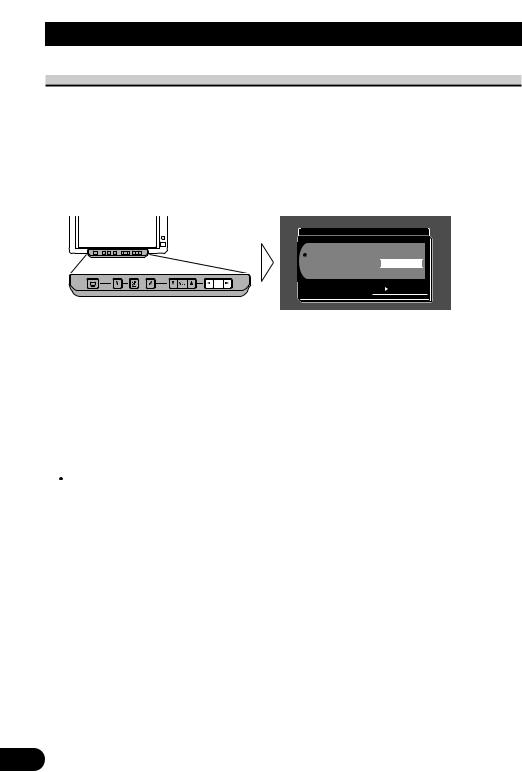
3. Adjust brightness.
P I C T U R E A D J U S T
|
BRIGHT |
S E L |
|||
|
CONTRAST |
|
|||
|
COLOR |
|
|||
|
HUE |
|
|||
|
DIMMER |
SENSOR LEVEL |
|||
|
|
|
|
|
|
|
|
|
|
|
|
This level indicates the brightness of the screen being adjusted. The farther yellow moves to the right, the brighter the screen.
Note:
•The external light level used as the standard for adjusting [DIMMER] is indicated by the mark shown in step 3 and its position. The marks indicating the current ambient brightness used for adjusting [BRIGHT] and [CONTRAST] may differ slightly.
•The external light level can be adjusted to Dark, Intermediate or Bright and the each setting saved.
NEDERLANDS ITALIANO AISÇFRAN DEUTSCH OLÑESPA ENGLISH
16
Operating the Setup Menu
Input Setting [VCR1/VCR2]
To view videos by a VCR, DVD player or any other kind of equipment connected to the hide-away unit.
1.Display a menu screen and select [INPUT SETTING] menu. (Refer to page 14.)
2.Choose between [VCR1] and [VCR2].
I N P U T S E T T I N G
VCR1 VIDEO
V C R 2 |
NO SELECT |
 S E L E C T
3.Select a connection mode.
Select the connection mode of the source external unit to the right of [VCR1] or [VCR2].
I N P U T S E T T I N G
 VCR1 S–VIDEO
V C R 2 |
NO SELECT |
 S E L E C T
Each press of the 2 or 3 button selects the source in the following order: VCR1: [VIDEO] = [S-VIDEO] = Exit to [VIDEO]
VCR2: [NO SELECT] = [VIDEO] = [S-VIDEO] = Exit to [NO SELECT]
Note:
•If the equipment is connected to a RCA video input, choose [VIDEO] to view video of the equipment. (Refer to page 24.)
•If the equipment is connected to a S-VIDEO input, choose [S-VIDEO] to view video of the equipment. (Refer to page 24.)
•If [VCR2] (NO SELECT) is chosen, the display and built-in speaker will not switch to [VCR2].
17
Display Setting
7[MIXING]
Both the audio of Navigation unit guide and the audio from video equipment, etc., can be output from the built-in speaker.
Setting the Mixing of the Guidance Voice [MIXING]
When connecting the mobile navigation unit to RGB input of this hide-away unit, you can select ON/OFF for the guidance voice from mobile navigation unit.
1.Display a menu screen and select [DISPLAY SETTING] menu. (Refer to page 14.)
2.Select the mixing ON/OFF.
D I S P L A Y S E T T I N G
|
M I X I N G |
ON |
|
|
|
 S E L E C T
When mixing ON, this mark is turned red.
[ON]: The navigation’s guidance voice is output at the same time as audio from another source.
[OFF]: The navigation’s guidance voice is not output.
NEDERLANDS ITALIANO AISÇFRAN DEUTSCH OLÑESPA ENGLISH
18
Operating the Setup Menu
Forced VCR1 Input Setting
This product features a function that automatically switches to the video input into the VCR1 jack when a back-up camera is installed on your car. If this is the case, when the gear shift is in the REVERSE (R) position, the video automatically switches to VCR1. (The initial setting is [BATTERY]. For more details, consult with your dealer.)
1.Display a menu screen and select [CONTROL SETTING] menu. (Refer to page 14.)
2.Select an appropriate setting for the connection method.
C O N T R O L S E T T I N G
FORCED VCR1
POLARITY BATTERY
 S E L E C T
[BATTERY]: When the gear shift is moved to the REVERSE (R) position, and the polarity of the connected lead wire (refer to page 29) is positive.
[GND]: When the gear shift is moved to the REVERSE (R) position, and the polarity of the connected lead wire (refer to page 29) is negative.
Note:
•Switching to the correct video setting may not occur. Confirm that directly after changing the setting, it changes to VCR1 when the gear shift is moved to REVERSE from another position.
•When the display changes to VCR1 video during normal drivings, reverse the settings.
 CAUTION
This function is designed for use with a back-up camera only. Users may connect the VTR 1 input with “AUTOMATIC INPUT SWITCHING” only to such a back-up camera. Users must not connect any other devices to the VTR 1 input with “AUTOMATIC INPUT SWITCHING”.
19
Using the Display Correctly
 CAUTION
•If moisture or foreign matter should get inside the unit, turn OFF the power immediately and consult your dealer or the nearest authorized PIONEER service facility. Using the unit in this condition may result in a fire, electric shock or other failure.
•If you notice smoke, a strange noise or smell, or any other abnormal signs from the display, turn OFF the power immediately and consult your dealer or the nearest authorized PIONEER service facility. Using the unit in this condition may result in failure of the system.
•Do not remove the rear cover of the display, as there are high-voltage components inside which may cause an electric shock. Be sure to consult your dealer or the nearest authorized PIONEER service facility for internal inspection, adjustments or repairs.
Handling the Display
•When the display is not being used, never leave it under the direct sunlight or in extreme temperatures.
•The display should be used within the temperature ranges shown below. Operating temperature range: –10 to +50 °C
Storage temperature range: –20 to +80 °C
At temperatures higher or lower than the operating temperature range the display may not operate normally.
•The LCD screen of this product is exposed to improve view ability in the vehicle. Do not push the LCD screen strongly. This could break it.
•Do not touch the LCD screen. This could cause scratches or soiling.
NEDERLANDS ITALIANO AISÇFRAN DEUTSCH OLÑESPA ENGLISH
20

Using the Display Correctly
About the Liquid Crystal Display (LCD) Screen
•If the display is near the vent of an air conditioner when it is deployed, make sure that air from the air conditioner is not blowing on it. Heat from the heater may break the LCD screen, and cool air from the cooler may cause moisture to form inside the display resulting in possible damage. Also, if the display is cooled down by the cooler, the screen may become dark, or the life span of the small fluorescent tube used inside the display may be shortened.
•Small black dots or white dots (bright dots) may appear on the LCD screen. These are due to the characteristics of the LCD screen and do not indicate a problem with the display.
•At low temperatures, the LCD screen may be dark for a while after the power is turned ON.
•The LCD screen will be difficult to see if it is exposed to direct sunlight.
Keeping the Display in Good Condition
•When removing dust from the screen or cleaning the display, first turn the system power OFF, then wipe with a soft dry cloth.
•When wiping the screen, take care not to scratch the surface. Do not use harsh or abrasive chemical cleaners.
•Do not use a wet cloth for cleaning. Do not use organic solvents, such as benzine, thinner or either.
About the Small Fluorescent Tube
•A small fluorescent tube is used inside the display to illuminate the LCD screen.
*The fluorescent tube is an expendable part and has a limited service life.
*The fluorescent tube should last for approximately 10,000 hours, depending on operating conditions. (Using the display at low temperatures reduces the service life of the fluorescent tube.)
*When the fluorescent tube reaches the end of its useful life, the screen will be dark and the image will no longer be projected. If this happens, consult your dealer or the nearest authorized PIONEER service facility.
21

Connecting the System
 CAUTION
•PIONEER does not recommend that you install or service your display yourself. Installing or servicing the product may expose you to risk of electric shock or other hazards. Refer all installation and servicing of your display to authorized Pioneer service personnel.
•Secure all wiring with cable clamps or electrical tape. Do not allow any bare wiring to remain exposed.
•Do not drill a hole into the engine compartment to connect the yellow lead of the unit to the vehicle battery. Engine vibration may eventually cause the insulation to fail at the point where the wire passes from the passenger compartment into the engine compartment. Take extra care in securing the wire at this point.
•It is extremely dangerous to allow the display lead to become wound around the steering column or gearshift. Be sure to install the display in such a way that it will not obstruct driving.
•Make sure that wires will not interfere with moving parts of the vehicle, such as the gearshift, parking brake or seat sliding mechanism.
•Do not shorten any leads. If you do, the protection circuit may fail to work properly.
NEDERLANDS ITALIANO AISÇFRAN DEUTSCH OLÑESPA ENGLISH
22
Connecting the System
Note:
•This unit is for vehicles with a 12-volt battery and negative grounding. Before installing it in a recreational vehicle, truck, or bus, check the battery voltage.
•To avoid shorts in the electrical system, be sure to disconnect the ≠ battery cable before beginning installation.
•Refer to the owner’s manual for details on connecting other units, then make connections correctly.
•Secure the wiring with cable clamps or adhesive tape. To protect the wiring, wrap adhesive tape around them where they lie against metal parts.
•Route and secure all wiring so it cannot touch any moving parts, such as the gear shift, handbrake and seat rails. Do not route wiring in places that get hot, such as near the heater outlet. If the insulation of the wiring melts or gets torn, there is a danger of the wiring short-circuiting to the vehicle body.
•Don’t pass the yellow lead through a hole into the engine compartment to connect to the battery. This will damage the lead insulation and cause a very dangerous short.
•Do not shorten any leads. If you do, the protection circuit may fail to work when it should.
•Never feed power to other equipment by cutting the insulation of the power supply lead of the unit and tapping into the lead. The current capacity of the lead will be exceeded, causing overheating.
•When replacing a fuse, be sure to use only fuses of the rating prescribed on the fuse holder.
•If this unit is installed in a vehicle that does not have an ACC (accessory) position on the ignition switch, the red lead of the unit should be connected to a terminal coupled with ignition switch ON/OFF operations. If this is not done, the vehicle battery may be drained when you are away from the vehicle for several hours.
|
|
CC |
|
|
|
|
|
|
|
|
|
F |
A |
O |
|
|
|
F |
O |
|
|
|
|
N |
|
N |
||||||
O |
F |
|
|
|
|
O |
F |
|
|
|
|
|
|
|
S |
|
|
|
S |
||
|
|
|
|
|
|
|
|
|
||
|
|
|
|
|
T |
|
|
|
|
T |
|
|
|
|
R |
A |
|
|
|
R |
A |
|
|
|
T |
|
|
|
T |
|
||
ACC position |
No ACC position |
|||||||||
 CAUTION
•Cords for this product and those for other products may be different colors even if they have the same function. When connecting this product to another product, refer to the supplied Installation manuals of both products and connect cords that have the same
function.
23
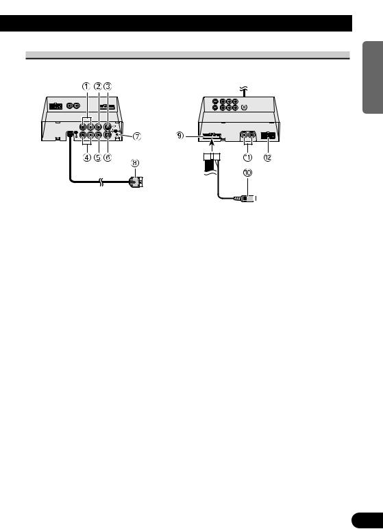
Names and Functions of Connection Terminals
■ Hide-away Unit
1VCR1 RCA audio input (white, red)
Receive stereo audio, as from a VCR, DVD or other AV equipment.
2VCR1 RCA video input (yellow)
Receives video, as from a VCR, DVD or other AV equipment.
3VCR1 S-VIDEO input (black)
Receives S-VIDEO output video when the display is teamed up with AV equipment supporting an S-VIDEO output terminal.
4VCR2 RCA audio input (white, red)
Receive stereo audio, as from a VCR, DVD or other AV equipment.
5VCR2 RCA video input (yellow)
Receives video, as from a VCR, DVD or other AV equipment.
6VCR2 S-VIDEO input (black)
Receives S-VIDEO output video when the display is teamed up with AV equipment supporting an S-VIDEO output terminal.
7RESET button
Resets the display microprocessor. Press with the tip of a ballpoint pen or similar object.
8Display RGB output (white)
Connects to the display unit.
9Power Supply
Receives the power cable supplied.
0RCA video output (yellow)
Connects to other AV equipment. Video selected with this display is directed to this terminal.
!RCA audio output (white, red)
Connect to other AV equipment. Audio selected with this display is directed to these terminals.
@RGB input (purple)
Use to connect a navigation unit or other Pioneer AV equipment.
NEDERLANDS ITALIANO AISÇFRAN DEUTSCH OLÑESPA ENGLISH
24
Connecting the System
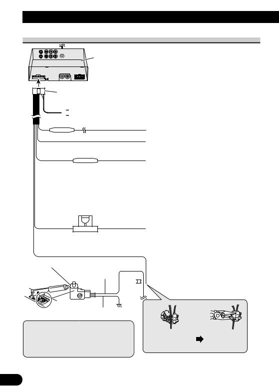
Connecting the Power Cable
Hide-away Unit
Power cable

 RCA video output (yellow) (Refer to page 28.)
Fuse resistor
Lightgreen/orange (Refer to page 29.)
Black (ground)
To vehicle (metal) body.
Red
To the electric terminal controlled by the ignition switch (12 V DC) ON/OFF.
Do not connect this lead to power source terminals to which power is continuously supplied. If the lead is connected to such terminals, the battery may be drained.
Yellow
To the terminal always supplied with power regardless of ignition switch position.
Light green
Used to detect the ON/OFF status of the parking brake. This lead must be connected to the power  supply side of the parking brake switch.
Note:
•The position of the parking brake switch depends on the vehicle model. For details, consult the vehicle Owner’s Manual or dealer.
Connecting method
Clamp the parking |
Clamp firmly |
|
brake switch power |
||
with needle-nosed |
||
supply side lead. |
||
pliers. |
||
|
25
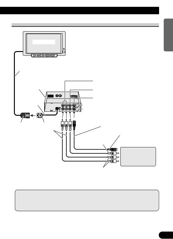
Connection Diagram (VCR input)
Display Unit
2.5 m
VCR1 RCA audio input (white, red)
Hide-away Unit
50 cm
Gray |
White |
Commercial RCA cable 
 (sold separately)
Note:
VCR1 RCA video input (yellow)
VCR1 S-VIDEO input (black)
VCR1 INPUT
VCR2 INPUT
S-VIDEO cable (sold separately)
To S-VIDEO output
To VIDEO output
Commercially available portable video component with RCA output
To AUDIO output
•When other AV equipment is connected to the VCR1 or VCR2 input, setting may be required. (Refer to page 17.)
•Even when an S-VIDEO signal is input to this unit, also input the RCA video signal (yellow) at the same time; otherwise, video will not be output from the video output jack of this unit.
NEDERLANDS ITALIANO AISÇFRAN DEUTSCH OLÑESPA ENGLISH
26
Connecting the System
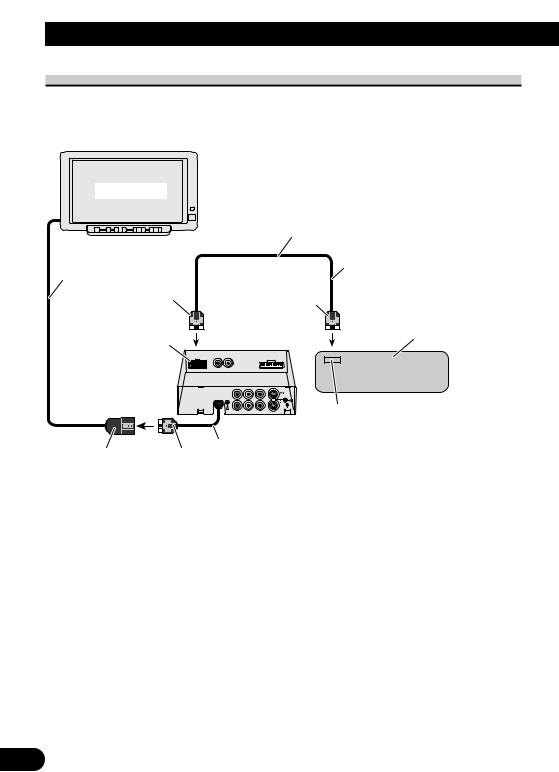
Connection Diagram (RGB input)
You can connect a separately sold Pioneer unit.
Display Unit
2.5 m
Purple
RGB input (purple)
Hide-away Unit
Gray |
White |
RGB cable (supplied)
3 m
Green
Navigation unit, AV master unit,
Hide-away TV tuner (sold separately)
RGB output (green)
Connect to the RGB output (green) of another AV equipment’s display.
50 cm (Output of the navigation’s guidance voice only is possible.)
27
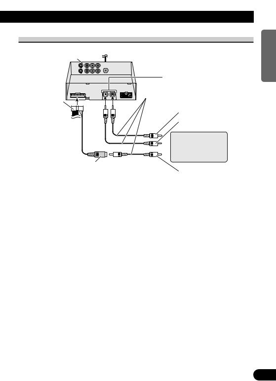
Connecting the RCA Audio and Video Output
Hide-away Unit
Power cable (Refer to page 25.)
15 cm 
RCA video output (yellow)
RCA audio output (white, red)
Commercial RCA cable (sold separately)
To audio input (R)
To audio input (L)
Second display, video deck, etc.
To video input
NEDERLANDS ITALIANO AISÇFRAN DEUTSCH OLÑESPA ENGLISH
28
Connecting the System
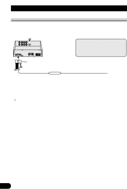
Connecting ”AUTOMATIC INPUT SWITCHING“ Lead
When using this product with a back-up camera, automatic switching to VCR1 video when the gear shift is moved to the REVERSE (R) position is possible.
Connect the back-up camera to the VTR1 input. (Refer to page 24.)
 Hide-away Unit
Power cable (Refer to page 25.)
Fuse resistor
Note:
•When you have completed lead wire connection, perform the appropriate settings for the connection method.
(Refer to page 19.)
Light
Of the connect the gear This the car
 CAUTION
This function is designed for use with a back-up camera only. Users may connect the VTR 1 input with “AUTOMATIC INPUT SWITCHING” only to such a back-up camera. Users must not connect any other devices to the VTR 1 input with “AUTOMATIC INPUT SWITCHING”.
29
 Loading...